WO2015156186A1 - モールドの製造方法およびロール状モールドの製造装置、ならびに微細凹凸構造を表面に有する物品の製造方法 - Google Patents
モールドの製造方法およびロール状モールドの製造装置、ならびに微細凹凸構造を表面に有する物品の製造方法 Download PDFInfo
- Publication number
- WO2015156186A1 WO2015156186A1 PCT/JP2015/060339 JP2015060339W WO2015156186A1 WO 2015156186 A1 WO2015156186 A1 WO 2015156186A1 JP 2015060339 W JP2015060339 W JP 2015060339W WO 2015156186 A1 WO2015156186 A1 WO 2015156186A1
- Authority
- WO
- WIPO (PCT)
- Prior art keywords
- mold
- release agent
- mold body
- outer peripheral
- peripheral surface
- Prior art date
- Legal status (The legal status is an assumption and is not a legal conclusion. Google has not performed a legal analysis and makes no representation as to the accuracy of the status listed.)
- Ceased
Links
Images




Classifications
-
- B—PERFORMING OPERATIONS; TRANSPORTING
- B29—WORKING OF PLASTICS; WORKING OF SUBSTANCES IN A PLASTIC STATE IN GENERAL
- B29C—SHAPING OR JOINING OF PLASTICS; SHAPING OF MATERIAL IN A PLASTIC STATE, NOT OTHERWISE PROVIDED FOR; AFTER-TREATMENT OF THE SHAPED PRODUCTS, e.g. REPAIRING
- B29C33/00—Moulds or cores; Details thereof or accessories therefor
- B29C33/56—Coatings, e.g. enameled or galvanised; Releasing, lubricating or separating agents
- B29C33/60—Releasing, lubricating or separating agents
- B29C33/62—Releasing, lubricating or separating agents based on polymers or oligomers
-
- B—PERFORMING OPERATIONS; TRANSPORTING
- B29—WORKING OF PLASTICS; WORKING OF SUBSTANCES IN A PLASTIC STATE IN GENERAL
- B29C—SHAPING OR JOINING OF PLASTICS; SHAPING OF MATERIAL IN A PLASTIC STATE, NOT OTHERWISE PROVIDED FOR; AFTER-TREATMENT OF THE SHAPED PRODUCTS, e.g. REPAIRING
- B29C33/00—Moulds or cores; Details thereof or accessories therefor
- B29C33/38—Moulds or cores; Details thereof or accessories therefor characterised by the material or the manufacturing process
- B29C33/3842—Manufacturing moulds, e.g. shaping the mould surface by machining
-
- B—PERFORMING OPERATIONS; TRANSPORTING
- B29—WORKING OF PLASTICS; WORKING OF SUBSTANCES IN A PLASTIC STATE IN GENERAL
- B29C—SHAPING OR JOINING OF PLASTICS; SHAPING OF MATERIAL IN A PLASTIC STATE, NOT OTHERWISE PROVIDED FOR; AFTER-TREATMENT OF THE SHAPED PRODUCTS, e.g. REPAIRING
- B29C33/00—Moulds or cores; Details thereof or accessories therefor
- B29C33/56—Coatings, e.g. enameled or galvanised; Releasing, lubricating or separating agents
- B29C33/58—Applying the releasing agents
-
- B—PERFORMING OPERATIONS; TRANSPORTING
- B29—WORKING OF PLASTICS; WORKING OF SUBSTANCES IN A PLASTIC STATE IN GENERAL
- B29C—SHAPING OR JOINING OF PLASTICS; SHAPING OF MATERIAL IN A PLASTIC STATE, NOT OTHERWISE PROVIDED FOR; AFTER-TREATMENT OF THE SHAPED PRODUCTS, e.g. REPAIRING
- B29C37/00—Component parts, details, accessories or auxiliary operations, not covered by group B29C33/00 or B29C35/00
- B29C37/006—Degassing moulding material or draining off gas during moulding
-
- B—PERFORMING OPERATIONS; TRANSPORTING
- B29—WORKING OF PLASTICS; WORKING OF SUBSTANCES IN A PLASTIC STATE IN GENERAL
- B29C—SHAPING OR JOINING OF PLASTICS; SHAPING OF MATERIAL IN A PLASTIC STATE, NOT OTHERWISE PROVIDED FOR; AFTER-TREATMENT OF THE SHAPED PRODUCTS, e.g. REPAIRING
- B29C37/00—Component parts, details, accessories or auxiliary operations, not covered by group B29C33/00 or B29C35/00
- B29C37/0067—Using separating agents during or after moulding; Applying separating agents on preforms or articles, e.g. to prevent sticking to each other
-
- B—PERFORMING OPERATIONS; TRANSPORTING
- B29—WORKING OF PLASTICS; WORKING OF SUBSTANCES IN A PLASTIC STATE IN GENERAL
- B29C—SHAPING OR JOINING OF PLASTICS; SHAPING OF MATERIAL IN A PLASTIC STATE, NOT OTHERWISE PROVIDED FOR; AFTER-TREATMENT OF THE SHAPED PRODUCTS, e.g. REPAIRING
- B29C59/00—Surface shaping of articles, e.g. embossing; Apparatus therefor
- B29C59/02—Surface shaping of articles, e.g. embossing; Apparatus therefor by mechanical means, e.g. pressing
- B29C59/022—Surface shaping of articles, e.g. embossing; Apparatus therefor by mechanical means, e.g. pressing characterised by the disposition or the configuration, e.g. dimensions, of the embossments or the shaping tools therefor
-
- B—PERFORMING OPERATIONS; TRANSPORTING
- B29—WORKING OF PLASTICS; WORKING OF SUBSTANCES IN A PLASTIC STATE IN GENERAL
- B29C—SHAPING OR JOINING OF PLASTICS; SHAPING OF MATERIAL IN A PLASTIC STATE, NOT OTHERWISE PROVIDED FOR; AFTER-TREATMENT OF THE SHAPED PRODUCTS, e.g. REPAIRING
- B29C59/00—Surface shaping of articles, e.g. embossing; Apparatus therefor
- B29C59/02—Surface shaping of articles, e.g. embossing; Apparatus therefor by mechanical means, e.g. pressing
- B29C59/04—Surface shaping of articles, e.g. embossing; Apparatus therefor by mechanical means, e.g. pressing using rollers or endless belts
-
- B—PERFORMING OPERATIONS; TRANSPORTING
- B29—WORKING OF PLASTICS; WORKING OF SUBSTANCES IN A PLASTIC STATE IN GENERAL
- B29C—SHAPING OR JOINING OF PLASTICS; SHAPING OF MATERIAL IN A PLASTIC STATE, NOT OTHERWISE PROVIDED FOR; AFTER-TREATMENT OF THE SHAPED PRODUCTS, e.g. REPAIRING
- B29C59/00—Surface shaping of articles, e.g. embossing; Apparatus therefor
- B29C59/02—Surface shaping of articles, e.g. embossing; Apparatus therefor by mechanical means, e.g. pressing
- B29C59/04—Surface shaping of articles, e.g. embossing; Apparatus therefor by mechanical means, e.g. pressing using rollers or endless belts
- B29C59/046—Surface shaping of articles, e.g. embossing; Apparatus therefor by mechanical means, e.g. pressing using rollers or endless belts for layered or coated substantially flat surfaces
-
- B—PERFORMING OPERATIONS; TRANSPORTING
- B29—WORKING OF PLASTICS; WORKING OF SUBSTANCES IN A PLASTIC STATE IN GENERAL
- B29C—SHAPING OR JOINING OF PLASTICS; SHAPING OF MATERIAL IN A PLASTIC STATE, NOT OTHERWISE PROVIDED FOR; AFTER-TREATMENT OF THE SHAPED PRODUCTS, e.g. REPAIRING
- B29C59/00—Surface shaping of articles, e.g. embossing; Apparatus therefor
- B29C59/02—Surface shaping of articles, e.g. embossing; Apparatus therefor by mechanical means, e.g. pressing
- B29C59/022—Surface shaping of articles, e.g. embossing; Apparatus therefor by mechanical means, e.g. pressing characterised by the disposition or the configuration, e.g. dimensions, of the embossments or the shaping tools therefor
- B29C2059/023—Microembossing
-
- B—PERFORMING OPERATIONS; TRANSPORTING
- B29—WORKING OF PLASTICS; WORKING OF SUBSTANCES IN A PLASTIC STATE IN GENERAL
- B29K—INDEXING SCHEME ASSOCIATED WITH SUBCLASSES B29B, B29C OR B29D, RELATING TO MOULDING MATERIALS OR TO MATERIALS FOR MOULDS, REINFORCEMENTS, FILLERS OR PREFORMED PARTS, e.g. INSERTS
- B29K2105/00—Condition, form or state of moulded material or of the material to be shaped
- B29K2105/0002—Condition, form or state of moulded material or of the material to be shaped monomers or prepolymers
-
- B—PERFORMING OPERATIONS; TRANSPORTING
- B29—WORKING OF PLASTICS; WORKING OF SUBSTANCES IN A PLASTIC STATE IN GENERAL
- B29K—INDEXING SCHEME ASSOCIATED WITH SUBCLASSES B29B, B29C OR B29D, RELATING TO MOULDING MATERIALS OR TO MATERIALS FOR MOULDS, REINFORCEMENTS, FILLERS OR PREFORMED PARTS, e.g. INSERTS
- B29K2905/00—Use of metals, their alloys or their compounds, as mould material
- B29K2905/02—Aluminium
Definitions
- the present invention relates to a method for producing a mold having a release agent layer formed on a mold body, an apparatus for producing a roll-shaped mold, and a method for producing an article having a fine concavo-convex structure on the surface.
- an article having a fine concavo-convex structure on the surface where the average interval between convex portions or concave portions is equal to or less than the wavelength of visible light exhibits an antireflection effect, a Lotus effect, and the like.
- a nano-order fine concavo-convex structure called a moth-eye structure is an effective anti-reflection measure because the refractive index continuously increases from the refractive index of air to the refractive index of the material of the article. It has been.
- a method of forming a fine concavo-convex structure on the surface of an article for example, a method of transferring a fine concavo-convex structure of a roll-shaped mold to the surface of an article using a roll-shaped mold in which an inverted structure of the fine concavo-convex structure is formed on the outer peripheral surface (Nanoimprint method) is known.
- the roll mold is manufactured, for example, by a method including a step of manufacturing a roll-shaped mold body having a fine uneven structure on the outer peripheral surface and a step of forming a release agent layer on the outer peripheral surface of the mold main body.
- the method (1) when removing the mold main body from the mold release agent treatment liquid, it is necessary to make the mold main body take-off speed extremely fine so that the liquid surface of the mold release agent treatment liquid does not wave. Therefore, it takes a long time to take out the mold body from the release agent treatment liquid. In particular, when the size of the mold main body is increased, it takes a very long time to remove the mold main body from the release agent treatment liquid, and the roll-shaped mold cannot be manufactured efficiently.
- the releasing agent solution is directly applied to the outer peripheral surface of the mold body, streaky coating unevenness is likely to occur.
- the release agent solution applied to the outer peripheral surface of the mold body is dried by the heater, streaky coating unevenness, dripping, etc. remain in the release agent layer as they are, and the release agent layer film Unevenness occurs in the thickness. If unevenness occurs in the film thickness of the release agent layer, when the fine uneven structure of the roll mold is transferred to the surface of the article, unevenness of the shape also occurs in the fine uneven structure on the surface of the article. Good goods cannot be obtained.
- the present invention provides a mold manufacturing method, a roll mold manufacturing apparatus, and a method for manufacturing an article having a fine concavo-convex structure on the surface, which can efficiently manufacture a mold in which unevenness of the film thickness of the release agent layer is suppressed. To do.
- the present invention includes, for example, the following mold production methods [1] to [11], the following roll mold production apparatuses [12] to [16], and the following [17] to [20].
- item which has the following fine uneven structure on the surface is mentioned.
- An agent solution is supplied to cause the mold release agent solution to adhere to the mold body, and gas is discharged from the gas discharge means disposed away from the mold body toward the mold release agent solution attached to the mold body. Then, the mold release agent solution is dried to form the mold release agent layer.
- the mold body is a roll body having a cylindrical outer shape, and the roll body while rotating the roll body with the central axis of the roll body as a rotation axis.
- the mold main body and the mold release agent discharging means are arranged so that the mold release agent discharging means is parallel to the central axis of the mold main body and is directed from the first end to the second end of the mold main body.
- a mold manufacturing method wherein gas is discharged from the gas discharge means toward the release agent solution attached to the outer peripheral surface of the mold main body while relatively moving the gas discharge means.
- the release agent solution is discharged from the release agent discharging means toward the lower half of the outer peripheral surface of the mold main body, and the release agent solution is adhered to the outer peripheral surface of the mold main body.
- a release agent solution is supplied toward the outer peripheral surface of the mold body from a plurality of the release agent discharge means arranged at equal intervals along the longitudinal direction of the mold body. [2] to [6 ] The manufacturing method of the mold in any one of. [8] Among the plurality of release agent discharge means arranged at equal intervals along the longitudinal direction of the mold main body, the mold in order from the release agent discharge means on the first end side of the mold main body. The mold release agent attached to the outer peripheral surface of the mold main body from the gas discharge means while supplying the release agent solution toward the outer peripheral surface of the main body and sequentially attaching the release agent solution to the outer peripheral surface of the mold main body. The method for producing a mold according to [7], wherein gas is discharged toward the agent solution.
- a method of manufacturing an article having a fine concavo-convex structure on a surface wherein a structure composed of a plurality of concavo-convex portions having an average period of 400 nm or less is formed on the surface of a roll-shaped mold body, and the central axis of the mold body is rotated While rotating the mold body as an axis, a release agent solution is supplied toward the outer peripheral surface of the mold body from a release agent discharging means disposed away from the mold body, and the outer peripheral surface of the mold body
- the mold release agent solution is attached to the mold body, and gas is discharged from the gas discharge means disposed away from the mold body toward the mold release agent solution attached to the outer peripheral surface of the mold body.
- the structure of the surface of the mold body on which the release agent layer is formed is transferred to the cured resin layer.
- the average interval of the convex portions adjacent to, characterized in that to produce an article having a surface a plurality of convex portions is 400nm or less, the production method of an article having a fine uneven structure on the surface.
- the roll-shaped mold main body includes the mold main body and the mold main body so that the release agent discharging means is parallel to the central axis of the mold main body and is directed from the first end to the second end of the mold main body. [18], which is obtained by supplying the release agent solution from the release agent discharge means to the outer peripheral surface of the mold body while relatively moving the release agent discharge means. A method for producing an article having a fine relief structure on its surface. [20] In the roll-shaped mold body, the gas discharge means disposed behind the release agent discharge means in the traveling direction of the release agent discharge means follows the release agent discharge means.
- the upper half of the outer peripheral surface of the mold body or “the lower half of the outer peripheral surface of the mold body” described in the present invention means that the roll-shaped mold main body is divided in half by a straight line in the diameter direction passing through the central axis.
- the side facing generally upward in the vertical direction is defined as “upper half of outer peripheral surface”
- the side facing generally downward is defined as “lower half of outer peripheral surface”.
- the mold manufacturing method of the present invention it is possible to efficiently manufacture a mold in which unevenness of the film thickness of the release agent layer is suppressed.
- the roll mold manufacturing apparatus of the present invention it is possible to efficiently manufacture a roll mold in which unevenness of the film thickness of the release agent layer is suppressed.
- the method for manufacturing an article having the fine uneven structure on the surface of the present invention an article with improved precision of the fine uneven shape can be efficiently produced.
- FIG. 2 It is sectional drawing which shows an example of the manufacturing process of the mold main body which has a fine concavo-convex structure on the surface.
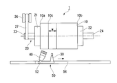
- FIG. 2 It is a top view which shows the manufacturing apparatus of the roll mold used for 1st Embodiment of this invention. It is the front view which looked at the manufacturing apparatus of FIG. 2 from the horizontal direction. It is the side view which looked at a part of manufacturing apparatus of Drawing 2 from the central axis direction of a mold main part. It is a top view which shows a mode that the mold release agent discharge nozzle and the gas discharge nozzle moved in the manufacturing apparatus of FIG. It is a top view which shows the manufacturing apparatus of the roll-shaped mold used for 2nd Embodiment of this invention. It is the front view which looked at the manufacturing apparatus of FIG.
- Uneven structure means a structure having a plurality of convex portions and / or a plurality of concave portions.
- the “fine concavo-convex structure” means a structure having a plurality of convex portions and / or a plurality of concave portions, and an average interval between the convex portions or the concave portions is nano-order.
- Nano-order means 1 nm or more and less than 1 ⁇ m.
- Gas includes any gas useful for drying the mold surface, such as air or inert gas.
- Pore means a concave portion having a fine concavo-convex structure formed in an oxide film on the surface of an aluminum substrate.
- Pore spacing means the distance between the centers of adjacent pores.
- the “outer peripheral surface of the mold body” means the outermost peripheral surface having a shape (concave / convex structure, mirror surface, etc.) transferred to the article. Therefore, when there is a small-diameter portion having a smaller diameter than the body portion having the outermost peripheral surface at both ends of the mold main body, the outer peripheral surface of the small-diameter portion is not included in the “outer peripheral surface of the mold main body”.
- the “end portion of the mold body” means an end portion of the body portion having the outermost peripheral surface in the length direction of the mold body.
- the “roll shape” means a columnar structure having a continuous outer peripheral surface such as a columnar shape or a hollow cylindrical shape.
- “Expansion width w of release agent solution” means that when the release agent solution is discharged from the release agent discharge nozzle toward the outer peripheral surface of the mold main body and adhered to the outer peripheral surface of the mold main body, It means a width in which the release agent solution spreads on the outer peripheral surface of the mold body during one rotation (see FIG. 2 and the like).
- “Initial holding time” refers to the discharge of the gas from the gas discharge nozzle after starting the discharge of the release agent solution from the release agent discharge nozzle toward the outer peripheral surface of the first end of the mold body and the vicinity thereof. It means the time until drying of the release agent solution adhering to the outer peripheral surface of the first end of the mold body starts. “Wetted time” means the time from when the release agent solution adheres to the outer peripheral surface of the mold main body until the start of drying of the release agent solution.
- a roll-shaped mold will be described as an example of the mold.
- the shape of the outer peripheral surface of the roll-shaped mold (uneven structure, mirror surface, etc.) is transferred to the surface of the article, and a shape corresponding to the shape of the outer peripheral surface of the roll-shaped mold is formed on the surface of the article. belongs to.
- Examples of the roll-shaped mold include a roll-shaped mold having a fine concavo-convex structure on the surface used in the nanoimprint method; an embossed roll used for forming an emboss; a roll-shaped stamper used for forming a bit of a recording medium.
- the roll-shaped mold obtained by the manufacturing method of the present embodiment has a roll-shaped mold body and a release agent layer formed on the outer peripheral surface of the mold body.
- the mold main body of the present embodiment is obtained by forming a concavo-convex structure on the outer peripheral surface of a roll-shaped base material, or by finishing the outer peripheral surface of a roll-shaped base material into a mirror surface.
- the mold body may be hollow or solid, that is, solid.
- the concavo-convex structure may be formed on at least a part of the outer peripheral surface of the mold main body, and may not be formed on the entire outer peripheral surface of the mold main body, or may be formed on the whole.
- the substrate examples include metals (including those having an oxide film formed on the surface), quartz, glass, resin, ceramics, and the like, and it is easy to form a fine uneven structure on the surface. Metal is preferred.
- Mold body manufacturing method Examples of the method for producing the mold body include the following method (I-1), method (I-2), etc., and the method (I- 1) is preferred.
- (I-1) A method of forming anodized alumina (a porous oxide film of aluminum) having a plurality of pores on the outer peripheral surface of a roll-shaped aluminum substrate.
- (I-2) A method of directly forming a fine concavo-convex structure on the outer peripheral surface of a roll-shaped substrate by an electron beam lithography method, a laser beam interference method or the like.
- a method having the following steps (a) to (f) is preferable.
- A) The process of forming an oxide film in the outer peripheral surface of an aluminum base material by anodizing a roll-shaped aluminum base material in electrolyte solution under a constant voltage.
- B) A step of removing a part or all of the oxide film and forming anodic oxidation pore generation points on the outer peripheral surface of the aluminum substrate.
- C) After the step (b), the step of anodizing the aluminum substrate again in the electrolytic solution to form an oxide film having pores at the pore generation points.
- D) A step of expanding the diameter of the pores after the step (c).
- E) A step of anodizing again in the electrolytic solution after the step (d).
- F) A step of obtaining a mold main body in which anodized alumina having a plurality of pores is formed on the outer peripheral surface of an aluminum substrate by repeatedly performing steps (d) and (e).
- the aluminum substrate is preferably polished by, for example, mechanical polishing, feather polishing, chemical polishing, electrolytic polishing (etching) or the like in order to smooth the surface state.
- the oil used when processing this aluminum base material into a predetermined shape may adhere, it is preferable that the aluminum base material is degreased in advance before anodizing.
- the purity of aluminum is preferably 99% or more, more preferably 99.5% or more, and further preferably 99.8% or more.
- the purity of aluminum is low, when anodized, an uneven structure having a size that scatters visible light due to segregation of impurities may be formed, or the regularity of pores obtained by anodization may be reduced. .
- electrolytic solution examples include aqueous solutions such as oxalic acid and sulfuric acid.
- aqueous solutions such as oxalic acid and sulfuric acid.
- One type of electrolytic solution may be used alone, or two or more types may be used in combination.
- the concentration of oxalic acid is preferably 0.7 M or less. When the concentration of oxalic acid exceeds 0.7M, the current value becomes too high, and the surface of the oxide film may become rough.
- an aqueous oxalic acid solution is used as the electrolytic solution, anodized alumina having highly regular pores with an average interval of 100 nm can be obtained when the formation voltage is 30 to 60V. Even if the formation voltage is higher or lower than the above range, the regularity tends to decrease.
- the temperature of the electrolytic solution is preferably 60 ° C. or lower, and more preferably 45 ° C. or lower. When the temperature of the electrolytic solution exceeds 60 ° C., a so-called “burn” phenomenon occurs, and the pores may be broken or the surface may melt and the regularity of the pores may be disturbed.
- the concentration of sulfuric acid is preferably 0.7M or less. If the concentration of sulfuric acid exceeds 0.7M, the current value may become too high to maintain a constant voltage.
- an aqueous sulfuric acid solution is used as the electrolytic solution, anodized alumina having highly regular pores with an average interval of 63 nm can be obtained when the formation voltage is 25 to 30 V. Even if the formation voltage is higher or lower than the above range, the regularity tends to decrease.
- the temperature of the electrolytic solution is preferably 30 ° C. or less, and more preferably 20 ° C. or less. When the temperature of the electrolytic solution exceeds 30 ° C., a so-called “burn” phenomenon occurs, and the pores may be broken or the surface may melt and the regularity of the pores may be disturbed.
- Examples of the method for removing the oxide film 16 include a method in which aluminum is not dissolved but the oxide film 16 is dissolved and removed in a solution that selectively dissolves. Examples of such a solution include a chromic acid / phosphoric acid mixed solution.
- the anodic oxidation in the step (c) may be performed under the same conditions as in the step (a). Deeper pores can be obtained as the anodic oxidation time is lengthened.
- the pore diameter expansion process is a process of expanding the diameter of the pores 14 obtained by anodic oxidation by immersing in a solution for dissolving the oxide film 16. Examples of such a solution include a phosphoric acid aqueous solution of about 5% by mass. The longer the time for the above-mentioned pore diameter expansion treatment, the larger the pore diameter.
- the total number of repetitions of the above step (d) and step (e) is preferably 3 times or more, and more preferably 5 times or more.
- the number of repetitions is 2 times or less, the diameter of the pores decreases discontinuously. Therefore, the reflectance of the fine concavo-convex structure (moth eye structure) formed by transferring the shape of the anodized alumina having such pores. The reduction effect is insufficient.
- Examples of the shape of the pore 14 include a substantially conical shape, a pyramid shape, a cylindrical shape, and a bell shape, and the cross-sectional area of the pore in the direction orthogonal to the depth direction is the outermost surface, such as a cone shape and a pyramid shape.
- a shape that continuously decreases in the depth direction from 1 to 2 is preferable.
- the average interval between the pores 14 is preferably not more than the wavelength of visible light, that is, not more than 400 nm.
- the average interval between the pores 14 is preferably 20 nm or more.
- the average interval between the pores 14 described in this embodiment is obtained by measuring 50 intervals between adjacent pores 14 (distance from the center of the pore 14 to the center of the adjacent pore 14) by electron microscope observation. These values are averaged.
- the depth of the pores 14 is preferably nano-order, more preferably 80 to 500 nm, further preferably 120 to 400 nm, and particularly preferably 150 to 300 nm.
- the depth of the pore 14 described in the present embodiment is the distance between the bottom of the pore 14 and the top of the convex portion existing between the pores 14 when observed at a magnification of 30000 by electron microscope observation. This is a value obtained by measuring the distance.
- the aspect ratio (pore depth / average interval between pores) of the pores 14 is preferably 0.8 to 5.0, more preferably 1.2 to 4.0, and 1.5 to 3.0. Is more preferable.
- the mold body 10 obtained in this manner is used in the method for producing a roll mold of the present invention, which will be described later, to obtain a roll mold in which a release agent layer is formed on the outer peripheral surface of the mold body.
- the release agent layer is a layer formed by attaching a release agent solution to the outer peripheral surface of the mold body and drying the release agent solution.
- the release agent contained in the release agent solution may exist as it is without being chemically changed, or the release agent contained in the release agent solution is chemically present. May exist in a state that has changed.
- release agent examples include silicone resins, fluororesins, fluorine compounds (specifically, see below), phosphate esters, and the like. From the viewpoint that release properties can be maintained for a long time, fluorine compounds or phosphate esters Is preferred.
- fluorine compounds examples include “Fluorolink” (registered trademark) manufactured by Solvay Specialty Polymers Japan, fluoroalkylsilane “KBM-7803” (registered trademark) manufactured by Shin-Etsu Chemical Co., Ltd., “ MRAF ”(registered trademark),“ OPTOOL HD1100 ”(registered trademark) manufactured by Harves,“ OPTOOL HD2100 series ”(registered trademark),“ OPTOOL DSX ”(registered trademark) manufactured by Daikin Industries, Ltd.,“ manufactured by Sumitomo 3M Limited ” Novec EGC-1720 "(registered trademark),” FS-2050 "series manufactured by Fluoro Technology, and the like.
- a (poly) oxyalkylene alkyl phosphoric acid compound is preferable from the viewpoint that the releasability can be maintained for a long time.
- Commercially available products include, for example, “JP-506H” manufactured by Johoku Chemical Industry Co., Ltd., “Mold With INT-1856” (registered trademark) manufactured by Accel Corporation, “TDP-10”, “TDP-8” manufactured by Nikko Chemicals Co., Ltd. ”,“ TDP-6 ”,“ TDP-2 ”,“ DDP-10 ”,“ DDP-8 ”,“ DDP-6 ”,“ DDP-4 ”,“ DDP-2 ”,“ TLP-4 ”, Examples include “TCP-5” and “DLP-10”. These release agents may be used alone or in combination of two or more.
- the mold manufacturing method of the present invention is a method for manufacturing a mold in which a mold release agent layer is formed on a mold body, and a mold release agent from a mold release agent discharging means disposed away from the mold body toward the mold body.
- the solution is supplied to attach the release agent solution to the mold body, and the gas is discharged from the gas discharge means arranged away from the mold body toward the release agent solution attached to the mold body to release the solution.
- An example described in the present embodiment is a method having the following adhesion step (S1) and the following drying step (S2) in manufacturing a roll-shaped mold.
- a mold release agent solution is supplied toward the outer peripheral surface of the mold body from a mold release agent discharging means disposed away from the mold body while rotating the mold body about the central axis of the mold body as a rotation axis. Attaching a release agent solution to the outer peripheral surface of the mold body; (S2) While rotating the mold body about the central axis of the mold body, gas is discharged from the gas discharge means arranged away from the mold body toward the release agent solution attached to the outer peripheral surface of the mold body. And drying the release agent solution to form a release agent layer.
- the adhesion step (S1) and the drying step (S2) may be performed simultaneously in parallel; the adhesion step (S1) may be performed first, and then the drying step (S2) may be performed; (S1) and the drying step (S2) may be performed alternately.
- the mold body may be rotated while holding the mold body so that the center axis of the mold body is not in the vertical direction.
- the adhesion step (S1) and the drying step (S2) are simultaneously performed in parallel, and when the adhesion step (S1) and the drying step (S2) are alternately performed, the adhesion step (S1) is separated. More preferably, the release agent solution is not discharged from the mold agent discharge means toward the dried region (release agent layer), that is, the release agent solution is not applied twice.
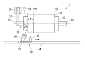
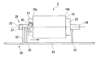
- FIG. 2 is a top view showing the roll mold manufacturing apparatus used in the first embodiment of the present invention
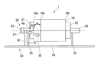
- FIG. 3 is a front view of the manufacturing apparatus of FIG. 2 seen from the horizontal direction
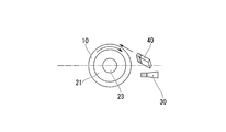
- FIG. FIG. 3 is a side view of a part of the manufacturing apparatus of FIG. 2 as viewed from the central axis direction of the mold body.
- the manufacturing apparatus 1 includes a rotation mechanism (rotating means) that rotates the mold body 10 about the central axis of the roll-shaped mold body 10 as a rotation axis; and is arranged away from the mold body 10 and toward the outer peripheral surface of the mold body 10.
- a release agent discharge nozzle 30 release agent discharge means for discharging the release agent solution and attaching the release agent solution to the outer peripheral surface of the mold body 10;
- a gas discharge nozzle 40 gas discharge means for discharging a gas toward the release agent solution adhering to the outer peripheral surface of the substrate 10 and drying the release agent solution to form a release agent layer;
- a moving mechanism (moving means) 50 for moving the release agent discharge nozzle 30 and the gas discharge nozzle 40 in parallel with the axis is provided. Further, in the present embodiment, by controlling the moving mechanism 50, a control unit that does not discharge the release agent solution from the release agent discharge nozzle 30 toward the dried area (release agent layer) ( An example of an apparatus provided with a not-illustrated) will be described.
- the rotation mechanism 20 includes a spindle-side holder 21 that holds the first end 10 a side of the mold body 10; a tail-side holder 22 that holds the second end 10 b side of the mold body 10; and the center of the mold body 10.
- a main shaft side shaft 23 connected to the main shaft side holder 21 coaxially with the shaft; a tail side shaft 24 connected to the tail side holder 22 coaxially with the central axis of the mold body 10;
- a shaft support 25 for supporting the tail side shaft 24; a rotation driving unit 26 including a motor (not shown); and a belt 27 for transmitting the rotation of the rotation driving unit 26 to the main shaft side shaft 23.
- the mold body 10 is held so that the center axis of the mold body 10 is in the horizontal direction.
- the mold body 10 is held so that the center axis of the mold body 10 is not in the vertical direction. It only has to be.
- the liquid contact time is the upper side of the mold body 10. Therefore, the film thickness of the release agent layer is likely to be uneven between the upper side and the lower side of the mold body 10. In addition, uneven coating due to liquid sag is likely to occur.
- the mold release agent layer is formed between the first end 10a side and the second end 10b side of the mold body 10. Unevenness in film thickness hardly occurs.
- the mold body 10 is preferably held so that the center axis of the mold body 10 is within ⁇ 10 degrees with respect to the horizontal direction, and is held so that the center axis of the mold body 10 is in the horizontal direction. Is particularly preferred.
- a shaft member such as a mandrel inserted through the inside of the hollow roll-shaped mold body may be used.
- the rotation mechanism 20 should just rotate the mold release agent discharge nozzle 30, the gas discharge nozzle 40, and the mold main body 10, for example, the mold release agent discharge nozzle 30 around the mold main body 10.
- a mechanism for rotating the gas discharge nozzle 40 may be used.
- Release agent discharge nozzle The shape of the discharge port of the release agent discharge nozzle 30 is circular.
- the release agent discharge nozzle 30 is disposed so that the release agent solution discharged from the release agent discharge nozzle 30 adheres to the lower half of the outer peripheral surface of the mold body 10. Further, the release agent discharge nozzle 30 is arranged so that the discharge direction of the release agent solution from the release agent discharge nozzle 30 is in a direction along the rotation direction of the mold body 10.
- the shape of the discharge port of the release agent discharge nozzle 30 is circular, but in the present invention, the shape of the discharge port may be any shape that can discharge the release agent solution. Alternatively, an elliptical shape, a rectangular shape, or a shape in which a plurality of holes are arranged in a straight line may be used. Among these shapes, the shape of the discharge port is preferably a circular shape from the viewpoint of easy control of the discharge pressure of the release agent and the discharge pattern.
- the number of release agent discharge nozzles 30 is one. However, in the present invention, the number may be two or more.
- the release agent discharge nozzle 30 is disposed so that the release agent solution adheres to the lower half of the outer peripheral surface of the mold body 10. You may arrange
- the release agent discharge nozzle 30 is arranged so that the release direction of the release agent solution is in a direction (forward direction) along the rotation direction of the mold body 10, but in the present invention, You may arrange
- the release agent solution discharge nozzle 30 has a discharge direction of the release agent solution in a direction along the rotation direction of the mold body 10 because the release agent solution is less likely to scatter and the spread width w of the release agent solution is easily stabilized. It is preferable that they are arranged as described above.
- Gas discharge nozzle The shape of the discharge port of the gas discharge nozzle 40 is rectangular.
- the gas discharge nozzle 40 is disposed behind the release agent discharge nozzle 30 with respect to the traveling direction of the release agent discharge nozzle 30. Further, the gas discharge nozzle 40 is at a position higher in the vertical direction than the release agent discharge nozzle 30, and the gas having a certain width discharged from the gas discharge nozzle 40 is positioned in the upper half of the outer peripheral surface of the mold body 10. It arrange
- the gas discharge nozzle 40 is arranged so that the gas discharge direction from the gas discharge nozzle 40 is opposite to the rotation direction of the mold body 10.
- the shape of the discharge port of the gas discharge nozzle 40 is rectangular.
- any shape that can discharge gas may be used.
- a circular shape, an elliptical shape, and a plurality of holes are provided.
- the shape etc. which were located in a line may be sufficient.
- the shape of the discharge port is preferably an elongated rectangular shape (slit shape) or a shape in which a plurality of holes are arranged in a straight line from the viewpoint of easily discharging a gas having a certain width.
- the number of gas discharge nozzles 40 is one, but in the present invention, two or more may be used.
- the gas discharge nozzle 40 is positioned higher in the vertical direction than the release agent discharge nozzle 30, and the gas sprays on the release agent solution located in the upper half of the outer peripheral surface of the mold body 10.
- the gas discharge nozzle 40 is in a position lower than the release agent discharge nozzle 30 in the vertical direction, and the gas is positioned in the lower half of the outer peripheral surface of the mold body 10. You may arrange
- the gas discharge nozzle 40 is positioned lower than the release agent discharge nozzle 30 and the gas is sprayed onto the release agent solution located in the lower half of the outer peripheral surface of the mold body 10.
- the release agent solution discharged from the release agent discharge nozzle 30 flows down and hangs down in the lower half of the outer peripheral surface of the mold body 10 where the lower half has been dried (release agent layer).
- the gas discharge nozzle 40 is positioned so as to be higher in the vertical direction than the mold release agent discharge nozzle 30, and the gas is sprayed onto the mold release agent solution located in the upper half of the outer peripheral surface of the mold body 10. It is preferable.
- the gas discharge nozzle 40 is disposed so that the gas discharge direction is opposite to the rotation direction of the mold body 10 (reverse direction). You may arrange
- the gas discharge nozzle 40 is disposed so that the gas discharge direction is opposite to the rotation direction of the mold body 10 from the viewpoint that the mold release agent solution on the outer peripheral surface of the mold body 10 can be dried more efficiently. It is preferred that
- the gas discharge nozzle 40 is preferably arranged so that the gas discharge direction is inclined with respect to the central axis of the mold body 10.
- the angle ⁇ on the first end portion 10a side formed by the gas discharge direction and the central axis of the mold body 10 when viewed from above in the vertical direction shown in FIG. The degree is preferably less than 10 degrees, and more preferably 10 to 80 degrees.
- the angle ⁇ is within the above range, the gas discharged from the gas discharge nozzle 40 makes it difficult for the release agent solution to flow into the dried area (release agent layer), and the film thickness of the release agent layer. Unevenness is unlikely to occur.
- the moving mechanism 50 includes a nozzle fixture 52 that fixes the release agent discharge nozzle 30 and the gas discharge nozzle 40; and a linear guide 54 that moves the nozzle fixture 52 in parallel with the center axis of the mold body 10. Since the gas discharge nozzle 40 is fixed to the nozzle fixture 52 together with the release agent discharge nozzle 30, the gas discharge nozzle 40 can move so as to follow the release agent discharge nozzle 30.
- the moving mechanism 50 moves the release agent discharge nozzle 30 and the gas discharge nozzle 40.
- the mold body 10, the release agent discharge nozzle 30 and the gas discharge nozzle 40 are moved. Are more preferable if they are relatively moved.
- the mold body 10 may be moved so as to cross the front of the fixed release agent discharge nozzle 30 and the gas discharge nozzle 40.
- Control means controls the moving mechanism 50 to operate so as not to discharge the release agent solution from the release agent discharge nozzle 30 toward the dried area (release agent layer). Is possible. That is, while the release agent solution is being discharged from the release agent discharge nozzle 30, the control means is configured such that the release agent discharge nozzle 30 moves from the first end 10 a side of the mold body 10 to the second end portion of the mold body 10. The release agent discharge nozzle 30 and the gas discharge nozzle 40 that follows the release agent discharge nozzle 30 are moved toward the 10b side. However, the release agent discharge nozzle 30 and the gas discharge nozzle 40 that follows the release agent discharge nozzle 30 are moved away from the second end portion 10b side of the mold body 10 toward the first end portion 10a side. The mold material discharge nozzle 30 and the gas discharge nozzle 40 preceding the mold material discharge nozzle 30 can be operated so as not to move.
- control means controls the supply of the release agent solution to the release agent discharge nozzle 30, the supply of gas to the gas discharge nozzle 40, and the moving mechanism 50, so that the first end portion 10 a of the mold body 10 is controlled.
- the release agent solution is discharged from the release agent discharge nozzle 30 toward the outer peripheral surface of the mold body 10, and the first end 10 a and the first end of the mold body 10 are discharged.
- a release agent solution is adhered to the outer peripheral surface of the region having a width w extending from the portion 10a.
- control means moves the release agent discharge nozzle 30 after a predetermined time has elapsed from the start of discharge of the release agent solution, and moves the release agent discharge nozzle 30 from the gas discharge nozzle 40 that follows the release agent discharge nozzle 30. Gas is discharged toward the release agent solution adhering to the outer peripheral surface of the one end portion 10a.
- control means (not shown) can provide an initial holding time in the roll mold manufacturing method described later.
- the control means includes a processing unit (not shown), an interface unit (not shown), and a storage unit (not shown).
- the interface unit includes a rotation unit 20, a unit (not shown) for supplying a release agent solution to the release agent discharge nozzle 30, a unit (not shown) for supplying a gas to the gas discharge nozzle 40, a moving unit 50, and a processing unit.
- the processing unit controls each means based on settings (initial holding time, moving speed, rotation speed, discharge flow rate of release agent solution, gas source pressure, etc.) stored in the storage unit.
- the above processing unit may be realized by dedicated hardware, and the above processing unit is configured by a memory and a central processing unit (CPU) for realizing the function of the processing unit.
- the function may be realized by loading a program into a memory and executing the program.
- an input device, a display device, and the like are connected to the control means as peripheral devices.
- the input device refers to an input device such as a display touch panel, a switch panel, or a keyboard
- the display device refers to a CRT, a liquid crystal display device, or the like.
- the mold manufacturing method includes the following adhesion step (S1) and the following drying step (S2).
- S1 A mold release that is spaced apart from the mold body 10 while rotating the mold body 10 about the center axis as a rotation axis while holding the mold body 10 so that the center axis of the mold body 10 is horizontal.
- S2 Gas discharge disposed away from the mold body 10 while rotating the mold body 10 with the center axis as a rotation axis while holding the mold body 10 so that the center axis of the mold body 10 is horizontal.
- the adhesion step (S1) and the drying step (S2) are performed in parallel.
- the release agent solution is applied from the release agent discharge nozzle 30 toward the region where the drying is finished (release agent layer). It is preferable not to discharge, that is, not to apply the release agent solution twice.
- Adhesion step (S1), drying step (S2): (I) When manufacturing the roll-shaped mold used for the nanoimprint method, it is preferable that each step is performed in a clean environment. By performing each step in a clean environment, when gas is blown from the gas discharge nozzle 40 to the mold body 10, dust, dust, etc. are blown to the outer peripheral surface of the mold body 10, and fine scratches or the like are attached. Moreover, it can suppress that a foreign material adheres to the outer peripheral surface of the mold main body 10.
- “under a clean environment” means a class of 1000 or less in the FED standard, and a class of 1000 or less is preferable because adhesion of foreign matters can be more effectively suppressed.
- the mold body 10 is held by the spindle side holder 21 and the tail side holder 22 so that the central axis of the mold body 10 is in the horizontal direction.
- the mold body 10 is held such that the center axis of the mold body 10 is in the horizontal direction.
- the mold body 10 is held so that the center axis of the mold body 10 is not in the vertical direction. That's fine.
- the release agent layer is formed between the first end 10a side and the second end 10b side of the mold body 10. The film thickness is less likely to be uneven.
- the mold body 10 it is preferable to hold the mold body 10 so that the center axis of the mold body 10 is within ⁇ 10 degrees with respect to the horizontal direction, and it is particularly preferable to hold the mold body 10 so that the center axis of the mold body 10 is in the horizontal direction.
- the mold body 10 is rotated by the rotation mechanism 20 with the central axis of the mold body 10 as the rotation axis. The rotation of the mold body 10 is continued until the formation of the release agent layer is completed.
- the mold release agent discharge nozzle 30 disposed away from the mold body 10 without moving the release agent discharge nozzle 30 is moved from the mold release agent discharge nozzle 30 to the outer peripheral surface of the mold body 10.
- the release agent solution is discharged and supplied toward the first end 10a of the mold body 10 and the release agent solution is adhered to the outer peripheral surface of the region having the spreading width w from the first end 10a.
- the release agent discharge nozzle 30 is moved to the second end portion 10b side of the mold body 10 to follow the release agent discharge nozzle 30. Gas is discharged toward the release agent solution adhering to the outer peripheral surface of the first end portion 10a of the mold main body 10. Thereby, an initial holding time can be provided.
- the mold release agent discharge nozzle 30 is formed such that the spread width w of the mold release agent solution is formed at the position shown in FIG. 2, that is, the first end portion 10a of the mold body 10 and the outer peripheral surface in the vicinity thereof.
- the release agent solution is sufficiently released before the release agent solution sufficiently adheres to the outer peripheral surface of the first end portion 10a of the mold body 10.
- the agent discharge nozzle 30 moves. Therefore, when the release agent discharge nozzle 30 starts to discharge the release agent solution at the position shown in FIG. 2, an initial holding time is provided to release the release agent solution on the outer peripheral surface of the first end 10 a of the mold body 10.
- the mold solution is sufficiently adhered to reduce the difference in film thickness of the release agent layer between the first end 10a of the mold body 10 and the other region.
- the initial holding time of the release agent discharge nozzle 30 preferably satisfies the following relationship. That is, when the spreading width w of the release agent solution is 60 mm, the initial holding time is preferably 40 seconds or more and 600 seconds or less. w ⁇ 2/3 ⁇ T ⁇ w ⁇ 10 In the above formula, T is the initial holding time [second], and w is the spreading width w [mm] of the release agent solution. If the initial holding time T is w ⁇ 2/3 or more, the release agent solution is sufficiently attached to the first end portion 10a of the mold body 10, so that the first end portion 10a of the mold body 10 and other parts The difference in film thickness of the release agent layer can be made sufficiently small between the locations. If the initial holding time T is equal to or less than w ⁇ 10, the roll mold can be efficiently manufactured, and the film thickness of the first end portion 10a of the mold body 10 and the release agent layer in the vicinity thereof is too thick. Absent.
- the release agent discharge nozzle 30 is located behind the first end portion 10a of the mold body 10 with respect to the traveling direction of the release agent discharge nozzle 30, that is, toward the main shaft side shaft 23 and the main shaft side holder 21.
- the release agent solution and the movement of the release agent discharge nozzle 30 are started simultaneously from the position where the release agent solution is discharged, it is not necessary to provide an initial holding time.
- the main shaft side shaft 23 and the main shaft side holder 21 are contaminated by the release agent, or the release agent solution discharged toward the main shaft side shaft 23 and the main shaft side holder 21 is wasted. There is a problem such as.
- the release agent solution When the release agent solution is discharged from the release agent discharge nozzle 30, the release agent solution is discharged from the release agent discharge nozzle 30 whose discharge port has a circular shape. Further, when the release agent solution is discharged from the release agent discharge nozzle 30, the release agent solution is discharged toward the lower half of the outer peripheral surface of the mold body 10, and the release agent is applied to the outer peripheral surface of the mold body 10. Let the solution adhere. Further, when the release agent solution is discharged from the release agent discharge nozzle 30, the release agent solution is discharged from the release agent discharge nozzle 30 so that the discharge direction of the release agent solution is along the rotation direction of the mold body 10. The mold solution is discharged.
- the release agent solution is discharged from the release agent discharge nozzle 30 whose discharge port has a circular shape.
- the discharge port has an elliptical or rectangular shape.
- the release agent solution may be discharged from a release agent discharge nozzle having a shape in which a plurality of holes are arranged in a straight line.
- the release agent solution is discharged from one release agent discharge nozzle 30, but in the present invention, the release agent solution is discharged from two or more release agent discharge nozzles 30. May be.
- the release agent solution is discharged from the release agent discharge nozzle 30 toward the lower half of the outer peripheral surface of the mold main body 10.
- the upper half of the outer peripheral surface of the mold main body 10 is discharged.
- the release agent solution may be discharged from the release agent discharge nozzle 30.
- the release agent solution is discharged from the release agent discharge nozzle 30 so that the discharge direction of the release agent solution from the release agent discharge nozzle 30 is the direction along the rotation direction of the mold body 10 (forward direction).
- the release agent is discharged so that the discharge direction of the release agent solution from the release agent discharge nozzle 30 is opposite to the rotation direction of the mold body 10 (reverse direction).
- the release agent solution may be discharged from the discharge nozzle 30.
- the release agent solution is discharged from the release agent discharge nozzle 30 so that the discharge direction of the release agent solution from the release agent discharge nozzle 30 is the direction along the rotation direction of the mold body 10. It is preferable.
- the discharge flow rate of the release agent solution discharged from the release agent discharge nozzle 30 is not particularly limited, but is preferably, for example, 400 to 800 mL / min / line. If the discharge flow rate of the release agent solution is 400 mL / min / line or more, the release agent solution reaches the outer peripheral surface of the mold body 10 sufficiently, and the release agent solution adheres sufficiently to the outer peripheral surface of the mold body 10. . On the other hand, when the discharge flow rate of the release agent solution exceeds 800 mL / min / book, the release agent solution adhering to the outer peripheral surface of the mold body 10 scatters and adheres to the region (release agent layer) that has been dried, There is a risk of unevenness in the film thickness of the release agent layer.
- the number of release agent discharge nozzles 30 used in the manufacturing apparatus of the present invention is not particularly limited, and can be determined as appropriate according to the size of the mold body 10 and the like.
- the spreading width w of the release agent solution is preferably shorter than the length in the direction of the central axis of the mold body 10 from the viewpoint that the release agent solution can be efficiently attached to the outer peripheral surface of the mold body 10. More preferably, it is less than half of the length in the direction of the central axis, and more preferably the same as the width of the gas discharged from the gas discharge nozzle 40.
- the temperature of the release agent solution sprayed on the outer peripheral surface of the mold body 10 is preferably 10 to 50 ° C, more preferably 15 to 30 ° C. If the temperature of the release agent solution is less than 10 ° C., condensation may occur on the outer peripheral surface of the mold body 10, and application unevenness may occur. If the temperature exceeds 50 ° C., the surface of the mold body 10 is dried too quickly, and the film thickness of the release agent layer may be uneven. In addition, when the material of the mold main body 10 is aluminum, if the temperature is 50 ° C. or lower, corrosion of aluminum can be suppressed.
- the concentration of the release agent in the release agent solution is preferably 0.05 to 0.1% by mass with respect to the total mass of the release agent solution. If the release agent concentration is 0.05% by mass or more, a release agent layer having a sufficient film thickness can be formed. Moreover, if a mold release agent density
- the spread width w of the release agent solution discharged from the release agent discharge nozzle 30 and attached to the outer peripheral surface of the mold body 10 is greater than the length of the mold body 10 in the direction of the central axis. Also short. Therefore, in order to provide an initial holding time, after starting the movement of the release agent discharge nozzle 30 that has not been moved, the release agent discharge nozzle 30 is parallel to the center axis of the mold body 10 and While moving the release agent discharge nozzle 30 from the first end portion 10a toward the second end portion 10b, the spreading width w of the release agent solution adhering to the outer peripheral surface of the mold body 10 becomes a predetermined width. In addition, the release agent solution is discharged from the release agent discharge nozzle 30 toward the outer peripheral surface of the mold body 10. As a result, the release agent solution is adhered to the entire outer peripheral surface of the mold body.
- the moving speed of the release agent discharge nozzle 30 is preferably 1 to 5 mm / second relative to the mold body 10. If the moving speed is 1 mm / second or more, a roll-shaped mold can be produced efficiently. Moreover, if the moving speed is 5 mm / second or less, a release agent layer having a sufficient film thickness can be formed.
- the liquid contact time is such that the release agent solution adheres during the initial holding time from the viewpoint of reducing the difference in film thickness of the release agent layer between the first end portion 10a side and the second end portion 10b side of the mold body 10. It is preferable that it is substantially the same over the entire mold body 10 including the region. However, the circle on the outer peripheral surface of the mold body 10 where the end of the spreading width w of the release agent solution shown in FIG. 2 (that is, the region where the release agent solution adheres during the initial holding time) on the second end portion 10b side is located. In the periphery 10c, as shown in FIG. 5, the release agent solution is moved until the end of the release agent solution spreading width w moves toward the first end 10a side as the release agent discharge nozzle 30 moves. Will adhere.
- the liquid contact time on the circumference 10c of the outer peripheral surface of the mold body 10 is the sum of the initial retention time and the liquid contact time other than the region where the release agent solution adheres during the initial retention time. Therefore, the release agent discharge nozzle 30 is released at the position shown in FIG. 2, that is, at the position where the spread width w of the release agent solution is formed on the first end portion 10a of the mold body 10 and the outer peripheral surface in the vicinity thereof.
- the liquid contact time is substantially the same over the entire mold body 10 except the region where the release agent solution adheres during the initial holding time.
- the initial holding time from the point of reducing the difference in film thickness of the release agent layer between the region where the release agent solution adheres and the other region in the initial holding time on the outer peripheral surface of the mold body 10 Is preferably shorter than the contact time other than the region where the release agent solution adheres in the initial holding time.
- the contact time other than the region where the release agent solution adheres during the initial holding time is preferably 1 to 30 minutes, more preferably 1 to 10 minutes. If said liquid contact time is 1 minute or more, the mold release agent layer of sufficient film thickness can be formed. Moreover, if said liquid contact time is 30 minutes or less, the film thickness of a mold release agent layer will not be too thick, and the coating nonuniformity will be suppressed.
- the release agent discharge nozzle 30 moves more than the release agent discharge nozzle 30 in the direction of travel.
- the release agent solution adhered to the outer peripheral surface of the mold body 10 from the gas discharge nozzle 40 is moved while the gas discharge nozzle 40 is moved so that the gas discharge nozzle 40 arranged at the rear follows the release agent discharge nozzle 30.
- the gas is discharged toward it.
- the release agent solution is applied from the release agent discharge nozzle 30 toward the outer peripheral surface of the mold body 10 so that the spreading width w of the release agent solution adhering to the outer peripheral surface of the mold body 10 becomes a predetermined width.
- a gas having a predetermined width is discharged from the gas discharge nozzle 40 toward the release agent solution adhering to the outer peripheral surface of the mold body 10. Accordingly, the release agent solution can be dried following the attachment of the release agent solution and at the same speed as the attachment of the release agent solution.
- gas When gas is discharged from the gas discharge nozzle 40, gas is discharged from the gas discharge nozzle 40 whose discharge port has a rectangular shape. Further, when the gas is discharged from the gas discharge nozzle 40, the gas discharge nozzle 40 that is higher in the vertical direction than the release agent discharge nozzle 30 adheres to the outer peripheral surface of the mold body 10, and Gas is discharged toward the release agent solution located in the upper half of the outer peripheral surface. Further, when gas is discharged from the gas discharge nozzle 40, it adheres to the outer peripheral surface of the mold body 10 so that the gas discharge direction from the gas discharge nozzle 40 is opposite to the rotation direction of the mold body 10. A gas is discharged toward the released release agent solution.
- the gas is discharged from the gas discharge nozzle 40 whose discharge port has a rectangular shape.
- the discharge port has a circular shape, a rectangular shape, and a plurality of holes.
- Gas may be discharged from a gas discharge nozzle having a shape aligned in a straight line.
- gas is discharged from one gas discharge nozzle 40, but in the present invention, gas may be discharged from two or more gas discharge nozzles 40.
- gas is discharged from the gas discharge nozzle 40 located higher in the vertical direction than the release agent discharge nozzle 30 toward the release agent solution located in the upper half of the outer peripheral surface of the mold body 10.
- gas is discharged from the gas discharge nozzle 40 located at a position lower than the release agent discharge nozzle 30 toward the release agent solution located in the lower half of the outer peripheral surface of the mold body 10. Also good.
- gas is discharged from the gas discharge nozzle 40 located higher in the vertical direction than the release agent discharge nozzle 30 toward the release agent solution located in the upper half of the outer peripheral surface of the mold body 10. It is preferable.
- the gas is discharged from the gas discharge nozzle 40 so that the gas discharge direction from the gas discharge nozzle 40 is opposite to the rotation direction of the mold body 10 (reverse direction).
- the gas may be discharged from the gas discharge nozzle 40 so that the gas discharge direction from the gas discharge nozzle 40 is a direction (forward direction) along the rotation direction of the mold body 10.
- the gas is discharged from the gas discharge nozzle 40 so that the gas discharge direction from the gas discharge nozzle 40 is inclined with respect to the central axis of the mold body 10.
- the angle ⁇ on the first end portion 10a side formed by the gas discharge direction and the central axis of the mold body 10 when viewed from above in the vertical direction shown in FIG. The degree is preferably less than 10 degrees, and more preferably 10 to 80 degrees.
- the pressure of the gas discharged from the gas discharge nozzle 40 is preferably 0.3 MPa to 0.6 MPa, more preferably 0.4 MPa to 0.6 MPa.
- the gas pressure is 0.3 MPa or more, the release agent solution attached to the outer peripheral surface of the mold body 10 can be dried without causing unevenness in the film thickness of the release agent layer. Further, since it is not necessary to bring the gas discharge nozzle 40 and the mold main body 10 closer than necessary, contact between the gas discharge nozzle 40 and the mold main body 10 can be prevented.
- the gas pressure exceeds 0.6 MPa, the release agent solution adhering to the outer peripheral surface of the mold body 10 scatters and adheres to the dried region (release agent layer), and the release agent layer film There is a risk of unevenness in thickness.
- the width of the gas discharged from the gas discharge nozzle 40 is preferably shorter than the length in the direction of the central axis of the mold body 10 from the viewpoint that the gas can be efficiently sprayed on the outer peripheral surface of the mold body 10. It is more preferably less than or equal to half the length of the main body 10 in the direction of the central axis, and more preferably about the same as the spreading width w of the release agent solution.
- the temperature of the gas sprayed on the outer peripheral surface of the mold body 10 is preferably 10 to 50 ° C., more preferably 15 to 30 ° C. If the temperature of the gas is less than 10 ° C., condensation may occur on the outer peripheral surface of the mold body 10, and coating unevenness may occur. Moreover, when the temperature of said gas exceeds 50 degreeC, there exists a possibility that the drying of the surface of the mold main body 10 may become too early, and the film thickness of a mold release agent layer may generate
- the release agent discharge nozzle 30 it is preferable not to discharge the release agent solution from the release agent discharge nozzle 30 toward the region (release agent layer) where the drying is finished. That is, while the release agent solution is discharged from the release agent discharge nozzle 30, the release agent discharge nozzle 30 is parallel to the central axis of the mold body 10 from the first end 10 a side to the second end.
- the release agent discharge nozzle 30 and the gas discharge nozzle 40 that follows the mold release nozzle 30 are moved so as to go to the portion 10b side, but from the second end portion 10b side of the mold body 10 to the first end portion 10a side, The release agent discharge nozzle 30 and the gas discharge nozzle 40 preceding this are not moved.
- the film thickness of the release agent solution can be made uniform, and further, streaky coating unevenness, dripping, and the like can be removed. Further, in a state where the mold body 10 is held so that the center axis of the mold body 10 is not in the vertical direction, the mold body 10 is rotated about the center axis as a rotation axis, so that the center axis of the mold body 10 is set to the vertical direction. Compared with the case where it does, the film thickness of a mold release agent layer does not produce a nonuniformity with the 1st end part 10a side of the mold main body 10, and the 2nd end part 10b side.
- the first embodiment it is possible to efficiently manufacture a roll-shaped mold in which unevenness of the film thickness of the release agent layer is suppressed even when the mold body is enlarged.
- it is suitable for producing a roll-shaped mold having a nano-order fine concavo-convex structure on the outer peripheral surface, in which the influence of unevenness of the film thickness of the release agent layer tends to appear remarkably.
- the release agent discharge nozzle 30 is directed so that the release agent discharge nozzle 30 is parallel to the central axis of the mold main body 10 from the first end portion 10a toward the second end portion 10b. While moving the nozzle 30, the release agent solution is discharged from the release agent discharge nozzle 30 toward the outer peripheral surface of the mold body 10, and at the same time, the release agent discharge nozzle 30 with respect to the traveling direction of the release agent discharge nozzle 30.
- the release agent attached to the outer peripheral surface of the mold body 10 from the gas discharge nozzle 40 while moving the gas discharge nozzle 40 so that the gas discharge nozzle 40 arranged behind the release agent discharge nozzle 30 follows. Gas is discharged toward the solution.
- the unevenness of the liquid contact time is reduced over the entire outer peripheral surface of the mold body 10, and the unevenness of the film thickness of the release agent layer is further suppressed.
- the release agent solution is discharged from the release agent discharge nozzle 30 toward the outer peripheral surface of the mold body 10 so that the spreading width w of the release agent solution adhering to the outer peripheral surface of the mold body 10 becomes a predetermined width.
- the release agent solution is dried to adhere to the release agent solution. Subsequently, it is performed at the same speed as that of the release agent solution. Therefore, the unevenness of the liquid contact time is further reduced over the entire outer peripheral surface of the mold body 10, and the unevenness of the film thickness of the release agent layer is further suppressed.
- the mold release agent solution is discharged toward the first end portion 10a and the outer peripheral surface in the vicinity thereof, and the mold release agent solution is discharged after a predetermined time has elapsed from the start of the release of the mold release agent solution.
- the nozzle 30 is moved, and gas is discharged from the gas discharge nozzle 40 following the release agent discharge nozzle 30 toward the release agent solution attached to the outer peripheral surface of the first end portion 10a.
- the release agent solution can be sufficiently adhered to the outer peripheral surface of the first end portion 10a of the mold main body 10, and as a result, the separation between the first end portion 10a of the mold main body 10 and the other region.
- the difference in film thickness of the mold agent layer can be reduced.
- the release agent solution is discharged and supplied from the release agent discharge nozzle 30 toward the lower half of the outer peripheral surface of the mold main body 10 to be applied to the outer peripheral surface of the mold main body 10.
- the upper part of the outer peripheral surface of the mold body 10 is attached to the outer peripheral surface of the mold body 10 from the gas discharge nozzle 40 which is higher than the release agent discharge nozzle 30 in the vertical direction.
- a gas having a certain width is discharged toward the release agent solution located in the area.
- the release agent solution discharged from the release agent discharge nozzle 30 flows down and hangs down on the region (release agent layer) where the lower half of the outer peripheral surface of the mold body 10 has been dried, and the release agent layer There is no risk of unevenness in the film thickness.
- the gas discharge nozzle 40 to the mold body 10 are arranged so that the gas discharge direction from the gas discharge nozzle 40 is opposite to the rotation direction of the mold body 10. Gas is discharged toward the release agent solution adhering to the outer peripheral surface. Therefore, the mold release agent solution on the outer peripheral surface of the mold body 10 can be dried more efficiently.
- FIG. 6 is a top view showing a roll mold manufacturing apparatus used in the second embodiment of the present invention
- FIG. 7 is a front view of the manufacturing apparatus of FIG. 6 seen from the horizontal direction
- FIG. FIG. 7 is a side view of a part of the manufacturing apparatus of FIG. 6 as viewed from the central axis direction of the mold body.
- the manufacturing apparatus 2 includes: a rotation mechanism 20 that rotates the mold body 10 about the central axis as a rotation axis while holding the mold body 10 so that the center axis of the roll-shaped mold body 10 is in the horizontal direction; A plurality of mold release agent discharge nozzles 30 (mold release) that are spaced apart and discharge and supply the mold release agent solution toward the outer peripheral surface of the mold main body 10 to attach the mold release agent solution to the outer peripheral surface of the mold main body 10. Agent discharge means); and spaced apart from the mold body 10, the gas is discharged toward the release agent solution adhering to the outer peripheral surface of the mold body 10 to dry the release agent solution to form a release agent layer.
- a rotation mechanism 20 that rotates the mold body 10 about the central axis as a rotation axis while holding the mold body 10 so that the center axis of the roll-shaped mold body 10 is in the horizontal direction
- a plurality of mold release agent discharge nozzles 30 that are spaced apart and discharge and supply the mold release agent solution toward the outer peripheral surface
- a gas discharge nozzle 40 (gas discharge means) to be formed; a moving mechanism 50 for moving the gas discharge nozzle 40 parallel to the central axis of the mold body 10; and supply of a release agent solution to a plurality of release agent discharge means By Gosuru, and a release agent was over from the discharge nozzle 30 is drying zone is not ejected a release agent solution toward the (release agent layer) control means (not shown).
- the rotation mechanism 20 has the same configuration as that of the first embodiment.
- the release agent discharge nozzle 30 itself is the same nozzle as in the first embodiment. However, in the second embodiment, the plurality of release agent discharge nozzles 30 are arranged at equal intervals along the longitudinal direction of the mold body 10 on the opposite side of the gas discharge nozzle 40 with the mold body 10 interposed therebetween. The nozzle fixture 32 is fixed. The plurality of release agent discharge nozzles 30 are arranged so that the release agent solution discharged from the release agent discharge nozzle 30 adheres at the center in the vertical direction of the outer peripheral surface of the mold body 10.
- the release agent discharge nozzle 30 is arranged so that the release agent solution adheres at the center in the vertical direction of the outer peripheral surface of the mold body 10, but in the present invention, the release agent is used.
- the solution may be disposed so as to adhere to the upper half of the outer peripheral surface of the mold body 10, or the release agent solution may be disposed to adhere to the lower half of the outer peripheral surface of the mold body 10. .
- the number of release agent discharge nozzles 30 is four. However, in the present invention, the number of release agent discharge nozzles 30 is appropriately set according to the length of the mold body 10 in the longitudinal direction. do it. Further, in the illustrated example, the release agent discharge means is a plurality of release agent discharge nozzles 30 arranged at equal intervals along the longitudinal direction of the mold body 10, but in the present invention, for example, a mold is used. It is good also as one mold release agent discharge nozzle which has a slit substantially the same as the length of the main body 10 in the length direction.
- Gas discharge nozzle 40 itself is the same nozzle as in the first embodiment. However, in the second embodiment, the gas discharge nozzle 40 is disposed on the opposite side of the mold release agent discharge nozzle 30 with the mold body 10 interposed therebetween. The position where the gas discharge nozzle 40 is disposed, the gas discharge direction from the gas discharge nozzle 40, and preferred modes thereof are the same as in the first embodiment.
- the moving mechanism 50 includes a nozzle fixture 52 that fixes the gas discharge nozzle 40; and a linear guide 54 that moves the nozzle fixture 52 in parallel with the central axis of the mold body 10.
- the moving mechanism 50 is the same as that of the first embodiment except that the release agent discharge nozzle 30 is not fixed to the nozzle fixture 52.
- Control means controls the supply of the release agent solution to the plurality of release agent discharge means to move from the release agent discharge nozzle 30 toward the finished region (release agent layer). It is possible to operate so as not to discharge the release agent solution. That is, after the control means discharges the release agent solution all at once from the plurality of release agent discharge nozzles 30 arranged at equal intervals along the longitudinal direction of the mold body 10 toward the outer peripheral surface of the mold body 10. A plurality of release agent discharge nozzles 30 are discharged while gas is discharged from the gas discharge nozzle 40 toward the release agent solution attached to the outer peripheral surface of the mold body 10 and after the release of the release agent solution. The mold release agent solution can be operated so as not to be discharged toward the outer peripheral surface of the mold body 10.
- the configuration of the control means is the same as that of the first embodiment except for the function of the processing unit.
- the mold manufacturing method includes the following adhesion step (S1) and the following drying step (S2). (S1) While holding the mold body 10 so that the center axis of the mold body 10 is in the horizontal direction, the mold body 10 is rotated around the center axis as a rotation axis, and a plurality of pieces disposed away from the mold body 10 are arranged.
- an adhesion step (S1) is first performed, and then a drying step (S2) is performed.
- the release agent solution is not discharged from the release agent discharge nozzle 30 toward the dry area (release agent layer). It is preferable not to apply the coating once.
- each step is performed in a clean environment.
- the mold body 10 is held by the spindle side holder 21 and the tail side holder 22 so that the central axis of the mold body 10 is in the horizontal direction.
- the mold body 10 is rotated by the rotation mechanism 20 with the central axis of the mold body 10 as the rotation axis. The rotation of the mold body 10 is continued until the formation of the release agent layer is completed.
- the mold body is discharged and supplied all at once from the plurality of release agent discharge nozzles 30 arranged at equal intervals along the longitudinal direction of the mold body 10 toward the outer peripheral surface of the mold body 10.
- a mold release agent solution is adhered to the entire outer peripheral surface of 10.
- the release agent solution is discharged all at once from a plurality of release agent discharge nozzles 30 arranged at equal intervals along the longitudinal direction of the mold body 10, but in the present invention, for example, You may discharge a mold release agent solution from one mold release agent discharge nozzle which has a slit substantially the same as the length of the length direction of the mold main body 10.
- the gas discharge nozzle 40 is moved while moving the gas discharge nozzle 40 from the first end 10a of the mold body 10 toward the second end 10b along the longitudinal direction of the mold body 10. Gas is discharged toward the release agent solution adhering to the outer peripheral surface of the mold body 10.
- (Vi) it is preferable not to discharge the release agent solution from the release agent discharge nozzle 30 toward the region (release agent layer) after drying. That is, after the release agent solution is simultaneously discharged from the plurality of release agent discharge nozzles 30 arranged at equal intervals along the longitudinal direction of the mold body 10 toward the outer peripheral surface of the mold body 10, the gas discharge nozzle 40. From the plurality of release agent discharge nozzles 30 of the mold body 10 while the gas is discharged from the mold body toward the release agent solution attached to the outer peripheral surface of the mold body 10 and after the release of the release agent solution. It is preferable not to discharge the release agent solution toward the outer peripheral surface.
- a mold release agent solution is discharged and supplied from the mold release agent discharge nozzle 30 toward the outer peripheral surface of the mold body 10 while rotating the mold body 10. Since the release agent solution is attached to the outer peripheral surface, streaky coating unevenness is less likely to occur than when the release agent solution is directly applied to the outer peripheral surface of the mold body. Further, while rotating the mold body 10, gas is discharged from the gas discharge nozzle 40 toward the release agent solution attached to the outer peripheral surface of the mold body 10 to dry the release agent solution. Compared with the case of being immersed in the release agent solution and taken out at a super-low speed, the release agent solution excessively attached can be removed in a short time.
- the film thickness of the release agent solution can be made uniform, and further, streaky coating unevenness, dripping, and the like can be removed. Further, since the mold body 10 is rotated with the center axis as a rotation axis in a state where the mold body 10 is held so that the center axis of the mold body 10 is not in the vertical direction, the center axis of the mold body 10 is set to the vertical direction. Compared with the case where it does, the film thickness of a mold release agent layer does not produce a nonuniformity with the 1st end part 10a side of the mold main body 10, and the 2nd end part 10b side.
- the mold body is enlarged, it is possible to efficiently manufacture a roll-shaped mold in which unevenness of the film thickness of the release agent layer is suppressed.
- it is suitable for producing a roll-shaped mold having a nano-order fine concavo-convex structure on the outer peripheral surface, in which the influence of unevenness of the film thickness of the release agent layer is likely to appear remarkably.
- the movable parts of the manufacturing apparatus 2 can be reduced, and the configuration of the apparatus can be simplified. It becomes.
- the gas discharge nozzle 40 is moved so that the gas discharge nozzle 40 is directed from the first end portion 10a toward the second end portion 10b along the longitudinal direction of the mold body 10.
- the gas is discharged from the gas discharge nozzle 40 toward the release agent solution attached to the outer peripheral surface of the mold body 10. Therefore, unevenness in the film thickness of the release agent layer is further suppressed over the entire outer peripheral surface of the mold body 10.
- the gas discharge nozzle 40 positioned higher than the release agent discharge nozzle 30 adheres to the outer peripheral surface of the mold main body 10, and is above the outer peripheral surface of the mold main body 10.
- a gas having a certain width is discharged toward the release agent solution located in half. For this reason, it is possible to prevent the release agent solution from splashing and dripping in the region where the gas is supplied and dried, and the occurrence of film thickness unevenness.
- the gas discharge nozzle 40 to the mold body 10 are arranged so that the gas discharge direction from the gas discharge nozzle 40 is opposite to the rotation direction of the mold body 10. Gas is discharged toward the release agent solution adhering to the outer peripheral surface. Therefore, the mold release agent solution on the outer peripheral surface of the mold body 10 can be dried more efficiently.
- Control means controls the supply of the release agent solution to the plurality of release agent discharge means to move from the release agent discharge nozzle 30 toward the finished region (release agent layer). It is possible to operate so as not to discharge the release agent solution. That is, the control means sequentially from the release agent discharge nozzles 30 on the first end 10a side of the mold body 10 among the plurality of release agent discharge nozzles 30 arranged at equal intervals along the longitudinal direction of the mold body. The release agent solution is discharged toward the outer peripheral surface of the mold body 10, and the gas is discharged from the gas discharge nozzle 40 toward the release agent solution attached to the outer peripheral surface of the mold body 10. The release agent discharge nozzle 30 corresponding to (release agent layer) can be operated so as not to discharge the release agent solution.
- the configuration of the control means is the same as that of the second embodiment except for the function of the processing unit.
- the mold manufacturing method includes the following adhesion step (S1) and the following drying step (S2). (S1) While holding the mold body 10 so that the center axis of the mold body 10 is in the horizontal direction, the mold body 10 is rotated around the center axis as a rotation axis, and a plurality of pieces disposed away from the mold body 10 are arranged.
- the release agent discharge nozzle 30 the release agent solution is discharged and supplied stepwise toward the outer peripheral surface of the mold body 10 in order from the release agent discharge nozzle 30 on the first end 10 a side of the mold body 10.
- the adhesion step (S1) and the drying step (S2) are performed alternately.
- the release agent solution is not discharged from the release agent discharge nozzle 30 toward the region (release agent layer) where the drying is finished. That is, it is preferable not to apply the release agent solution twice.
- each step is performed in a clean environment.
- the mold body 10 is held by the spindle side holder 21 and the tail side holder 22 so that the central axis of the mold body 10 is in the horizontal direction.
- the mold body 10 is rotated by the rotation mechanism 20 with the central axis of the mold body 10 as the rotation axis. The rotation of the mold body 10 is continued until the formation of the release agent layer is completed.
- the gas discharge nozzle 40 is moved along the longitudinal direction of the mold body 10 to a portion where the release agent solution is attached to the outer peripheral surface of the mold main body 10, and the gas discharge nozzle 40 is moved to the outer peripheral surface of the mold main body 10. Gas is discharged toward the adhered release agent solution.
- the gas discharge nozzle 40 is moved along the longitudinal direction of the mold main body 10 to a portion where the release agent solution is attached to the outer peripheral surface of the mold main body 10, and the gas discharge nozzle 40 is moved to the outer peripheral surface of the mold main body 10. Gas is discharged toward the adhered release agent solution.
- a release agent layer can be formed on the entire outer peripheral surface of the mold body 10.
- the release agent solution is sequentially discharged from a plurality of release agent discharge nozzles 30 arranged at equal intervals along the longitudinal direction of the mold body 10, but in the present invention, for example, a mold is used.
- the release agent solution may be partially discharged from one release agent discharge nozzle having a slit substantially the same as the length of the main body 10 in the length direction.
- the release agent solution is not discharged from the release agent discharge nozzle 30 toward the dried area (release agent layer). That is, among the plurality of release agent discharge nozzles 30 arranged at equal intervals along the longitudinal direction of the mold main body, the mold main body 10 in order from the release agent discharge nozzle 30 on the first end portion 10a side of the mold main body 10. The release agent adhered to the outer peripheral surface of the mold body 10 from the gas discharge nozzle 40 while discharging the release agent solution toward the outer peripheral surface of the mold and gradually attaching the release agent solution to the outer peripheral surface of the mold body 10. Although gas is discharged toward the solution, it is preferable not to discharge the release agent solution from the release agent discharge nozzle 30 corresponding to the area (release agent layer) after drying.
- the roll mold obtained by the production method of the present invention can be used, for example, to form a fine relief structure on the surface of an article by nanoimprinting; to form an emboss on the surface of the article; to form a bit on the surface of a recording medium. Used. Since the roll-shaped mold obtained by the production method of the present invention has little unevenness in the film thickness of the release agent layer, the shape of the surface of the article is transferred when the shape of the outer peripheral surface of the roll-shaped mold is transferred to the surface of the article. As a result, an article having good appearance and performance can be obtained.
- a roll-shaped mold having a nano-order fine concavo-convex structure on the outer peripheral surface is suitable as a roll-shaped mold for nanoimprint in which the influence of unevenness in the film thickness of the release agent layer is likely to appear remarkably.
- the film manufacturing apparatus 60 of the example shown in FIG. 9 is manufactured by the above-described mold manufacturing method, and a roll-shaped mold (mold body) 61 in which a plurality of fine concavo-convex structures having an average period of 400 nm or less are formed on the surface,
- An active energy ray-curable resin composition (hereinafter sometimes abbreviated as “resin composition”) is supplied between the film-like support 81 and the roll-shaped mold 61 that are continuously conveyed to the roll-shaped mold 61.
- a peeling roller 66 for peeling from Jo mold 61 comprises a are schematic configuration. And the film 80 which has the several convex part whose average space
- the resin supply means 62 supplies the resin composition between the film-like support 81 and the roll-shaped mold 61, a tank 62a for storing the resin composition, a dispenser 62b for discharging the resin composition, A pipe 62c that connects the tank 62a and the dispenser 62b, and a pump 62d that supplies air into the tank 62a and feeds the resin composition from the tank 62a.
- the pump 62d is provided with temperature adjusting means (not shown) that can control the air supplied into the tank 62a to a predetermined temperature.
- the temperature adjusting means may be provided in the tank 62a so that the resin composition stored in the tank 62a can be maintained at a predetermined temperature.
- the dispenser 62 b is held so as to be movable in parallel with the central axis direction of the roll-shaped mold 61. Moreover, the amount of the resin composition supplied from the dispenser 62b can be adjusted by adjusting the amount of air supplied from the pump 62d into the tank 62a.
- the roll-shaped mold 61 has a fine uneven structure on the surface, and forms a shape corresponding to the above-described uneven structure on the cured resin layer.
- the roll-shaped mold 61 has at least an outer surface made of a metal such as aluminum or titanium, or a synthetic resin such as a silicone resin, a polyurethane resin, an epoxy resin, an ABS resin, a fluorine resin, or a polymethylpentene resin. Or those produced by Ni electroforming.
- the roll-shaped mold 61 is preferably made of metal from the viewpoints of heat resistance and strength, and more preferably made of aluminum from the viewpoint of forming a fine concavo-convex structure on the surface.
- what rolls and fixed the film-like member in which the fine concavo-convex structure was wound around the outer peripheral surface of the cylindrical roll as a roll mold can also be used.
- the roll-shaped mold 61 is formed with a flow path through which the temperature control medium can be circulated, and can supply a temperature control medium having a desired temperature. By circulating the temperature control medium through the temperature control medium flow path formed in the roll-shaped mold 61, the temperature of the outer peripheral surface of the roll-shaped mold 61 can be adjusted within a desired range.
- a nip roll 64 for making the thickness of the supplied resin composition uniform is installed on the outer side of the film-like support 62 (on the side opposite to the roll-shaped mold 61 side).
- a nip roll 64 for example, a metal roll, a rubber roll, or the like is used.
- the nip roll 64 is processed with high accuracy with respect to roundness, surface roughness, etc.
- rubber hardness Is preferably a high hardness of 40 degrees or more.
- the nip roll 64 needs to accurately adjust the thickness of the resin composition, and a pressure application operation is performed in which the nip roll 64 is pressed toward the roll-shaped mold 61 by a pressure adjustment mechanism (not shown). It has become.
- a pressure adjusting mechanism for example, a hydraulic cylinder, a pneumatic cylinder, various screw mechanisms, and the like can be used. However, it is preferable to use a pneumatic cylinder from the viewpoint of simplicity of the mechanism.
- nip roll 64 Inside the nip roll 64, a flow path through which the temperature control medium can be circulated is formed, and a temperature control medium at a desired temperature can be supplied. By circulating the temperature control medium through the temperature control medium flow path formed in the nip roll 64, the temperature of the outer peripheral surface of the nip roll 64 can be adjusted within a desired range.
- Examples of the active energy ray irradiation device 65 include a high-pressure mercury lamp and a metal halide lamp.
- the resin composition is supplied from the resin supply means 62 between the film-like support 81 continuously conveyed to the roll-shaped mold 61 and the roll-shaped mold 61. At this time, the supplied resin composition forms a resin reservoir 63 between the film-like support 81 and the roll-shaped mold 61.
- the width of the resin reservoir 63 may change due to a change in viscosity due to a temperature change of the resin composition, it is preferable to suppress the temperature change of the resin composition to a minimum.
- the air supplied from the pump 62d is also a factor that changes the temperature of the resin composition, the temperature of the air supplied to the tank 62a can be adjusted using the temperature control means of the pump 62d. Further preferred.
- the temperature of the resin composition held in the tank 62a is preferably kept in the range of 20 to 80 ° C., more preferably 30 to 60 ° C.
- the temperature of the air supplied into the tank 62a is preferably maintained in the range of 20 to 80 ° C., more preferably 30 to 60 ° C.
- the temperature of the resin composition is 20 ° C. or lower, the viscosity of the resin composition increases, and it may be difficult to adjust the resin reservoir 63 to a predetermined width.
- the temperature of the resin composition is 80 ° C. or higher, the resin composition volatilizes or the viscosity of the resin composition becomes too low, so it is difficult to adjust the resin reservoir 63 to a predetermined width. It may become.
- the difference between the temperature of the resin composition held in the tank 62a and the temperature of the air supplied into the tank 62a is preferably within ⁇ 5 ° C., more preferably the same temperature.
- the temperature of the resin composition supplied from the resin supply means 62 may change in the resin reservoir 63 due to the influence of the roll-shaped mold 61 and the nip roll 64, and the width and position of the resin reservoir 63 may change.
- a passage for supplying a temperature control medium is formed inside the roll-shaped mold 61 and the nip roll 64, whereby the surface temperature of the roll-shaped mold 61 and the nip roll 64 can be controlled. Thereby, it is possible to control the temperature of the resin composition from being changed by the influence of the roll-shaped mold 61 and the nip roll 64, and to prevent the width and position of the resin reservoir 63 from changing.
- the temperature of the outer peripheral surface of the roll mold 61 is preferably in the range of 20 ° C. to 80 ° C., more preferably 30 ° C. to 60 ° C.
- the temperature of the outer peripheral surface of the roll-shaped mold 61 is 20 ° C. or less, the viscosity of the resin composition increases, and it may be difficult to adjust the resin reservoir 63 to a predetermined width.
- the temperature of the outer peripheral surface of the roll-shaped mold 61 is 80 ° C. or higher, the resin composition is volatilized or the viscosity of the resin composition becomes too low, making it difficult to adjust the resin reservoir 63 to a predetermined width. There is a case.
- the temperature of the outer peripheral surface of the nip roll 64 is preferably in the range of 20 ° C. to 80 ° C., more preferably 30 ° C. to 60 ° C.
- the temperature of the outer peripheral surface of the nip roll is 20 ° C. or lower, the viscosity of the resin composition increases, and it may be difficult to adjust the resin reservoir 63 to a predetermined width.
- the temperature of the outer peripheral surface of the nip roll is 80 ° C. or higher, the resin composition volatilizes or the viscosity of the resin composition becomes too low, making it difficult to adjust the resin reservoir 63 to a predetermined width. There is.
- the difference between the temperature of the outer peripheral surface of the roll-shaped mold 61 and the temperature of the outer peripheral surface of the nip roll 64 is preferably within ⁇ 3 ° C., more preferably the same temperature.
- the roll mold 61 and the nip roll 64 are preferably at the same temperature as the resin composition supplied from the resin supply means 62.
- the temperature tends to gradually increase due to the polymerization heat of the resin composition and the irradiation heat from the active energy ray irradiation device 65. Therefore, in order to control the temperature of the roll-shaped mold 61, it is preferable to cool the roll-shaped mold 61 by supplying a temperature control medium for cooling into the roll-shaped mold 61.
- the nip roll 64 is often substantially the same as the temperature of the manufacturing atmosphere, the surface temperature of the nip roll 64 is often lower than the temperature of the resin composition. Therefore, in order to control the temperature of the nip roll 64, it is preferable to heat the temperature control medium for heating into the nip roll 64 and heat the nip roll 64.
- the film-shaped support 81 and the resin composition are nipped between the roll-shaped mold 61 and the nip roll 64, and the curable resin composition is uniformly distributed between the film-shaped support 81 and the roll-shaped mold 61. Make it.
- the curable resin composition is filled into the concave portions of the fine concavo-convex structure. Under the present circumstances, it adheres also to parts other than the recessed part in the surface of the curable resin composition roll-shaped mold 61.
- the film-like support body 81 is permeate
- a cured resin layer 68 to which the surface structure of the roll-shaped mold 61 is transferred is formed.
- the film 80 having the cured resin layer 68 formed on the surface is peeled off from the roll-shaped mold 61 by the peeling roll 66.
- item which has the fine concavo-convex structure of this invention on the surface is not limited to the method mentioned above.
- the cured resin layer 68 is formed by supplying the resin composition onto the film-shaped support 62 or the roll-shaped mold 61 and forming the resin pool 63 between the roll-shaped mold 61 and the film-shaped support 62. May be formed.
- the resin composition used in the method for producing an article having the fine concavo-convex structure on the surface of the present invention contains at least a polymerizable compound and a polymerization initiator.
- Polymerizable compound examples include monomers, oligomers, and reactive polymers having a radical polymerizable bond and / or a cationic polymerizable bond in the molecule.
- Examples of the monomer having a radical polymerizable bond include a monofunctional monomer and a polyfunctional monomer.
- the monofunctional monomer include methyl (meth) acrylate, ethyl (meth) acrylate, propyl (meth) acrylate, n-butyl (meth) acrylate, i-butyl (meth) acrylate, s-butyl (meth) acrylate, t-butyl (meth) acrylate, 2-ethylhexyl (meth) acrylate, lauryl (meth) acrylate, alkyl (meth) acrylate, tridecyl (meth) acrylate, stearyl (meth) acrylate, cyclohexyl (meth) acrylate, benzyl (meth) Acrylate, phenoxyethyl (meth) acrylate, isobornyl (meth) acrylate, glycidyl (me
- polyfunctional monomer examples include ethylene glycol di (meth) acrylate, tripropylene glycol di (meth) acrylate, isocyanuric acid ethylene oxide modified di (meth) acrylate, triethylene glycol di (meth) acrylate, diethylene glycol di (meth) ) Acrylate, neopentyl glycol di (meth) acrylate, 1,6-hexanediol di (meth) acrylate, 1,5-pentanediol di (meth) acrylate, 1,3-butylene glycol di (meth) acrylate, polybutylene Glycol di (meth) acrylate, 2,2-bis (4- (meth) acryloxypolyethoxyphenyl) propane, 2,2-bis (4- (meth) acryloxyethoxyphenyl) propane, 2,2-bis ( 4- 3- (meth) acryloxy-2-hydroxypropoxy) phenyl) propane, 1,2-bis (3- (meth) acryloxy
- Examples of the monomer having a cationic polymerizable bond include monomers having an epoxy group, an oxetanyl group, an oxazolyl group, a vinyloxy group, and the like, and a monomer having an epoxy group is particularly preferable.
- oligomer or reactive polymer examples include unsaturated polyesters such as a condensate of unsaturated dicarboxylic acid and polyhydric alcohol; polyester (meth) acrylate, polyether (meth) acrylate, polyol (meth) acrylate, epoxy ( Examples thereof include a meth) acrylate, a urethane (meth) acrylate, a cationic polymerization type epoxy compound, a single or copolymer of the above-mentioned monomers having a radical polymerizable bond in the side chain.
- unsaturated polyesters such as a condensate of unsaturated dicarboxylic acid and polyhydric alcohol
- examples thereof include a meth) acrylate, a urethane (meth) acrylate, a cationic polymerization type epoxy compound, a single or copolymer of the above
- photopolymerization initiator When utilizing a photocuring reaction, examples of the photopolymerization initiator include benzoin, benzoin methyl ether, benzoin ethyl ether, benzoin isopropyl ether, benzoin isobutyl ether, benzyl, benzophenone, p-methoxybenzophenone, 2,2-diethoxy.
- examples of the polymerization initiator include benzophenone, 4,4-bis (diethylamino) benzophenone, 2,4,6-trimethylbenzophenone, methyl orthobenzoylbenzoate, 4-phenylbenzophenone, t- Thioxanthones such as butylanthraquinone, 2-ethylanthraquinone, 2,4-diethylthioxanthone, isopropylthioxanthone, 2,4-dichlorothioxanthone; diethoxyacetophenone, 2-hydroxy-2-methyl-1-phenylpropan-1-one, benzyl Dimethyl ketal, 1-hydroxycyclohexyl-phenyl ketone, 2-methyl-2-morpholino (4-thiomethylphenyl) propan-1-one, 2-benzyl-2-dimethylamino-1- (4-morpholy Acetphenone such as phenyl) -butanone; benzophenone, 4,4-bis (
- the resin composition is obtained after replacing the active energy ray irradiating device 65 with a heat ray irradiating device or the like.
- the structure containing the thermal polymerization initiator illustrated below can be adopted.
- a heater or the like that can control the surface temperature of the roll mold 61 is provided inside the roll mold 61, and the resin composition is as follows: You may employ
- thermal polymerization initiator examples include methyl ethyl ketone peroxide, benzoyl peroxide, dicumyl peroxide, t-butyl hydroperoxide, cumene hydroperoxide, t-butyl peroxy octoate, organic peroxides such as t-butylperoxybenzoate and lauroyl peroxide; azo compounds such as azobisisobutyronitrile; N, N-dimethylaniline, N, N-dimethyl-p- Examples thereof include a redox polymerization initiator combined with an amine such as toluidine.
- the amount of the polymerization initiator is preferably 0.1 to 10 parts by mass with respect to 100 parts by mass of the polymerizable compound. When the amount of the polymerization initiator is less than 0.1 parts by mass, the polymerization is difficult to proceed. When the amount of the polymerization initiator exceeds 10 parts by mass, the cured resin layer may be colored or the mechanical strength may be lowered.
- the resin composition may contain an unreactive polymer, an active energy ray sol-gel reactive composition, an antistatic agent, an additive such as a fluorine compound for improving antifouling properties, fine particles, and a small amount of solvent. May be included.
- non-reactive polymer examples include acrylic resins, styrene resins, polyurethane, cellulose resins, polyvinyl butyral, polyester, and thermoplastic elastomers.
- active energy ray sol-gel reactive composition examples include alkoxysilane compounds and alkylsilicate compounds.
- alkoxysilane compound examples include tetramethoxysilane, tetra-i-propoxysilane, tetra-n-propoxysilane, tetra-n-butoxysilane, tetra-sec-butoxysilane, tetra-t-butoxysilane, methyltriethoxysilane, Examples include methyltripropoxysilane, methyltributoxysilane, dimethyldimethoxysilane, dimethyldiethoxysilane, trimethylethoxysilane, trimethylmethoxysilane, trimethylpropoxysilane, and trimethylbutoxysilane.
- alkyl silicate compound examples include methyl silicate, ethyl silicate, isopropyl silicate, n-propyl silicate, n-butyl silicate, n-pentyl silicate, acetyl silicate and the like.
- the resin composition preferably contains an internal release agent.
- an internal release agent As a result, the releasability between the roll-shaped mold 61 and the cured resin layer 68 is improved, so that the film 80 can be easily peeled from the roll-shaped mold 61.
- the internal mold release agent examples include fluorine-containing compounds, silicone compounds, phosphate ester compounds, compounds having a long chain alkyl group, compounds having a polyoxyalkylene group, solid wax (polyethylene wax, amide wax, polytetra And the like).
- a (poly) oxyalkylene alkyl phosphate compound is included as an internal mold release agent from the viewpoint that the mold release property between the cured resin layer of the resin composition and the mold (roll mold) becomes good. It is preferable.
- the (poly) oxyalkylene alkyl phosphate compound is preferably a compound represented by the following formula (1) from the viewpoint of releasability.
- R1 is an alkyl group
- m is an integer of 1 to 20
- n is an integer of 1 to 3.
- R1 in the above formula (1) is preferably an alkyl group having 1 to 20 carbon atoms, more preferably an alkyl group having 3 to 18 carbon atoms.
- M is more preferably an integer of 1 to 10.
- a commercially available product can be used as the (poly) oxyalkylene alkyl phosphate compound.
- the (poly) oxyalkylene alkyl phosphate ester compound may be used individually by 1 type, and may use 2 or more types together.
- the amount of the (poly) oxyalkylene alkyl phosphate compound is preferably 0.01 to 1 part by weight, more preferably 0.05 to 0.5 part by weight, based on 100 parts by weight of the polymerizable compound. More preferred is 05 to 0.1 parts by mass. If the amount of the (poly) oxyalkylene alkyl phosphate compound in the internal release agent is 1 part by mass or less, a decrease in the adhesion between the film-like support 81 and the cured resin layer 68 is suppressed, and as a result, a roll Residual resin in the mold 61 is suppressed.
- the amount of the (poly) oxyalkylene alkyl phosphate compound in the internal mold release agent is 0.01 parts by mass or more, the release property of the cured resin layer 68 from the roll-shaped mold 61 is sufficient, and the roll shape Generation of resin residue on the surface of the mold 61 is suppressed.
- the film-like support 81 since the film-like support 81 is carried out through irradiation with active energy rays, it is preferable that the film-like support 81 does not significantly inhibit irradiation with active energy rays.
- the material of the film-like support 81 include polycarbonate resin, polystyrene resin, polyester resin (polyethylene terephthalate, polybutylene terephthalate, etc.), acrylic resin, cellulose resin (triacetyl cellulose, etc.), polyolefin, glass, and the like. Can be mentioned.
- the image of the outer peripheral surface of a roll-shaped mold was acquired using the inspection apparatus described in Japanese Patent No. 5049405. The state of the release agent layer was visually confirmed from the acquired image, and the film thickness unevenness of the release agent layer was evaluated according to the following criteria.
- C Film thickness unevenness of the release agent layer partially occurred on the outer peripheral surface of the roll mold.
- D Film thickness unevenness of the release agent layer occurred over the entire outer peripheral surface of the roll mold.
- Anodized alumina having substantially conical pores with an average interval of 100 nm and a depth of 240 nm is obtained.
- a mold body formed on the outer peripheral surface was obtained.
- the mold main body After wash
- Example 1 A manufacturing apparatus 1 shown in FIGS. 2 to 4 was prepared. However, two release agent discharge nozzles 30 and two gas discharge nozzles 40 are prepared, and the first gas discharge nozzle and the second gas are provided from the first end 10a side to the second end 10b side of the mold body 10. The discharge nozzle, the first release agent discharge nozzle, and the second release agent discharge nozzle were arranged in this order and fixed to the nozzle fixture 52. The manufacturing method in 1st Embodiment mentioned above was implemented on the following conditions, and the roll-shaped mold was obtained. The results are shown in Table 1. (conditions) -Direction of central axis of mold body: horizontal direction (0 degree). -Distance between mold body and release agent discharge nozzle: 75 mm.
- -Distance between mold body and gas discharge nozzle 8 mm.
- the distance between the first release agent discharge nozzle and the second release agent discharge nozzle 45 mm.
- the distance between the first release agent discharge nozzle and the second gas discharge nozzle 60 mm.
- the distance between the first gas discharge nozzle and the second gas discharge nozzle 70 mm.
- ⁇ Movement speed of release agent discharge nozzle 1 mm / second.
- ⁇ Movement speed of gas discharge nozzle 1 mm / sec.
- -Number of rotations of mold body 20 rpm.
- Rotation direction of the mold body the direction opposite to the gas discharge direction of the gas discharge nozzle.
- -Gas discharge width 90 mm.
- -Gas pressure 0.4 MPa.
- the angle ⁇ between the gas discharge direction and the center axis of the mold body 45 degrees.
- -Gas type air.
- -Discharge flow rate of release agent solution 600 mL / min.
- -Spreading width w of the release agent solution shown in Table 1.
- -Initial retention time as shown in Table 1.
- -Liquid contact time 90 seconds.
- -Release agent solution 0.1 mass% phosphate ester solution.
- Examples 2 to 6 A roll mold was obtained in the same manner as in Example 1 except that the initial holding time was changed. The results are shown in Table 1.
- the film thickness unevenness of the release agent layer could be substantially suppressed. Further, from the results of Examples 3 to 6, it is necessary to set the initial holding time in order to suppress the unevenness of the thickness of the release agent layer on the outer peripheral surface of the first end of the mold body. It has been found that the initial holding time is preferably 60 seconds or longer for a spread width of 90 mm. In Examples 1 and 2, since the initial holding time was short, it is presumed that there was a difference in the film thickness of the release agent layer between the first end side and the second end side.
- Example 7 A manufacturing apparatus 2 shown in FIGS. 6 to 8 was prepared. The manufacturing method in 2nd Embodiment mentioned above was implemented on the following conditions, and the roll-shaped mold was obtained. The evaluation results are shown in Table 2.
- (conditions) -Direction of central axis of mold body: horizontal direction (0 degree). -Distance between mold body and release agent discharge nozzle: 30 mm. -Distance between mold body and gas discharge nozzle: 8 mm. ⁇ Movement speed of gas discharge nozzle: 5 mm / sec. -Number of rotations of mold body: 20 rpm. ⁇ Rotation direction of the mold body: the direction opposite to the gas discharge direction of the gas discharge nozzle. -Gas discharge width: 90 mm.
- -Gas pressure 0.4 MPa.
- the angle ⁇ between the gas discharge direction and the center axis of the mold body 45 degrees.
- -Gas type air.
- -Liquid contact time 60 seconds.
- -Release agent solution 0.1 mass% phosphate ester solution.
- the film thickness unevenness of the release agent layer could be substantially suppressed.
- the roll-shaped mold obtained by the production method of the present invention is a roll-shaped mold having a fine concavo-convex structure on the surface used for the nanoimprint method; an embossed roll used for forming an emboss: a roll used for forming a bit of a recording medium Useful as a stamper.
Landscapes
- Engineering & Computer Science (AREA)
- Mechanical Engineering (AREA)
- Manufacturing & Machinery (AREA)
- Moulds For Moulding Plastics Or The Like (AREA)
- Shaping Of Tube Ends By Bending Or Straightening (AREA)
- Surface Treatment Of Optical Elements (AREA)
Abstract
Description
本出願は、2014年4月8日に日本に出願された特願2014-079414号に基づき、優先権を主張し、その内容をここに援用する。
(1)ロール状のモールド本体を離型剤溶液に浸漬し、モールド本体を離型剤溶液から取り出す方法(特許文献1)。
(2)ロール状のモールド本体を、中心軸を回転軸として回転させながら、モールド本体の外周面に離型剤溶液を直接塗布し、モールド本体の外周面に塗布された離型剤溶液をヒータによって乾燥させる方法(特許文献2)。
[1]モールド本体に離型剤層が形成されたモールドを製造する方法であって、前記モールド本体から離間して配置された離型剤吐出手段から前記モールド本体の外周面に向かって離型剤溶液を供給して前記モールド本体に前記離型剤溶液を付着させ、前記モールド本体から離間して配置されたガス吐出手段から前記モールド本体に付着した前記離型剤溶液に向かってガスを吐出して前記離型剤溶液を乾燥させて前記離型剤層を形成する、モールドの製造方法。
[2]前記モールド本体は、外形が円柱形状のロール状とされたモールド本体であり、前記ロール状のモールド本体の中心軸を回転軸として、前記ロール状のモールド本体を回転させながら、前記ロール状のモールド本体の外周面に前記離型剤溶液を供給する、[1]のモールドの製造方法。
[3]前記ロール状のモールド本体が、前記中心軸が水平方向となるように保持されて回転する、[2]のモールドの製造方法。
[5]前記離型剤吐出手段の進行方向に対して前記離型剤吐出手段よりも後方に配置された前記ガス吐出手段が前記離型剤吐出手段に追随するように、前記モールド本体と前記ガス吐出手段とを相対的に移動させつつ、前記ガス吐出手段から前記モールド本体の外周面に付着した前記離型剤溶液に向かってガスを吐出する、[4]モールドの製造方法。
[6]前記離型剤吐出手段から前記モールド本体の外周面の下半分に向かって前記離型剤溶液を吐出して前記モールド本体の外周面に前記離型剤溶液を付着させる、[3]~[5]のいずれかのモールドの製造方法。
[8]前記モールド本体の長手方向に沿って等間隔に並べられた複数の前記離型剤吐出手段のうち、前記モールド本体の第1端部側の前記離型剤吐出手段から順に、前記モールド本体の外周面に向かって離型剤溶液を供給して前記モールド本体の外周面に前記離型剤溶液を順次付着させながら、前記ガス吐出手段から前記モールド本体の外周面に付着した前記離型剤溶液に向かってガスを吐出する、[7]のモールドの製造方法。
[10]前記離型剤吐出手段よりも高い位置にある前記ガス吐出手段から、前記モールド本体の外周面に付着し、前記モールド本体の外周面の上半分に位置する前記離型剤溶液に向かってガスを吐出する、[2]~[9]のいずれかのロール状モールドの製造方法。
[11]前記モールド本体が、その外周面に、各々隣接する凸部又は凹部の平均間隔が400nm以下とされた複数の微細凹凸を有する構造である、[1]~[15]のいずれかのモールドの製造方法。
[13]前記回転手段は、前記ロール状のモールド本体を、前記中心軸が水平方向となるように保持し、前記ロール状のモールド本体を回転させるものである、[12]のロール状モールドの製造装置。
[15]前記ガス吐出手段は、前記離型剤吐出手段の進行方向に対して前記離型剤吐出手段よりも後方に配置され、かつ前記離型剤吐出手段に追随して、前記モールド本体に対して相対的に移動可能である、[14]のロール状モールドの製造装置。
[17]微細凹凸構造を表面に有する物品の製造方法であって、ロール状のモールド本体の表面に平均周期が400nm以下の複数の凹凸からなる構造を形成し、前記モールド本体の中心軸を回転軸として前記モールド本体を回転させながら、前記モールド本体から離間して配置された離型剤吐出手段から、前記モールド本体の外周面に向かって離型剤溶液を供給して前記モールド本体の外周面に前記離型剤溶液を付着させ、前記モールド本体から離間して配置されたガス吐出手段から、前記モールド本体の外周面に付着した前記離型剤溶液に向かってガスを吐出して前記離型剤溶液を乾燥させて前記離型剤層を形成することで製造されたモールドを用い、前記離型剤層が形成された前記モールド本体の表面の構造を硬化樹脂層に転写することにより、隣り合う凸部の平均間隔が400nm以下である複数の凸部を表面に有する物品を製造することを特徴とする、微細凹凸構造を表面に有する物品の製造方法。
[18]前記ロール状のモールド本体は、前記中心軸が水平方向となるように保持されて回転させるものである、[17]の微細凹凸構造を表面に有する物品の製造方法。
[19]前記ロール状のモールド本体は、前記離型剤吐出手段が前記モールド本体の前記中心軸と平行に前記モールド本体の第1端部から第2端部に向かうように、前記モールド本体と前記離型剤吐出手段とを相対的に移動させつつ、前記離型剤吐出手段から前記モールド本体の外周面に前記離型剤溶液を供給することによって得られたものである、[18]の微細凹凸構造を表面に有する物品の製造方法。
[20]前記ロール状のモールド本体は、前記離型剤吐出手段の進行方向に対して前記離型剤吐出手段よりも後方に配置された前記ガス吐出手段が前記離型剤吐出手段に追随するように、前記モールド本体と前記ガス吐出手段とを相対的に移動させつつ、前記ガス吐出手段から前記モールド本体の外周面に付着した前記離型剤溶液にガスを吐出することによって得られたものである、[19]の微細凹凸構造を表面に有する物品の製造方法。
本発明のロール状モールドの製造装置によれば、離型剤層の膜厚のムラが抑えられたロール状モールドを効率的に製造できる。
本発明の微細凹凸構造を表面に有する物品の製造方法によれば、微細凹凸形状の精度が高められた物品を効率的に製造できる。
「凹凸構造」とは、複数の凸部および/または複数の凹部を有する構造を意味する。
「微細凹凸構造」とは、複数の凸部および/または複数の凹部を有し、凸部または凹部の平均間隔がナノオーダーである構造を意味する。
「ナノオーダー」とは、1nm以上1μm未満を意味する。
「ガス」とは、空気、不活性ガス等、モールド表面の乾燥に有用なあらゆる気体を含むものとする。
「細孔」とは、アルミニウム基材の表面の酸化皮膜に形成された微細凹凸構造の凹部を意味する。
「細孔の間隔」は、隣接する細孔同士の中心間距離を意味する。
「モールド本体の外周面」とは、物品に転写される形状(凹凸構造、鏡面等)を有する最外周面を意味する。よって、モールド本体の両端に、最外周面のある胴体部よりも径の小さい小径部がある場合、この小径部の外周面は「モールド本体の外周面」に含めない。
「モールド本体の端部」とは、前記最外周面を有する胴体部の、モールド本体の長さ方向の端部を意味する。よって、モールド本体の両端に、最外周面のある胴体部よりも径の小さい小径部がある場合、この小径部は「モールド本体の端部」に含めない。
「ロール状」とは、円柱形状、中空円筒形状等、連続した外周面を有する柱状構造体のことを意味する。
「離型剤溶液の拡がり幅w」とは、離型剤吐出ノズルからモールド本体の外周面に向かって離型剤溶液を吐出してモールド本体の外周面に付着させた際に、モールド本体が1回転する間にモールド本体の外周面に離型剤溶液が拡がる幅を意味する(図2等を参照)。
「初期保持時間」とは、離型剤吐出ノズルからモールド本体の第1端部の外周面およびその近傍に向かって離型剤溶液の吐出を開始してから、ガス吐出ノズルからガスを吐出してモールド本体の第1端部の外周面に付着した離型剤溶液の乾燥を開始するまでの時間を意味する。
「接液時間」とは、モールド本体の外周面に離型剤溶液が付着してから、離型剤溶液の乾燥を開始するまでの時間を意味する。
本実施形態においては、モールドとして、ロール状モールドを例に挙げて説明する。このロール状モールドは、ロール状モールドの外周面の形状(凹凸構造、鏡面等)を物品の表面に転写して、ロール状モールドの外周面の形状に対応する形状を物品の表面に形成するためのものである。
本実施形態のモールド本体は、ロール状の基材の外周面に凹凸構造を形成したもの、またはロール状の基材の外周面を鏡面に仕上げたものである。
モールド本体は、中空状であってもよく、中実状、すなわちソリッド状であってもよい。
上記の凹凸構造は、モールド本体の外周面の少なくとも一部に形成されていればよく、モールド本体の外周面の全体に形成されていなくてもよいし、全体に形成されていてもよい。
以下、微細凹凸構造を外周面に有するモールド本体の製造方法について、詳しく説明する。
モールド本体の製造方法としては、例えば、下記方法(I-1)、方法(I-2)等が挙げられ、大面積化が可能であり、かつ作製が簡便である点から、方法(I-1)が好ましい。
(I-2)ロール状の基材の外周面に、電子ビームリソグラフィ法、レーザ光干渉法等によって微細凹凸構造を直接形成する方法。
(a)ロール状のアルミニウム基材を電解液中、定電圧下で陽極酸化してアルミニウム基材の外周面に酸化皮膜を形成する工程。
(b)酸化皮膜の一部または全てを除去し、アルミニウム基材の外周面に陽極酸化の細孔発生点を形成する工程。
(c)工程(b)の後、アルミニウム基材を電解液中、再度陽極酸化し、細孔発生点に細孔を有する酸化皮膜を形成する工程。
(d)工程(c)の後、細孔の径を拡大させる工程。
(e)工程(d)の後、電解液中、再度陽極酸化する工程。
(f)工程(d)と工程(e)を繰り返し行い、複数の細孔を有する陽極酸化アルミナがアルミニウム基材の外周面に形成されたモールド本体を得る工程。
図1に示すように、アルミニウム基材12を陽極酸化することによって、細孔14を有する酸化皮膜16が形成される(図1中の(a)を参照)。
アルミニウム基材は、表面状態を平滑化にするために、例えば、機械研磨、羽布研磨、化学的研磨、電解研磨処理(エッチング処理)等によって研磨されることが好ましい。また、アルミニウム基材は、このアルミニウム基材を所定の形状に加工する際に用いた油が付着していることがあるため、陽極酸化の前にあらかじめ脱脂処理されることが好ましい。
シュウ酸の濃度は、0.7M以下が好ましい。シュウ酸の濃度が0.7Mを超えると、電流値が高くなりすぎて酸化皮膜の表面が粗くなることがある。
シュウ酸水溶液を電解液として用いる場合には、化成電圧が30~60Vのとき、平均間隔が100nmの規則性の高い細孔を有する陽極酸化アルミナを得ることができる。化成電圧が前記範囲より高くても、あるいは低くても、規則性が低下する傾向にある。
電解液の温度は、60℃以下が好ましく、45℃以下がより好ましい。電解液の温度が60℃を超えると、いわゆる「ヤケ」といわれる現象が起こり、細孔が壊れたり、表面が溶けて細孔の規則性が乱れたりすることがある。
硫酸の濃度は0.7M以下が好ましい。硫酸の濃度が0.7Mを超えると、電流値が高くなりすぎて定電圧を維持できなくなることがある。
硫酸水溶液を電解液として用いる場合には、化成電圧が25~30Vのとき、平均間隔が63nmの規則性の高い細孔を有する陽極酸化アルミナを得ることができる。化成電圧が前記範囲より高くても低くても規則性が低下する傾向にある。
電解液の温度は、30℃以下が好ましく、20℃以下がより好ましい。電解液の温度が30℃を超えると、いわゆる「ヤケ」といわれる現象がおこり、細孔が壊れたり、表面が溶けて細孔の規則性が乱れたりすることがある。
図1に示すように、酸化皮膜16の一部または全てを一旦除去し、これを陽極酸化の細孔発生点18とすることによって、細孔の規則性を向上させることができる(図1中の(b)を参照)。酸化皮膜16の全てを除去せずに一部が残るような状態でも、酸化皮膜16のうち、すでに規則性が十分に高められた部分が残っているのであれば、酸化皮膜除去の目的を果たすことができる。
酸化皮膜16を除去する方法としては、アルミニウムを溶解せず、酸化皮膜16を選択的に溶解する溶液に溶解させて除去する方法が挙げられる。このような溶液としては、例えば、クロム酸/リン酸混合液等が挙げられる。
図1に示すように、酸化皮膜を除去したアルミニウム基材12を再度、陽極酸化することによって、円柱状の細孔14を有する酸化皮膜16が形成される(図1中の(c)を参照)。
工程(c)における陽極酸化は、工程(a)と同様な条件で行えばよい。陽極酸化の時間を長くするほど深い細孔を得ることができる。
図1に示すように、細孔14の径を拡大させる処理(以下、細孔径拡大処理と記す。)を行う(図1中の(d)を参照)。細孔径拡大処理は、酸化皮膜16を溶解する溶解液に浸漬して陽極酸化で得られた細孔14の径を拡大させる処理である。このような溶解液としては、例えば、5質量%程度のリン酸水溶液等が挙げられる。
上記の細孔径拡大処理の時間を長くするほど、細孔径は大きくなる。
図1に示すように、再度、陽極酸化を行うことによって、円柱状の細孔16の底部からさらに下に延びる、直径の小さい円柱状の細孔16がさらに形成される(図1中の(e)を参照)。
工程(e)における陽極酸化は、工程(a)と同様の条件で行うことができる。陽極酸化の時間を長くするほど深い細孔を得ることができる。
図1に示すように、工程(d)と工程(e)を繰り返すことによって、直径が開口部から深さ方向に連続的に減少する形状の細孔14を有する酸化皮膜16が形成される(図1中の(f)を参照)。このようにして、アルミニウム基材12の表面に陽極酸化アルミナ(アルミニウムの多孔質の酸化皮膜)を有するモールド本体10が得られる。最後は工程(d)で終わることが好ましい。
本実施形態で説明する細孔14間の平均間隔は、電子顕微鏡観察によって隣接する細孔14間の間隔(細孔14の中心から隣接する細孔14の中心までの距離)を50点測定し、これらの値を平均したものである。
本実施形態で説明する細孔14の深さは、電子顕微鏡観察によって倍率30000倍で観察したときにおける、細孔14の最底部と、細孔14間に存在する凸部の最頂部との間の距離を測定した値である。
細孔14のアスペクト比(細孔の深さ/細孔間の平均間隔)は、0.8~5.0が好ましく、1.2~4.0がより好ましく、1.5~3.0がさらに好ましい。
離型剤層は、モールド本体の外周面に離型剤溶液を付着させ、離型剤溶液を乾燥させて形成される層である。
離型剤層には、離型剤溶液に含まれる離型剤が化学的に変化することなく、そのままの状態で存在してもよく、あるいは、離型剤溶液に含まれる離型剤が化学的に変化した状態で存在してもよい。
これら離型剤は、1種を単独で用いてもよく、2種以上を併用してもよい。
本発明のモールドの製造方法は、モールド本体に離型剤層が形成されたモールドを製造する方法であり、モールド本体から離間して配置された離型剤吐出手段からモールド本体向かって離型剤溶液を供給してモールド本体に離型剤溶液を付着させ、モールド本体から離間して配置されたガス吐出手段からモールド本体に付着した離型剤溶液に向かってガスを吐出して離型剤溶液を乾燥させて離型剤層を形成する方法である。本実施形態で説明する一例は、ロール状のモールドを製造するにあたり、下記の付着ステップ(S1)と、下記の乾燥ステップ(S2)とを有する方法である。
(S1)モールド本体の中心軸を回転軸としてモールド本体を回転させながら、モールド本体から離間して配置された離型剤吐出手段からモールド本体の外周面に向かって離型剤溶液を供給してモールド本体の外周面に離型剤溶液を付着させるステップ。
(S2)モールド本体の中心軸を回転軸としてモールド本体を回転させながら、モールド本体から離間して配置されたガス吐出手段からモールド本体の外周面に付着した離型剤溶液に向かってガスを吐出して離型剤溶液を乾燥させて離型剤層を形成するステップ。
ただし、付着ステップ(S1)と乾燥ステップ(S2)とを同時に並行して行う場合、および付着ステップ(S1)と乾燥ステップ(S2)とを交互に行う場合、付着ステップ(S1)においては、離型剤吐出手段から乾燥が終わった領域(離型剤層)に向かって離型剤溶液を吐出しない、すなわち離型剤溶液の二度塗りを行わないことがより好ましい。
(ロール状モールドの製造装置)
図2は、本発明の第1実施形態に用いられるロール状モールドの製造装置を示す上面図であり、図3は、図2の製造装置を水平方向から見た正面図であり、図4は、図2の製造装置の一部をモールド本体の中心軸方向から見た側面図である。
回転機構20は、モールド本体10の第1端部10a側を保持する主軸側保持具21と;モールド本体10の第2端部10b側を保持するテール側保持具22と;モールド本体10の中心軸と同軸的に主軸側保持具21に接続された主軸側シャフト23と;モールド本体10の中心軸と同軸的にテール側保持具22に接続されたテール側シャフト24と;主軸側シャフト23およびテール側シャフト24を支持するシャフト支持具25と;モーター(図示略)等からなる回転駆動部26と;回転駆動部26の回転を主軸側シャフト23に伝達するベルト27とを備える。
また、回転機構20は、離型剤吐出ノズル30およびガス吐出ノズル40と、モールド本体10とを相対的に回転させるものであればよく、例えば、モールド本体10の周囲に離型剤吐出ノズル30およびガス吐出ノズル40を回転させる機構であってもよい。
離型剤吐出ノズル30の吐出口の形状は、円形状である。
離型剤吐出ノズル30は、この離型剤吐出ノズル30から吐出された離型剤溶液がモールド本体10の外周面の下半分にて付着するように配置される。
また、離型剤吐出ノズル30は、この離型剤吐出ノズル30からの離型剤溶液の吐出方向がモールド本体10の回転方向に沿う方向となるように配置される。
また、図示例では、離型剤吐出ノズル30の本数は1本であるが、本発明においては、2本以上であってもよい。
ガス吐出ノズル40の吐出口の形状は、矩形状である。
ガス吐出ノズル40は、離型剤吐出ノズル30の進行方向に対して離型剤吐出ノズル30よりも後方に配置される。
また、ガス吐出ノズル40は、離型剤吐出ノズル30よりも鉛直方向で高い位置にあり、かつガス吐出ノズル40から吐出された一定幅のガスがモールド本体10の外周面における上半分に位置する離型剤溶液に吹き掛かるように配置される。
また、ガス吐出ノズル40は、ガス吐出ノズル40からのガスの吐出方向がモールド本体10の回転方向に対して逆らう方向となるように配置される。
また、図示例では、ガス吐出ノズル40の本数は1本であるが、本発明においては、2本以上であってもよい。
移動機構50は、離型剤吐出ノズル30およびガス吐出ノズル40を固定するノズル固定具52と;ノズル固定具52をモールド本体10の中心軸と平行に移動させるリニアガイド54とを備える。
ガス吐出ノズル40は、ノズル固定具52に離型剤吐出ノズル30とともに固定されているため、離型剤吐出ノズル30に追随するように移動できる。
制御手段(図示略)は、移動機構50を制御することによって、離型剤吐出ノズル30から乾燥が終わった領域(離型剤層)に向かって離型剤溶液を吐出させないように動作させることが可能なものである。つまり、制御手段は、離型剤吐出ノズル30から離型剤溶液が吐出される間は、離型剤吐出ノズル30がモールド本体10のモールド本体10の第1端部10a側から第2端部10b側に向かうように、離型剤吐出ノズル30およびこれに追随するガス吐出ノズル40を移動させるが、モールド本体10の第2端部10b側から第1端部10a側に向かうように、離型剤吐出ノズル30およびこれに先行するガス吐出ノズル40を移動させないように動作させることが可能なものである。
インターフェイス部は、回転手段20、離型剤吐出ノズル30に離型剤溶液を供給する手段(図示略)、ガス吐出ノズル40にガスを供給する手段(図示略)および移動手段50と、処理部との間を電気的に接続するものである。
処理部は、記憶部に記憶された設定(初期保持時間、移動速度、回転速度、離型剤溶液の吐出流量、ガスの元圧等)等に基づいて各手段を制御するものである。
また、制御手段には、周辺機器として、入力装置、表示装置等が接続されるものとする。ここで、入力装置とは、ディスプレイタッチパネル、スイッチパネル、キーボード等の入力デバイスのことをいい、表示装置とは、CRT、液晶表示装置等のことをいう。
以下、図面を参照しながら、製造装置1を用いた本発明の第1実施形態に係るモールドの製造方法について説明する。
(S1)モールド本体10の中心軸が水平方向となるようにモールド本体10を保持した状態で中心軸を回転軸としてモールド本体10を回転させながら、モールド本体10から離間して配置された離型剤吐出ノズル30からモールド本体10の外周面に離型剤溶液を供給して、モールド本体10の外周面に離型剤溶液を付着させるステップ。
(S2)モールド本体10の中心軸が水平方向となるようにモールド本体10を保持した状態で中心軸を回転軸としてモールド本体10を回転させながら、モールド本体10から離間して配置されたガス吐出ノズル40からモールド本体10の外周面に付着した離型剤溶液に向かってガスを吐出して、離型剤溶液を乾燥させて離型剤層を形成するステップ。
ただし、付着ステップ(S1)と乾燥ステップ(S2)とを同時に並行して行う際には、離型剤吐出ノズル30から乾燥が終わった領域(離型剤層)に向かって離型剤溶液を吐出しない、すなわち離型剤溶液の二度塗りを行わないことが好ましい。
(i)ナノインプリント法に用いられるロール状モールドを製造する場合、各ステップは、クリーン環境下において行われることが好ましい。クリーン環境下において各ステップを行うことによって、ガス吐出ノズル40からガスをモールド本体10に吹き掛ける際に、埃、塵等がモールド本体10の外周面に吹き付けられ、微細な傷等がついてしまうことを抑制でき、また、モールド本体10の外周面に異物等が付着することを抑制できる。
なお、本発明において「クリーン環境下」とは、FED規格でクラス1000以下のことであり、異物の付着をより効果的に抑制できる点から、クラス1000以下が好ましい。
なお、図示例では、モールド本体10を、モールド本体10の中心軸が水平方向となるように保持しているが、本発明においては、モールド本体10の中心軸が鉛直方向以外となるよう保持すればよい。上述した理由から、モールド本体10を、モールド本体10の中心軸が鉛直方向以外となるよう保持すれば、モールド本体10の第1端部10a側と第2端部10b側とで離型剤層の膜厚にムラが生じにくい。また、モールド本体10を、モールド本体10の中心軸が水平方向に対して±10度以内に保持することが好ましく、モールド本体10の中心軸が水平方向となるように保持することが特に好ましい。
離型剤溶液の吐出開始から所定時間が経過した後、離型剤吐出ノズル30をモールド本体10の第2端部10b側へと移動させ、離型剤吐出ノズル30に追随するガス吐出ノズル40からモールド本体10の第1端部10aの外周面に付着した離型剤溶液に向かってガスを吐出する。これによって、初期保持時間を設けることができる。
w×2/3≦T≦w×10
ただし、上記式中において、Tは、初期保持時間[秒]であり、wは、離型剤溶液の拡がり幅w[mm]である。
初期保持時間Tが、w×2/3以上であれば、モールド本体10の第1端部10aに離型剤溶液が十分に付着するため、モールド本体10の第1端部10aとそれ以外の箇所との間で離型剤層の膜厚の差を十分に小さくできる。初期保持時間Tが、w×10以下であれば、ロール状モールドを効率的に製造でき、また、モールド本体10の第1端部10aおよびその近傍の離型剤層の膜厚が厚くなりすぎない。
また、離型剤吐出ノズル30から離型剤溶液を吐出する際には、モールド本体10の外周面の下半分に向かって離型剤溶液を吐出し、モールド本体10の外周面に離型剤溶液を付着させる。
また、離型剤吐出ノズル30から離型剤溶液を吐出する際には、離型剤吐出ノズル30からの離型剤溶液の吐出方向がモールド本体10の回転方向に沿う方向となるように離型剤溶液を吐出する。
また、図示例では、1本の離型剤吐出ノズル30から離型剤溶液を吐出しているが、本発明においては、2本以上の離型剤吐出ノズル30から離型剤溶液を吐出してもよい。
なお、本発明の製造装置で用いられる離型剤吐出ノズル30の本数は、特に限定されず、モールド本体10のサイズ等に応じて適宜決定することができる。
離型剤溶液中の離型剤の濃度は、離型剤溶液の全体質量に対して0.05~0.1質量%が好ましい。離型剤濃度が0.05質量%以上であれば、十分な膜厚の離型剤層を形成できる。また、離型剤濃度が0.1質量%以下であれば、離型剤溶液の泡立ちが抑えられる。
よって、初期保持時間を設けるため、移動させない状態にあった離型剤吐出ノズル30の移動を開始した後は、離型剤吐出ノズル30がモールド本体10の中心軸と平行にモールド本体10の第1端部10aから第2端部10bに向かうように、離型剤吐出ノズル30を移動させつつ、モールド本体10の外周面に付着する離型剤溶液の拡がり幅wが所定の幅となるように、離型剤吐出ノズル30からモールド本体10の外周面に向かって離型剤溶液を吐出する。これによって、モールド本体の外周面の全体に離型剤溶液を付着させる。
ただし、図2に示す離型剤溶液の拡がり幅w(すなわち初期保持時間において離型剤溶液が付着する領域)の第2端部10b側の端が位置する、モールド本体10の外周面の円周10cにおいては、図5に示すように、離型剤吐出ノズル30の移動とともに離型剤溶液の拡がり幅wの第1端部10a側の端が移動してくるまで、離型剤溶液が付着することになる。つまり、モールド本体10の外周面の円周10cにおける接液時間は、初期保持時間と、初期保持時間において離型剤溶液が付着する領域以外の接液時間との合計となってしまう。
よって、離型剤吐出ノズル30が、図2に示す位置、すなわちモールド本体10の第1端部10aおよびその近傍の外周面に離型剤溶液の拡がり幅wが形成されるような位置において離型剤溶液の吐出を開始する場合、接液時間は、初期保持時間において離型剤溶液が付着する領域を除くモールド本体10の全体にわたって略同一であることが好ましい。
また、モールド本体10の外周面における初期保持時間において離型剤溶液が付着する領域と、それ以外の領域との間での離型剤層の膜厚の差を小さくする点から、初期保持時間は、初期保持時間において離型剤溶液が付着する領域以外の接液時間よりも短くすることが好ましい。
また、ガス吐出ノズル40からガスを吐出する際には、離型剤吐出ノズル30よりも鉛直方向で高い位置にあるガス吐出ノズル40から、モールド本体10の外周面に付着し、モールド本体10の外周面の上半分に位置する離型剤溶液に向かってガスを吐出する。
また、ガス吐出ノズル40からガスを吐出する際には、ガス吐出ノズル40からのガスの吐出方向がモールド本体10の回転方向に対して逆らう方向となるように、モールド本体10の外周面に付着した離型剤溶液に向かってガスを吐出する。
また、図示例では、1本のガス吐出ノズル40からガスを吐出しているが、本発明においては、2本以上のガス吐出ノズル40からガスを吐出してもよい。
以上説明した第1実施形態にあっては、モールド本体10を回転させながら、離型剤吐出ノズル30からモールド本体10の外周面に向かって離型剤溶液を吐出、供給してモールド本体10の外周面に離型剤溶液を付着させているため、離型剤溶液をモールド本体の外周面に直接塗布する場合に比べ、筋状の塗布ムラが生じにくい。
また、モールド本体10を回転させながら、ガス吐出ノズル40からモールド本体10の外周面に付着した離型剤溶液に向かってガスを吐出して離型剤溶液を乾燥させているため、モールド本体を離型剤溶液に浸漬し、超微速で取り出す場合に比べ、短時間で過剰に付着した離型剤溶液を除去できる。また、ガスを吐出して過剰に付着した離型剤溶液を除去することによって、離型剤溶液の膜厚を均一にでき、さらに、筋状の塗布ムラ、液ダレ等も除去できる。
また、モールド本体10の中心軸が鉛直方向以外となるようにモールド本体10を保持した状態で、中心軸を回転軸としてモールド本体10を回転させることで、モールド本体10の中心軸を鉛直方向とした場合に比べ、モールド本体10の第1端部10a側と第2端部10b側とで離型剤層の膜厚にムラが生じにくい。また、モールド本体10を上記の姿勢で回転させることにより、液ダレによる塗布ムラが生じにくく、また、大型のロール状モールドを製造する際の設備設計が比較的容易となる。
また、離型剤吐出ノズル30から乾燥が終わった領域(離型剤層)に向かって離型剤溶液を吐出しないため、二度塗りによる離型剤層の膜厚のムラが生じることがない。
さらに、モールド本体10の外周面に付着する離型剤溶液の拡がり幅wが所定の幅となるように、離型剤吐出ノズル30からモールド本体10の外周面に向かって離型剤溶液を吐出すると同時に、ガス吐出ノズル40からモールド本体10の外周面に付着する離型剤溶液に向かって所定の幅のガスを吐出することによって、離型剤溶液の乾燥を、離型剤溶液の付着に引き続き、かつ離型剤溶液の付着と同じ速さで行っている。そのため、モールド本体10の外周面の全体にわたって接液時間のムラがさらに少なくなり、離型剤層の膜厚のムラがさらに抑えられる。
(ロール状モールドの製造装置)
図6は、本発明の第2実施形態に用いられるロール状モールドの製造装置を示す上面図であり、図7は、図6の製造装置を水平方向から見た正面図であり、図8は、図6の製造装置の一部をモールド本体の中心軸方向から見た側面図である。
回転機構20は、第1実施形態と同じ構成のものである。
離型剤吐出ノズル30自体は、第1実施形態と同じノズルである。
ただし、第2実施形態においては、複数の離型剤吐出ノズル30は、モールド本体10を挟んでガス吐出ノズル40とは反対側に、モールド本体10の長手方向に沿って等間隔に並べられて、ノズル固定具32に固定されている。
また、複数の離型剤吐出ノズル30は、離型剤吐出ノズル30から吐出された離型剤溶液がモールド本体10の外周面の鉛直方向の中央にて付着するように配置される。
また、図示例では、離型剤吐出手段が、モールド本体10の長手方向に沿って等間隔に並べられた複数の離型剤吐出ノズル30とされているが、本発明においては、例えば、モールド本体10の長さ方向の長さと略同一のスリットを有する1本の離型剤吐出ノズルとしてもよい。
ガス吐出ノズル40自体は、第1実施形態と同じノズルである。
ただし、第2実施形態においては、ガス吐出ノズル40は、モールド本体10を挟んで離型剤吐出ノズル30とは反対側に配置される。
ガス吐出ノズル40が配置される位置、ガス吐出ノズル40からのガスの吐出方向およびそれらの好ましい態様は、第1実施形態と同じである。
移動機構50は、ガス吐出ノズル40を固定するノズル固定具52と;ノズル固定具52をモールド本体10の中心軸と平行に移動させるリニアガイド54とを備える。
移動機構50は、離型剤吐出ノズル30がノズル固定具52に固定されていないこと以外は、第1実施形態と同じものである。
制御手段(図示略)は、複数の離型剤吐出手段への離型剤溶液の供給を制御することによって、離型剤吐出ノズル30から乾燥が終わった領域(離型剤層)に向かって離型剤溶液を吐出させないように動作させることが可能なものである。つまり、制御手段は、モールド本体10の長手方向に沿って等間隔に並べられた複数の離型剤吐出ノズル30からモールド本体10の外周面に向かって離型剤溶液を一斉に吐出させた後、ガス吐出ノズル40からモールド本体10の外周面に付着した離型剤溶液に向かってガスを吐出させている間および離型剤溶液の乾燥が終わった後は、複数の離型剤吐出ノズル30からモールド本体10の外周面に向かって離型剤溶液を吐出させないように動作させることが可能なものである。
制御手段の構成は、処理部の機能以外は第1実施形態と同じである。
以下、図面を参照しながら、製造装置2を用いた本発明の第2実施形態に係るモールドの製造方法について説明する。
(S1)モールド本体10の中心軸が水平方向となるようにモールド本体10を保持した状態で中心軸を回転軸としてモールド本体10を回転させながら、モールド本体10から離間して配置された複数の離型剤吐出ノズル30からモールド本体10の外周面に向かって離型剤溶液を一斉に吐出、供給してモールド本体10の外周面の全体に離型剤溶液を付着させるステップ。
(S2)モールド本体10の中心軸が水平方向となるようにモールド本体10を保持した状態で中心軸を回転軸としてモールド本体10を回転させながら、モールド本体10から離間して配置されたガス吐出ノズル40からモールド本体10の外周面に付着した離型剤溶液に向かってガスを吐出して離型剤溶液を乾燥させて離型剤層を形成するステップ。
乾燥ステップ(S2)の最中および終了した後には、離型剤吐出ノズル30から乾燥が終わった領域(離型剤層)に向かって離型剤溶液を吐出しない、すなわち離型剤溶液の二度塗りを行わないことが好ましい。
(i)ナノインプリント法に用いられるロール状モールドを製造する場合、各ステップは、クリーン環境下において行われることが好ましい。
以上説明した第2実施形態にあっては、モールド本体10を回転させながら、離型剤吐出ノズル30からモールド本体10の外周面に向かって離型剤溶液を吐出、供給してモールド本体10の外周面に離型剤溶液を付着させているため、離型剤溶液をモールド本体の外周面に直接塗布する場合に比べ、筋状の塗布ムラが生じにくい。
また、モールド本体10を回転させながら、ガス吐出ノズル40からモールド本体10の外周面に付着した離型剤溶液に向かってガスを吐出して離型剤溶液を乾燥させているため、モールド本体を離型剤溶液に浸漬し、超微速で取り出す場合に比べ、短時間で過剰に付着した離型剤溶液を除去できる。また、ガスを吐出して過剰に付着した離型剤溶液を除去することによって、離型剤溶液の膜厚を均一にでき、さらに、筋状の塗布ムラ、液ダレ等も除去できる。
また、モールド本体10の中心軸が鉛直方向以外となるようにモールド本体10を保持した状態で中心軸を回転軸としてモールド本体10を回転させているため、モールド本体10の中心軸を鉛直方向とした場合に比べ、モールド本体10の第1端部10a側と第2端部10b側とで離型剤層の膜厚にムラが生じにくい。また、モールド本体10を上記の姿勢で回転させることにより、液ダレによる塗布ムラが生じにくく、また、大型のロール状モールドを製造する際の設備設計が比較的容易となる。
また、離型剤吐出ノズル30から乾燥が終わった領域(離型剤層)に向かって離型剤溶液を吐出しないため、二度塗りによる離型剤層の膜厚のムラが生じることがない。
(ロール状モールドの製造装置)
第3実施形態においては、制御手段以外は第2実施形態における製造装置2と同じものを用いる。
制御手段(図示略)は、複数の離型剤吐出手段への離型剤溶液の供給を制御することによって、離型剤吐出ノズル30から乾燥が終わった領域(離型剤層)に向かって離型剤溶液を吐出させないように動作させることが可能なものである。つまり、制御手段は、モールド本体の長手方向に沿って等間隔に並べられた複数の離型剤吐出ノズル30のうち、モールド本体10の第1端部10a側の離型剤吐出ノズル30から順に、モールド本体10の外周面に向かって離型剤溶液を吐出させ、ガス吐出ノズル40からモールド本体10の外周面に付着した離型剤溶液に向かってガスを吐出させるが、乾燥が終わった領域(離型剤層)に対応する離型剤吐出ノズル30からは離型剤溶液を吐出させないように動作させることが可能なものである。
制御手段の構成は、処理部の機能以外は第2実施形態と同じである。
以下、図面を参照しながら、製造装置2を用いた本発明の第3実施形態に係るモールドの製造方法について説明する。
(S1)モールド本体10の中心軸が水平方向となるようにモールド本体10を保持した状態で中心軸を回転軸としてモールド本体10を回転させながら、モールド本体10から離間して配置された複数の離型剤吐出ノズル30のうち、モールド本体10の第1端部10a側の離型剤吐出ノズル30から順に、モールド本体10の外周面に向かって離型剤溶液を段階的に吐出、供給してモールド本体10の外周面の全体に離型剤溶液を付着させるステップ。
(S2)モールド本体10の中心軸が水平方向となるようにモールド本体10を保持した状態で中心軸を回転軸としてモールド本体10を回転させながら、モールド本体10から離間して配置されたガス吐出ノズル40からモールド本体10の外周面に付着した離型剤溶液に向かってガスを吐出して離型剤溶液を乾燥させて離型剤層を形成するステップ。
ただし、付着ステップ(S1)と乾燥ステップ(S2)とを交互に行う際には、離型剤吐出ノズル30から乾燥が終わった領域(離型剤層)に向かって離型剤溶液を吐出しない、すなわち離型剤溶液の二度塗りを行わないことが好ましい。
(i)ナノインプリント法に用いられるロール状モールドを製造する場合、各ステップは、クリーン環境下において行われることが好ましい。
なお、図示例では、モールド本体10の長手方向に沿って等間隔に並べられた複数の離型剤吐出ノズル30から離型剤溶液を順に吐出しているが、本発明においては、例えば、モールド本体10の長さ方向の長さと略同一のスリットを有する1本の離型剤吐出ノズルから離型剤溶液を部分的に吐出してもよい。
以上説明した第3実施形態にあっては、上述した第2実施形態と同様の作用機序により、第2実施形態と同様の効果を発揮できる。
本発明は、第1実施形態、第2実施形態および第3実施形態に限定されず、本発明の主旨を逸脱しない範囲において種々の変更を加えても構わない。
本発明の製造方法で得られたロール状モールドは、例えば、ナノインプリント法による物品の表面への微細凹凸構造の形成;物品の表面へのエンボスの形成;記録媒体の表面へのビットの形成等に用いられる。
本発明の製造方法で得られたロール状モールドは、離型剤層の膜厚にムラが少ないため、ロール状モールドの外周面の形状を物品の表面に転写した際に、物品の表面の形状にムラが生じにくく、外観や性能のよい物品が得られる。
特に、ナノオーダーの微細凹凸構造を外周面に有するロール状モールドは、離型剤層の膜厚のムラの影響が顕著に現れやすいナノインプリント用のロール状モールドとして好適である。
次に、図9を参照して、本発明の微細凹凸構造を表面に有する物品の製造方法について説明する。本実施形態においては、本発明の製造方法として、図9に示すようなフィルムの製造装置60を用いて、微細凹凸構造を表面に有する物品としてフィルム80を製造する例を挙げて説明する。即ち、本発明の微細凹凸構造を表面に有する物品の製造方法によって得られる物品とは、例えば、フィルム状の物品である。
そして、フィルムの製造装置60を用いることで、ロール状モールド61の表面の構造を転写することにより、隣り合う凸部の平均間隔が400nm以下である複数の凸部を表面に有するフィルム80を製造することができる。
本発明においては、ディスペンサ62bは、ロール状モールド61の中心軸方向と平行に移動可能に保持されている。また、ポンプ62dからタンク62a内に供給するエア量を調整することで、ディスペンサ62bから供給される樹脂組成物の量を調整することができる。
まず、ロール状モールド61に連続搬送されるフィルム状支持体81と、ロール状モールド61との間に、樹脂供給手段62から樹脂組成物を供給する。このとき、供給された樹脂組成物は、フィルム状支持体81とロール状モールド61との間に樹脂溜まり63を形成する。
このようにして、フィルム80を製造する工程中に、樹脂温度が変化するのを抑制することにより、樹脂溜まり63の幅や位置が変化するのを抑制することが可能となる。
さらに、ロール状モールド61の外周面の温度と、ニップロール64の外周面の温度とは、その差が±3℃以内であることが好ましく、同一温度であることがさらに好ましい。また、ロール状モールド61およびニップロール64は、樹脂供給手段62から供給される樹脂組成物と同一温度であることが好ましい。
そして、ロール状モールド61の下方に設置された活性エネルギー線照射装置65から、フィルム状支持体81を透過して硬化性樹脂組成物に、例えば紫外線等の活性エネルギー線を照射し、硬化性樹脂組成物を硬化させることによって、ロール状モールド61の表面構造が転写された硬化樹脂層68を形成する。
次いで、剥離ロール66により、表面に硬化樹脂層68が形成されたフィルム80をロール状モールド61から剥離する。
本発明の微細凹凸構造を表面に有する物品の製造方法において用いる樹脂組成物は、少なくとも重合性化合物と重合開始剤とを含む。
樹脂組成物に含まれる重合性化合物としては、分子中にラジカル重合性結合および/またはカチオン重合性結合を有するモノマー、オリゴマー、反応性ポリマー等が挙げられる。
光硬化反応を利用する場合、光重合開始剤としては、例えば、ベンゾイン、ベンゾインメチルエーテル、ベンゾインエチルエーテル、ベンゾインイソプロピルエーテル、ベンゾインイソブチルエーテル、ベンジル、ベンゾフェノン、p-メトキシベンゾフェノン、2,2-ジエトキシアセトフェノン、α,α-ジメトキシ-α-フェニルアセトフェノン、メチルフェニルグリオキシレート、エチルフェニルグリオキシレート、4,4’-ビス(ジメチルアミノ)ベンゾフェノン、2-ヒドロキシ-2-メチル-1-フェニルプロパン-1-オン等のカルボニル化合物;テトラメチルチウラムモノスルフィド、テトラメチルチウラムジスルフィド等の硫黄化合物;2,4,6-トリメチルベンゾイルジフェニルフォスフィンオキサイド、ベンゾイルジエトキシフォスフィンオキサイド等が挙げられる。これらは、1種を単独で用いてもよく、2種以上を併用してもよい。
樹脂組成物は、必要に応じて、非反応性のポリマー、活性エネルギー線ゾルゲル反応性組成物、帯電防止剤、防汚性を向上させるためのフッ素化合物等の添加剤、微粒子、少量の溶媒を含んでいてもよい。
樹脂組成物には、内部離型剤が含まれていることが好ましい。これによりロール状モールド61と硬化樹脂層68との離型性が向上するので、ロール状モールド61からフィルム80を剥離しやすくなる。
(HO)3-n(O=)P[-O-(CH2CH2O)m-R1]n ・・・(1)
ただし、上記(1)式中において、R1はアルキル基であり、mは1~20の整数であり、nは1~3の整数である。
また、(ポリ)オキシアルキレンアルキルリン酸エステル化合物は、1種を単独で用いてもよく、2種以上を併用してもよい。
本発明においては、フィルム状支持体81を活性エネルギー線の照射を介して行うため、フィルム状支持体81としては、活性エネルギー線の照射を著しく阻害しないものが好ましい。フィルム状支持体81の材質としては、例えば、ポリカーボネート樹脂、ポリスチレン系樹脂、ポリエステル樹脂(ポリエチレンテレフタレート、ポリブチレンテレフタレート等)、アクリル系樹脂、セルロース系樹脂(トリアセチルセルロース等)、ポリオレフィン、ガラス等が挙げられる。
陽極酸化アルミナの一部を削り、断面にプラチナを1分間蒸着し、電界放出形走査電子顕微鏡(日本電子社製、JSM-7400F)を用いて、加速電圧3.00kVの条件にて断面を観察し、細孔の間隔および細孔の深さを測定した。各測定は、それぞれ50点について行い、平均値を求めた。
特許第5049405号公報に記載された検査装置を用いてロール状モールドの外周面の画像を取得した。取得した画像から離型剤層の状態を目視確認し、下記の基準にて離型剤層の膜厚ムラを評価した。
A:離型剤層の膜厚ムラが、ロール状モールドの外周面の全体にわたってほぼ発生していない。
B:モールド本体の第1端部とそれ以外の領域との間で離型剤層の膜厚の差が生じた。
C:離型剤層の膜厚ムラが、ロール状モールドの外周面に部分的に発生した。
D:離型剤層の膜厚ムラが、ロール状モールドの外周面の全体にわたって発生した。
アルミニウム基材(純度99.99%)として、長さ320mm、外径200mm、内径155mmの胴体部と、胴体部の両端から突設された、長さ20mm、外径190mm、内径155mmの小径部とからなる中空ロール状のアルミニウム基材を用意した。
アルミニウム基材を、過塩素酸/エタノール混合溶液(1/4体積比)中で電解研磨した。
電解研磨したアルミニウム基材について、0.3Mシュウ酸水溶液中で、直流40V、温度16℃の条件で6時間陽極酸化を行った。
工程(b):
酸化皮膜が形成されたアルミニウム基材を、6質量%リン酸/1.8質量%クロム酸混合水溶液に3時間浸漬して、酸化皮膜を除去した。
工程(c):
酸化皮膜を除去したアルミニウム基材について、0.3Mシュウ酸水溶液中、直流40V、温度16℃の条件で30秒間陽極酸化を行った。
工程(d):
酸化皮膜が形成されたアルミニウム基材を、32℃の5質量%リン酸水溶液に8分間浸漬して、細孔径拡大処理を行った。
工程(e):
細孔径拡大処理を行ったアルミニウム基材について、0.3Mシュウ酸水溶液中、直流40V、温度16℃の条件で30秒間陽極酸化を行った。
工程(f):
工程(d)と工程(e)を合計で4回繰り返し、最後に工程(d)を1回行って、平均間隔:100nm、深さ:240nmの略円錐形状の細孔を有する陽極酸化アルミナが外周面に形成されたモールド本体を得た。
モールド本体を洗浄した後、ガスを用いて表面に付着した水分を飛ばし、乾燥させた。
図2~図4に示す製造装置1を用意した。ただし、離型剤吐出ノズル30およびガス吐出ノズル40は2本ずつ用意し、モールド本体10の第1端部10a側から第2端部10b側に向かって、第1ガス吐出ノズル、第2ガス吐出ノズル、第1離型剤吐出ノズル、第2離型剤吐出ノズルの順に並べ、ノズル固定具52に固定した。
下記条件にて、上述した第1実施形態における製造方法を実施し、ロール状モールドを得た。結果を表1に示す。
(条件)
・モールド本体の中心軸の方向:水平方向(0度)。
・モールド本体と離型剤吐出ノズルとの距離:75mm。
・モールド本体とガス吐出ノズルとの距離:8mm。
・第1離型剤吐出ノズルと第2離型剤吐出ノズルとの距離:45mm。
・第1離型剤吐出ノズルと第2ガス吐出ノズルとの距離:60mm。
・第1ガス吐出ノズルと第2ガス吐出ノズルとの距離:70mm。
・離型剤吐出ノズルの移動速度:1mm/秒。
・ガス吐出ノズルの移動速度:1mm/秒。
・モールド本体の回転数:20rpm。
・モールド本体の回転方向:ガス吐出ノズルのガス吐出方向に逆らう方向。
・ガスの吐出幅:90mm。
・ガスの圧力:0.4MPa。
・ガスの吐出方向とモールド本体の中心軸とがなす角度θ:45度。
・ガスの種類:空気。
・離型剤溶液の吐出流量:600mL/分。
・離型剤溶液の拡がり幅w:表1に示す。
・初期保持時間:表1に示す。
・接液時間:90秒。
・離型剤溶液:0.1質量%リン酸エステル溶液。
初期保持時間を変更した以外は、実施例1と同様にしてロール状モールドを得た。結果を表1に示す。

また、実施例3~6の結果から、モールド本体の第1端部の外周面の離型剤層の膜厚ムラを抑えるために、初期保持時間を設定する必要があり、離型剤溶液の拡がり幅90mmに対して初期保持時間を60秒以上にすることが好ましいことがわかった。
なお、実施例1~2の場合、初期保持時間が短かったため、第1端部側と第2端部側とで離型剤層の膜厚に差が生じたものと推察される。
図6~図8に示す製造装置2を用意した。
下記条件にて、上述した第2実施形態における製造方法を実施し、ロール状モールドを得た。評価結果を表2に示す。
(条件)
・モールド本体の中心軸の方向:水平方向(0度)。
・モールド本体と離型剤吐出ノズルとの距離:30mm。
・モールド本体とガス吐出ノズルとの距離:8mm。
・ガス吐出ノズルの移動速度:5mm/秒。
・モールド本体の回転数:20rpm。
・モールド本体の回転方向:ガス吐出ノズルのガス吐出方向に逆らう方向。
・ガスの吐出幅:90mm。
・ガスの圧力:0.4MPa。
・ガスの吐出方向とモールド本体の中心軸とがなす角度θ:45度。
・ガスの種類:空気。
・接液時間:60秒。
・離型剤溶液:0.1質量%リン酸エステル溶液。

2 製造装置
10 モールド本体
10a 第1端部
10b 第2端部
10c 円周
12 アルミニウム基材
14 細孔
16 酸化皮膜
18 細孔発生点
20 回転機構(回転手段)
21 主軸側保持具
22 テール側保持具
23 主軸側シャフト
24 テール側シャフト
25 シャフト支持具
26 回転駆動部
27 ベルト
30 離型剤吐出ノズル(離型剤吐出手段)
32 ノズル固定具
40 ガス吐出ノズル(ガス吐出手段)
50 移動機構(移動手段)
52 ノズル固定具
54 リニアガイド
60 フィルムの製造装置
61 ロール状モールド
62 樹脂供給手段
63 樹脂溜まり
64 ニップロール
65 活性エネルギー線照射装置
66 剥離ロール
68 硬化樹脂層
80 フィルム、
81 フィルム状支持体
w 離型剤溶液の拡がり幅
θ 角度
Claims (20)
- モールド本体に離型剤層が形成されたモールドを製造する方法であって、
前記モールド本体から離間して配置された離型剤吐出手段から前記モールド本体向かって離型剤溶液を供給して前記モールド本体に前記離型剤溶液を付着させ、
前記モールド本体から離間して配置されたガス吐出手段から前記モールド本体に付着した前記離型剤溶液に向かってガスを吐出して前記離型剤溶液を乾燥させて前記離型剤層を形成する、
モールドの製造方法。 - 前記モールド本体は、外形が円柱形状のロール状とされたモールド本体であり、前記ロール状のモールド本体の中心軸を回転軸として、前記ロール状のモールド本体を回転させながら、前記ロール状のモールド本体の外周面に前記離型剤溶液を供給する、請求項1に記載のモールドの製造方法。
- 前記ロール状のモールド本体が、前記中心軸が水平方向となるように保持されて回転する、請求項2記載のモールドの製造方法。
- 前記離型剤吐出手段が前記モールド本体の前記中心軸と平行に前記モールド本体の第1端部から第2端部に向かうように、前記モールド本体と前記離型剤吐出手段とを相対的に移動させつつ、前記離型剤吐出手段から前記モールド本体の外周面に向かって前記離型剤溶液を供給する、請求項2又は3に記載のモールドの製造方法。
- 前記離型剤吐出手段の進行方向に対して前記離型剤吐出手段よりも後方に配置された前記ガス吐出手段が前記離型剤吐出手段に追随するように、前記モールド本体と前記ガス吐出手段とを相対的に移動させつつ、前記ガス吐出手段から前記モールド本体の外周面に付着した前記離型剤溶液に向かってガスを吐出する、請求項4に記載のモールドの製造方法。
- 前記離型剤吐出手段から前記モールド本体の外周面の下半分に向かって前記離型剤溶液を供給して前記モールド本体の外周面に前記離型剤溶液を付着させる、請求項3~5のいずれか一項に記載のモールドの製造方法。
- 前記モールド本体の長手方向に沿って等間隔に並べられた複数の前記離型剤吐出手段から前記モールド本体の外周面に向かって離型剤溶液を供給する、請求項2~6のいずれか一項に記載のモールドの製造方法。
- 前記モールド本体の長手方向に沿って等間隔に並べられた複数の前記離型剤吐出手段のうち、前記モールド本体の第1端部側の前記離型剤吐出手段から順に、前記モールド本体の外周面に向かって離型剤溶液を吐出して前記モールド本体の外周面に前記離型剤溶液を順次付着させながら、前記ガス吐出手段から前記モールド本体の外周面に付着した前記離型剤溶液に向かってガスを吐出する、請求項7に記載のモールドの製造方法。
- 前記ガス吐出手段からのガスの吐出方向が前記モールド本体の回転方向に対して逆らう方向となるように、前記ガス吐出手段から前記モールド本体の外周面に付着した前記離型剤溶液に向かってガスを吐出する、請求項2~8のいずれか一項に記載のロール状モールドの製造方法。
- 前記離型剤吐出手段よりも高い位置にある前記ガス吐出手段から、前記モールド本体の外周面に付着し、前記モールド本体の外周面の上半分に位置する前記離型剤溶液に向かってガスを吐出する、請求項2~9のいずれか一項に記載のロール状モールドの製造方法。
- 前記モールド本体が、その外周面に、各々隣接する凸部又は凹部の平均間隔が400nm以下とされた複数の微細凹凸を有する構造である、請求項1~15のいずれか一項に記載のロール状モールドの製造方法。
- ロール状のモールド本体の外周面に離型剤層が形成されたロール状モールドを製造する装置であって、
前記モールド本体の中心軸を回転軸として前記モールド本体を回転させる回転手段と、
前記モールド本体から離間して配置され、前記モールド本体の外周面に向かって離型剤溶液を吐出して前記モールド本体の外周面に前記離型剤溶液を付着させる離型剤吐出手段と、
前記モールド本体から離間して配置され、前記モールド本体の外周面に付着した前記離型剤溶液に向かってガスを吐出して前記離型剤溶液を乾燥させて前記離型剤層を形成するガス吐出手段と、
を備えた、ロール状モールドの製造装置。 - 前記回転手段は、前記ロール状のモールド本体を、前記中心軸が水平方向となるように保持し、前記ロール状のモールド本体を回転させるものである、請求項12に記載のロール状モールドの製造装置。
- 前記離型剤吐出手段は、前記モールド本体の前記中心軸と平行に、前記モールド本体に対して相対的に移動可能である、
請求項12又は13に記載のロール状モールドの製造装置。 - 前記ガス吐出手段は、前記離型剤吐出手段の進行方向に対して前記離型剤吐出手段よりも後方に配置され、かつ前記離型剤吐出手段に追随して、前記モールド本体に対して相対的に移動可能である、請求項14に記載のロール状モールドの製造装置。
- 前記モールド本体が、その外周面に、各々隣接する凸部又は凹部の平均間隔が400nm以下とされた複数の微細凹凸を有する構造である、請求項17~23のいずれか一項に記載のロール状モールドの製造装置。
- 微細凹凸構造を表面に有する物品の製造方法であって、
ロール状のモールド本体の表面に平均周期が400nm以下の複数の凹凸からなる構造を形成し、
前記モールド本体の中心軸を回転軸として前記モールド本体を回転させながら、
前記モールド本体から離間して配置された離型剤吐出手段から、前記モールド本体の外周面に向かって離型剤溶液を供給して前記モールド本体の外周面に前記離型剤溶液を付着させ、
前記モールド本体から離間して配置されたガス吐出手段から、前記モールド本体の外周面に接触した前記離型剤溶液に向かってガスを吐出して前記離型剤溶液を乾燥させて前記離型剤層を形成することで製造されたモールドを用い、
前記離型剤層が形成された前記ロール状のモールド本体の表面の構造を硬化樹脂層に転写することにより、隣り合う凸部の平均間隔が400nm以下である複数の凸部を表面に有する物品を製造することを特徴とする、微細凹凸構造を表面に有する物品の製造方法。 - 前記ロール状のモールド本体は、前記中心軸が水平方向となるように保持されて回転させるものである、請求項17に記載の微細凹凸構造を表面に有する物品の製造方法。
- 前記ロール状のモールド本体は、前記離型剤吐出手段が前記モールド本体の前記中心軸と平行に前記モールド本体の第1端部から第2端部に向かうように、前記モールド本体と前記離型剤吐出手段とを相対的に移動させつつ、前記離型剤吐出手段から前記モールド本体の外周面に前記離型剤溶液を供給することによって得られたものである、
請求項18に記載の微細凹凸構造を表面に有する物品の製造方法。 - 前記ロール状のモールド本体は、前記離型剤吐出手段の進行方向に対して前記離型剤吐出手段よりも後方に配置された前記ガス吐出手段が前記離型剤吐出手段に追随するように、前記モールド本体と前記ガス吐出手段とを相対的に移動させつつ、前記ガス吐出手段から前記モールド本体の外周面に接触した前記離型剤溶液にガスを吐出することによって得られたものである、
請求項19に記載の微細凹凸構造を表面に有する物品の製造方法。
Priority Applications (4)
| Application Number | Priority Date | Filing Date | Title |
|---|---|---|---|
| CN201580017298.XA CN106132664B (zh) | 2014-04-08 | 2015-04-01 | 模具的制造方法以及辊状模具的制造装置、以及在表面具有微细凹凸结构的物品的制造方法 |
| JP2015519674A JP6627506B2 (ja) | 2014-04-08 | 2015-04-01 | モールドの製造方法およびロール状モールドの製造装置、ならびに微細凹凸構造を表面に有する物品の製造方法 |
| US15/301,879 US20170057123A1 (en) | 2014-04-08 | 2015-04-01 | Mold manufacturing method, roll-shaped mold manufacturing apparatus, and method for manufacturing article with microrelief structure on surface |
| KR1020167027540A KR20160130280A (ko) | 2014-04-08 | 2015-04-01 | 몰드의 제조 방법 및 롤 형상 몰드의 제조 장치, 및 미세 요철 구조를 표면에 갖는 물품의 제조 방법 |
Applications Claiming Priority (2)
| Application Number | Priority Date | Filing Date | Title |
|---|---|---|---|
| JP2014079414 | 2014-04-08 | ||
| JP2014-079414 | 2014-04-08 |
Publications (1)
| Publication Number | Publication Date |
|---|---|
| WO2015156186A1 true WO2015156186A1 (ja) | 2015-10-15 |
Family
ID=54287763
Family Applications (1)
| Application Number | Title | Priority Date | Filing Date |
|---|---|---|---|
| PCT/JP2015/060339 Ceased WO2015156186A1 (ja) | 2014-04-08 | 2015-04-01 | モールドの製造方法およびロール状モールドの製造装置、ならびに微細凹凸構造を表面に有する物品の製造方法 |
Country Status (6)
| Country | Link |
|---|---|
| US (1) | US20170057123A1 (ja) |
| JP (1) | JP6627506B2 (ja) |
| KR (1) | KR20160130280A (ja) |
| CN (1) | CN106132664B (ja) |
| TW (1) | TW201600300A (ja) |
| WO (1) | WO2015156186A1 (ja) |
Families Citing this family (5)
| Publication number | Priority date | Publication date | Assignee | Title |
|---|---|---|---|---|
| TWI672212B (zh) * | 2016-08-25 | 2019-09-21 | 國立成功大學 | 奈米壓印組合體及其壓印方法 |
| JP7124548B2 (ja) * | 2018-08-10 | 2022-08-24 | 住友ゴム工業株式会社 | 離型剤塗布ユニット、及び離型剤塗布装置 |
| TWI725883B (zh) * | 2020-06-29 | 2021-04-21 | 肯岳亞股份有限公司 | 具流體迴路換模設備及換模設備之穩溫及除塵方法 |
| CN112077401A (zh) * | 2020-08-25 | 2020-12-15 | 常州市平晖机械制造有限公司 | 花辊电解刻花方法 |
| CN113103776B (zh) * | 2021-04-09 | 2022-05-27 | 福建省铭兴激光科技有限公司 | 一种制辊方法 |
Citations (5)
| Publication number | Priority date | Publication date | Assignee | Title |
|---|---|---|---|---|
| JP2005000962A (ja) * | 2003-06-13 | 2005-01-06 | Matsushita Electric Ind Co Ltd | 金型用スプレー装置 |
| JP2005270801A (ja) * | 2004-03-24 | 2005-10-06 | Seiko Epson Corp | 離型剤の塗布方法及び塗布装置 |
| WO2011089836A1 (ja) * | 2010-01-19 | 2011-07-28 | 株式会社日立産機システム | パターン転写装置及びパターン転写方法 |
| WO2011111669A1 (ja) * | 2010-03-08 | 2011-09-15 | シャープ株式会社 | 離型処理方法、型、反射防止膜の製造方法、離型処理装置および型の洗浄乾燥装置 |
| JP2012099676A (ja) * | 2010-11-02 | 2012-05-24 | Tokyo Electron Ltd | テンプレート処理方法、プログラム、コンピュータ記憶媒体及びテンプレート処理装置 |
Family Cites Families (3)
| Publication number | Priority date | Publication date | Assignee | Title |
|---|---|---|---|---|
| JP4008871B2 (ja) * | 2003-09-19 | 2007-11-14 | シャープ株式会社 | 円筒状基体に対する塗工液の塗布方法および塗布装置ならびに電子写真感光体の製造方法 |
| JP2006331585A (ja) * | 2005-05-27 | 2006-12-07 | Sony Corp | パターニング装置、及び、パターニング方法 |
| JPWO2012176794A1 (ja) | 2011-06-22 | 2015-02-23 | 三菱レイヨン株式会社 | ロール状金型の製造方法、および微細凹凸構造を表面に有する物品の製造方法 |
-
2015
- 2015-04-01 CN CN201580017298.XA patent/CN106132664B/zh not_active Expired - Fee Related
- 2015-04-01 WO PCT/JP2015/060339 patent/WO2015156186A1/ja not_active Ceased
- 2015-04-01 KR KR1020167027540A patent/KR20160130280A/ko not_active Ceased
- 2015-04-01 US US15/301,879 patent/US20170057123A1/en not_active Abandoned
- 2015-04-01 JP JP2015519674A patent/JP6627506B2/ja not_active Expired - Fee Related
- 2015-04-07 TW TW104111044A patent/TW201600300A/zh unknown
Patent Citations (5)
| Publication number | Priority date | Publication date | Assignee | Title |
|---|---|---|---|---|
| JP2005000962A (ja) * | 2003-06-13 | 2005-01-06 | Matsushita Electric Ind Co Ltd | 金型用スプレー装置 |
| JP2005270801A (ja) * | 2004-03-24 | 2005-10-06 | Seiko Epson Corp | 離型剤の塗布方法及び塗布装置 |
| WO2011089836A1 (ja) * | 2010-01-19 | 2011-07-28 | 株式会社日立産機システム | パターン転写装置及びパターン転写方法 |
| WO2011111669A1 (ja) * | 2010-03-08 | 2011-09-15 | シャープ株式会社 | 離型処理方法、型、反射防止膜の製造方法、離型処理装置および型の洗浄乾燥装置 |
| JP2012099676A (ja) * | 2010-11-02 | 2012-05-24 | Tokyo Electron Ltd | テンプレート処理方法、プログラム、コンピュータ記憶媒体及びテンプレート処理装置 |
Also Published As
| Publication number | Publication date |
|---|---|
| JP6627506B2 (ja) | 2020-01-08 |
| US20170057123A1 (en) | 2017-03-02 |
| KR20160130280A (ko) | 2016-11-10 |
| CN106132664B (zh) | 2018-03-30 |
| JPWO2015156186A1 (ja) | 2017-04-13 |
| TW201600300A (zh) | 2016-01-01 |
| CN106132664A (zh) | 2016-11-16 |
Similar Documents
| Publication | Publication Date | Title |
|---|---|---|
| EP2636501B1 (en) | Method for producing article having fine concavo-convex structure on surface | |
| KR101386324B1 (ko) | 광학 시트, 상기 광학 시트를 제조하기 위한 주형의 제조 방법 및 광학 시트의 제조 방법 | |
| KR101443484B1 (ko) | 미세 요철 구조를 표면에 갖는 물품의 제조 방법 | |
| JP4990414B2 (ja) | 微細凹凸構造を表面に有する物品の製造方法、金型の離型処理方法、および金型表面離型処理用活性エネルギー線硬化性樹脂組成物 | |
| JP6032196B2 (ja) | スタンパの製造方法、および成形体の製造方法 | |
| JP5673534B2 (ja) | モールド、その製造方法、微細凹凸構造を表面に有する物品およびその製造方法 | |
| JP6627506B2 (ja) | モールドの製造方法およびロール状モールドの製造装置、ならびに微細凹凸構造を表面に有する物品の製造方法 | |
| WO2013054832A1 (ja) | 光学シート製造用ロール状金型の製造方法、光学シート製造方法、電子表示装置、及びアルミニウム母材の鏡面加工方法 | |
| JP2009174007A (ja) | 鋳型とその製造方法、および成形体の製造方法 | |
| JP7087461B2 (ja) | 金型離型処理溶液及びフィルムの製造方法 | |
| JP2011026648A (ja) | スタンパの製造方法、および成形体の製造方法 | |
| JP2012108502A (ja) | 微細凹凸構造を表面に有する物品の製造方法 | |
| JP2015214101A (ja) | ナノインプリント用モールドおよびその製造方法、微細凹凸構造を表面に有する成形品、並びにナノインプリント用モールドとして用いられるアルミニウム基材 | |
| JP2013224015A (ja) | 光透過性フィルムおよびその製造方法 | |
| JP6874426B2 (ja) | モールドの製造方法、物品の製造方法及び物品 | |
| JP2014184626A (ja) | ロール状モールドの製造方法、および複数の凸部を表面に有する物品の製造方法 | |
| JP2013193415A (ja) | フィルムの製造方法 | |
| JP2013182007A (ja) | 微細凹凸構造を表面に有する物品の製造方法および製造装置 | |
| JP5708311B2 (ja) | フィルムの製造方法 | |
| JP5751535B2 (ja) | 金型の洗浄方法、及び、物品の製造方法 | |
| JP2013083707A (ja) | 光学シートの製造方法および光学シート |
Legal Events
| Date | Code | Title | Description |
|---|---|---|---|
| ENP | Entry into the national phase |
Ref document number: 2015519674 Country of ref document: JP Kind code of ref document: A |
|
| 121 | Ep: the epo has been informed by wipo that ep was designated in this application |
Ref document number: 15777014 Country of ref document: EP Kind code of ref document: A1 |
|
| ENP | Entry into the national phase |
Ref document number: 20167027540 Country of ref document: KR Kind code of ref document: A |
|
| NENP | Non-entry into the national phase |
Ref country code: DE |
|
| WWE | Wipo information: entry into national phase |
Ref document number: 15301879 Country of ref document: US |
|
| 122 | Ep: pct application non-entry in european phase |
Ref document number: 15777014 Country of ref document: EP Kind code of ref document: A1 |