WO2015145703A1 - 防汚性表面構造体及び自動車部品 - Google Patents
防汚性表面構造体及び自動車部品 Download PDFInfo
- Publication number
- WO2015145703A1 WO2015145703A1 PCT/JP2014/059045 JP2014059045W WO2015145703A1 WO 2015145703 A1 WO2015145703 A1 WO 2015145703A1 JP 2014059045 W JP2014059045 W JP 2014059045W WO 2015145703 A1 WO2015145703 A1 WO 2015145703A1
- Authority
- WO
- WIPO (PCT)
- Prior art keywords
- lubricant
- soil
- antifouling
- layer
- surface structure
- Prior art date
Links
- 230000003373 anti-fouling effect Effects 0.000 title claims abstract description 123
- 239000000314 lubricant Substances 0.000 claims abstract description 112
- 125000000524 functional group Chemical group 0.000 claims abstract description 49
- 229910052739 hydrogen Inorganic materials 0.000 claims abstract description 39
- 239000001257 hydrogen Substances 0.000 claims abstract description 39
- 239000000758 substrate Substances 0.000 claims abstract description 21
- -1 chlorosilyl group Chemical group 0.000 claims abstract description 20
- 229910044991 metal oxide Inorganic materials 0.000 claims abstract description 20
- 150000004706 metal oxides Chemical class 0.000 claims abstract description 20
- 125000005370 alkoxysilyl group Chemical group 0.000 claims abstract description 6
- 125000005372 silanol group Chemical group 0.000 claims abstract description 6
- 239000002689 soil Substances 0.000 claims description 83
- 210000001179 synovial fluid Anatomy 0.000 claims description 32
- 239000000463 material Substances 0.000 claims description 27
- 239000010702 perfluoropolyether Substances 0.000 claims description 14
- 125000005010 perfluoroalkyl group Chemical group 0.000 claims description 9
- VYPSYNLAJGMNEJ-UHFFFAOYSA-N Silicium dioxide Chemical group O=[Si]=O VYPSYNLAJGMNEJ-UHFFFAOYSA-N 0.000 claims description 6
- XUCNUKMRBVNAPB-UHFFFAOYSA-N fluoroethene Chemical group FC=C XUCNUKMRBVNAPB-UHFFFAOYSA-N 0.000 claims description 5
- 229920001774 Perfluoroether Polymers 0.000 claims description 3
- 125000003709 fluoroalkyl group Chemical group 0.000 claims description 3
- 239000000377 silicon dioxide Substances 0.000 claims 1
- 239000007788 liquid Substances 0.000 abstract description 32
- 230000001050 lubricating effect Effects 0.000 abstract description 3
- 239000010410 layer Substances 0.000 description 127
- XLYOFNOQVPJJNP-UHFFFAOYSA-N water Substances O XLYOFNOQVPJJNP-UHFFFAOYSA-N 0.000 description 48
- 239000011248 coating agent Substances 0.000 description 27
- 238000000576 coating method Methods 0.000 description 27
- 239000003921 oil Substances 0.000 description 26
- YCKRFDGAMUMZLT-UHFFFAOYSA-N Fluorine atom Chemical compound [F] YCKRFDGAMUMZLT-UHFFFAOYSA-N 0.000 description 19
- 229910052731 fluorine Inorganic materials 0.000 description 19
- 239000011737 fluorine Substances 0.000 description 19
- 239000011148 porous material Substances 0.000 description 18
- 239000011521 glass Substances 0.000 description 16
- 230000014759 maintenance of location Effects 0.000 description 13
- 230000000052 comparative effect Effects 0.000 description 10
- 238000011156 evaluation Methods 0.000 description 10
- 230000006835 compression Effects 0.000 description 8
- 238000007906 compression Methods 0.000 description 8
- 238000001704 evaporation Methods 0.000 description 8
- 230000008020 evaporation Effects 0.000 description 8
- 230000007774 longterm Effects 0.000 description 7
- 238000005411 Van der Waals force Methods 0.000 description 6
- 238000012360 testing method Methods 0.000 description 6
- 230000008859 change Effects 0.000 description 5
- 150000001875 compounds Chemical class 0.000 description 5
- 230000000694 effects Effects 0.000 description 5
- 238000000034 method Methods 0.000 description 5
- 229920000139 polyethylene terephthalate Polymers 0.000 description 5
- 239000005020 polyethylene terephthalate Substances 0.000 description 5
- 230000003746 surface roughness Effects 0.000 description 5
- KFZMGEQAYNKOFK-UHFFFAOYSA-N Isopropanol Chemical compound CC(C)O KFZMGEQAYNKOFK-UHFFFAOYSA-N 0.000 description 4
- XLOMVQKBTHCTTD-UHFFFAOYSA-N Zinc monoxide Chemical compound [Zn]=O XLOMVQKBTHCTTD-UHFFFAOYSA-N 0.000 description 4
- 239000011247 coating layer Substances 0.000 description 4
- 238000005401 electroluminescence Methods 0.000 description 4
- 238000005516 engineering process Methods 0.000 description 4
- 150000002222 fluorine compounds Chemical class 0.000 description 4
- 229910052736 halogen Inorganic materials 0.000 description 4
- 150000002367 halogens Chemical class 0.000 description 4
- 239000004973 liquid crystal related substance Substances 0.000 description 4
- 239000005871 repellent Substances 0.000 description 4
- 229920005989 resin Polymers 0.000 description 4
- 239000011347 resin Substances 0.000 description 4
- 229910052814 silicon oxide Inorganic materials 0.000 description 4
- 239000004372 Polyvinyl alcohol Substances 0.000 description 3
- NIXOWILDQLNWCW-UHFFFAOYSA-N acrylic acid group Chemical group C(C=C)(=O)O NIXOWILDQLNWCW-UHFFFAOYSA-N 0.000 description 3
- 230000006378 damage Effects 0.000 description 3
- 230000005489 elastic deformation Effects 0.000 description 3
- 239000000178 monomer Substances 0.000 description 3
- TWNQGVIAIRXVLR-UHFFFAOYSA-N oxo(oxoalumanyloxy)alumane Chemical compound O=[Al]O[Al]=O TWNQGVIAIRXVLR-UHFFFAOYSA-N 0.000 description 3
- 239000004417 polycarbonate Substances 0.000 description 3
- 229920000515 polycarbonate Polymers 0.000 description 3
- 229920002451 polyvinyl alcohol Polymers 0.000 description 3
- 230000002940 repellent Effects 0.000 description 3
- 238000004381 surface treatment Methods 0.000 description 3
- 239000012780 transparent material Substances 0.000 description 3
- WRIDQFICGBMAFQ-UHFFFAOYSA-N (E)-8-Octadecenoic acid Natural products CCCCCCCCCC=CCCCCCCC(O)=O WRIDQFICGBMAFQ-UHFFFAOYSA-N 0.000 description 2
- LQJBNNIYVWPHFW-UHFFFAOYSA-N 20:1omega9c fatty acid Natural products CCCCCCCCCCC=CCCCCCCCC(O)=O LQJBNNIYVWPHFW-UHFFFAOYSA-N 0.000 description 2
- QSBYPNXLFMSGKH-UHFFFAOYSA-N 9-Heptadecensaeure Natural products CCCCCCCC=CCCCCCCCC(O)=O QSBYPNXLFMSGKH-UHFFFAOYSA-N 0.000 description 2
- LFQSCWFLJHTTHZ-UHFFFAOYSA-N Ethanol Chemical compound CCO LFQSCWFLJHTTHZ-UHFFFAOYSA-N 0.000 description 2
- 241000237858 Gastropoda Species 0.000 description 2
- 241001365789 Oenanthe crocata Species 0.000 description 2
- 239000005642 Oleic acid Substances 0.000 description 2
- ZQPPMHVWECSIRJ-UHFFFAOYSA-N Oleic acid Natural products CCCCCCCCC=CCCCCCCCC(O)=O ZQPPMHVWECSIRJ-UHFFFAOYSA-N 0.000 description 2
- 239000004698 Polyethylene Substances 0.000 description 2
- 239000004743 Polypropylene Substances 0.000 description 2
- XUIMIQQOPSSXEZ-UHFFFAOYSA-N Silicon Chemical compound [Si] XUIMIQQOPSSXEZ-UHFFFAOYSA-N 0.000 description 2
- PPBRXRYQALVLMV-UHFFFAOYSA-N Styrene Chemical compound C=CC1=CC=CC=C1 PPBRXRYQALVLMV-UHFFFAOYSA-N 0.000 description 2
- QAOWNCQODCNURD-UHFFFAOYSA-N Sulfuric acid Chemical compound OS(O)(=O)=O QAOWNCQODCNURD-UHFFFAOYSA-N 0.000 description 2
- GWEVSGVZZGPLCZ-UHFFFAOYSA-N Titan oxide Chemical compound O=[Ti]=O GWEVSGVZZGPLCZ-UHFFFAOYSA-N 0.000 description 2
- 230000001464 adherent effect Effects 0.000 description 2
- 239000003795 chemical substances by application Substances 0.000 description 2
- 239000000470 constituent Substances 0.000 description 2
- 238000013461 design Methods 0.000 description 2
- 230000006866 deterioration Effects 0.000 description 2
- 238000011161 development Methods 0.000 description 2
- 238000006073 displacement reaction Methods 0.000 description 2
- 238000001035 drying Methods 0.000 description 2
- 239000005038 ethylene vinyl acetate Substances 0.000 description 2
- 239000004744 fabric Substances 0.000 description 2
- 238000010438 heat treatment Methods 0.000 description 2
- 238000005286 illumination Methods 0.000 description 2
- 238000005470 impregnation Methods 0.000 description 2
- AMGQUBHHOARCQH-UHFFFAOYSA-N indium;oxotin Chemical compound [In].[Sn]=O AMGQUBHHOARCQH-UHFFFAOYSA-N 0.000 description 2
- 229910010272 inorganic material Inorganic materials 0.000 description 2
- 239000011147 inorganic material Substances 0.000 description 2
- QXJSBBXBKPUZAA-UHFFFAOYSA-N isooleic acid Natural products CCCCCCCC=CCCCCCCCCC(O)=O QXJSBBXBKPUZAA-UHFFFAOYSA-N 0.000 description 2
- CPLXHLVBOLITMK-UHFFFAOYSA-N magnesium oxide Inorganic materials [Mg]=O CPLXHLVBOLITMK-UHFFFAOYSA-N 0.000 description 2
- 239000000395 magnesium oxide Substances 0.000 description 2
- AXZKOIWUVFPNLO-UHFFFAOYSA-N magnesium;oxygen(2-) Chemical compound [O-2].[Mg+2] AXZKOIWUVFPNLO-UHFFFAOYSA-N 0.000 description 2
- 238000004519 manufacturing process Methods 0.000 description 2
- 238000012986 modification Methods 0.000 description 2
- 230000004048 modification Effects 0.000 description 2
- 239000003607 modifier Substances 0.000 description 2
- ZQPPMHVWECSIRJ-KTKRTIGZSA-N oleic acid Chemical compound CCCCCCCC\C=C/CCCCCCCC(O)=O ZQPPMHVWECSIRJ-KTKRTIGZSA-N 0.000 description 2
- 230000003287 optical effect Effects 0.000 description 2
- RVTZCBVAJQQJTK-UHFFFAOYSA-N oxygen(2-);zirconium(4+) Chemical compound [O-2].[O-2].[Zr+4] RVTZCBVAJQQJTK-UHFFFAOYSA-N 0.000 description 2
- RVZRBWKZFJCCIB-UHFFFAOYSA-N perfluorotributylamine Chemical compound FC(F)(F)C(F)(F)C(F)(F)C(F)(F)N(C(F)(F)C(F)(F)C(F)(F)C(F)(F)F)C(F)(F)C(F)(F)C(F)(F)C(F)(F)F RVZRBWKZFJCCIB-UHFFFAOYSA-N 0.000 description 2
- 229920001200 poly(ethylene-vinyl acetate) Polymers 0.000 description 2
- 229920000573 polyethylene Polymers 0.000 description 2
- 229920001155 polypropylene Polymers 0.000 description 2
- 229920001296 polysiloxane Polymers 0.000 description 2
- 238000002360 preparation method Methods 0.000 description 2
- 230000000717 retained effect Effects 0.000 description 2
- 238000006748 scratching Methods 0.000 description 2
- 230000002393 scratching effect Effects 0.000 description 2
- 239000010703 silicon Substances 0.000 description 2
- 229910052710 silicon Inorganic materials 0.000 description 2
- 229920002379 silicone rubber Polymers 0.000 description 2
- 238000003980 solgel method Methods 0.000 description 2
- 230000003068 static effect Effects 0.000 description 2
- XOLBLPGZBRYERU-UHFFFAOYSA-N tin dioxide Chemical compound O=[Sn]=O XOLBLPGZBRYERU-UHFFFAOYSA-N 0.000 description 2
- 229910001887 tin oxide Inorganic materials 0.000 description 2
- OGIDPMRJRNCKJF-UHFFFAOYSA-N titanium oxide Inorganic materials [Ti]=O OGIDPMRJRNCKJF-UHFFFAOYSA-N 0.000 description 2
- 238000007740 vapor deposition Methods 0.000 description 2
- 238000005303 weighing Methods 0.000 description 2
- 239000011787 zinc oxide Substances 0.000 description 2
- 229910001928 zirconium oxide Inorganic materials 0.000 description 2
- 229920000106 Liquid crystal polymer Polymers 0.000 description 1
- 239000004696 Poly ether ether ketone Substances 0.000 description 1
- 239000004962 Polyamide-imide Substances 0.000 description 1
- 239000004695 Polyether sulfone Substances 0.000 description 1
- 239000004697 Polyetherimide Substances 0.000 description 1
- 239000004734 Polyphenylene sulfide Substances 0.000 description 1
- 239000004793 Polystyrene Substances 0.000 description 1
- 229920001328 Polyvinylidene chloride Polymers 0.000 description 1
- 239000004820 Pressure-sensitive adhesive Substances 0.000 description 1
- 241000135309 Processus Species 0.000 description 1
- 229920000297 Rayon Polymers 0.000 description 1
- 229910052581 Si3N4 Inorganic materials 0.000 description 1
- BOTDANWDWHJENH-UHFFFAOYSA-N Tetraethyl orthosilicate Chemical compound CCO[Si](OCC)(OCC)OCC BOTDANWDWHJENH-UHFFFAOYSA-N 0.000 description 1
- 229920006311 Urethane elastomer Polymers 0.000 description 1
- BZHJMEDXRYGGRV-UHFFFAOYSA-N Vinyl chloride Chemical compound ClC=C BZHJMEDXRYGGRV-UHFFFAOYSA-N 0.000 description 1
- SMEGJBVQLJJKKX-HOTMZDKISA-N [(2R,3S,4S,5R,6R)-5-acetyloxy-3,4,6-trihydroxyoxan-2-yl]methyl acetate Chemical compound CC(=O)OC[C@@H]1[C@H]([C@@H]([C@H]([C@@H](O1)O)OC(=O)C)O)O SMEGJBVQLJJKKX-HOTMZDKISA-N 0.000 description 1
- 238000005299 abrasion Methods 0.000 description 1
- 239000006096 absorbing agent Substances 0.000 description 1
- 229940081735 acetylcellulose Drugs 0.000 description 1
- 229920000800 acrylic rubber Polymers 0.000 description 1
- 230000009471 action Effects 0.000 description 1
- 150000001408 amides Chemical class 0.000 description 1
- 239000003963 antioxidant agent Substances 0.000 description 1
- 238000000149 argon plasma sintering Methods 0.000 description 1
- JRPBQTZRNDNNOP-UHFFFAOYSA-N barium titanate Chemical compound [Ba+2].[Ba+2].[O-][Ti]([O-])([O-])[O-] JRPBQTZRNDNNOP-UHFFFAOYSA-N 0.000 description 1
- 229910002113 barium titanate Inorganic materials 0.000 description 1
- 230000015572 biosynthetic process Effects 0.000 description 1
- 229920002678 cellulose Polymers 0.000 description 1
- 239000001913 cellulose Substances 0.000 description 1
- 229920002301 cellulose acetate Polymers 0.000 description 1
- 229910010293 ceramic material Inorganic materials 0.000 description 1
- 229910000420 cerium oxide Inorganic materials 0.000 description 1
- 238000006243 chemical reaction Methods 0.000 description 1
- 210000000078 claw Anatomy 0.000 description 1
- 238000004040 coloring Methods 0.000 description 1
- 238000004891 communication Methods 0.000 description 1
- 229920001577 copolymer Polymers 0.000 description 1
- 238000005336 cracking Methods 0.000 description 1
- 229920001971 elastomer Polymers 0.000 description 1
- 239000000806 elastomer Substances 0.000 description 1
- 229920006351 engineering plastic Polymers 0.000 description 1
- 125000003983 fluorenyl group Chemical class C1(=CC=CC=2C3=CC=CC=C3CC12)* 0.000 description 1
- 125000001153 fluoro group Chemical group F* 0.000 description 1
- 238000009472 formulation Methods 0.000 description 1
- 229910000449 hafnium oxide Inorganic materials 0.000 description 1
- WIHZLLGSGQNAGK-UHFFFAOYSA-N hafnium(4+);oxygen(2-) Chemical compound [O-2].[O-2].[Hf+4] WIHZLLGSGQNAGK-UHFFFAOYSA-N 0.000 description 1
- 230000005660 hydrophilic surface Effects 0.000 description 1
- 230000001771 impaired effect Effects 0.000 description 1
- 229910003437 indium oxide Inorganic materials 0.000 description 1
- PJXISJQVUVHSOJ-UHFFFAOYSA-N indium(iii) oxide Chemical compound [O-2].[O-2].[O-2].[In+3].[In+3] PJXISJQVUVHSOJ-UHFFFAOYSA-N 0.000 description 1
- 229910052809 inorganic oxide Inorganic materials 0.000 description 1
- 239000011344 liquid material Substances 0.000 description 1
- 239000002932 luster Substances 0.000 description 1
- ORUIBWPALBXDOA-UHFFFAOYSA-L magnesium fluoride Chemical compound [F-].[F-].[Mg+2] ORUIBWPALBXDOA-UHFFFAOYSA-L 0.000 description 1
- 229910001635 magnesium fluoride Inorganic materials 0.000 description 1
- 238000001755 magnetron sputter deposition Methods 0.000 description 1
- 239000000203 mixture Substances 0.000 description 1
- 238000000465 moulding Methods 0.000 description 1
- 229910000484 niobium oxide Inorganic materials 0.000 description 1
- URLJKFSTXLNXLG-UHFFFAOYSA-N niobium(5+);oxygen(2-) Chemical compound [O-2].[O-2].[O-2].[O-2].[O-2].[Nb+5].[Nb+5] URLJKFSTXLNXLG-UHFFFAOYSA-N 0.000 description 1
- BMMGVYCKOGBVEV-UHFFFAOYSA-N oxo(oxoceriooxy)cerium Chemical compound [Ce]=O.O=[Ce]=O BMMGVYCKOGBVEV-UHFFFAOYSA-N 0.000 description 1
- KYKLWYKWCAYAJY-UHFFFAOYSA-N oxotin;zinc Chemical compound [Zn].[Sn]=O KYKLWYKWCAYAJY-UHFFFAOYSA-N 0.000 description 1
- 239000003973 paint Substances 0.000 description 1
- 238000005191 phase separation Methods 0.000 description 1
- 239000000049 pigment Substances 0.000 description 1
- 229920003023 plastic Polymers 0.000 description 1
- 239000004033 plastic Substances 0.000 description 1
- 239000002985 plastic film Substances 0.000 description 1
- 229920002492 poly(sulfone) Polymers 0.000 description 1
- 229920000058 polyacrylate Polymers 0.000 description 1
- 229920002312 polyamide-imide Polymers 0.000 description 1
- 229920000728 polyester Polymers 0.000 description 1
- 229920006393 polyether sulfone Polymers 0.000 description 1
- 229920002530 polyetherether ketone Polymers 0.000 description 1
- 229920001601 polyetherimide Polymers 0.000 description 1
- 239000011112 polyethylene naphthalate Substances 0.000 description 1
- 229920000098 polyolefin Polymers 0.000 description 1
- 229920001955 polyphenylene ether Polymers 0.000 description 1
- 229920000069 polyphenylene sulfide Polymers 0.000 description 1
- 229920002223 polystyrene Polymers 0.000 description 1
- 229920000915 polyvinyl chloride Polymers 0.000 description 1
- 239000004800 polyvinyl chloride Substances 0.000 description 1
- 239000005033 polyvinylidene chloride Substances 0.000 description 1
- 230000002265 prevention Effects 0.000 description 1
- 239000002516 radical scavenger Substances 0.000 description 1
- 238000005546 reactive sputtering Methods 0.000 description 1
- 230000001172 regenerating effect Effects 0.000 description 1
- 230000002040 relaxant effect Effects 0.000 description 1
- 238000011160 research Methods 0.000 description 1
- HQVNEWCFYHHQES-UHFFFAOYSA-N silicon nitride Chemical compound N12[Si]34N5[Si]62N3[Si]51N64 HQVNEWCFYHHQES-UHFFFAOYSA-N 0.000 description 1
- 238000004528 spin coating Methods 0.000 description 1
- 238000004544 sputter deposition Methods 0.000 description 1
- 230000001502 supplementing effect Effects 0.000 description 1
- 229920006259 thermoplastic polyimide Polymers 0.000 description 1
- 230000009466 transformation Effects 0.000 description 1
- ZIBGPFATKBEMQZ-UHFFFAOYSA-N triethylene glycol Chemical compound OCCOCCOCCO ZIBGPFATKBEMQZ-UHFFFAOYSA-N 0.000 description 1
- 238000005406 washing Methods 0.000 description 1
- 238000004383 yellowing Methods 0.000 description 1
Images


Classifications
-
- B—PERFORMING OPERATIONS; TRANSPORTING
- B32—LAYERED PRODUCTS
- B32B—LAYERED PRODUCTS, i.e. PRODUCTS BUILT-UP OF STRATA OF FLAT OR NON-FLAT, e.g. CELLULAR OR HONEYCOMB, FORM
- B32B7/00—Layered products characterised by the relation between layers; Layered products characterised by the relative orientation of features between layers, or by the relative values of a measurable parameter between layers, i.e. products comprising layers having different physical, chemical or physicochemical properties; Layered products characterised by the interconnection of layers
- B32B7/02—Physical, chemical or physicochemical properties
- B32B7/022—Mechanical properties
-
- B—PERFORMING OPERATIONS; TRANSPORTING
- B32—LAYERED PRODUCTS
- B32B—LAYERED PRODUCTS, i.e. PRODUCTS BUILT-UP OF STRATA OF FLAT OR NON-FLAT, e.g. CELLULAR OR HONEYCOMB, FORM
- B32B3/00—Layered products comprising a layer with external or internal discontinuities or unevennesses, or a layer of non-planar shape; Layered products comprising a layer having particular features of form
- B32B3/26—Layered products comprising a layer with external or internal discontinuities or unevennesses, or a layer of non-planar shape; Layered products comprising a layer having particular features of form characterised by a particular shape of the outline of the cross-section of a continuous layer; characterised by a layer with cavities or internal voids ; characterised by an apertured layer
- B32B3/30—Layered products comprising a layer with external or internal discontinuities or unevennesses, or a layer of non-planar shape; Layered products comprising a layer having particular features of form characterised by a particular shape of the outline of the cross-section of a continuous layer; characterised by a layer with cavities or internal voids ; characterised by an apertured layer characterised by a layer formed with recesses or projections, e.g. hollows, grooves, protuberances, ribs
-
- B—PERFORMING OPERATIONS; TRANSPORTING
- B32—LAYERED PRODUCTS
- B32B—LAYERED PRODUCTS, i.e. PRODUCTS BUILT-UP OF STRATA OF FLAT OR NON-FLAT, e.g. CELLULAR OR HONEYCOMB, FORM
- B32B27/00—Layered products comprising a layer of synthetic resin
- B32B27/32—Layered products comprising a layer of synthetic resin comprising polyolefins
- B32B27/322—Layered products comprising a layer of synthetic resin comprising polyolefins comprising halogenated polyolefins, e.g. PTFE
-
- B—PERFORMING OPERATIONS; TRANSPORTING
- B32—LAYERED PRODUCTS
- B32B—LAYERED PRODUCTS, i.e. PRODUCTS BUILT-UP OF STRATA OF FLAT OR NON-FLAT, e.g. CELLULAR OR HONEYCOMB, FORM
- B32B2419/00—Buildings or parts thereof
-
- B—PERFORMING OPERATIONS; TRANSPORTING
- B32—LAYERED PRODUCTS
- B32B—LAYERED PRODUCTS, i.e. PRODUCTS BUILT-UP OF STRATA OF FLAT OR NON-FLAT, e.g. CELLULAR OR HONEYCOMB, FORM
- B32B2439/00—Containers; Receptacles
- B32B2439/70—Food packaging
Definitions
- the present invention relates to an antifouling surface capable of preventing adhesion of dirt in various fields such as buildings, automobiles, food containers and medical devices, and improving the appearance and visibility of buildings and automobiles over a long period of time. More specifically, the present invention relates to an antifouling surface in which a predetermined liquid is held on a substrate having a fine concavo-convex structure, and an automobile part on which the antifouling surface is formed.
- a surface coated with a fluorine-based material that is generally used as an antifouling surface has a small surface free energy and can prevent various stains from adhering.
- fluorine has a large polarity in the molecule, there are some that become more adherent depending on the type of dirt. Further, it is known that highly viscous soils such as pitch, tar, and sap are highly adherent and stick even on a surface coated with a fluorine-based material.
- Non-Patent Document 1 reports a technique for sliding various stains by holding a fluorine liquid on the surface.
- Non-Patent Document 1 is still a research in an academic field, and practical fields in terms of actual durability and transparency are limited.
- the present invention has been made in view of such problems of the prior art, and the object of the present invention is to provide long-term durability and prevention in fields where strict durability is required, such as the automobile field.
- the object is to provide an antifouling surface capable of achieving both fouling properties.
- the present inventor has found that the above object can be achieved by using a substrate having a fine concavo-convex structure and a dirt synovial fluid, etc., and to complete the present invention. It came.
- the antifouling surface structure of the present invention is an antifouling surface structure comprising a substrate having a fine concavo-convex structure and a dirt synovial fluid held on the substrate.
- the soil synovial fluid contains a soil lubricant,
- the surface of the base material and at least one of the soil lubricant are bonded by hydrogen bonding and / or covalent bonding.
- the automobile part of the present invention is characterized by including the antifouling surface structure as described above.
- a base material having a fine concavo-convex structure and a dirt synovial fluid are used in combination, long-term durability and antifouling properties can be obtained in fields requiring severe durability such as in the automobile field.
- a compatible antifouling surface can be provided.
- the antifouling surface structure of the present invention at least one type of the soil lubricant in the soil synovial fluid is firmly held on the substrate surface by the hydrogen bonding force and / or the covalent bonding force.
- the fluorine liquid is applied to the surface of the substrate by the van der Waals force, which is weaker than hydrogen bond force or covalent bond force. Because it is retained, the lubricating liquid film (fluorine liquid) is inferior to the antifouling surface structure of the present invention.
- Non-Patent Document 1 a fluorine compound layer is previously formed on the surface of the substrate, and if this fluorine compound layer is lost due to wear, the antifouling performance is lowered. There was a problem of disappearing or disappearing.
- a compound having at least one kind of soil lubricant that has a functional group that forms a hydrogen bond and / or a covalent bond with the surface of the base material is changed depending on the binding type.
- the compound having the functional group binds to the substrate surface again and regenerates the coating layer to exhibit antifouling properties. Therefore, a decrease in antifouling performance can be suppressed.
- the antifouling surface structure of the present invention has a function of forming a coating layer by a relatively strong bonding force as described above and a function of regenerating the same, and is used in fields requiring severe durability such as the automobile field.
- an antifouling surface capable of achieving both long-term antifouling properties and durability.
- FIG. 1 It is a partial expanded sectional view which shows the antifouling film which concerns on one Embodiment of the antifouling surface structure of this invention.
- FIG. 1 it is the schematic which shows a mode that a base-material surface and antifouling liquid form a hydrogen bond and / or a covalent bond.
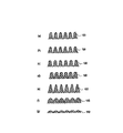
- FIG. 1 it is the schematic which shows the example of the shape of the fine euros
- FIG. 5 It is a partial expanded sectional view which shows an example of the antifouling coating which concerns on one Embodiment of the antifouling surface structure of this invention.
- the antifouling coating shown in FIG. 5 it is the schematic which shows a mode that the inner wall of a surface pore and dirt synovial fluid form a hydrogen bond and / or a covalent bond.
- FIG. 1 shows an antifouling film 200 according to an embodiment of the antifouling surface structure of the present invention.
- the antifouling film 200 includes a first layer 10 having a plurality of fine protrusions 100 on the surface, and a second layer 20 made of a metal oxide that covers the surface of the fine protrusions 100.
- the base material is composed of the layer 10 and the layer 20.
- the third layer 30 is disposed on the surface of the first layer 10 opposite to the surface on which the fine protrusions 100 are formed. Further, between the fine protrusions 100-100 covered with the second layer 20, a stain containing a compound having a functional group capable of hydrogen bonding and / or covalent bonding with the second layer 20 made of a metal oxide. Synovial fluid 60 is retained.
- compound means “soil lubricant”, and “soil lubricant” means a material having a function of sliding soils derived from any of water, oil, inorganic and organic systems.
- Liquid means a liquid material containing a soil lubricant.
- FIG. 2 shows that a soil lubricant 61 having a functional group capable of hydrogen bonding and / or covalent bonding forms a hydrogen bond and / or covalent bond 70 with the second layer 20 made of a metal oxide.
- covered is shown.
- the soil lubricant 60 contains a soil lubricant 61 having a functional group capable of hydrogen bonding and / or covalent bonding, but may also include a soil lubricant 62 having no functional group.
- the antifouling surface structure of the present invention is Expresses high liquid film retention.
- FIG. 2 also shows how the hydrogen bonding force 71 acts between the soil lubricants 61. Further, it also shows how the van der Waals force 80 acts between the dirt lubricants 61, between the dirt lubricants 62, and between the dirt lubricant 61 and the dirt lubricant 62.
- the hydrogen bonding force 71 and the van der Waals force 80 also contribute to the high liquid film retention of the antifouling surface structure of the present invention.
- a functional group which the soil lubricant 61 has a silanol group, an alkoxysilyl group, a chlorosilyl group, or an acetoxysilyl group can be mentioned, It is also possible to combine these functional groups by using multiple types of soil lubricants. It is.
- the dirt lubricant 61 and the dirt lubricant 62 constituting the dirt synovial fluid 60 are compounds containing a fluoroethylene chain in the molecular skeleton.
- the molecular skeleton of 61 and dirt lubricant 62 is desirably a fluoroether or a fluoroalkyl derivative.
- the molecular skeleton of the dirt lubricant 61 and the dirt lubricant 62 constituting the dirt synovial fluid 0 is more preferably a perfluoropolyether or a perfluoroalkyl derivative. That is, as a specific example of the soil lubricant 61, a derivative obtained by adding a functional group such as a silanol group, an alkoxysilyl group, a chlorosilyl group, or an acetoxysilyl group to a perfluoropolyether-based or perfluoroalkyl-based fluorine-based oil. Can be mentioned.
- specific examples of the dirt lubricant 62 include perfluoropolyether-based or perfluoroalkyl-based fluorine-based oils themselves.
- fluorine-based oils examples include Krytox (perfluoropolyether type) manufactured by Dupont, and DEMNUM S20 (perfluoropolyether type) manufactured by Daikin, which have a low vapor pressure ( ⁇ 0.01 Pa). It is suitable for holding because of its low volatility.
- the oil's evaporation loss is related to the long-term retention of these oils, it is preferable that the evaporation loss when heated at 121 ° C for 22 hours is less than 35%. If it exceeds 35%, the tips of the fine protrusions may be exposed during long-term use, and the sliding property of dirt and the durability of the structure may be deteriorated.
- the evaporation loss is evaluated by weighing the oil before and after heating. However, if the oil vapor pressure is known, the evaporation loss can be predicted.
- the kinetic viscosity of such a fluorinated oil at 20 ° C. is preferably 1 to 160 mm 2 / s. When it exceeds 160 mm 2 / s, the viscosity is too large, and the falling speed of dirt may decrease.
- the thickness is preferably 3 to 100 mm 2 / s, more preferably 15 to 80 mm 2 / s.
- Examples of the metal oxide constituting the second layer 20 include transparent inorganic materials such as silicon oxide, aluminum oxide and glass, silicon nitride, magnesium oxide, titanium oxide, indium oxide, tin oxide, cerium oxide, niobium oxide, Examples thereof include ceramic materials such as zirconium oxide, zinc oxide, ITO (indium-tin oxide), barium titanate and hafnium oxide.
- the soil synovial fluid 60 is composed only of the soil lubricant 61 having a functional group capable of forming a hydrogen bond and / or a covalent bond with the surface of the base material, a predetermined antifouling performance is exhibited.
- the ratio of the lubricant 61 is 0.1% by mass to 50% by mass, it is appropriate when more severe antifouling properties are required.
- the soil lubricant 61 having a functional group capable of hydrogen bonding and / or covalent bonding has a slightly lower water repellency than the soil lubricant 62 having no functional group.
- the soil lubricant 61 forms hydrogen bonds and / or covalent bonds 70 with the second layer 20 made of metal oxide, and the surface of the layer 20 is soil lubricant. 61.
- the remaining dirt lubricant 61 that did not contribute to the surface coating of the layer 20 floats in the dirt synovial fluid 60.
- the soil lubricant 61 having a functional group is slightly inferior in water repellency compared to the soil lubricant 62 having no functional group. Therefore, as the proportion of the soil lubricant 61 in the soil lubricant 60 increases, The amount of the soil lubricant 61 that has not contributed to the surface coating of 20 is increased, and the antifouling property is lowered.
- the dirt when the dirt is muddy water, if the ratio of the dirt lubricant 61 to the whole dirt synovial fluid is larger than 50%, the muddy water stops on the antifouling surface, and after drying and remaining on the surface, wipe it off with a cloth. Can be removed.
- the muddy water on the antifouling surface structure installed vertically can be easily removed, and in the range of 5 to 10%, most of the muddy water is installed at a small inclination angle. It is removed by sliding on the dirty surface structure.
- the antifouling surface having a small inclination angle of 5 ° or less can be slid down and removed up to muddy water of minute droplets having a diameter of about 1 to 2 mm.
- the fine protrusions 100 are formed in a frustum shape.
- a truncated cone shape such as a truncated cone and a truncated pyramid
- a truncated cone shape such as a cone and a pyramid
- the shape of the fine protrusion 100 is various, such as a deformed cone shape such as a bell shape or a real shape of a vertebra, a deformed pyramid shape having a curved side surface, a shape with a rounded tip, and a shape inclined from the center line.
- Various shapes can be used.
- FIG. 3 the example of the cross-sectional shape which the fine protrusion 100 in the antifouling water film of this invention can take is shown.
- a polygonal shape or a substantially circular shape is preferably used, but various other shapes such as a star shape and an elliptical shape can be used.
- a recess is formed between the fine protrusions 100. 101 may be provided.
- FIG. 4A when a surface B ′ passing through the bottom 102 of each recess 101 is assumed, the bottom 102 of the recess 101 surrounding the fine protrusion 100 in the surface B ′.
- the region partitioned by is defined as the bottom surface of the fine protrusion 100.
- FIG. 4B in the embodiment in which the root portion 103 of the fine protrusion 100 has a curved surface, similarly, a surface B ′ passing through the bottom 104 between the root portions 103 of the fine protrusion 100 is formed. Assuming that the region defined by the bottom 104 between the root portions 103 surrounding the fine protrusion 100 in the surface B ′ is defined as the bottom surface of the fine protrusion 100.
- the pitch A of each fine protrusion 100 is preferably preferably 50 ⁇ m or less in view of the structure of the film itself.
- the pitch A between the adjacent fine protrusions 100 exceeds 50 ⁇ m, the water repellent function is hardly exhibited effectively in various window panels using the film. That is, since the drizzle water droplets are about 50 ⁇ m, the water droplets enter the gaps between the fine protrusions, and the water droplets are difficult to move from the surface of the antifouling film.
- the surface of the second layer 20 formed on the fine protrusions 100 has a functional group capable of hydrogen bonding and / or covalent bonding, and has a fluoroethylene chain in the molecular skeleton. Since it is covered with the dirt lubricant 61 and the dirt lubricant 60 is held, it exhibits high water repellency and antifouling properties even when the pitch A exceeds 50 ⁇ m.
- the pitch A of each fine protrusion 100 refers to the distance between centroid points on the bottom surfaces of adjacent fine protrusions 100 as shown in FIGS.
- the pitch A of the fine protrusions 100 is preferably 380 nm or less. That is, the pitch A of the fine protrusions 100 is preferably a visible light wavelength of 380 to 750 nm or less. When the pitch A exceeds 380 nm, a part of visible light is diffused or diffracted by the fine protrusions 100, so that the light reflectance may increase. Note that the pitch A of the fine protrusions 100 is more preferably 150 nm or less. If the pitch A is 150 nm or less, the surface roughness is less than the average surface roughness of a human nail. Therefore, various window panels using the antifouling film effectively exhibit scratch resistance against nail scratching.
- the pitch A is desirably 380 nm or less, preferably 10 nm to 200 nm, more preferably 50 nm to 150 nm. If the pitch A exceeds 380 nm, the film may become cloudy, and the visibility of the part to which the film is attached and the clarity of the underlying material may be reduced.
- the height H of the fine protrusion 100 is essentially preferably 100 nm or more in view of the structure of the film itself. If the height H of the fine protrusion 100 is less than 100 nm, the antireflection effect may be reduced. On the other hand, if the height of the fine protrusion 100 is too large, breakage is likely to occur and the moldability may be lowered.
- the surface of the second layer 20 has a functional group capable of hydrogen bonding and / or covalent bonding, and molecules Since it is covered with a soil lubricant 61 having a fluoroethylene chain in its skeleton and further holds the soil synovial fluid 60, it exhibits high antifouling properties and water repellency even when the height H is less than 100 nm.
- the height H of the fine protrusion 100 is preferably 50 to 600 nm. If it is less than 50 nm, the retainability of the liquid 60 may be lowered, and if it exceeds 600 nm, the wear resistance may be deteriorated as described above.
- the height of the fine protrusion 100 means a distance in a direction perpendicular to the bottom surface B ′ from the bottom 104 of the fine protrusion 100 to the tip of the protrusion.
- the direction from the bottom (deepest part) 102 of the recess 101 to the tip of the protrusion is perpendicular to the bottom surface B ' Means distance.
- the fine protrusions 100 have a cone shape or a frustum shape (tapered shape) and are two-dimensionally arranged with a pitch A of 380 nm or less, fine irregularities on the surface are visible light. The size is unrecognizable. Therefore, color development due to light interference is eliminated, and it can be used as a transparent material. Moreover, since the reflection of scenery can be reduced by the antireflection effect, it can be suitably used for window panels of vehicles, ships, aircrafts, and the like.
- the size of the fine protrusion 100 in the antifouling film which is an example of the antifouling surface structure of the present invention is on the order of nanometers.
- the shape and pitch of the fine protrusions 100 are not perfect geometric shapes and vary to some extent due to manufacturing restrictions.
- the technical scope of the present invention is not limited at all.
- the antifouling film 200 of the present embodiment includes the first layer 10 having the plurality of fine protrusions 100, the second layer 20 that covers the entire surface of the fine protrusions 100, and is made of a metal oxide.
- the third layer 30 is disposed on the surface opposite to the fine protrusions 100 in the first layer 10.
- the elastic modulus of the first layer 10 is E1
- the elastic modulus of the second layer 20 is E2
- the elastic modulus of the third layer 30 is E3
- the relationship of E2>E1> E3 is satisfied.
- external input such as cloth wiping is roughly divided into input in the shear direction substantially along the surface of the first layer 10 and input in the compression direction substantially perpendicular to the surface.
- the second layer 20 has a higher elastic modulus E2 than that of the first layer 10, so that it is difficult to wear and further the shear input that propagates to the first layer 10 is applied. Relax and disperse.
- the first layer 10 has a lower elastic modulus E ⁇ b> 1 than the second layer 20, the shear input to the fine protrusions 100 is flexibly relaxed.
- the third layer 30 having an elastic modulus E3 lower than that of the first layer 10 mainly receives this input and elastically deforms, so that the fine protrusion 100 is destroyed. Suppress.
- the first layer 10 requires a certain level of elastic modulus E1 from the viewpoint of increasing the dimensional accuracy at the time of forming the fine protrusion 100 and protecting the fine protrusion 100 from claw scratching.
- the first layer 10 mainly bears elastic deformation with respect to the input in the compression direction, and the second layer The layer 20 is not elastically deformed so much.
- the amount of elastic deformation of the first layer 10 becomes relatively large, so that it is difficult to ensure wear resistance.
- the third layer 30 having an elastic modulus E3 lower than that of the first layer 10 exists on the surface of the first layer 10 opposite to the fine protrusions 100, the third layer 30 is elastically deformed. As a result, the amount of elastic deformation of the first layer 10 and the second layer 20 can be suppressed.
- the thickness T1 of the first layer 10 is preferably 1 to 30 ⁇ m. If the thickness of the first layer 10 is 1 ⁇ m or more, it is possible to suppress the occurrence of brittle fracture (cracking) of the first layer 10 even when the third layer 30 is deformed by the input in the compression direction. it can. Moreover, if the thickness of the 1st layer 10 is 30 micrometers or less, ensuring of curved surface followability at the time of applying the antifouling film 200 to the molded article which has a three-dimensional curved surface will become easy. Furthermore, it becomes easy to ensure moldability when using an active energy ray-curable resin as the material of the first layer 10.
- the film thickness T2 of the second layer 20 is not particularly limited as long as the shape of the fine protrusion 100 is not impaired, but if it is less than 5 nm, the surface cannot be uniformly treated, and the liquid film retainability may be lowered.
- Examples of the constituent material of the first layer 10 include non-crosslinked acrylic, crosslinked acrylic, crosslinked acrylic-urethane copolymer, crosslinked acrylic-elastomer copolymer, silicone elastomer, polyethylene, polypropylene, crosslinked polyvinyl alcohol, and polyvinylidene chloride. , Polyethylene terephthalate, polyvinyl chloride, polycarbonate, modified polyphenylene ether, polyphenylene sulfide, polyether ether ketone, liquid crystalline polymer, fluororesin, polyarate, polysulfone, polyethersulfone, polyamideimide, polyetherimide, thermoplastic polyimide, etc. Examples thereof include plastic resins, styrene elastomers such as polystyrene, urethane elastomers, silicone elastomers, and various gel materials.
- the soil lubricant 61 having a functional group capable of hydrogen bonding and / or covalent bonding is bonded to the second layer 20 made of metal oxide with hydrogen bonding and / or covalent bonding 70. And the surface of the layer 20 is coated.
- the surface of the second layer 20 made of a metal oxide may be subjected to water-repellent surface modification. That is, this surface modification prevents the formation of hydrogen bonds and / or covalent bonds 70, but the van der hour between the water repellent layer formed on the surface of the second layer 20 and the soil synovial fluid 60. This is because the soil synovial fluid 60 is held on the surface of the base material because the capillary force based on the Luss force acts.
- the second layer 20 may be omitted, and the first layer 10 itself may be composed of the above-described silicon oxide, aluminum oxide, or the like.
- Examples of the surface treatment material applied to the second layer 20 made of a metal oxide include fluorine-based surface modifiers such as fluoroalkylsilane and fluoropolyetheralkoxysilane, and silicone-based surface modifiers.
- the third layer 30 is bonded to the surface of the first layer 10 opposite to the fine protrusions 100. Furthermore, a pressure-sensitive adhesive can be applied to the surface of the third layer 30 opposite to the first layer 10 in accordance with the application.
- a pressure-sensitive adhesive can be applied to the surface of the third layer 30 opposite to the first layer 10 in accordance with the application.
- the elastic modulus E3 of the third layer 30 needs to be lower than the elastic modulus E1 of the first layer 10.
- the material used for the third layer 30 can be a general-purpose resin film, an engineering plastic film, or the like. Specifically, (meth) acrylic; polyolefins such as polyethylene and polypropylene; polycarbonates; polyesters such as polyethylene terephthalate (PET), polyethylene naphthalate (PEN), and fluorene derivatives; vinyl chloride; silicone; polyvinyl alcohol (PVA) ); Ethylene vinyl acetate copolymer (EVA); cellulose; amide-based films can be used. Further, when a water repellent film is used at a site where transparency is required, a transparent third layer is selected.
- the material for the transparent third layer is preferably (meth) acryl; polycarbonate; PET, and more preferably (meth) acryl and PET.
- the third layer 30 has a role of supplementing the rigidity and film strength of the first layer 10 when the thickness of the first layer 10 is such that brittleness does not appear. Further, by setting the elastic modulus lower than that of the first layer, the third layer is more easily deformed than the first layer with respect to the external input in the compression direction, and the effect of relaxing the input applied to the fine protrusions 100. There is.
- the thickness T3 of the third layer 30 is not particularly limited as long as it follows a three-dimensional curved surface or can be molded.
- the thickness T ⁇ b> 3 of the third layer 30 is preferably thicker than the thickness of the first layer 10.
- the third layer 30 is more easily deformed than the first layer 10, and the input in the compression direction applied to the fine protrusions 100 can be relaxed.
- the thickness T3 of the third layer 30 is preferably about 20 to 250 ⁇ m, more preferably 25 to 200 ⁇ m, most preferably 25 to 70 ⁇ m. preferable.
- the thickness T3 of the third layer 30 is in the range of 20 to 200 ⁇ m, the amount of displacement of the third layer 30 when a load in the compression direction is input to the antifouling film 200 can be suppressed to a reasonably small value. Therefore, there is no contact of the friction piece at the time of friction input, the load is evenly distributed, and the fine protrusion 100 is not easily worn.
- the elastic modulus E3 of the third layer 30 is at most about 6 GPa in consideration of the above-described material types, and therefore, with respect to displacement, the thickness change of the third layer 30 is more than the first layer 10. Great effect.
- the breaking elongation ⁇ max of the third layer 30 may be 50% or more. preferable.
- the upper limit of the breaking elongation ⁇ max of the third layer 30 is not particularly limited, but can be 500% or less.
- the parts or products (molded articles) provided with the antifouling surface structure of the present invention are the frontmost parts such as automobile and motorcycle meter panels and wind panels, mobile devices such as mobile phones and electronic notebooks, signboards and watches. It is suitably used for a display device that may be exposed to water such as rain or oil stains.
- the form of the display device is not particularly limited, and for example, a system combining mechanical display and illumination such as an analog meter can be given.
- liquid crystal, light emitting diode (LED), electroluminescence (EL) and other backlights and light emitting surfaces such as digital meters and monitors, and reflective liquid crystal such as mobile devices. Can be mentioned.
- UV absorbers antioxidants, radical scavengers, etc. are applied to the first layer and the third layer. It can be added. Further, a bluing agent or a fluorescent coloring pigment for compensating for yellowing due to deterioration of the resin can be used.
- the antifouling film which is an example of the antifouling surface structure of the present invention, is only applied to exterior parts such as painted surfaces of automobiles, glass windows, camera lenses, door mirrors, lamps, and door knobs in addition to the above parts. Therefore, it is also easy to provide a part having an excellent antifouling surface. For example, if it is applied to automobile coating, it is considered that the need for car washing is eliminated over a long period of time. Moreover, if it is applied to an in-vehicle camera, a clear field of view can be secured even in rainy weather or on bad roads. In addition, it can be used for mirrors, radiator fins, evaporators, and the like, and is considered to bring various advantages.
- FIG. 5 shows an antifouling coating 300 according to one embodiment of the antifouling surface structure of the present invention.
- the antifouling coating 300 has a plurality of pores 21 on the surface and includes a layer 20 made of a metal oxide.
- the surface roughness Ra of the layer 20 is 400 nm or less, and a dirt synovial fluid 60 containing a dirt lubricant having a functional group capable of hydrogen bonding and / or covalent bonding is held in the pores 21.
- the pores 21 of the layer 20 may be independent holes or communication holes opened on the surface.
- the layer 20 is formed on the surface of the base material 40, but the layer 20 itself may be the base material.
- FIG. 6 shows that the dirt lubricant 61 having a functional group capable of hydrogen bonding and / or covalent bonding is bonded to the inner wall of the pore 21 of the coating film 20 made of metal oxide with hydrogen bonding and / or covalent bonding 70. And a state in which the inner wall of the pore 21 is covered is shown.
- the soil lubricant 60 contains a soil lubricant 61 having a functional group capable of hydrogen bonding and / or covalent bonding, but may also include a soil lubricant 62 having no functional group.
- the antifouling coating of this embodiment is formed. Expresses high liquid film retention.
- FIG. 6 also shows how the hydrogen bonding force 71 works between the soil lubricants 61. Further, the manner in which the van der Waals force 80 acts between the dirt lubricants 61, between the dirt lubricants 62, and between the dirt lubricant 61 and the dirt lubricant 62 is also shown. The hydrogen bonding force 71 and van der Waals force 80 also contribute to the high liquid film retention of the antifouling surface structure of the present invention.
- the functional group of the dirt lubricant 61 includes a silanol group, an alkoxysilyl group, a chlorosilyl group, an acetoxysilyl group, and any combination thereof.
- the dirt lubricants 61 and 62 constituting the dirt synovial fluid 60 include a fluoroethylene chain in the molecular skeleton.
- the dirt lubricant 61 constituting the dirt lubricant 60 and The molecular skeleton of 62 is desirably a fluoroether or fluoroalkyl derivative.
- the molecular skeleton of the soil lubricants 61 and 62 constituting the soil lubricant 60 is more preferably a perfluoropolyether or a perfluoroalkyl derivative. That is, the dirt lubricant 61 is a derivative obtained by adding a functional group such as a silanol group, an alkoxysilyl group, a chlorosilyl group, or an acetoxysilyl group to a perfluoropolyether-based or perfluoroalkyl-based fluorine oil. Further, the dirt lubricant 62 is a perfluoropolyether-based or perfluoroalkyl-based fluorine oil itself.
- fluorine-based oils examples include Krytox (perfluoropolyether-based) manufactured by Dupont and DENNUM S20 (perfluoropolyether-based) manufactured by Daikin, which have a low vapor pressure ( ⁇ 0.01 Pa). ) Low volatility, suitable for holding.
- fluorinert perfluoroalkyl type
- Novec perfluoropolyether type
- the side chain may have a functional group having a halogen element other than fluorine or a halogen other than fluorine.
- the long-term retention of these oils is related to the loss of evaporation of the oil, and it is preferable that the evaporation loss when heated at 121 ° C. for 22 hours is less than 35%. If it exceeds 35%, the above-mentioned pores and inner walls may be exposed in long-term use, and the sliding property of dirt and the durability of the structure may be deteriorated.
- the evaporation loss is evaluated by weighing the oil before and after heating. However, if the oil vapor pressure is known, the evaporation loss can be predicted.
- the kinematic viscosity of the oil at 20 ° C. is preferably 1 to 160 mm 2 / s due to dirt slipping property. If it exceeds 160 mm 2 / s, the viscosity is too large and the sliding speed of dirt may be reduced.
- the thickness is preferably 3 to 100 mm 2 / s, more preferably 15 to 80 mm 2 / s.
- the metal oxide which comprises the layer 20 is not specifically limited, Preferably, the silicon oxide, titanium oxide, zirconium oxide, tin oxide, aluminum oxide, indium tin oxide, zinc oxide which can ensure high transparency and abrasion resistance are preferable. And inorganic oxides such as zinc tin oxide and magnesium oxide, and transparent inorganic materials such as magnesium fluoride and glass. Further, the material forming the layer 20 is preferably one having a modulus of elasticity of 20 GPa or more by the nano-indent method among the above from the viewpoint of durability. More preferably, it is 50 GPa or more.
- the soil synovial fluid 60 is composed only of the soil lubricant 61 having a functional group capable of forming a hydrogen bond and / or a covalent bond with the substrate surface, a predetermined antifouling performance is exhibited.
- the ratio of the dirt lubricant 61 is 0.1 mass% or more and 50 mass% or less, it is appropriate when more severe antifouling properties are required.
- the soil lubricant 60 has a ratio of the soil lubricant 61 to the entire liquid of 0.1% by mass or more and 10% by mass or less. More preferably, in the soil synovial fluid 60, the ratio of the soil lubricant 61 to the entire liquid is 0.1% by mass or more and 5% by mass or less.
- the soil lubricant 61 having a functional group capable of hydrogen bonding and / or covalent bonding has a slightly lower water repellency than the soil lubricant 62 having no functional group.
- the dirt lubricant 61 forms hydrogen bonds and / or covalent bonds 70 with the inner walls of the pores 21 of the layer 20 made of metal oxide, and the inner walls of the pores 21 are covered with the dirt lubricant 61. At this time, the remaining dirt lubricant 61 that did not contribute to the surface coating of the inner walls of the pores 21 floats in the liquid 60.
- the soil lubricant 61 having a functional group has a slightly lower water repellency than the soil lubricant 62 having no functional group. Therefore, as the ratio of the soil lubricant 61 in the soil lubricant 60 increases, The amount of the soil lubricant 61 that has not contributed to the surface coating of the inner wall of the pore 21 is increased, and the antifouling property is lowered.
- Ra surface roughness of 400 nm or less, preferably 300 nm or less, more preferably 200 nm or less, from the viewpoint of optical properties and wear resistance. If Ra exceeds 400 nm, light is likely to be scattered, making it difficult to apply to parts that require high transparency, and the structure being liable to be destroyed by the fact that sliding objects are caught on the surface roughness. .
- the method for forming the layer 20 is not particularly limited, but various methods such as a sol-gel method, CVD, vapor deposition, and magnetron sputtering can be used.
- the sol-gel method is preferably used because the pore size can be easily adjusted by adjusting the phase separation agent and reaction rate.
- the inner diameter D (see FIG. 5) of the pores 21 of the layer 20 needs to be 400 nm or less because light scattering is particularly strong from the relationship of optical characteristics, and it is precisely D so that visible light diffraction does not occur. It is desirable that ⁇ 400 nm / n (n is the refractive index of the constituent material). Furthermore, the lower limit value of the inner diameter D of the pore 21 is preferably larger than the molecule of the liquid to be introduced. For example, the molecular length of the Kfluorox series (manufactured by DuPont) perfluoropolyether oil is about 10 to 50 nm. Therefore, the lower limit is about 10 nm.
- Parts or products (molded articles) having an antifouling coating as an example of the antifouling surface structure of the present invention include, for example, automobile and motorcycle meter panels, wind panels, mobile devices such as mobile phones and electronic notebooks, and signboards. Moreover, it is suitably used for a display device such as a watch that may be exposed to water or oil stains such as rain in the foreground.
- the format of the display device is not particularly limited, and for example, a system combining mechanical display and illumination such as an analog meter can be used.
- liquid crystal light emitting diode (LED), electroluminescence (EL) and other backlights and light emitting surfaces such as digital meters and monitors, and reflective liquid crystal such as mobile devices.
- LED light emitting diode
- EL electroluminescence
- other backlights and light emitting surfaces such as digital meters and monitors
- reflective liquid crystal such as mobile devices.
- it can be used for mirrors, radiator fins, evaporators, and the like, and is considered to bring various advantages.
- TAC acetylcellulose
- an ultraviolet curable monomer Mitsubishi Rayon Co., Ltd .: Diabeam MP-141
- a mold for forming fine projections having a truncated cone shape and a hexagonal close-packed pattern with a pitch of 100 nm and a height of 200 nm was pressed against the monomer, and ultraviolet irradiation was performed from the third layer 30 side to cure the monomer.
- the film was peeled off from the mold, and fine projection films of respective examples having the fine projections shown in Table 1 on the first layer were produced.
- the surface treatment of the obtained fine projection film was performed under the conditions shown in Table 1, and the second layer 20 was formed.
- the silicon oxide of the adhesion layer was formed by reactive sputtering in which silicon was oxidized while sputtering from a silicon target.
- a fluorine compound layer was formed on the surface of the second layer 20.
- the fluorine compound layer was formed by vapor deposition of perfluoropolyetheralkoxysilane.
- Daikin Optool DSX (trade name) was used as the soil lubricant 61
- DENNUM S20 (trade name) manufactured by Daikin was used as the soil lubricant 62.
- the film thickness of the dirt synovial fluid 60 was calculated
- Examples 1 to 5 are superior to Comparative Example 1.
- Examples 4 and 5 are not good when comparing the water droplet sliding properties.
- Examples 1 to 3 in which the amount of the soil lubricant 61 having a functional group added is 50% by mass or less include almost all cases including severe applications in which minute water droplets such as camera lenses impede visibility. Can be used for applications.
- the application object of Example 4 and 5 in which the addition amount of the soil lubricant 61 having a functional group is 95% by mass or more is appropriate for purposes other than the use such as a camera lens in which minute water droplets obstruct visibility.
- Liquid film thickness retention Maintaining the liquid film thickness based on the change rate of the film thickness of the dirt synovial fluid 60 before and after the spinner high-speed rotation (5000 rpm ⁇ 5 min), using the sample with the surface of the fine projection film affixed to the glass plate as the sample. The rate was measured.
- the liquid film thickness retention ratio R was R ⁇ 75%, ⁇ , when 50 ⁇ R ⁇ 75, ⁇ , when 30 ⁇ H ⁇ 50, ⁇ , and when H ⁇ 30, ⁇ .
- the contact angle was measured using DSA100 (manufactured by Kruss) with a drop water droplet volume of 5 ⁇ L, and the static contact angle was derived by ⁇ / 2 approximation.
- [Anti-fouling evaluation] [Large water droplet sliding properties] 20 ⁇ L of water was dropped on the test piece. If the sliding angle was 10 ° or less, ⁇ if 10 ° to 15 °, ⁇ if 15 ° to 30 °, and x if more than 30 °. [Oil drop slidability] 20 ⁇ L of oleic acid was dropped onto the test piece. If the sliding angle was 10 ° or less, ⁇ if 10 ° to 15 °, ⁇ if 15 ° to 30 °, and ⁇ if more than 30 °. [Small water drop sliding properties] 1 ⁇ L of water was placed on a test piece placed vertically, and the vertical sliding speed of minute water droplets was measured. ⁇ if the sliding speed is 2.5 mm / sec or more, ⁇ if the sliding speed is 1.5 to 2.5 mm / sec, ⁇ if 0.3 to 1.5 mm / sec, ⁇ 0.3 mm / sec or less. It was.
- Examples 6 to 10 and Comparative Example 2 [Preparation of coating with pores]
- a solution having the following formulation was coated on glass by spin coating (2000 rpm, 20 sec), and placed in an oven at an atmospheric temperature of 150 ° C. within 1 minute to perform temporary curing for 1 hour. Then, the sample after temporary hardening was baked at 450 degreeC for 1 hour, and the glass plate which has the porous layer 20 which has a communicating hole was produced.
- a fluorine layer was formed on the surface of the porous layer 20 produced above.
- the porous layer 20 was prepared by immersing the glass plate having the porous layer 20 produced above in Fluorosurf (Fluoro Technology, PFPE 0.1%) for 24 hours and drying at 150 ° C. for 1 hour four times. A fluorine layer was formed on the surface of 20 as Comparative Example 2.
- Examples 6 to 10 are superior to Comparative Example 2.
- Examples 9 and 10 are not good when comparing the water droplet sliding properties. From the above, Examples 6 to 8 in which the amount of the soil lubricant 61 having a functional group is 50% by mass or less include almost all cases including severe applications in which minute water droplets such as camera lenses obstruct the field of view. Can be used for Further, the application destination of Examples 9 and 10 in which the addition amount of the soil lubricant 61 having a functional group is 95% by mass or more is suitable for purposes other than the use such as a camera lens in which minute water droplets obstruct visibility.
- Liquid film thickness retention A sample obtained by applying the stain synovial fluid 60 to the surface of the glass plate was used as a sample, and the liquid film thickness retention rate was measured based on the film thickness change rate of the liquid 60 before and after high-speed spinner rotation (5000 rpm ⁇ 5 min).
- the liquid film thickness retention ratio R was R ⁇ 75%, ⁇ , when 50 ⁇ R ⁇ 75, ⁇ , when 30 ⁇ H ⁇ 50, ⁇ , and when H ⁇ 30, ⁇ .
- the contact angle was measured using DSA100 (manufactured by Kruss) with a drop water droplet volume of 5 ⁇ L, and the static contact angle was derived by ⁇ / 2 approximation.
- [Anti-fouling evaluation] [Large water droplet sliding properties] 20 ⁇ L of water was dropped on the test piece. If the sliding angle was 10 ° or less, ⁇ if 10 ° to 15 °, ⁇ if 15 ° to 30 °, and x if more than 30 °. [Oil drop slidability] 20 ⁇ L of oleic acid was dropped onto the test piece. If the sliding angle was 10 ° or less, ⁇ if 10 ° to 15 °, ⁇ if 15 ° to 30 °, and ⁇ if more than 30 °. [Small water drop sliding properties] 1 ⁇ L of water was placed on a test piece placed vertically, and the vertical sliding speed of minute water droplets was measured. ⁇ if the sliding speed is 2.5 mm / sec or more, ⁇ if the sliding speed is 1.5 to 2.5 mm / sec, ⁇ if 0.3 to 1.5 mm / sec, ⁇ 0.3 mm / sec or less. It was.
- the number of times a car is washed can be greatly reduced, and if it is applied to an in-vehicle camera, a mirror, a window, etc., a clear field of view can be secured even in rainy weather or on a rough road.
- a clear field of view can be secured even in rainy weather or on a rough road.
- Base material 60 Dirt synovial fluid 61 Dirt lubricant with functional group 62 Dirt lubricant without functional group 70, 71 Hydrogen bond Force and / or covalent bonding force 80 Van der Waals force 100 Fine protrusion 200 Antifouling film 300 Antifouling coating
Landscapes
- Engineering & Computer Science (AREA)
- Mechanical Engineering (AREA)
- Laminated Bodies (AREA)
- Paints Or Removers (AREA)
Abstract
防汚性表面構造は、微細凹凸構造を有する基材と、この基材に保持された汚れ滑液を備えた防汚性表面構造体である。汚れ滑液が汚れ滑剤を含み、基材の表面と上記汚れ滑剤の少なくとも1種が、水素結合及び/又は共有結合によって結合している。水素結合及び/又は共有結合が、シラノール基、アルコキシシリル基、クロロシリル基及びアセトキシシリル基から成る群より選ばれた少なくとも1種の官能基によって形成されている。基材の表面に金属酸化物層を有するか又は基材自体が金属酸化物で形成されている。 自動車部品はこのような防汚性表面構造体を備える。
Description
本発明は、建造物や自動車、食品容器及び医療用具など様々な分野での汚れ付着を防ぎ、建物や自動車等では外観や視認性の向上を長期にわたって実現し得る防汚性表面に関する。
更に詳細には、微細凹凸構造を有する基材に所定の液体を保持させた防汚性表面、及びこの防汚性表面が形成された自動車部品に関するものである。
更に詳細には、微細凹凸構造を有する基材に所定の液体を保持させた防汚性表面、及びこの防汚性表面が形成された自動車部品に関するものである。
従来、防汚性表面として一般的に利用されているフッ素系材料でコーティングした表面は、表面自由エネルギーが小さく、様々な汚れの付着を防止できる。
しかし、フッ素は分子内での極性が大きいため、汚れの種類によっては却って付着性が強くなるものもあった。また、ピッチやタール、樹液などの高粘性の汚れは付着性が強く、フッ素系材料でコーティングした表面でも固着することが知られている。
しかし、フッ素は分子内での極性が大きいため、汚れの種類によっては却って付着性が強くなるものもあった。また、ピッチやタール、樹液などの高粘性の汚れは付着性が強く、フッ素系材料でコーティングした表面でも固着することが知られている。
防汚のもう一つの方策として、表面を超親水性にすることにより、水を流したときに汚れと親水性表面の間に水を浸入させて汚れを剥離するものがある。この方策はカタツムリの殻を模倣したものであり、特許文献1のような先行技術が知られている。
この一方で、非特許文献1には、表面にフッ素液体を保持させることで、様々な汚れを滑落させる技術が報告されている。
この一方で、非特許文献1には、表面にフッ素液体を保持させることで、様々な汚れを滑落させる技術が報告されている。
Tak-Sing Wong,Bioinspired self-repairing slippery surfaces with pressure-stable omniphobicity,NATURE 477 443-447(2011)
しかしながら、特許文献1に記載されているような技術にあっては、超親水性表面ゆえ、水と表面自由エネルギーが近い水垢などの汚れは付着してしまう。
実際に、カタツムリの殻や住宅外壁材では光沢が無いため、少々の水垢や水シミ付着ではほとんど目立たないが、自動車塗装のように光沢が意匠性の主要な構成要素である用途への応用は非常に困難である。
実際に、カタツムリの殻や住宅外壁材では光沢が無いため、少々の水垢や水シミ付着ではほとんど目立たないが、自動車塗装のように光沢が意匠性の主要な構成要素である用途への応用は非常に困難である。
一方、非特許文献1に記載されているような技術にあっては、依然として学術的な領域の研究であり、実際の耐久性や透明性などにおいて実用できる分野が限定される。
本発明は、このような従来技術の有する課題に鑑みてなされたものであり、その目的とするところは、自動車分野などの過酷な耐久性を要求される分野において、長期間の耐久性と防汚性を両立し得る防汚性表面を提供することにある。
本発明者は、上記目的を達成すべく鋭意検討を重ねた結果、微細凹凸構造を有する基材と汚れ滑液を併用することなどにより、上記目的が達成できることを見出し、本発明を完成するに至った。
即ち、本発明の防汚性表面構造体は、微細凹凸構造を有する基材と、この基材に保持された汚れ滑液を備えた防汚性表面構造体である。
上記汚れ滑液が汚れ滑剤を含み、
上記基材の表面と上記汚れ滑剤の少なくとも1種が、水素結合及び/又は共有結合によって結合していることを特徴とする。
上記汚れ滑液が汚れ滑剤を含み、
上記基材の表面と上記汚れ滑剤の少なくとも1種が、水素結合及び/又は共有結合によって結合していることを特徴とする。
また、本発明の自動車部品は、上述の如き防汚性表面構造体を備えることを特徴とする。
本発明によれば、微細凹凸構造を有する基材と汚れ滑液を併用することなどとしたため、自動車分野などの過酷な耐久性を要求される分野において、長期間の耐久性と防汚性を両立し得る防汚性表面を提供することができる。
このように、本発明の防汚性表面構造体においては、汚れ滑液中の汚れ滑剤の少なくとも1種が基材表面に、水素結合力及び/又は共有結合力によって強固に保持される。
これに対し、非特許文献1に記載されているような従来の技術にあっては、水素結合力や共有結合力よりも弱い結合力であるファンデアワールス力によって、フッ素液体が基材表面に保持されているため、本発明の防汚表面構造体よりも潤滑液膜(フッ素液体)の保持性に劣っている。
これに対し、非特許文献1に記載されているような従来の技術にあっては、水素結合力や共有結合力よりも弱い結合力であるファンデアワールス力によって、フッ素液体が基材表面に保持されているため、本発明の防汚表面構造体よりも潤滑液膜(フッ素液体)の保持性に劣っている。
また、非特許文献1に記載されているような従来の技術にあっては、あらかじめ基材表面にフッ素化合物層が形成されており、このフッ素化合物層が摩耗によって欠落すると、防汚性能が低下し又は消失するという問題があった。
これに対し、本発明の防汚表面構造体では、基材表面と水素結合及び/又は共有結合を形成する官能基を有する化合物(汚れ滑剤の少なくとも1種)が、当該結合形式によって基材表面と結合して被覆層を形成し、これが防汚性発現の一因となる。
そして、上記の被覆層及び/又は基材表面が摩耗によって欠落した場合であっても、上記官能基を持つ化合物が、再び基材表面と結合して被覆層を再生して防汚性を発現するため、防汚性能の低下を抑制できる。
これに対し、本発明の防汚表面構造体では、基材表面と水素結合及び/又は共有結合を形成する官能基を有する化合物(汚れ滑剤の少なくとも1種)が、当該結合形式によって基材表面と結合して被覆層を形成し、これが防汚性発現の一因となる。
そして、上記の被覆層及び/又は基材表面が摩耗によって欠落した場合であっても、上記官能基を持つ化合物が、再び基材表面と結合して被覆層を再生して防汚性を発現するため、防汚性能の低下を抑制できる。
本発明の防汚表面構造体は、上述のような比較的強固な結合力による被覆層の形成機能とその再生機能を有するものであり、自動車分野などの過酷な耐久性を要求される分野において、長期間の防汚性と耐久性を両立し得る防汚性表面を提供できるものである。
以下、本発明の防汚性表面構造体につき、防汚フィルム及び防汚コーティングを例とし、併せてこれらを備えた自動車用部品について、図面を用いて詳細に説明する。
なお、図面の寸法比率は説明の都合上誇張されており、実際の比率とは異なる場合がある。また、本明細書において、濃度及び含有量等についての「%」は特記しない限り質量百分率を表すものとする。
なお、図面の寸法比率は説明の都合上誇張されており、実際の比率とは異なる場合がある。また、本明細書において、濃度及び含有量等についての「%」は特記しない限り質量百分率を表すものとする。
[防汚フィルム]
図1は、本発明の防汚性表面構造体の一実施形態に係る防汚フィルム200を示す。
防汚フィルム200は、表面に複数の微細突起100を有する第1の層10と、微細突起100の表面を被覆する金属酸化物から成る第2の層20とを備えている。なお、本実施形態においては、層10と層20で基材が構成されている。
図1は、本発明の防汚性表面構造体の一実施形態に係る防汚フィルム200を示す。
防汚フィルム200は、表面に複数の微細突起100を有する第1の層10と、微細突起100の表面を被覆する金属酸化物から成る第2の層20とを備えている。なお、本実施形態においては、層10と層20で基材が構成されている。
また、第1の層10における微細突起100が形成された面と反対側の面には、第3の層30が配置されている。さらに、第2の層20で被覆された微細突起100-100間には、金属酸化物から成る第2の層20と水素結合及び/又は共有結合が可能な官能基を持つ化合物を含有する汚れ滑液60が保持されている。
ここで、「化合物」は「汚れ滑剤」を意味し、「汚れ滑剤」は水系、油系、無機物系及び有機物系のいずれに由来する汚れでも滑らせる機能を有する材料を意味し、「汚れ滑液」は汚れ滑剤を含み液体状をなす材料を意味している。
ここで、「化合物」は「汚れ滑剤」を意味し、「汚れ滑剤」は水系、油系、無機物系及び有機物系のいずれに由来する汚れでも滑らせる機能を有する材料を意味し、「汚れ滑液」は汚れ滑剤を含み液体状をなす材料を意味している。
図2は、水素結合及び/又は共有結合が可能な官能基を持つ汚れ滑剤61が、金属酸化物から成る第2の層20との間に、水素結合及び/又は共有結合70を形成し、層20の表面を被覆する様子を示す。
なお、汚れ滑液60は、水素結合及び/又は共有結合が可能な官能基を持つ汚れ滑剤61を含有するが、上記官能基を持たない汚れ滑剤62を含んでもかまわない。
このように、金属酸化物から成る第2の層20と、汚れ滑液60との間には、水素結合及び/又は共有結合が形成されるために、本発明の防汚性表面構造体は、高い液膜保持性を発現する。
なお、汚れ滑液60は、水素結合及び/又は共有結合が可能な官能基を持つ汚れ滑剤61を含有するが、上記官能基を持たない汚れ滑剤62を含んでもかまわない。
このように、金属酸化物から成る第2の層20と、汚れ滑液60との間には、水素結合及び/又は共有結合が形成されるために、本発明の防汚性表面構造体は、高い液膜保持性を発現する。
また、図2は、汚れ滑剤61同士間に水素結合力71も働く様子も示す。さらに、汚れ滑剤61同士間、汚れ滑剤62同士間、及び汚れ滑剤61と汚れ滑剤62との間に、ファンデアワールス力80が働く様子も示している。
このように、本発明の防汚性表面構造体の高い液膜保持性には、上記水素結合力71及びファンデアワールス力80も寄与している。
このように、本発明の防汚性表面構造体の高い液膜保持性には、上記水素結合力71及びファンデアワールス力80も寄与している。
なお、汚れ滑剤61が持つ官能基としては、シラノール基、アルコキシシリル基、クロロシリル基又はアセトキシシリル基を挙げることができ、複数種の汚れ滑剤を用いることにより、これらの官能基を組み合わせることも可能である。
また、本発明においては特に限定されるものではないが、本実施形態において、汚れ滑液60を構成する汚れ滑剤61及び汚れ滑剤62は、分子骨格にフルオロエチレン鎖を含む化合物である。
なお、汚れ滑剤61の官能基を除いた主鎖、及び官能基を持たない汚れ滑剤62の表面自由エネルギーが低い程、優れた防汚性能が発現するので、汚れ滑液60を構成する汚れ滑剤61及び汚れ滑剤62の分子骨格は、望ましくはフルオロエーテル又はフルオロアルキルの誘導体である。
また、汚れ滑液0を構成する汚れ滑剤61及び汚れ滑剤62の分子骨格については、パーフルオロポリエーテル又はパーフロオロアルキルの誘導体とすることがさらに望ましい。
即ち、汚れ滑剤61の具体例としては、パーフルオロポリエーテル系又はパーフロオロアルキル系のフッ素系オイルに、シラノール基、アルコキシシリル基、クロロシリル基又はアセトキシシリル基のような官能基が付与された誘導体を挙げることができる。
一方、汚れ滑剤62の具体例としては、パーフルオロポリエーテル系又はパーフロオロアルキル系のフッ素系オイル、そのものを例示できる。
即ち、汚れ滑剤61の具体例としては、パーフルオロポリエーテル系又はパーフロオロアルキル系のフッ素系オイルに、シラノール基、アルコキシシリル基、クロロシリル基又はアセトキシシリル基のような官能基が付与された誘導体を挙げることができる。
一方、汚れ滑剤62の具体例としては、パーフルオロポリエーテル系又はパーフロオロアルキル系のフッ素系オイル、そのものを例示できる。
かかるフッ素系のオイルとしては、Dupont社製のKrytox(パーフルオロポリエーテル系)、ダイキン社製のDEMNUM S20(パーフルオロポリエーテル系)などがあり、これらは蒸気圧が低く(≦0.01Pa)、揮発性が低いので保持に適している。
その他には、3M社製のフロリナート(パーフルオロアルキル系)やノベック(パーフルオロポリエーテル系)などがあるが、揮発性が高いので短期的な使用にすることが好ましい。これらのオイルの粘度や蒸気圧を調整するため、側鎖にフッ素以外のハロゲン元素又はフッ素以外のハロゲンを有する官能基を付与することもある。
これらのオイルの長期的な保持性にはオイルの蒸発減量も関係するが、121℃で22時間加熱した際の蒸発減量が35%未満のものが好ましい。35%を超えると、長期使用において微細突起先端部が露出し、汚れの滑落性や構造の耐久性が低下することがある。
この蒸発減量については、オイルを加熱前後で秤量して評価するが、オイルの蒸気圧がわかれば蒸発減量を予測することも可能である。
この蒸発減量については、オイルを加熱前後で秤量して評価するが、オイルの蒸気圧がわかれば蒸発減量を予測することも可能である。
かかるフッ素系オイルの20℃における動粘度としては1~160mm2/sが良好でである。
160mm2/sを超えると粘性が大きすぎて汚れの転落速度が低下することがある。好ましくは3~100mm2/s、さらに好ましくは、15~80mm2/sである。
160mm2/sを超えると粘性が大きすぎて汚れの転落速度が低下することがある。好ましくは3~100mm2/s、さらに好ましくは、15~80mm2/sである。
第2の層20を構成する金属酸化物としては、例えば、酸化ケイ素、酸化アルミニウム及びガラス等の透明無機材料、窒化ケイ素、酸化マグネシウム、酸化チタン、酸化インジウム、酸化スズ、酸化セリウム、酸化ニオブ、酸化ジルコニウム、酸化亜鉛、ITO(インジウム-錫酸化物)、チタン酸バリウム及び酸化ハフニウムなどのセラミック材料等を挙げることができる。
汚れ滑液60は、基材表面と水素結合及び/又は共有結合が形成可能な官能基を有する汚れ滑剤61のみで構成しても所定の防汚性能が発現するが、汚れ滑液全体に対する汚れ滑剤61の割合が0.1質量%~50質量%である場合には、より厳しい防汚性が要求される場合に適切である。
更に厳しい防汚性が要求される場合は、汚れ滑液60は、液体全体に対する汚れ滑剤61の割合を0.1質量%~10質量%にすることが望ましい。
更に望ましくは、汚れ滑液60は、液体全体に対する汚れ滑剤61の割合を0.1質量%~5質量%とする。
更に厳しい防汚性が要求される場合は、汚れ滑液60は、液体全体に対する汚れ滑剤61の割合を0.1質量%~10質量%にすることが望ましい。
更に望ましくは、汚れ滑液60は、液体全体に対する汚れ滑剤61の割合を0.1質量%~5質量%とする。
ここで、その理由を簡単に説明する。
即ち、水素結合及び/又は共有結合が可能な官能基を持つ汚れ滑剤61は、該官能基を持たない汚れ滑剤62に比べると、撥水性が若干劣るため、汚れ滑液60の中の汚れ滑剤61の割合が大きい程、防汚性は低下することになる。
即ち、水素結合及び/又は共有結合が可能な官能基を持つ汚れ滑剤61は、該官能基を持たない汚れ滑剤62に比べると、撥水性が若干劣るため、汚れ滑液60の中の汚れ滑剤61の割合が大きい程、防汚性は低下することになる。
図2を用いて、更に詳しく説明すると、汚れ滑剤61は、金属酸化物から成る第2の層20との間に、水素結合及び/又は共有結合70を形成し、層20の表面は汚れ滑剤61で被覆される。この際、層20の表面被覆に寄与しなかった残りの汚れ滑剤61は汚れ滑液60の中を浮遊する。
上述のとおり、官能基を持つ汚れ滑剤61は、官能基を持たない汚れ滑剤62に比べると、撥水性が若干劣るので、汚れ滑液60の中の汚れ滑剤61の割合が大きくなる程、層20の表面被覆に寄与しなかった汚れ滑剤61が多くなり、防汚性は低下する。
上述のとおり、官能基を持つ汚れ滑剤61は、官能基を持たない汚れ滑剤62に比べると、撥水性が若干劣るので、汚れ滑液60の中の汚れ滑剤61の割合が大きくなる程、層20の表面被覆に寄与しなかった汚れ滑剤61が多くなり、防汚性は低下する。
例えば、汚れが泥水の場合、汚れ滑液全体に対する汚れ滑剤61の割合が50%よりも大きな場合は、泥水が防汚性表面に止まり、乾燥して表面に残存後も布などで軽く拭き取るだけで除去が可能である。
10~50%の範囲では垂直に設置した防汚性表面構造体上の泥水が容易に滑落除去されるようになり、さらに5~10%の範囲では大半の泥水が小さな傾斜角度で設置した防汚性表面構造体上で滑落除去される。5%以下となると、直径1~2mm程度の微小液滴の泥水まで5°以下の小さな傾斜角の防汚性表面を滑落除去されるようにすることができる。
10~50%の範囲では垂直に設置した防汚性表面構造体上の泥水が容易に滑落除去されるようになり、さらに5~10%の範囲では大半の泥水が小さな傾斜角度で設置した防汚性表面構造体上で滑落除去される。5%以下となると、直径1~2mm程度の微小液滴の泥水まで5°以下の小さな傾斜角の防汚性表面を滑落除去されるようにすることができる。
次に、微細突起100の形態について詳述する。
即ち、図1に示すように、この防汚フィルム200では、微細突起100は錐台状に形成されている。微細突起100の形状としては、このような円錐台や角錐台等の錐台状、さらに円錐や角錐等の錐体状が好適に用いられる。
また、微細突起100の形状としては、釣り鐘形や椎の実形等の変形円錐体状、曲面から成る側面を有する変形角錐体状、先端部を丸めた形状、中心線から傾斜した形状など様々な形状を用いることができる。図3に、本発明の防汚水フィルムにおける微細突起100が取り得る断面形状の例を示す。
即ち、図1に示すように、この防汚フィルム200では、微細突起100は錐台状に形成されている。微細突起100の形状としては、このような円錐台や角錐台等の錐台状、さらに円錐や角錐等の錐体状が好適に用いられる。
また、微細突起100の形状としては、釣り鐘形や椎の実形等の変形円錐体状、曲面から成る側面を有する変形角錐体状、先端部を丸めた形状、中心線から傾斜した形状など様々な形状を用いることができる。図3に、本発明の防汚水フィルムにおける微細突起100が取り得る断面形状の例を示す。
また、微細突起100の底面の形状としては多角形や略円形状が好適に用いられるが、その他に星形状や楕円形状等、様々な形状を用いることができる。
本発明の防汚性表面構造体の一例である防汚フィルムでは、図4に示すように、微細突起100が所定のピッチで二次元的に配列されている限り、微細突起100の間に凹部101を備えたものであっても差し支えない。
本発明の防汚性表面構造体の一例である防汚フィルムでは、図4に示すように、微細突起100が所定のピッチで二次元的に配列されている限り、微細突起100の間に凹部101を備えたものであっても差し支えない。
なお、本明細書において、図4(a)に示すように、各凹部101の底102を通る面B’を仮定した場合、面B’のうち微細突起100の周りを囲む凹部101の底102で区画される領域を、微細突起100の底面と定める。また、図4(b)に示すように、微細突起100の根元部103が曲面を有するような実施形態においても同様に、微細突起100の根元部103の間の底104を通る面B’を仮定した場合、面B’のうち微細突起100の周りを囲む根元部103の間の底104で区画される領域を、微細突起100の底面と定める。
ここで、各微細突起100のピッチAは、フィルム自体の構造からすれば本来的には50μm以下であることが好ましい。互いに隣接する微細突起100の間のピッチAが50μmを超えると、そのフィルムを用いた各種ウインドウパネルでは撥水機能が有効に発揮されにくくなる。つまり、霧雨の水滴は50μm程度なので、水滴が微細突起の間隙に侵入してしまい、防汚フィルムの表面から水滴が移動し難くなる。
但し、本実施形態の防汚フィルムでは、微細突起100上に形成される第2の層20の表面が、水素結合及び/又は共有結合が可能な官能基を持ち、分子骨格にフルオロエチレン鎖を持つ汚れ滑剤61で被覆され、さらに汚れ滑液60を保持させているので、ピッチAが50μmを超えた場合でも高い撥水性や防汚性を示す。
なお、本明細書において、各微細突起100のピッチAとは、図1及び図3に示すように、互いに隣接する微細突起100の底面における重心点間の距離をいう。
なお、本明細書において、各微細突起100のピッチAとは、図1及び図3に示すように、互いに隣接する微細突起100の底面における重心点間の距離をいう。
なお、防汚フィルム200に反射防止機能を付与する場合、微細突起100のピッチAが380nm以下であることが好ましい。つまり、微細突起100のピッチAは可視光線の波長380~750nm以下であることが好ましい。
ピッチAが380nmを超えると可視光の一部が微細突起100によって拡散や回折するため、光の反射率が大きくなる場合がある。なお、微細突起100のピッチAが150nm以下であることがより好ましい。ピッチAが150nm以下であれば人間の爪の平均的な表面粗さ以下となるため、その防汚フィルムを用いた各種ウインドウパネルでは爪引っ掻きに対する耐擦傷性が有効に発揮される。
ピッチAが380nmを超えると可視光の一部が微細突起100によって拡散や回折するため、光の反射率が大きくなる場合がある。なお、微細突起100のピッチAが150nm以下であることがより好ましい。ピッチAが150nm以下であれば人間の爪の平均的な表面粗さ以下となるため、その防汚フィルムを用いた各種ウインドウパネルでは爪引っ掻きに対する耐擦傷性が有効に発揮される。
以上のようなことを勘案すると、本発明の防汚性表面構造体の一例である防汚フィルムでは、ピッチAは380nm以下が望ましく、好ましくは10nm~200nm、さらに好ましくは50nm~150nmである。
ピッチAが380nmを超えるとフィルムが白濁し、フィルムを貼りつけた部品の視認性や下地の材料の鮮明性が低下することがある。
ピッチAが380nmを超えるとフィルムが白濁し、フィルムを貼りつけた部品の視認性や下地の材料の鮮明性が低下することがある。
また、第1の層10において、微細突起100の高さHはフィルム自体の構造からすれば本来的には100nm以上であることが好ましい。
微細突起100の高さHが100nm未満であると反射防止効果が低下する虞がある。一方、微細突起100の高さが大きすぎると折損しやすくなると共に成形性も低下する可能性があることから、600nm以下とすることが望ましい。
微細突起100の高さHが100nm未満であると反射防止効果が低下する虞がある。一方、微細突起100の高さが大きすぎると折損しやすくなると共に成形性も低下する可能性があることから、600nm以下とすることが望ましい。
但し、本発明の防汚性表面構造体の一例である防汚フィルムでは、上述のように、第2の層20の表面が、水素結合及び/又は共有結合が可能な官能基を持ち、分子骨格にフルオロエチレン鎖を持つ汚れ滑剤61で被覆され、さらに汚れ滑液60を保持させているので、高さHが100nm未満の場合でも高い防汚性や撥水性を示す。
具体的には、微細突起100の高さHは50~600nmとすることが好ましい。50nm未満では液体60の保持性が低下することがあり、600nmを超えると上述のように耐摩耗性が悪化することがある。
なお、微細突起100の高さとは、微細突起100の底104から突起の先端までの、底面B’に垂直な方向の距離を意味する。また、図4に記号Hで示すように、微細突起100間に凹部101が存在する場合には、凹部101の底(最深部)102から突起の先端までの、底面B’に垂直な方向の距離を意味する。
具体的には、微細突起100の高さHは50~600nmとすることが好ましい。50nm未満では液体60の保持性が低下することがあり、600nmを超えると上述のように耐摩耗性が悪化することがある。
なお、微細突起100の高さとは、微細突起100の底104から突起の先端までの、底面B’に垂直な方向の距離を意味する。また、図4に記号Hで示すように、微細突起100間に凹部101が存在する場合には、凹部101の底(最深部)102から突起の先端までの、底面B’に垂直な方向の距離を意味する。
上記防汚フィルム200において、微細突起100が錐体状や錐台状(先細り形状)を成し、380nm以下のピッチAで二次元的に配置されている場合、表面の微細な凹凸が可視光によって認識できない大きさとなる。そのため、光の干渉による発色がなくなり、透明材料として用いることができる。また、反射防止効果により景色の映り込みを減らすことができるので、車両や船舶、航空機等のウインドウパネルに好適に用いることができる。更に、微細突起100間の間隙部が細長くなり、水滴衝突による水の浸入が抑制されるので、材料の選択によっては、雨等の水滴が全く付着しないほどの超撥水性を示す。更にまた、微細突起100間には液体60が保持されているので、後述するように優れた防汚性を発揮する。
本発明の防汚性表面構造体の一例である防汚フィルムにおける微細突起100の大きさは、上述のようにナノメートルオーダーである。そのため、微細突起100の形状やピッチは、製造上の制約から、完全な幾何学的形状ではなく、ある程度ばらつきが発生してしまう。しかし、たとえ微細突起の形状やピッチにばらつきが発生したとしても、本発明の技術的範囲は何ら限定されるものではない。
上述のように、本実施形態の防汚フィルム200は、複数の微細突起100を有する第1の層10と、微細突起100の表面全体を被覆し、金属酸化物から成る第2の層20と、上記第1の層10における微細突起100と反対側の面に配置される第3の層30とを備えている。
そして、第1の層10の弾性率をE1、第2の層20の弾性率をE2、第3の層30の弾性率をE3とするとき、E2>E1>E3の関係を満たす。このような構成とすることによって、微細突起100の破壊、すなわち摩耗及び損傷を防止することができる。
そして、第1の層10の弾性率をE1、第2の層20の弾性率をE2、第3の層30の弾性率をE3とするとき、E2>E1>E3の関係を満たす。このような構成とすることによって、微細突起100の破壊、すなわち摩耗及び損傷を防止することができる。
つまり、布拭き取り等の外部入力は、第1の層10の表面にほぼ沿ったせん断方向の入力と、表面にほぼ垂直な圧縮方向の入力とに大きく分けられる。このうち、せん断方向の入力に対しては、第2の層20が第1の層10よりも高い弾性率E2を有することで摩耗し難くなり、さらに第1の層10へ伝播するせん断入力を緩和し、分散する。また、第1の層10が第2の層20よりも低い弾性率E1を有することで、微細突起100へのせん断入力を柔軟に緩和する。
一方、圧縮方向の入力に対しては、第1の層10よりも低い弾性率E3を有する第3の層30がこの入力を主に受けて弾性的に変形することで、微細突起100の破壊を抑制する。ここで、第1の層10は、微細突起100の成形時の寸法精度を高める、また微細突起100を爪引っ掻きから保護するという観点から、ある水準の弾性率E1を必要とする。
しかし、第1の層10をより高い弾性率E2を有する第2の層20で被覆しただけの状態では、圧縮方向の入力に対して第1の層10が主に弾性変形を担い、第2の層20はさほど弾性変形しない。この分、第1の層10の弾性変形量が相対的に大きくなるために、耐摩耗性の確保が難しくなる。しかし、第1の層10の微細突起100と反対側の面に、第1の層10よりも低い弾性率E3を有する第3の層30が存在すると、第3の層30が弾性的な変形を担うことで、第1の層10や第2の層20の弾性変形量を抑制できる。
しかし、第1の層10をより高い弾性率E2を有する第2の層20で被覆しただけの状態では、圧縮方向の入力に対して第1の層10が主に弾性変形を担い、第2の層20はさほど弾性変形しない。この分、第1の層10の弾性変形量が相対的に大きくなるために、耐摩耗性の確保が難しくなる。しかし、第1の層10の微細突起100と反対側の面に、第1の層10よりも低い弾性率E3を有する第3の層30が存在すると、第3の層30が弾性的な変形を担うことで、第1の層10や第2の層20の弾性変形量を抑制できる。
以上に説明した本実施形態の防汚フィルムにおいて、第1の層10の厚さT1は、1~30μmとすることが好ましい。
第1の層10の厚さが1μm以上であれば、圧縮方向の入力により第3の層30が変形した際にも、第1の層10の脆性破壊(割れ)の発生を抑制することができる。また、第1の層10の厚さが30μm以下であれば、防汚フィルム200を三次元曲面を有する成形品に適用する際の曲面追従性の確保が容易となる。さらに、第1の層10の材料に活性エネルギー線硬化性樹脂を用いる際の成形性の確保も容易となる。
第1の層10の厚さが1μm以上であれば、圧縮方向の入力により第3の層30が変形した際にも、第1の層10の脆性破壊(割れ)の発生を抑制することができる。また、第1の層10の厚さが30μm以下であれば、防汚フィルム200を三次元曲面を有する成形品に適用する際の曲面追従性の確保が容易となる。さらに、第1の層10の材料に活性エネルギー線硬化性樹脂を用いる際の成形性の確保も容易となる。
また、第2の層20の膜厚T2は、微細突起100の形状を損なわなければ特に限定されないが、5nm未満では表面を均一に処理できず、液膜保持性が低下することがある。
第1の層10の構成材料としては、例えば、非架橋アクリル、架橋アクリル、架橋アクリル-ウレタン共重合体、架橋アクリル-エラストマー共重合体、シリコーンエラストマ、ポリエチレン、ポリプロピレン、架橋ポリビニルアルコール、ポリ塩化ビニリデン、ポリエチレンテレフタレート、ポリ塩化ビニル、ポリカーボネート、変性ポリフェニレンエーテル、ポリフェニレンスルフィド、ポリエーテルエーテルケトン、液晶性ポリマー、フッ素樹脂、ポリアレート、ポリスルホン、ポリエーテルスルホン、ポリアミドイミド、ポリエーテルイミド、熱可塑性ポリイミド等の熱可塑性樹脂、ポリスチレン等のスチレン系エラストマ、ウレタン系エラストマ、シリコーンエラストマ、及び各種ゲル材料等を挙げることができる。
図2について上述したように、水素結合及び/又は共有結合が可能な官能基を持つ汚れ滑剤61が、金属酸化物から成る第2の層20との間に、水素結合及び/又は共有結合70を形成し、層20の表面を被覆する。
ここで、金属酸化物から成る第2の層20の表面には、撥水性の表面改質を施してもかまわない。即ち、この表面改質によって、水素結合及び/又は共有結合70の形成は妨げられるが、第2の層20の表面に形成された撥水層と汚れ滑液60との間には、ファンデアワールス力にも基づく、毛細管力が働くために、汚れ滑液60は基材表面に保持されるからである。
なお、本発明の防汚性表面構造体においては、第2層の層20を省略し、第1層の層10自体を上述の酸化ケイ素や酸化アルミニウムなどで構成することも可能である。
なお、本発明の防汚性表面構造体においては、第2層の層20を省略し、第1層の層10自体を上述の酸化ケイ素や酸化アルミニウムなどで構成することも可能である。
金属酸化物から成る第2の層20に塗布する表面処理材としては、フルオロアルキルシラン、フルオロポリエーテルアルコキシシラン等のフッ素系表面改質剤や、シリコーン系表面改質剤を挙げることができる。
図1に示すように、本発明の防汚フィルム200は、第1の層10における微細突起100と反対側の面に第3の層30が接合されている。さらに、第3の層30における第1の層10と反対側の面には用途に合わせて粘着剤を付与することができる。
また、反射防止などの用途に使用する場合には、透明材料の両面に微細突起が付されている必要があるが、透明材料から成る第3の層30の両面に第1の層10及び第2の層20を対称的に設けることで、反射防止効果を得ることができる。
また、反射防止などの用途に使用する場合には、透明材料の両面に微細突起が付されている必要があるが、透明材料から成る第3の層30の両面に第1の層10及び第2の層20を対称的に設けることで、反射防止効果を得ることができる。
そして、この第3の層30の弾性率E3は、第1の層10の弾性率E1よりも低いものとする必要がある。
このような第3の層30として用いる材料は、汎用樹脂フィルムやエンジニアリングプラスチックフィルムなどを用いることができる。具体的には、(メタ)アクリル;ポリエチレン、ポリプロピレンなどのポリオレフィン系;ポリカーボネート系;ポリエチレンテレフタレート(PET)やポリエチレンナフタレート(PEN)、フルオレン誘導体などのポリエステル系;塩化ビニル;シリコーン;ポリビニルアルコール(PVA);エチレン酢酸ビニル共重合体(EVA);セルロース;アミド系などのフィルムを用いることができる。更に透明性が必要な部位に撥水フィルムを用いる場合は、透明な第3の層を選択する。
透明な第3の層の材料としては、(メタ)アクリル;ポリカーボネート;PETなどが好ましく、(メタ)アクリルやPETが更に好ましい。
第3の層30は、第1の層10を脆性が発現しない程度の厚さとしたときに、第1の層10の剛性やフィルム強度を補う役割を有する。また、第1の層より弾性率を低く設定することで、圧縮方向の外部入力に対して第3の層が第1の層よりも変形し易くなり、微細突起100に掛かる入力を緩和する効果がある。
第3の層30の厚さT3については、三次元曲面に追従するか又は成形できる厚さであれば特に限定されない。しかし、第3の層30の厚さT3は、第1の層10の厚さよりも厚いことが好ましい。これにより、第3の層30が第1の層10よりも変形し易くなり、微細突起100に掛かる圧縮方向の入力を緩和することができる。
この作用に加えて、成形や貼付の施工性を考慮した場合、第3の層30の厚さT3は、20~250μm程度であることが好ましく、25~200μmが更に好ましく、25~70μmが最も好ましい。第3の層30の厚さT3が20~200μmの範囲であれば、防汚フィルム200に圧縮方向の荷重が入力したときの第3の層30の変位量が適度に小さく抑えられる。そのため、摩擦入力時に摩擦子の片当たりがなく、均一に荷重が分散され、微細突起100が摩耗しにくくなる。
この作用に加えて、成形や貼付の施工性を考慮した場合、第3の層30の厚さT3は、20~250μm程度であることが好ましく、25~200μmが更に好ましく、25~70μmが最も好ましい。第3の層30の厚さT3が20~200μmの範囲であれば、防汚フィルム200に圧縮方向の荷重が入力したときの第3の層30の変位量が適度に小さく抑えられる。そのため、摩擦入力時に摩擦子の片当たりがなく、均一に荷重が分散され、微細突起100が摩耗しにくくなる。
また、第3の層30の弾性率E3は上述の材料種類を考慮すると高くてもせいぜい6GPa程度なので、変位に関しては、第1の層10よりも第3の層30の厚さ変化の方が効果が大きい。
さらに、本実施形態の防汚フィルム200のような積層フィルムのハンドリングや圧縮変形時の第3の層の破損を考慮すると、第3の層30の破断伸び率εmaxが50%以上であることが好ましい。なお、第3の層30の破断伸び率εmaxの上限は特に制限がないが、500%以下とすることができる。
さらに、本実施形態の防汚フィルム200のような積層フィルムのハンドリングや圧縮変形時の第3の層の破損を考慮すると、第3の層30の破断伸び率εmaxが50%以上であることが好ましい。なお、第3の層30の破断伸び率εmaxの上限は特に制限がないが、500%以下とすることができる。
[防汚フィルムを備えた部品]
本発明の防汚性表面構造体を備えた部品ないし製品(成形品)は、例えば自動車やバイクのメーターパネル及びウインドパネル、携帯電話や電子手帳などのモバイル機器、看板や時計など、最前面で雨などの水や油汚れに曝される可能性がある表示装置に好適に使用される。
表示装置の形式は特に限定されず、例えばアナログメーターのように機械的な表示と照明を組み合わせた方式を挙げることができる。さらに、デジタルメーターやモニターのように、液晶や発光ダイオード(LED)、エレクトロルミネセンス(EL)などのバックライトや発光面を用いた方式、モバイル機器のように反射方式の液晶を用いた方式などを挙げることができる。
本発明の防汚性表面構造体を備えた部品ないし製品(成形品)は、例えば自動車やバイクのメーターパネル及びウインドパネル、携帯電話や電子手帳などのモバイル機器、看板や時計など、最前面で雨などの水や油汚れに曝される可能性がある表示装置に好適に使用される。
表示装置の形式は特に限定されず、例えばアナログメーターのように機械的な表示と照明を組み合わせた方式を挙げることができる。さらに、デジタルメーターやモニターのように、液晶や発光ダイオード(LED)、エレクトロルミネセンス(EL)などのバックライトや発光面を用いた方式、モバイル機器のように反射方式の液晶を用いた方式などを挙げることができる。
これらの部品は、主に光に曝される場所で用いられるので、光による劣化を防止するために、第1の層や第3の層に紫外線吸収剤や酸化防止剤、ラジカル補足剤などを添加しておくことができる。また、樹脂の劣化による黄変を補うためのブルーイング剤や蛍光発色顔料を用いることもできる。
なお、本発明の防汚性表面構造体の一例である防汚フィルムは、上記の部品以外にも自動車の塗装面、ガラスウインドウ、カメラレンズ、ドアミラー、ランプ類及びドアノブなどの外装部品に貼るだけで、優れた防汚表面を有する部品を簡易に提供するものでもある。
例えば、自動車用塗装に適用すれば長期に亘って洗車の必要が無くなると考えられる。また、車載カメラなどに適用すれば雨天や悪路においてもクリアな視界を確保できる。この他にもミラーやラジエーターフィンやエバポレーターなどに使用することができ、種々の利点をもたらすと考えられる。
例えば、自動車用塗装に適用すれば長期に亘って洗車の必要が無くなると考えられる。また、車載カメラなどに適用すれば雨天や悪路においてもクリアな視界を確保できる。この他にもミラーやラジエーターフィンやエバポレーターなどに使用することができ、種々の利点をもたらすと考えられる。
次に、本発明の防汚性表面構造体を備えた防汚コーティング及びこれを備えた自動車用部品について図面を用いて詳細に説明する。
[防汚コーティング]
図5は、本発明の防汚性表面構造体の一実施形態に係る防汚コーティング300を示す。
なお、説明の便宜上、上述の防汚性フィルムの場合と同様の機能を発揮する部材には同一の符号を付した。
防汚コーティング300は、表面に複数の細孔21を有し、金属酸化物からなる層20を備える。層20の表面粗さRaは400nm以下であり、細孔21の内部に、水素結合及び/又は共有結合が可能な官能基を持つ汚れ滑剤を含有する汚れ滑液60が保持されている。なお、層20の細孔21は、表面に開口した独立孔でも連通孔でもよい。
なお、図5では、基材40の表面に層20が形成されているが、層20自体が基材であってもかまわない。
図5は、本発明の防汚性表面構造体の一実施形態に係る防汚コーティング300を示す。
なお、説明の便宜上、上述の防汚性フィルムの場合と同様の機能を発揮する部材には同一の符号を付した。
防汚コーティング300は、表面に複数の細孔21を有し、金属酸化物からなる層20を備える。層20の表面粗さRaは400nm以下であり、細孔21の内部に、水素結合及び/又は共有結合が可能な官能基を持つ汚れ滑剤を含有する汚れ滑液60が保持されている。なお、層20の細孔21は、表面に開口した独立孔でも連通孔でもよい。
なお、図5では、基材40の表面に層20が形成されているが、層20自体が基材であってもかまわない。
図6は、水素結合及び/又は共有結合が可能な官能基を持つ汚れ滑剤61が、金属酸化物から成るコーティング膜20の細孔21の内壁との間に、水素結合及び/又は共有結合70を形成し、細孔21の内壁を被覆する様子を示す。なお、汚れ滑液60は、水素結合及び/又は共有結合が可能な官能基を持つ汚れ滑剤61を含有するが、上記官能基を持たない汚れ滑剤62を含んでもかまわない。
このように、金属酸化物から成る層20の細孔21の内壁と、汚れ滑液60との間には、水素結合及び/又は共有結合が形成されるために、本実施形態の防汚コーティングは、高い液膜保持性を発現する。
このように、金属酸化物から成る層20の細孔21の内壁と、汚れ滑液60との間には、水素結合及び/又は共有結合が形成されるために、本実施形態の防汚コーティングは、高い液膜保持性を発現する。
また、図6には、汚れ滑剤61同士間に水素結合力71も働く様子も示す。また、汚れ滑剤61同士間、汚れ滑剤62同士間、及び汚れ滑剤61と汚れ滑剤62との間に、ファンデアワールス力80が働く様子も示した。本発明の防汚性表面構造体の高い液膜保持性には、上記水素結合力71及びファンデアワールス力80も寄与する。
ここで、汚れ滑剤61が持つ官能基としては、上述のように、シラノール基、アルコキシシリル基、クロロシリル基又はアセトキシシリル基、これらの任意の組み合わせが挙げられる。
また、汚れ滑液60を構成する汚れ滑剤61及び62は、分子骨格にフルオロエチレン鎖を含むことが好ましい。
また、汚れ滑液60を構成する汚れ滑剤61及び62は、分子骨格にフルオロエチレン鎖を含むことが好ましい。
汚れ滑剤61の官能基を除いた主鎖、及び官能基を持たない汚れ滑剤62の表面自由エネルギーが低い程、優れた防汚性能が発現するので、汚れ滑液60を構成する汚れ滑剤61及び62の分子骨格は、望ましくはフルオロエーテル又はフルオロアルキルの誘導体とする。
汚れ滑液60を構成する汚れ滑剤61及び62の分子骨格は、更に望ましくは、パーフルオロポリエーテル又は、パーフロオロアルキルの誘導体である。
即ち、汚れ滑剤61は、パーフルオロポリエーテル系又はパーフロオロアルキル系のフッ素オイルに、シラノール基、アルコキシシリル基、クロロシリル基又はアセトキシシリル基のような官能基が付与された誘導体である。
また、汚れ滑剤62は、パーフルオロポリエーテル系やパーフロオロアルキル系のフッ素オイル、そのものである。
即ち、汚れ滑剤61は、パーフルオロポリエーテル系又はパーフロオロアルキル系のフッ素オイルに、シラノール基、アルコキシシリル基、クロロシリル基又はアセトキシシリル基のような官能基が付与された誘導体である。
また、汚れ滑剤62は、パーフルオロポリエーテル系やパーフロオロアルキル系のフッ素オイル、そのものである。
かかるフッ素系のオイルとしては、Dupont社製のkrytox(パーフルオロポリエーテル系)やダイキン社製のDEMNUM S20(パーフルオロポリエーテル系)などが例示でき、これらは蒸気圧が低く(≦0.01Pa)、揮発性が低いので保持に適している。その他には、3M社製のフロリナート(パーフルオロアルキル系)やノベック(パーフルオロポリエーテル系)などがあるが、揮発性が高いので短期的な使用にすることが好ましい。
これらのオイルの粘度や蒸気圧を調整するため、側鎖にフッ素以外のハロゲン元素又はフッ素以外のハロゲンを有する官能基を有する場合もある。
これらのオイルの粘度や蒸気圧を調整するため、側鎖にフッ素以外のハロゲン元素又はフッ素以外のハロゲンを有する官能基を有する場合もある。
これらのオイルの長期的な保持性はオイルの蒸発減量も関係し、121℃で22時間加熱した際の蒸発減量が35%未満のものが好ましい。35%を超えると、長期使用において上記の細孔や内壁が露出し、汚れの滑落性や構造の耐久性が低下することがある。
この蒸発減量については、オイルを加熱前後で秤量して評価するが、オイルの蒸気圧がわかれば蒸発減量を予測することも可能である。
さらに汚れの滑落性からオイルの20℃における動粘度としては1~160mm2/sが良い。160mm2/sを超えると粘性が大きすぎて汚れの滑落速度が低下することがある。好ましくは3~100mm2/s、さらに好ましくは、15~80mm2/sである。
この蒸発減量については、オイルを加熱前後で秤量して評価するが、オイルの蒸気圧がわかれば蒸発減量を予測することも可能である。
さらに汚れの滑落性からオイルの20℃における動粘度としては1~160mm2/sが良い。160mm2/sを超えると粘性が大きすぎて汚れの滑落速度が低下することがある。好ましくは3~100mm2/s、さらに好ましくは、15~80mm2/sである。
層20を構成する金属酸化物は、特には限定されないが、好ましくは、高い透明性と耐摩耗性が確保できる酸化ケイ素、酸化チタン、酸化ジルコニウム、酸化スズ、酸化アルミニウム、酸化インジウムスズ、酸化亜鉛、酸化亜鉛スズ及び酸化マグネシウムなどの無機酸化物、フッ化マグネシウムやガラス等の透明無機材料などがあげられる。
さらに層20を形成する材料としては、耐久性の観点から、上記の中でもナノインデント法による弾性率が20GPa以上のものが好ましい。さらに好ましくは、50GPa以上のものである。
さらに層20を形成する材料としては、耐久性の観点から、上記の中でもナノインデント法による弾性率が20GPa以上のものが好ましい。さらに好ましくは、50GPa以上のものである。
汚れ滑液60は、基材表面と水素結合及び/又は共有結合が形成可能な官能基を有する汚れ滑剤61のみで構成しても所定の防汚性能が発現するが、この汚れ滑液全体に対する汚れ滑剤61の割合が0.1質量%以上で50質量%以下である場合には、より厳しい防汚性が要求される場合に適切である。
更に、厳しい防汚性が要求される場合は、汚れ滑液60は、この液体全体に対する汚れ滑剤61の割合が0.1質量%以上で10質量%以下であることが望ましい。
更に望ましくは、汚れ滑液60は、この液体全体に対する汚れ滑剤61の割合が0.1質量%以上で5質量%以下である。
更に、厳しい防汚性が要求される場合は、汚れ滑液60は、この液体全体に対する汚れ滑剤61の割合が0.1質量%以上で10質量%以下であることが望ましい。
更に望ましくは、汚れ滑液60は、この液体全体に対する汚れ滑剤61の割合が0.1質量%以上で5質量%以下である。
ここで、その理由を簡単に説明する。即ち、水素結合及び/又は共有結合が可能な官能基を持つ汚れ滑剤61は、該官能基を持たない汚れ滑剤62に比べると、撥水性が若干低下するため、汚れ滑液60の中の汚れ滑剤61の割合が大きい程、防汚性は低下することになる。
図6を用いて、更に詳しく説明する。汚れ滑剤61は、金属酸化物から成る層20の細孔21の内壁との間に、水素結合及び/又は共有結合70を形成し、細孔21の内壁は汚れ滑剤61で被覆される。この際、細孔21の内壁の表面被覆に寄与しなかった残りの汚れ滑剤61は液体60の中を浮遊する。上述のとおり、官能基を持つ汚れ滑剤61は、官能基を持たない汚れ滑剤62に比べると、撥水性が若干低下するので、汚れ滑液60の中の汚れ滑剤61の割合が大きくなる程、細孔21の内壁の表面被覆に寄与しなかった汚れ滑剤61が多くなり、防汚性は低下する。
図6を用いて、更に詳しく説明する。汚れ滑剤61は、金属酸化物から成る層20の細孔21の内壁との間に、水素結合及び/又は共有結合70を形成し、細孔21の内壁は汚れ滑剤61で被覆される。この際、細孔21の内壁の表面被覆に寄与しなかった残りの汚れ滑剤61は液体60の中を浮遊する。上述のとおり、官能基を持つ汚れ滑剤61は、官能基を持たない汚れ滑剤62に比べると、撥水性が若干低下するので、汚れ滑液60の中の汚れ滑剤61の割合が大きくなる程、細孔21の内壁の表面被覆に寄与しなかった汚れ滑剤61が多くなり、防汚性は低下する。
図6の層20は、光学特性及び耐摩耗性の観点からはその表面粗さRaが400nm以下である必要があり、好ましくは300nm以下、さらに好ましくは200nm以下である。Raが400nmを超えると、光を散乱しやすくなるため、高い透明性を要求されるような部品に適用しにくくなることと、表面の粗さに摺動物が引っ掛かることにより構造が破壊されやすくなる。
層20を形成する方法は特には限定されないが、ゾルゲル法、CVD、蒸着及びマグネトロンスパッタリングなど様々な方法を用いることができる。特にゾルゲル法は相分離剤や反応速度を調節して細孔径を容易に調整できるため好適に用いられる。
層20の細孔21の内径D(図5参照)は、光学特性の関係からは特に光散乱が強くなるため400nm以下にする必要があり、正確には可視光の回折が起こらないようにD≦400nm/n(nは構成材料の屈折率)とすることが望ましい。
さらに、細孔21の内径Dの下限値としては、導入する液体の分子より大きいことが好ましく、例えば、Krytoxシリーズ(DuPont社製)のパーフルオロポリエーテル系のオイルの分子長が10~50nm程度であるため、10nm程度が下限値となる。
さらに、細孔21の内径Dの下限値としては、導入する液体の分子より大きいことが好ましく、例えば、Krytoxシリーズ(DuPont社製)のパーフルオロポリエーテル系のオイルの分子長が10~50nm程度であるため、10nm程度が下限値となる。
[防汚コーティングを備えた部品]
本発明の防汚性表面構造体の一例である防汚コーティングを備えた部品ないし製品(成形品)は、例えば自動車及びバイクのメーターパネルやウインドパネル、携帯電話及び電子手帳などのモバイル機器、看板並びに時計など、最前面で雨などの水や油汚れに曝される可能性がある表示装置に好適に使用される。
この場合、表示装置の形式は特に限定されず、例えばアナログメーターのように機械的な表示と照明を組み合わせた方式を挙げることができる。さらに、デジタルメーターやモニターのように、液晶や発光ダイオード(LED)、エレクトロルミネセンス(EL)などのバックライトや発光面を用いた方式、モバイル機器のように反射方式の液晶を用いた方式などを挙げることができる。この他にもミラーやラジエーターフィンやエバポレーターなどに使用することができ、種々の利点をもたらすと考えられる。
以下、本発明を実施例及び比較例により更に詳細に説明するが、本発明はこれら実施例に限定されるものではない。
(実施例1~5及び、比較例1)
[微細突起フィルムの作製]
第3の層30としてTAC(アセチルセルロース)を用い、その片面に紫外線硬化モノマー(三菱レイヨン社製:ダイヤビームMP-141)を塗布した。次いで、このモノマーに円錐台形状かつ六方細密配列でピッチ100nmが高さ200nmである微細突起を形成する金型を押し当て、第3の層30側から紫外線照射を行い、モノマーを硬化させた。
その後、金型からフィルムを剥離し、第1層に表1に示す微細突起を有する各例の微細突起フィルムを作製した。
[微細突起フィルムの作製]
第3の層30としてTAC(アセチルセルロース)を用い、その片面に紫外線硬化モノマー(三菱レイヨン社製:ダイヤビームMP-141)を塗布した。次いで、このモノマーに円錐台形状かつ六方細密配列でピッチ100nmが高さ200nmである微細突起を形成する金型を押し当て、第3の層30側から紫外線照射を行い、モノマーを硬化させた。
その後、金型からフィルムを剥離し、第1層に表1に示す微細突起を有する各例の微細突起フィルムを作製した。
[微細突起フィルムの表面処理]
得られた微細突起フィルムの表面処理を表1に示すような条件で行い、第2の層20を形成した。具体的には、密着層の酸化ケイ素はシリコンターゲットからシリコンをスパッタしながら酸化させる反応性スパッタにより成膜した。
比較例として、第2の層20の表面にフッ素化合物の層を形成した。フッ素化合物層の形成はパーフルオロポリエーテルアルコキシシランを蒸着により成膜した。
得られた微細突起フィルムの表面処理を表1に示すような条件で行い、第2の層20を形成した。具体的には、密着層の酸化ケイ素はシリコンターゲットからシリコンをスパッタしながら酸化させる反応性スパッタにより成膜した。
比較例として、第2の層20の表面にフッ素化合物の層を形成した。フッ素化合物層の形成はパーフルオロポリエーテルアルコキシシランを蒸着により成膜した。
[汚れ滑液(オイル)含浸]
次に、上記で表面処理した各例の微細突起フィルムを50mm×50mmの大きさに切り出し、サイズが50mm×50mm×2mmのガラス板に貼りつけた。
このガラス板に貼りつけた各例の微細突起フィルム表面に、官能基を持つ汚れ滑剤61と、該官能基を持たない汚れ滑剤62とを、表1に記載の割合で混合した汚れ滑液60を、膜厚が凡そ700nmとなるように塗布して、各例の防汚フィルムを作製した。
なお、汚れ滑剤61としてダイキン社製Optool DSX(商品名)を用い、汚れ滑剤62としてダイキン社製DEMNUM S20(商品名)を用いた。また、汚れ滑液60の膜厚は、ガラス板に貼りつけた各例の微細突起フィルム表面の塗布前後の質量変化から求めた。
<性能評価>
以上のようにして得られた各例の防汚フィルムを下記の性能評価に供し、得られた結果を表2に示す。なお、透明性の指標であるヘイズ(曇価)を除いて、性能評価はスピナー高速回転(5000rpm×5min)後の試料で行った。
液膜保持性を比較すると、実施例1~5は、比較例1に比べて、優れていることが分かる。
以上のようにして得られた各例の防汚フィルムを下記の性能評価に供し、得られた結果を表2に示す。なお、透明性の指標であるヘイズ(曇価)を除いて、性能評価はスピナー高速回転(5000rpm×5min)後の試料で行った。
液膜保持性を比較すると、実施例1~5は、比較例1に比べて、優れていることが分かる。
20μL程度の大粒水滴滑落性を比較すると、実施例1~5は、比較例1に比べて、優れていることが分かる。一方、微小水滴滑落性を比較すると実施例4及び5は良くない。
以上のことから、官能基を持つ汚れ滑剤61の添加量が50質量%以下である実施例1~3は、カメラレンズのような微小水滴が視界を妨げるような厳しい用途を含む、ほぼ全ての用途に使用できる。
また、官能基を持つ汚れ滑剤61の添加量が、95質量%以上である実施例4及び5の適用対象は、微小水滴が視界を妨げるカメラレンズのような用途以外が適当である。
以上のことから、官能基を持つ汚れ滑剤61の添加量が50質量%以下である実施例1~3は、カメラレンズのような微小水滴が視界を妨げるような厳しい用途を含む、ほぼ全ての用途に使用できる。
また、官能基を持つ汚れ滑剤61の添加量が、95質量%以上である実施例4及び5の適用対象は、微小水滴が視界を妨げるカメラレンズのような用途以外が適当である。
[液膜厚保持性]
ガラス板に貼った微細突起フィルムの表面に汚れ滑液60を塗布したものを試料とし、スピナー高速回転(5000rpm×5min)前後の汚れ滑液60の膜厚変化率を基に、液膜厚保持率を測定した。液膜厚保持率RがR≧75%のときを◎、50<R≦75のときを○、30<H≦50のときを△、H≦30のときを×とした。
ガラス板に貼った微細突起フィルムの表面に汚れ滑液60を塗布したものを試料とし、スピナー高速回転(5000rpm×5min)前後の汚れ滑液60の膜厚変化率を基に、液膜厚保持率を測定した。液膜厚保持率RがR≧75%のときを◎、50<R≦75のときを○、30<H≦50のときを△、H≦30のときを×とした。
[接触角]
接触角はDSA100(Kruss社製)を用い、滴下水滴量5μLで測定し、θ/2近似にて静置接触角を導出した。
接触角はDSA100(Kruss社製)を用い、滴下水滴量5μLで測定し、θ/2近似にて静置接触角を導出した。
[透明性評価]
ヘイズメーター(村上色彩社製)により、サンプルのヘイズを測定した。ヘイズがH≦1%のときを◎、1<H≦3のときを○、3<H≦10のときを△、H>10のときを×とした。
ヘイズメーター(村上色彩社製)により、サンプルのヘイズを測定した。ヘイズがH≦1%のときを◎、1<H≦3のときを○、3<H≦10のときを△、H>10のときを×とした。
[防汚性評価]
〔大粒水滴滑落性〕
水20μLを試験片に滴下し、転落角が10°以下であれば◎、10°~15°であれば○、15°~30°を△、30°を超えるものを×とした。
〔油滴滑落性〕
オレイン酸20μLを試験片に滴下し、転落角が10°以下であれば◎、10°~15°であれば○、15°~30°を△、30°を超えるものを×とした。
〔微小水滴滑落性〕
垂直に置いた試験片に水1μLを置き、微小水滴の垂直滑落速度を測定した。滑落速度が2.5mm/sec以上であれば◎、1.5~2.5mm/secであれば○、0.3~1.5mm/secであれば△、0.3mm/sec以下を×とした。
〔大粒水滴滑落性〕
水20μLを試験片に滴下し、転落角が10°以下であれば◎、10°~15°であれば○、15°~30°を△、30°を超えるものを×とした。
〔油滴滑落性〕
オレイン酸20μLを試験片に滴下し、転落角が10°以下であれば◎、10°~15°であれば○、15°~30°を△、30°を超えるものを×とした。
〔微小水滴滑落性〕
垂直に置いた試験片に水1μLを置き、微小水滴の垂直滑落速度を測定した。滑落速度が2.5mm/sec以上であれば◎、1.5~2.5mm/secであれば○、0.3~1.5mm/secであれば△、0.3mm/sec以下を×とした。
(実施例6~10及び比較例2)
[細孔を有するコーティングの作製]
ガラス上に下記の処方の溶液をスピンコート(2000rpm、20sec)にてコーティングし、1分以内に雰囲気温度150℃のオーブンに投入して1時間の仮硬化を実施した。その後、仮硬化後のサンプルを450℃で1時間焼成し、連通孔を有する多孔質の層20を持つガラス板を作製した。
なお、比較例では、上記で作製した多孔質の層20の表面にフッ素層を形成した。即ち、上記で作製した多孔質の層20を持つガラス板をフロロサーフ(フロロテクノロジー社製、PFPE0.1%)に24時間浸漬し、150℃で1時間乾燥する操作を4回行い多孔質の層20の表面にフッ素の層を形成し、比較例2とした。
[コーティング液の処方]
コーティング液については、まず水50mmolとトリエチレングリコール11mmol、イソプロパノール13mmolを均一に混合し、32N硫酸を0.2g添加した溶液Aを作製した。次いで、テトラエトキシシラン54mmolとイソプロパノール13mmolを混合し、溶液Bを調整した。これらの溶液A及びBを混合して、スターラーで15分撹拌し、ゾル液調整した。このゾル液をエタノールで5倍希釈してコーティング溶液とした。
コーティング液については、まず水50mmolとトリエチレングリコール11mmol、イソプロパノール13mmolを均一に混合し、32N硫酸を0.2g添加した溶液Aを作製した。次いで、テトラエトキシシラン54mmolとイソプロパノール13mmolを混合し、溶液Bを調整した。これらの溶液A及びBを混合して、スターラーで15分撹拌し、ゾル液調整した。このゾル液をエタノールで5倍希釈してコーティング溶液とした。
[汚れ滑液(オイル)含浸]
次に、上記で作製したガラス板に、官能基を持つ汚れ滑剤61と、該官能基を持たない汚れ滑剤62とを、表3に記載の割合で混合した液体60を、膜厚が凡そ700nmとなるように塗布して、各例の防汚コーティングガラスを作製した。
なお、汚れ滑剤61としてダイキン社製Optool DSX(商品名)を用い、汚れ滑剤62としてダイキン社製DEMNUM S20(商品名)を用いた。また、汚れ滑液60の膜厚は、ガラス板に形成した各例のコーティングの塗布前後の質量変化から求めた。各例の防汚コーティングガラスの仕様などを表3に示す。
次に、上記で作製したガラス板に、官能基を持つ汚れ滑剤61と、該官能基を持たない汚れ滑剤62とを、表3に記載の割合で混合した液体60を、膜厚が凡そ700nmとなるように塗布して、各例の防汚コーティングガラスを作製した。
なお、汚れ滑剤61としてダイキン社製Optool DSX(商品名)を用い、汚れ滑剤62としてダイキン社製DEMNUM S20(商品名)を用いた。また、汚れ滑液60の膜厚は、ガラス板に形成した各例のコーティングの塗布前後の質量変化から求めた。各例の防汚コーティングガラスの仕様などを表3に示す。
<性能評価>
以上のようにして得られた各例の防汚コーティングガラスを下記の性能評価に供し、得られた結果を表4に示す。なお、透明性の指標であるヘイズ(曇価)を除いて、性能評価はスピナー高速回転(5000rpm×5min)後の試料で行った。
液膜保持性を比較すると、実施例6~10は、比較例2に比べて、優れていることが分かる。
以上のようにして得られた各例の防汚コーティングガラスを下記の性能評価に供し、得られた結果を表4に示す。なお、透明性の指標であるヘイズ(曇価)を除いて、性能評価はスピナー高速回転(5000rpm×5min)後の試料で行った。
液膜保持性を比較すると、実施例6~10は、比較例2に比べて、優れていることが分かる。
20μL程度の大粒水滴滑落性を比較すると、実施例6~10は、比較例2に比べて、優れていることが分かる。一方、微小水滴滑落性を比較すると実施例9及び10は良くない。
以上のことから、官能基を持つ汚れ滑剤61の添加量が、50質量%以下である実施例6~8は、カメラレンズのような微小水滴が視界を妨げるような厳しい用途を含む、ほぼ全ての用途に使用できる。
また、官能基を持つ汚れ滑剤61の添加量が、95質量%以上である実施例9及び10の適用先は、微小水滴が視界を妨げるカメラレンズのような用途以外が適当である。
以上のことから、官能基を持つ汚れ滑剤61の添加量が、50質量%以下である実施例6~8は、カメラレンズのような微小水滴が視界を妨げるような厳しい用途を含む、ほぼ全ての用途に使用できる。
また、官能基を持つ汚れ滑剤61の添加量が、95質量%以上である実施例9及び10の適用先は、微小水滴が視界を妨げるカメラレンズのような用途以外が適当である。
[液膜厚保持性]
ガラス板表面に汚れ滑液60を塗布したものを試料とし、スピナー高速回転(5000rpm×5min)前後の液体60の膜厚変化率を基に、液膜厚保持率を測定した。液膜厚保持率RがR≧75%のときを◎、50<R≦75のときを○、30<H≦50のときを△、H≦30のときを×とした。
ガラス板表面に汚れ滑液60を塗布したものを試料とし、スピナー高速回転(5000rpm×5min)前後の液体60の膜厚変化率を基に、液膜厚保持率を測定した。液膜厚保持率RがR≧75%のときを◎、50<R≦75のときを○、30<H≦50のときを△、H≦30のときを×とした。
[接触角]
接触角はDSA100(Kruss社製)を用い、滴下水滴量5μLで測定し、θ/2近似にて静置接触角を導出した。
接触角はDSA100(Kruss社製)を用い、滴下水滴量5μLで測定し、θ/2近似にて静置接触角を導出した。
[透明性評価]
ヘイズメーター(村上色彩社製)により、サンプルのヘイズを測定した。ヘイズがH≦1%のときを◎、1<H≦3のときを○、3<H≦10のときを△、H>10のときを×とした。
ヘイズメーター(村上色彩社製)により、サンプルのヘイズを測定した。ヘイズがH≦1%のときを◎、1<H≦3のときを○、3<H≦10のときを△、H>10のときを×とした。
[防汚性評価]
〔大粒水滴滑落性〕
水20μLを試験片に滴下し、転落角が10°以下であれば◎、10°~15°であれば○、15°~30°を△、30°を超えるものを×とした。
〔油滴滑落性〕
オレイン酸20μLを試験片に滴下し、転落角が10°以下であれば◎、10°~15°であれば○、15°~30°を△、30°を超えるものを×とした。
〔微小水滴滑落性〕
垂直に置いた試験片に水1μLを置き、微小水滴の垂直滑落速度を測定した。滑落速度が2.5mm/sec以上であれば◎、1.5~2.5mm/secであれば○、0.3~1.5mm/secであれば△、0.3mm/sec以下を×とした。
〔大粒水滴滑落性〕
水20μLを試験片に滴下し、転落角が10°以下であれば◎、10°~15°であれば○、15°~30°を△、30°を超えるものを×とした。
〔油滴滑落性〕
オレイン酸20μLを試験片に滴下し、転落角が10°以下であれば◎、10°~15°であれば○、15°~30°を△、30°を超えるものを×とした。
〔微小水滴滑落性〕
垂直に置いた試験片に水1μLを置き、微小水滴の垂直滑落速度を測定した。滑落速度が2.5mm/sec以上であれば◎、1.5~2.5mm/secであれば○、0.3~1.5mm/secであれば△、0.3mm/sec以下を×とした。


以上、本発明を若干の実施形態及び実施例によって説明したが、本発明はこれらに限定されるものではなく、本発明の要旨の範囲内で種々の変形が可能である。
本発明を適用することにより自動車の洗車回数を大きく減らすことができ、また、車載カメラやミラー、ウィンドウなどに適用すれば雨天や悪路においてもクリアな視界を確保できる。このように、各種分野における製品の意匠性を長期間維持できるのみならず、長期に亘る視認性も確保できるので、安全性なども向上できる。
A ピッチ
D 細孔径
10 第1の層
20 第2の層
21 細孔
30 第3の層
40 基材
60 汚れ滑液
61 官能基を持つ汚れ滑剤
62 官能基を持たない汚れ滑剤
70、71 水素結合力及び/又は共有結合力
80 ファンデアワールス力
100 微細突起
200 防汚フィルム
300 防汚コーティング
D 細孔径
10 第1の層
20 第2の層
21 細孔
30 第3の層
40 基材
60 汚れ滑液
61 官能基を持つ汚れ滑剤
62 官能基を持たない汚れ滑剤
70、71 水素結合力及び/又は共有結合力
80 ファンデアワールス力
100 微細突起
200 防汚フィルム
300 防汚コーティング
Claims (12)
- 微細凹凸構造を有する基材と、この基材に保持された汚れ滑液を備えた防汚性表面構造体であって、
上記汚れ滑液が汚れ滑剤を含み、
上記基材の表面と上記汚れ滑剤の少なくとも1種が、水素結合及び/又は共有結合によって結合していることを特徴とする防汚性表面構造体。 - 上記水素結合及び/又は共有結合が、シラノール基、アルコキシシリル基、クロロシリル基及びアセトキシシリル基から成る群より選ばれた少なくとも1種の官能基によって形成されていることを特徴とする請求項1に記載の防汚性表面構造体。
- 上記汚れ滑剤が、その分子骨格にフルオロエチレン鎖を含むことを特徴する請求項1又は2に記載の防汚性表面構造体。
- 上記汚れ滑剤の分子骨格がフルオロエーテル又はフルオロアルキルの誘導体であることを特徴とする請求項3に記載の防汚性表面構造体。
- 上記汚れ滑剤の分子骨格が、パーフルオロポリエーテル又はパーフロオロアルキルの誘導体であることを特徴とする請求項4に記載の防汚性表面構造体。
- 上記基材の表面に金属酸化物層を有することを特徴とする請求項1~5のいずれか1つの項に記載の防汚性表面構造体。
- 基材自体が金属酸化物で形成されていることを特徴とする請求項1~5のいずれか1つの項に記載の防汚性表面構造体。
- 上記金属酸化物がシリカであることを特徴とする請求項6又は7に記載の防汚性表面構造体。
- 上記汚れ滑液が、上記基材表面と水素結合及び/又は共有結合を形成可能な官能基を有する汚れ滑剤を0.1質量%~50質量%の割合で含有することを特徴とする請求項1~8のいずれか1つの項に記載の防汚性表面構造体。
- 上記汚れ滑液が、上記基材表面と水素結合及び/又は共有結合を形成可能な官能基を有する汚れ滑剤を0.1質量%~10質量%の割合で含有することを特徴とする請求項1~8のいずれか1つの項に記載の防汚性表面構造体。
- 上記汚れ滑液が、上記基材表面と水素結合及び/又は共有結合を形成可能な官能基を有する汚れ滑剤を0.1質量%~5質量%の割合で含有することを特徴とする請求項1~8のいずれか1つの項に記載の防汚性表面構造体。
- 請求項1~11のいずれか1つの項に記載の防汚性表面構造体を備えることを特徴とする自動車部品。
Priority Applications (1)
| Application Number | Priority Date | Filing Date | Title |
|---|---|---|---|
| PCT/JP2014/059045 WO2015145703A1 (ja) | 2014-03-27 | 2014-03-27 | 防汚性表面構造体及び自動車部品 |
Applications Claiming Priority (1)
| Application Number | Priority Date | Filing Date | Title |
|---|---|---|---|
| PCT/JP2014/059045 WO2015145703A1 (ja) | 2014-03-27 | 2014-03-27 | 防汚性表面構造体及び自動車部品 |
Publications (1)
| Publication Number | Publication Date |
|---|---|
| WO2015145703A1 true WO2015145703A1 (ja) | 2015-10-01 |
Family
ID=54194292
Family Applications (1)
| Application Number | Title | Priority Date | Filing Date |
|---|---|---|---|
| PCT/JP2014/059045 WO2015145703A1 (ja) | 2014-03-27 | 2014-03-27 | 防汚性表面構造体及び自動車部品 |
Country Status (1)
| Country | Link |
|---|---|
| WO (1) | WO2015145703A1 (ja) |
Cited By (9)
| Publication number | Priority date | Publication date | Assignee | Title |
|---|---|---|---|---|
| WO2017199423A1 (ja) * | 2016-05-20 | 2017-11-23 | 日産自動車株式会社 | 防汚構造体及び該防汚構造体を備える自動車部品 |
| WO2017216831A1 (ja) * | 2016-06-13 | 2017-12-21 | 日産自動車株式会社 | 防汚構造体及び該防汚構造体を用いた自動車部品 |
| CN107729650A (zh) * | 2017-10-13 | 2018-02-23 | 谭沛 | 一种涂层、防污材料及其分子设计方法 |
| WO2018051410A1 (ja) * | 2016-09-13 | 2018-03-22 | 日産自動車株式会社 | 防汚構造体 |
| WO2018066046A1 (ja) * | 2016-10-04 | 2018-04-12 | 日産自動車株式会社 | 防汚構造体 |
| CN110204766A (zh) * | 2019-06-24 | 2019-09-06 | 中国科学院长春应用化学研究所 | 一种抗湿型防冰材料及其制备方法 |
| CN110204767A (zh) * | 2019-06-24 | 2019-09-06 | 中国科学院长春应用化学研究所 | 一种耐用型防冰材料及其制备方法 |
| EP3670174A4 (en) * | 2017-08-16 | 2020-08-19 | Nissan Motor Co., Ltd. | ANTIFOULING STRUCTURE |
| JP2021138147A (ja) * | 2016-10-25 | 2021-09-16 | ダイキン工業株式会社 | 機能性膜 |
Citations (6)
| Publication number | Priority date | Publication date | Assignee | Title |
|---|---|---|---|---|
| JPS61199945A (ja) * | 1985-03-02 | 1986-09-04 | 平岡織染株式会社 | 防汚シ−ト |
| JP2003145669A (ja) * | 2001-11-08 | 2003-05-20 | Matsushita Electric Ind Co Ltd | 防汚性被膜を有する物品およびその製造方法 |
| WO2004067658A1 (ja) * | 2003-01-27 | 2004-08-12 | Daikin Industries, Ltd. | 塗料組成物 |
| JP2010248000A (ja) * | 2009-04-10 | 2010-11-04 | Kagawa Univ | 撥水撥油性透明部材とその製造方法及びそれらを用いた物品 |
| JP2013154481A (ja) * | 2012-01-26 | 2013-08-15 | Nissha Printing Co Ltd | 透明性防汚シート |
| JP2013245849A (ja) * | 2012-05-24 | 2013-12-09 | Konica Minolta Inc | 太陽熱発電用フィルムミラー、太陽熱発電用フィルムミラーの製造方法及び太陽熱発電用反射装置 |
-
2014
- 2014-03-27 WO PCT/JP2014/059045 patent/WO2015145703A1/ja active Application Filing
Patent Citations (6)
| Publication number | Priority date | Publication date | Assignee | Title |
|---|---|---|---|---|
| JPS61199945A (ja) * | 1985-03-02 | 1986-09-04 | 平岡織染株式会社 | 防汚シ−ト |
| JP2003145669A (ja) * | 2001-11-08 | 2003-05-20 | Matsushita Electric Ind Co Ltd | 防汚性被膜を有する物品およびその製造方法 |
| WO2004067658A1 (ja) * | 2003-01-27 | 2004-08-12 | Daikin Industries, Ltd. | 塗料組成物 |
| JP2010248000A (ja) * | 2009-04-10 | 2010-11-04 | Kagawa Univ | 撥水撥油性透明部材とその製造方法及びそれらを用いた物品 |
| JP2013154481A (ja) * | 2012-01-26 | 2013-08-15 | Nissha Printing Co Ltd | 透明性防汚シート |
| JP2013245849A (ja) * | 2012-05-24 | 2013-12-09 | Konica Minolta Inc | 太陽熱発電用フィルムミラー、太陽熱発電用フィルムミラーの製造方法及び太陽熱発電用反射装置 |
Cited By (26)
| Publication number | Priority date | Publication date | Assignee | Title |
|---|---|---|---|---|
| JPWO2017199423A1 (ja) * | 2016-05-20 | 2019-03-28 | 日産自動車株式会社 | 防汚構造体及び該防汚構造体を備える自動車部品 |
| WO2017199423A1 (ja) * | 2016-05-20 | 2017-11-23 | 日産自動車株式会社 | 防汚構造体及び該防汚構造体を備える自動車部品 |
| US10464842B2 (en) | 2016-05-20 | 2019-11-05 | Nissan Motor Co., Ltd. | Antifouling structure and automobile component provided with said antifouling structure |
| RU2690801C1 (ru) * | 2016-05-20 | 2019-06-05 | Ниссан Мотор Ко., Лтд. | Противообрастающая структура и автомобильный компонент, снабженный указанной противообрастающей структурой |
| KR102167919B1 (ko) | 2016-06-13 | 2020-10-20 | 닛산 지도우샤 가부시키가이샤 | 방오 구조체 및 해당 방오 구조체를 사용한 자동차 부품 |
| US11400686B2 (en) | 2016-06-13 | 2022-08-02 | Nissan Motor Co., Ltd. | Antifouling structure and automotive component using antifouling structure |
| JPWO2017216831A1 (ja) * | 2016-06-13 | 2019-05-09 | 日産自動車株式会社 | 防汚構造体及び該防汚構造体を用いた自動車部品 |
| KR20190016556A (ko) * | 2016-06-13 | 2019-02-18 | 닛산 지도우샤 가부시키가이샤 | 방오 구조체 및 해당 방오 구조체를 사용한 자동차 부품 |
| WO2017216831A1 (ja) * | 2016-06-13 | 2017-12-21 | 日産自動車株式会社 | 防汚構造体及び該防汚構造体を用いた自動車部品 |
| US10899933B2 (en) | 2016-09-13 | 2021-01-26 | Nissan Motor Co., Ltd. | Antifouling structure |
| CN109689353A (zh) * | 2016-09-13 | 2019-04-26 | 日产自动车株式会社 | 防污结构体 |
| WO2018051410A1 (ja) * | 2016-09-13 | 2018-03-22 | 日産自動車株式会社 | 防汚構造体 |
| JPWO2018051410A1 (ja) * | 2016-09-13 | 2019-06-24 | 日産自動車株式会社 | 防汚構造体 |
| CN109689353B (zh) * | 2016-09-13 | 2021-02-02 | 日产自动车株式会社 | 防污结构体 |
| US20190249016A1 (en) * | 2016-10-04 | 2019-08-15 | Nissan Motor Co., Ltd. | Antifouling structure |
| JPWO2018066046A1 (ja) * | 2016-10-04 | 2019-07-04 | 日産自動車株式会社 | 防汚構造体 |
| CN109789669B (zh) * | 2016-10-04 | 2020-11-06 | 日产自动车株式会社 | 防污结构体 |
| CN109789669A (zh) * | 2016-10-04 | 2019-05-21 | 日产自动车株式会社 | 防污结构体 |
| WO2018066046A1 (ja) * | 2016-10-04 | 2018-04-12 | 日産自動車株式会社 | 防汚構造体 |
| JP7137098B2 (ja) | 2016-10-25 | 2022-09-14 | ダイキン工業株式会社 | 機能性膜 |
| JP2021138147A (ja) * | 2016-10-25 | 2021-09-16 | ダイキン工業株式会社 | 機能性膜 |
| EP3670174A4 (en) * | 2017-08-16 | 2020-08-19 | Nissan Motor Co., Ltd. | ANTIFOULING STRUCTURE |
| CN107729650B (zh) * | 2017-10-13 | 2020-12-25 | 谭沛 | 一种涂层、防污材料及其分子设计方法 |
| CN107729650A (zh) * | 2017-10-13 | 2018-02-23 | 谭沛 | 一种涂层、防污材料及其分子设计方法 |
| CN110204767A (zh) * | 2019-06-24 | 2019-09-06 | 中国科学院长春应用化学研究所 | 一种耐用型防冰材料及其制备方法 |
| CN110204766A (zh) * | 2019-06-24 | 2019-09-06 | 中国科学院长春应用化学研究所 | 一种抗湿型防冰材料及其制备方法 |
Similar Documents
| Publication | Publication Date | Title |
|---|---|---|
| WO2015145703A1 (ja) | 防汚性表面構造体及び自動車部品 | |
| JP6052641B2 (ja) | 防汚フィルム及びこれを用いた自動車部品 | |
| JP4930657B2 (ja) | 撥水フィルム及びこれを備えた自動車用部品 | |
| KR101452598B1 (ko) | 광학 적층체, 편광판 및 화상 표시 장치 | |
| JP6171788B2 (ja) | 防汚体及びその製造方法 | |
| CN102985499B (zh) | 防反射膜及其制备方法 | |
| JP2009042714A (ja) | 撥水性反射防止構造及びその製造方法 | |
| JP5267798B2 (ja) | 耐擦傷性撥水構造及び耐擦傷性撥水構造体 | |
| JP5201537B2 (ja) | 撥水性構造及び撥水性構造体 | |
| US20120275026A1 (en) | Low reflectance fingerprint resistant surface for displays | |
| WO2015155830A1 (ja) | 高耐久性防汚構造体及びこれを用いた自動車部品 | |
| JP2016075869A (ja) | フレキシブル表示装置 | |
| JP6547481B2 (ja) | 有機エレクトロルミネッセンス積層体 | |
| JP5523066B2 (ja) | 光学物品の製造方法 | |
| JP6206660B2 (ja) | 透明撥水体及びその製造方法 | |
| JP6598138B2 (ja) | 防汚構造体及び該防汚構造体を備える自動車部品 | |
| JP2015217578A (ja) | 指紋防止フィルム及びこれを用いた自動車部品 | |
| JP2014153525A (ja) | 反射防止物品及び画像表示装置 | |
| WO2013116134A1 (en) | Low reflectance finger print resistant film | |
| JP7235623B2 (ja) | フレキシブル表示装置 | |
| JP2014164102A (ja) | 反射防止物品及び画像表示装置 | |
| JP2009256472A (ja) | 防曇性塗膜 | |
| JPWO2016158550A1 (ja) | 表示部材及びヘッドアップディスプレイ装置 | |
| US20190196065A1 (en) | Anti-reflective lens and method for manufacturing the same |
Legal Events
| Date | Code | Title | Description |
|---|---|---|---|
| 121 | Ep: the epo has been informed by wipo that ep was designated in this application |
Ref document number: 14887149 Country of ref document: EP Kind code of ref document: A1 |
|
| NENP | Non-entry into the national phase |
Ref country code: DE |
|
| 122 | Ep: pct application non-entry in european phase |
Ref document number: 14887149 Country of ref document: EP Kind code of ref document: A1 |
|
| NENP | Non-entry into the national phase |
Ref country code: JP |