WO2015140970A1 - 回転電機及び回転電機の製造方法 - Google Patents
回転電機及び回転電機の製造方法 Download PDFInfo
- Publication number
- WO2015140970A1 WO2015140970A1 PCT/JP2014/057604 JP2014057604W WO2015140970A1 WO 2015140970 A1 WO2015140970 A1 WO 2015140970A1 JP 2014057604 W JP2014057604 W JP 2014057604W WO 2015140970 A1 WO2015140970 A1 WO 2015140970A1
- Authority
- WO
- WIPO (PCT)
- Prior art keywords
- air
- winding
- coil
- core coil
- rotating electrical
- Prior art date
- Legal status (The legal status is an assumption and is not a legal conclusion. Google has not performed a legal analysis and makes no representation as to the accuracy of the status listed.)
- Ceased
Links
Images





Classifications
-
- H—ELECTRICITY
- H02—GENERATION; CONVERSION OR DISTRIBUTION OF ELECTRIC POWER
- H02K—DYNAMO-ELECTRIC MACHINES
- H02K3/00—Details of windings
- H02K3/04—Windings characterised by the conductor shape, form or construction, e.g. with bar conductors
- H02K3/18—Windings for salient poles
-
- H—ELECTRICITY
- H02—GENERATION; CONVERSION OR DISTRIBUTION OF ELECTRIC POWER
- H02K—DYNAMO-ELECTRIC MACHINES
- H02K1/00—Details of the magnetic circuit
- H02K1/06—Details of the magnetic circuit characterised by the shape, form or construction
- H02K1/12—Stationary parts of the magnetic circuit
- H02K1/16—Stator cores with slots for windings
-
- H—ELECTRICITY
- H01—ELECTRIC ELEMENTS
- H01F—MAGNETS; INDUCTANCES; TRANSFORMERS; SELECTION OF MATERIALS FOR THEIR MAGNETIC PROPERTIES
- H01F5/00—Coils
- H01F5/04—Arrangements of electric connections to coils, e.g. leads
-
- H—ELECTRICITY
- H02—GENERATION; CONVERSION OR DISTRIBUTION OF ELECTRIC POWER
- H02K—DYNAMO-ELECTRIC MACHINES
- H02K15/00—Processes or apparatus specially adapted for manufacturing, assembling, maintaining or repairing of dynamo-electric machines
- H02K15/04—Processes or apparatus specially adapted for manufacturing, assembling, maintaining or repairing of dynamo-electric machines of windings prior to their mounting into the machines
- H02K15/043—Processes or apparatus specially adapted for manufacturing, assembling, maintaining or repairing of dynamo-electric machines of windings prior to their mounting into the machines winding flat conductive wires or sheets
- H02K15/0431—Concentrated windings
-
- H—ELECTRICITY
- H02—GENERATION; CONVERSION OR DISTRIBUTION OF ELECTRIC POWER
- H02K—DYNAMO-ELECTRIC MACHINES
- H02K3/00—Details of windings
- H02K3/04—Windings characterised by the conductor shape, form or construction, e.g. with bar conductors
- H02K3/12—Windings characterised by the conductor shape, form or construction, e.g. with bar conductors arranged in slots
-
- H—ELECTRICITY
- H02—GENERATION; CONVERSION OR DISTRIBUTION OF ELECTRIC POWER
- H02K—DYNAMO-ELECTRIC MACHINES
- H02K3/00—Details of windings
- H02K3/04—Windings characterised by the conductor shape, form or construction, e.g. with bar conductors
- H02K3/22—Windings characterised by the conductor shape, form or construction, e.g. with bar conductors consisting of hollow conductors
Definitions
- the disclosed embodiment relates to a rotating electrical machine and a method for manufacturing the rotating electrical machine.
- Patent Document 1 describes a rotating electrical machine in which a load-side coil end of a stator coil is in close contact with a concave portion of a load-side bracket via an insulator on at least two surfaces of an inner peripheral surface, an outer peripheral surface, and an end surface of the coil end. .
- the axial cross-sectional shape of the coil end is a substantially fan shape whose dimension increases toward the outer side in the radial direction, and the anti-load side coil end is not aligned and not pressure-molded.
- the present invention has been made in view of such problems, and an object of the present invention is to provide a rotating electrical machine that can reduce the axial length without impairing heat dissipation and a method for manufacturing the rotating electrical machine.
- a rotating electrical machine having a rotor and a stator, the stator iron core having a tooth portion, and the radially inner side mounted on the tooth portion.
- an air-core coil having an end surface that has a curved surface that forms a part of a substantially cylindrical shape on the outside, and an air-core coil that has end surfaces that are substantially flat on both sides in the circumferential direction and both sides in the axial direction.
- it is a manufacturing method of the rotary electric machine which has a rotor and a stator, Comprising: It wound by winding the wire of a stator coil around a winding jig, and was formed by winding The end surfaces on the inner side and the outer side in the radial direction of the air core coil are pressure-formed with a curved press jig constituting a part of a cylindrical shape, and the end surfaces on both the circumferential side and the axial side of the air core coil are flat.
- a method of manufacturing a rotating electrical machine having pressure molding with a shaped press jig is applied.
- a rotating electric machine having a rotor and a stator, a stator core having a tooth portion, an air core coil attached to the tooth portion, A rotating electric machine having means for enabling pressure forming of both end surfaces of the core coil in the radial direction, both sides in the axial direction, and both sides in the circumferential direction is applied.
- the axial length can be shortened without impairing the heat dissipation of the rotating electrical machine.
- FIGS. 1 and 2 Schematic configuration of rotating electric machine
- the rotating electrical machine 10 according to the present embodiment includes a stator 30 and a rotor 50 disposed inside the stator 30, and a flat inner with a reduced axial length. It is a rotor type motor.
- the rotating electrical machine 10 is used, for example, for a motor 11 that drives a joint portion 7 of an industrial robot.
- the rotating electrical machine 10 includes a shaft 51.
- the shaft 51 is provided on an anti-load side bracket 42 (corresponding to an example of a housing) provided on one axial side (left side in FIG. 1) of the rotating electrical machine 10 and on the other axial side (right side in FIG. 1).
- the load side bracket 41 (corresponding to an example of a housing) is rotatably supported via an anti-load side bearing 44 and a load side bearing 43, respectively.
- An encoder 40 is provided at the end of the shaft 51 on the side opposite to the load. Note that the encoder 40 may not be installed.
- the load side bracket 41 is integrally provided with a cylindrical frame portion 41a.
- the frame portion 41 a, the load side bracket 41, and the anti-load side bracket 42 constitute a casing of the rotating electrical machine 10.
- load side refers to the direction in which the shaft 51 protrudes from the rotating electrical machine 10 (right side in FIG. 1)
- anti-load side refers to the direction opposite to the load side, that is, the rotating electrical machine 10. Is the direction (left side in FIG. 1) in which the encoder 40 is arranged.
- the rotor 50 is provided on the outer peripheral side of the shaft 51 with a magnetic gap in the radial direction from the stator 30.
- the rotor 50 includes a plurality of permanent magnets 58 disposed in the circumferential direction, an outer rotor core 52 and an inner rotor core 53 disposed so as to sandwich the radially outer side and the radially inner side of the permanent magnet 58. Is provided.
- the plurality of permanent magnets 58 are arranged so that a plurality of pairs (16 pairs in this example) of the permanent magnets 58 arranged in a substantially V shape when viewed from the axial direction are arranged along the circumferential direction.
- each pair of permanent magnets 58 the magnetic poles on the opposite sides of each pair of permanent magnets 58 are the same N poles or S poles, and the N poles and the S poles are alternately repeated in the circumferential direction.
- the permanent magnet 58, the outer rotor core 52, and the inner rotor core 53 include an annular large-diameter load side plate 55 fixed to the shaft 51 by bolts 57, and an antiload side of the first plate 55. And a narrow annular anti-load side plate 56 disposed between the two.
- the permanent magnet 58 and the rotor cores 52 and 53 are integrally fixed by a bolt 54 that passes through each of the rotor cores 52 and 53 and connects the load side plate 55 and the anti-load side plate 56. It is supported by the shaft 51 via 55.
- the stator 30 has a teeth portion 33 protruding radially inward from the yoke portion 31, and a plurality (18 in this example) of annularly arranged circumferentially arranged on the inner peripheral surface of the frame portion 41a.
- a stator core 32 and a plurality (18 in this example) of air-core coils 20 (corresponding to an example of a stator coil) mounted on a tooth portion 33 are provided.
- a slot 34 is formed between the adjacent tooth portions 33, 33, and the air-core coil 20 mounted on the tooth portion 33 is mounted in the slot 34 on both sides in the circumferential direction.
- the lead end portion 21 on the winding start side and the lead end portion 22 on the winding end side of the air-core coil 20 are drawn radially outward from the non-load side of the air-core coil 20 and are connected by a connection portion 39 to be externally fed. Connected to the cable 8.
- the teeth portion 33 includes a central tooth portion 33a in the center in the axial direction (left and right direction in FIG. 3), a load side tooth portion 33b that protrudes slightly on both sides in the axial direction of the central tooth portion 33a, and a counter teeth. And a load side tooth portion 33c.
- the load side teeth portion 33b and the anti-load side teeth portion 33c are shorter in the circumferential direction (vertical direction in FIG. 3) than the center side teeth portion 33a. Further, the anti-load side tooth portion 33c has a longer axial dimension than the load side tooth portion 33b.
- An insulator 37 is interposed between the air-core coil 20 and the load side teeth portion 33b, the anti-load side teeth portion 33c, and the center side teeth portion 33a. Further, as shown in FIG. 1, an insulator 36 is disposed in close contact between the end faces 23 and 24 on both axial sides of the air-core coil 20 and the load side bracket 41 and the anti-load side bracket 42. Yes.
- the insulator 36 for example, an insulating sheet or the like is used, but a mold material that covers the air-core coil 20 or a coating material formed on the surface of the bracket may be used. Is provided. Further, a mold resin portion 38 is provided by integrally molding the stator core 32, the air core coil 20, and the insulator 36 with resin.
- reference numeral 18 denotes a corner portion on the opposite side of the air-core coil 20
- reference numeral 19 denotes a load-side corner portion of the air-core coil 20.
- the winding position of the winding 17 (see FIG. 5 described later) of the air-core coil 20 is moved at the corners 18 on both sides on the opposite side of the load.
- the winding position of the winding 17 is not moved.
- the radius of curvature of the two corners 18 on the antiload side is larger than that of the two corners 19 on the load side because the axial dimension of the antiload side teeth 33c is longer than that of the load side teeth 33b. growing.
- the air-core coil 20 has a substantially cylindrical shape on the radially inner side (right side in FIG. 4B) and radially outer side (left side in FIG. 4B). Are provided with an end face 28 and an end face 29 which are curved surfaces.
- the air-core coil 20 includes end surfaces 25 and 25 that are substantially planar on both sides in the circumferential direction (upper and lower sides in FIG. 4B).
- the air-core coil 20 includes an end face 23 and an end face 24 that are substantially planar on the load side and the anti-load side on both sides in the axial direction. These end surfaces 23 and 24 are both end surfaces in the surface direction perpendicular to the rotational axis AX of the rotor 50 (see FIG. 1).
- curved surface and “planar” are not “curved surface” and “planar” in a strict sense.
- the end faces 28 and 29 mean “substantially curved end faces” obtained as a result of pressure molding with a curved press jig.
- the shape of the depression or the like when a gap is generated between the coil end face and the pressing jig is allowed.
- the air-core coil 20 includes a slot mounting portion 26 mounted in the slot 34 on both sides in the circumferential direction, and coil end portions 27 positioned on both sides in the axial direction of the stator core 32 on both sides in the axial direction.
- the circumferential sectional shape of the slot mounting portion 26 is a sector shape whose size is substantially larger toward the radially outer side, and as shown in FIG.
- the axial sectional shape of 27 is substantially rectangular.
- the air core coil 20 Due to the shape of the air core coil 20 as described above, when a plurality (18 in this example) of air core coils 20 are mounted on the stator core 32 and arranged in the circumferential direction, one accurate cylindrical shape is formed.
- the stator 30 in which the air-core coil 20 is in close contact with the brackets 41 and 42 can be configured.
- the winding 17 forming the air-core coil 20 has four plane portions on both sides in the circumferential direction (left and right sides in FIG. 5) and on both sides in the axial direction (the back side and the near side of the page in FIG. 5). 13 are aligned.
- the winding position of the winding 17 is moved by two corners on either side of the air core coil 20 in the axial direction, in this embodiment, corners 18 on both sides on the anti-load side (the front side in FIG. 5). Only done.
- FIG. 5 shows a cross section in the circumferential direction of the air-core coil 20 before pressure molding as seen from the coil end portion 27 on the side opposite to the load.
- the lead end portion 21 at the beginning of winding is introduced from the outside in the radial direction of the winding jig 80 and winding of the winding 17 (also referred to as “wire”) is started.
- the X mark shown on the winding 17 on the right side in FIG. 5 indicates the winding 17 that enters the slot mounting portion 26 on the right side in the drawing and is wound toward the load side (the back side of the paper surface in FIG. 5).
- the numbers shown on the left winding 17 in FIG. 5 indicate the order in which the winding 17 wound toward the load side enters the slot mounting portion 26 on the left side in FIG.
- the winding order by a normal winding method for winding from the inside to the outside is shown. Between the slot mounting portion 26 and the coil end portion 27 on the load side, all windings are aligned, and the winding position of the winding 17 is not moved. The coil end portion 27 on the non-load side is also aligned winding, but the half pitch position is shifted in the radial direction with respect to the other aligned winding portions. The winding position is moved at the corner portions 18 on both sides of the coil end portion 27 on the side opposite to the load so that this half-pitch position shift occurs.
- movement of the winding position of the winding wire 17 is performed at the corner portion 18 on the anti-load side, so that aligned winding is possible on the four plane portions 13 on both sides in the circumferential direction and on both sides in the axial direction. It is possible to perform pressure molding on all six surfaces of the outer shape of the air-core coil 20 including the end portion 27. Note that the position where the winding position of the winding 17 is moved is not limited to the corner 18 on the anti-load side, but at any two corners of the four corners 18, 18, 19, 19. It only has to be done.
- FIG. 6A shows a state at the start of winding of the winding 17 of the air-core coil 20, and FIG. 6B shows a state at the end of winding of the winding 17 of the air-core coil 20.
- FIG. 6A shows a state where the first layer has been wound from the beginning of winding 17 and the second layer is being wound.
- the lead end 21 on the winding start side is on the non-load side of the air-core coil 20 (FIG. 6). It is pulled out from the first layer on the outer side in the radial direction at one corner 18 (on the right side in FIG. 6A) on the front side of the middle sheet.
- the lead end portion 22 on the winding end side is closer to the outermost layer than the coil outermost layer at the corner 18 on the other side (left side in FIG. 6 (b)) of the air-core coil 20. Pulled out radially outward.
- the connecting portion 39 when the connecting portion 39 is disposed on the load side of the stator core 32, the two lead end portions 21 and 22 may be pulled out from the two corner portions 19 and 19 on the load side.
- the connecting portion 39 when the connecting portion 39 is disposed on the radially inner side of the coil end portion 27, the two lead end portions 21 and 22 may be drawn out toward the radially inner side of the coil end portion 27.
- the air-core coil 20 is wound around a winding jig 80 having such a shape that the winding wire 17 can be wound in a fixed position, and then mounted on a flat mold and pressure-molded.
- the winding jig 80 includes a winding jig main body 87 inside the air-core coil 20, and a radial direction of the winding jig main body 87.
- a radially inner jig 85 and a radially outer jig 86 fitted to both sides (both left and right sides in FIG. 7A) are provided.
- FIG. 7A A radially inner jig 85 and a radially outer jig 86 fitted to both sides (both left and right sides in FIG. 7A) are provided.
- the winding jig body 87 is composed of a load side jig 81, an anti-load side jig 82, a circumferential right jig 83, and a circumferential left jig 84. It consists of two combinations.
- a groove 88 for guiding the first layer winding 17 of the air-core coil 20 is formed in the anti-load side jig 82, the circumferential right side jig 83, and the circumferential direction left side jig 84.
- the groove 88 of the non-load-side jig 82 is shifted by a half pitch and the groove position with respect to the circumferential right jig 83 and the circumferential left jig 84 which are other jigs with grooves.
- the load side jig 81 Since the load side jig 81 has no groove in the winding jig body 87, it can be removed from the other anti-load side jig 82, the circumferential right side jig 83, and the circumferential left side jig 84. For this reason, after winding the winding 17 of the air-core coil 20 around the winding jig 80, the load side jig 81 is first removed. Next, the anti-load side jig 82, the circumferential direction right side jig 83, and the circumferential direction left side jig 84 are removed. And the flat core pin 71 (refer FIG.8 and FIG.9 mentioned later) is mounted
- the core pin 71 is mounted on the unformed air-core coil 20 formed by winding the winding wire 17.
- the core pin 71 is attached to the upper punch 73 and set in the molding hole 70 of the die 72 that receives the upper punch 73.
- the forming hole 70 is a bottomed hole having an opening on the front side and the rear side corresponding to both axial sides of the air-core coil 20.
- the forming hole 70 is a pair of a radially inner forming surface 70 a for forming the radially outer outer shape of the air core coil 20 and a circumferential pair of outer shape on both sides of the air core coil 20 in the circumferential direction. It has the molding surface 70b.
- the molding surface 70a is a curved surface that forms a part of a cylindrical shape, and specifically, from a curved wall surface that is convexly curved upward with a predetermined curvature corresponding to the radially inner outer shape of the air-core coil 20. Become.
- the pair of forming surfaces 70b are planar, and specifically, from inclined wall surfaces that rise outwardly from the left and right sides of the forming surface 70a with an inclination corresponding to the outer shape on both sides in the circumferential direction of the air-core coil 20.
- the upper punch 73 has a molding surface 73 a that molds the outer shape of the air core coil 20 on the radially outer side.
- the molding surface 73a is a curved surface that forms a part of a cylindrical shape, and specifically, from a curved wall surface that is concavely curved upward with a predetermined curvature corresponding to the outer shape of the air core coil 20 on the radially outer side. Become.
- the upper punch 73 is lowered by a predetermined amount with respect to the die 72 as indicated by the white arrow in FIG.
- the die 72 and the upper punch 73 press the end surfaces on both sides in the radial direction of the air-core coil 20, and the outer shapes on both sides in the radial direction of the air-core coil 20 are pressure-molded.
- the end surface of the circumferential direction both sides of the air core coil 20 is pressed, and the outer shape of the circumferential direction both sides of the air core coil 20 is pressure-molded.
- the horizontal punch 74 is formed in each of a pair of front and rear openings 75 formed between the upper punch 73 and the die 72. Inserted.
- the horizontal punch 74 has a cross-sectional shape in the left-right direction corresponding to the cross-sectional shape in the circumferential direction of the air-core coil 20.
- the wall surface of the lateral punch 74 on the side in contact with the air-core coil 20 is planar, and specifically, vertical molding having fan-shaped outlines corresponding to the end surfaces on both axial sides of the air-core coil 20. It is a surface.
- each lateral punch 74 inserted into the opening 75 of the die 72 is advanced by a predetermined amount, the end faces on both axial sides of the air core coil 20 are pressed, and the outer shapes on both axial sides of the air core coil 20 are axial centers. It is pressure-molded so that it becomes an end surface substantially perpendicular to AX.
- the pressure molding of the air-core coil 20 is completed. Thereafter, the molded air-core coil 20 is resin-molded with a resin such as thermosetting, whereby the finished air-core coil 20 used in the present embodiment is obtained.
- the upper punch 73 having the molding surface 73a and the die 72 having the molding surface 70a correspond to an example of a curved press jig, and the die 72 and the lateral punch 74 having a pair of molding surfaces 70b are flat. This corresponds to an example of a shaped press jig.
- FIG. 10 shows the state of the cross section of each winding 17 of the air-core coil 20 after pressure molding.
- the winding 17 has a structure in which the conductor 15 is covered with an insulating coating 16 such as enamel.
- the conductor 15 is made of, for example, copper or aluminum.
- the air-core coil 20 can be reduced in weight, and the stator 30 and by extension, the rotary electric machine 10 can be reduced in weight.
- Each of the windings 17 has a shape (for example, a substantially rectangular shape or a substantially polygonal shape) in which a round cross section is plastically deformed by pressure molding.
- the symbol P in the figure represents the molding surface 70b of the die 72 and the molding surface of the lateral punch 74, and the end surface of the air-core coil 20 is formed substantially flat by pressure molding. Thereby, the air-core coil 20 which made each end surface the desired shape is realizable, raising a space factor.
- FIG. 11 shows an example of a joint part of an industrial robot.
- the former arm 9 and the tip arm 12 are connected by a motor 11, the joint portion 7 is driven by the motor 11, and the tip arm 12 rotates with respect to the former arm 9. To do.
- the rotating electrical machine 10 of the present embodiment can constitute a motor that is flat in the axial direction, it is suitable for use as the motor 11 that drives the joint portion 7 and the like of an industrial robot.
- the winding position of the winding 17 in the air-core coil 20 is moved only at the corner portion 18 on the anti-load side, and aligned winding is performed on the four plane portions 13 on both the circumferential side and the axial side, and The lead end portions 21 and 22 are pulled out at the corner portion 18 so that the radially inner side or the radially outer side lead can be formed by pressure forming the end surfaces of the air core coil on both the radial side, the axial side, and the circumferential side.
- the rotating electrical machine 10 is mounted on the stator core 32 including the teeth portion 33 and the teeth portion 33, and has a substantially cylindrical shape on the radially inner side and the outer side.
- An air-core coil having end surfaces 28 and 29 having curved surfaces and having end surfaces 25 and 25 that are substantially flat on both sides in the circumferential direction and end surfaces 23 and 24 that are substantially flat on both sides in the axial direction. 20 and.
- both end surfaces 23 and 24 that are substantially planar are provided on both axial sides of the air-core coil 20, both end surfaces 23 and 24 are sufficiently brought into close contact with the load side bracket 41 and the anti-load side bracket 42. It is possible to improve heat dissipation. Further, since the end surfaces 23 and 24 on both sides in the axial direction are formed in a flat shape by pressure molding, the axial lengths of the coil end portions 27 and 27 on both sides in the axial direction can be shortened. Therefore, it is possible to realize the rotating electrical machine 10 whose axial length is shortened without impairing heat dissipation.
- the end surfaces 28 and 29 which become the curved surface which comprises a part of substantially cylindrical shape are provided in the radial direction inner side and outer side of the air core coil 20, the several air core coil 20 was mounted
- one exact cylindrical shape is formed, and the space factor can be increased compared to a coil whose cross-sectional shape is simply trapezoidal.
- the end faces 23 and 24 on both axial sides of the air-core coil 20 are formed as end faces in the plane direction perpendicular to the rotation axis AX of the rotor 50.
- the axial direction length of the air-core coil 20 can be shortened compared with the case where the cross-sectional shape of the axial direction of the coil end part 27 is a substantially sector shape whose dimension becomes large radially outside, for example.
- a flat rotating electrical machine 10 having a small axial length can be realized.
- the circumferential cross-sectional shape of the slot mounting portion 26 of the air-core coil 20 is a sector shape in which the size is substantially increased toward the radially outer side, and the axial cross-sectional shape of the coil end portion 27 is the same. It is substantially rectangular. Thereby, a stator with a high space factor can be comprised.
- the air-core coil 20 is configured such that the cross-sectional shape of each winding 17 in the slot mounting portion 26 and the coil end portion 27 includes a shape in which a round shape is plastically deformed by pressure molding. .
- air core coil 20 which made each end face 23, 24, 25, 28, and 29 a desired shape is realizable, raising a space factor.
- the air-core coil 20 includes two plane parts 13 (two plane parts including the end faces 25 and 25) located on both sides in the circumferential direction and two plane parts 13 (on the both sides in the axial direction) ( Two planar portions including end surfaces 23 and 24) and four corners 18, 18, 19, and 19 positioned between each of the four planar portions 13, and in each planar portion 13, the winding 17 Are arranged in alignment, and the winding 17 is wound so that the winding position is moved at any two of the four corners 18, 18, 19, and 19.
- the air core coil 20 has the other two corners 19 in which the radius of curvature of the two corners 18 where the winding position of the winding 17 is moved is not changed. It is comprised so that it may become larger than the curvature radius of. As a result, at the corner where the winding position of the winding 17 is moved, a length (the length of the path of the winding 17) necessary to move the winding position without difficulty can be secured.
- the air-core coil 20 has two lead end portions 21 and 22 drawn out from the two corner portions 18 and 18 on the anti-load side toward the radially outer side of the coil end portion 27. .
- the two lead end portions 21 and 22 can be guided to the connection portion 39 disposed outside the coil end portion 27 in the radial direction. Further, since the two lead end portions 21 and 22 are pulled out from the corner portion where pressure molding is not performed, damage to the lead end portion due to pressure molding can be prevented.
- the lead end 21 on the winding start side is drawn out from the first layer on the radially outer side at one corner 18 on the anti-load side, and the lead end 22 on the winding end side is It is pulled out from the outermost layer of the coil at the other corner 18 on the non-load side.
- the air core coil 20 of the normal winding system which laminated
- the insulator 36 is disposed in close contact between the end faces 23 and 24 on both axial sides of the air-core coil 20 and the load side bracket 41 and the anti-load side bracket 42. Thereby, the insulation between the air-core coil 20, the load side bracket 41 and the anti-load side bracket 42 can be ensured without impairing the heat dissipation of the rotating electrical machine 10.
- the stator core 32, the air-core coil 20, and the insulator 36 are integrally molded with the molded resin portion 38.
- the stator 30 is comprised integrally, the workability
- connection part 39 that is arranged on the radially outer side of the coil end part 27 of the air core coil 20 and connects the lead end parts 21 and 22 of the air core coil 20.
- FIG. 12 shows a schematic configuration of a rotating electrical machine 10A according to the second embodiment.
- the rotating electrical machine 10A is different from the stator 30 in the rotating electrical machine 10 of the first embodiment in the configuration of the stator 30A.
- the other configuration of the rotating electrical machine 10A is the same as that of the rotating electrical machine 10 of the first embodiment. 12, elements similar to those in FIG. 10 are denoted by the same reference numerals, and description thereof is omitted or simplified as appropriate.
- the stator core 32A of the stator 30A in the present embodiment has the annular cores 35 on both sides in the axial direction of the yoke part 31, and has a yoke part 31A composed of the yoke part 31 and the annular cores 35 on both sides.
- the yoke portion 31 ⁇ / b> A has a larger axial dimension than the tooth portion 33. Accordingly, the inner diameter of the yoke portion 31A can be increased while ensuring the size of the magnetic path of the tooth portion 33, and the coil size of the air-core coil 20A attached to the tooth portion 33 can be designed to that extent.
- the air core coil 20 ⁇ / b> A has a configuration in which the lead end portion 21 on the winding start side is drawn out radially outside the coil end portion 27 of the first layer, like the air core coil 20 described in the first embodiment.
- the lead end portion 21 on the winding start side is drawn out radially outside the coil end portion 27 of the first layer, like the air core coil 20 described in the first embodiment.
- one lead end portion 21A (corresponding to the lead end portion on the winding end side) of the air-core coil 20A has a corner portion 18 that is more than the outermost coil layer on the radially inner side. Then, the lead end portion 22A (corresponding to the lead end portion on the winding start side) is drawn out to the outside in the radial direction of the coil end portion 27, and the outer end of the coil end portion 27 passes through the corner portion 18 from the outermost layer of the coil. Configured to be pulled out.
- winding of the winding 17 of the air-core coil 20A is a so-called ⁇ winding method, and two lead end portions 21A and 22A are formed on the outside.
- the winding position of the winding 17 is moved only at the corners 18 on both sides on the anti-load side, and aligned winding is performed on the four flat portions 13 on both sides in the circumferential direction and on both sides in the axial direction.
- all the six outer surfaces of the air-core coil 20A including the coil end portion 27 on the anti-load side are pressure-molded.
- the winding 17 is started from the inside in the radial direction.
- One lead end 22A is wound 15 turns 1, 2, 3,... Outward of the winding jig 80A in the radial direction to form the first layer, which is the second layer, the third layer,.
- Winding is completed with 69 turns (indicated by reference numeral 22a) in the sixth layer.
- the other lead end 21A is wound with the second and third layers on the radially inner side, and the winding is completed with two turns (indicated by reference numeral 21a).
- the same 71 turns as the air-core coil 20 of the embodiment.
- the winding jig 80A has the same shape as the winding jig 80 used in the first embodiment except that the position of the lead end 21A of the radially outer jig 86 is changed.
- FIG. 14 (a) shows a state at the start of winding of the winding wire 17 of the air-core coil 20A
- Fig. 14 (b) shows a state at the end of winding of the winding wire 17 of the air-core coil 20A.
- FIG. 14A shows a state in which the first layer has been wound from the beginning of winding 17 and the second layer is being wound.
- One lead end portion 21A of the air-core coil 20A is drawn out of the coil end portion 27 from the outermost layer on the radially inner side through the corner 18 on the right side in the circumferential direction of the coil end portion 27 on the anti-load side.
- the other lead end portion 22A is drawn to the outside of the coil end portion 27 through the corner 18 on the left side in the circumferential direction of the coil end portion 27 on the side opposite to the load from the outermost layer of the coil. Therefore, the air-core coil 20A that can lead the lead end portions 21A and 22A to the connection portion 39 without interfering with the annular core 35 shown in FIG.
- the stator 30 ⁇ / b> A has a stator core 32 ⁇ / b> A including a tooth portion 33 and a yoke portion 31 ⁇ / b> A having a larger axial dimension than the tooth portion 33. Accordingly, it is possible to increase the inner diameter of the yoke portion 31A while ensuring the size of the magnetic path of the teeth portion 33, and the size of the air-core coil 20A can be designed to be increased accordingly. Further, when the dimension of the air-core coil 20A is not increased, the outer diameter of the yoke portion 31A can be reduced, and the radial dimension of the rotating electrical machine 10A can be reduced.
Landscapes
- Engineering & Computer Science (AREA)
- Power Engineering (AREA)
- Manufacturing & Machinery (AREA)
- Manufacture Of Motors, Generators (AREA)
- Windings For Motors And Generators (AREA)
- Permanent Magnet Type Synchronous Machine (AREA)
Abstract
回転電機の放熱性を損なうことなく軸方向長さを短縮可能とする。 回転子(50)及び固定子(30)を有する回転電機(10)であって、ティース部(33)を備えた固定子鉄心(32)と、ティース部(33)に装着され、径方向内側及び外側に実質的に円筒形状の一部を構成する曲面状となる端面(28,29)を備えると共に周方向両側に実質的に平面状となる端面(25,25)、及び軸方向両側に実質的に平面状となる端面(23,24)を備えた空芯コイル(20)と、を有する。
Description
開示の実施形態は、回転電機及び回転電機の製造方法に関する。
特許文献1には、固定子コイルの負荷側コイルエンドがコイルエンドの内周面、外周面及び端面の少なくとも2面で絶縁体を介し負荷側ブラケットの凹部と密着した回転電機が記載されている。
上記従来技術では、コイルエンドの軸方向の断面形状が径方向外側程寸法が大きくなる略扇形であり、且つ、反負荷側コイルエンドが整列巻きでなく加圧成形もされていないので、コイルエンドの軸方向長さが比較的大きくなる傾向にあった。このため、回転電機の軸方向長さの短縮化を図る上で更なる改善の余地があった。
本発明はこのような問題点に鑑みてなされたものであり、放熱性を損なうことなく軸方向長さを短縮できる回転電機及び回転電機の製造方法を提供することを目的とする。
上記課題を解決するため、本発明の一の観点によれば、回転子及び固定子を有する回転電機であって、ティース部を備えた固定子鉄心と、前記ティース部に装着され、径方向内側及び外側に実質的に円筒形状の一部を構成する曲面状となる端面を備えると共に周方向両側及び軸方向両側に実質的に平面状となる端面を備えた空芯コイルと、を有する回転電機が適用される。
また、本発明の別の観点によれば、回転子及び固定子を有する回転電機の製造方法であって、固定子コイルの線材を巻き治具に巻回することと、巻回により形成された空芯コイルの径方向内側及び外側の端面を円筒形状の一部を構成する曲面状のプレス治具で加圧成形することと、前記空芯コイルの周方向両側及び軸方向両側の端面を平面状のプレス治具で加圧成形することと、を有する回転電機の製造方法が適用される。
また、本発明のさらに別の観点によれば、回転子及び固定子を有する回転電機であって、ティース部を備えた固定子鉄心と、前記ティース部に装着される空芯コイルと、前記空芯コイルの径方向両側、軸方向両側、周方向両側の端面の加圧成形を可能とする手段と、を有する回転電機が適用される。
本発明によれば、回転電機の放熱性を損なうことなく軸方向長さを短縮できる。
以下、一実施の形態について図面を参照しつつ説明する。なお、以下では、回転電機等の構成の説明の便宜上、上下左右等の方向を適宜使用するが、回転電機等の各構成の位置関係を限定するものではない。
<1.第1実施形態>
(1-1.回転電機の概略構成)
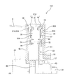
図1及び図2を用いて、第1実施形態に係る回転電機の概略構成について説明する。図1及び図2に示すように、本実施形態の回転電機10は、固定子30と、固定子30の内側に配置された回転子50とを備え、軸方向長さを短縮した扁平なインナーロータ型のモータである。この回転電機10は、後述の図11に示すように、例えば産業用ロボットの関節部7を駆動するモータ11等に使用される。
(1-1.回転電機の概略構成)
図1及び図2を用いて、第1実施形態に係る回転電機の概略構成について説明する。図1及び図2に示すように、本実施形態の回転電機10は、固定子30と、固定子30の内側に配置された回転子50とを備え、軸方向長さを短縮した扁平なインナーロータ型のモータである。この回転電機10は、後述の図11に示すように、例えば産業用ロボットの関節部7を駆動するモータ11等に使用される。
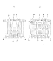
回転電機10はシャフト51を備えている。シャフト51は、回転電機10の軸方向一方側(図1中左側)に設けられた反負荷側ブラケット42(筐体の一例に相当)及び軸方向他方側(図1中右側)に設けられた負荷側ブラケット41(筐体の一例に相当)に、それぞれ反負荷側軸受44及び負荷側軸受43を介して回転自在に支持されている。シャフト51の反負荷側端部には、エンコーダ40が設けられている。なお、エンコーダ40は設置されなくてもよい。負荷側ブラケット41は、円筒状のフレーム部41aを一体に備えている。フレーム部41a、負荷側ブラケット41及び反負荷側ブラケット42は、回転電機10の筐体を構成する。
なお、本明細書において「負荷側」とは回転電機10に対してシャフト51が突出する方向(図1中右側)を指し、「反負荷側」とは負荷側の反対方向、すなわち回転電機10に対してエンコーダ40が配置される方向(図1中左側)を指す。
(1-2.回転子の構成)
回転子50は、固定子30と径方向に磁気的間隙を空けて、シャフト51の外周側に設けられている。回転子50は、周方向に配置された複数の永久磁石58と、永久磁石58の径方向外側及び径方向内側を挟むように配置された外側の回転子鉄心52及び内側の回転子鉄心53とを備える。複数の永久磁石58は、軸方向から見て実質的にV字状に配置された1対の永久磁石58が複数対(この例では16対)、周方向に沿うように配列されている。複数対の永久磁石58は、各対の永久磁石58の互いに向かい合う側の磁極同士が同極のN極又はS極となり、かつそのN極同士、S極同士の磁極が周方向に交互に繰り返されるように配置されている。永久磁石58、外側の回転子鉄心52、及び内側の回転子鉄心53は、ボルト57によってシャフト51に固定された円環状の大径の負荷側プレート55と、該第1プレート55の反負荷側に配置された狭幅の円環状の反負荷側プレート56との間に挟持される。そして、永久磁石58及び回転子鉄心52,53は、回転子鉄心52,53の各々を貫通して負荷側プレート55及び反負荷側プレート56を結合したボルト54によって一体に固定され、負荷側プレート55を介してシャフト51に支持されている。
回転子50は、固定子30と径方向に磁気的間隙を空けて、シャフト51の外周側に設けられている。回転子50は、周方向に配置された複数の永久磁石58と、永久磁石58の径方向外側及び径方向内側を挟むように配置された外側の回転子鉄心52及び内側の回転子鉄心53とを備える。複数の永久磁石58は、軸方向から見て実質的にV字状に配置された1対の永久磁石58が複数対(この例では16対)、周方向に沿うように配列されている。複数対の永久磁石58は、各対の永久磁石58の互いに向かい合う側の磁極同士が同極のN極又はS極となり、かつそのN極同士、S極同士の磁極が周方向に交互に繰り返されるように配置されている。永久磁石58、外側の回転子鉄心52、及び内側の回転子鉄心53は、ボルト57によってシャフト51に固定された円環状の大径の負荷側プレート55と、該第1プレート55の反負荷側に配置された狭幅の円環状の反負荷側プレート56との間に挟持される。そして、永久磁石58及び回転子鉄心52,53は、回転子鉄心52,53の各々を貫通して負荷側プレート55及び反負荷側プレート56を結合したボルト54によって一体に固定され、負荷側プレート55を介してシャフト51に支持されている。
(1-3.固定子の構成)
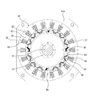
固定子30は、ヨーク部31から径方向内側に突出したティース部33を有するとともに、フレーム部41aの内周面に周方向に配置されて環状に連結された複数(この例では18個)の固定子鉄心32と、ティース部33に装着された複数(この例では18個)の空芯コイル20(固定子コイルの一例に相当)とを備えている。隣り合うティース部33,33間にはスロット34が形成され、ティース部33に装着された空芯コイル20は、周方向両側部がスロット34内に装着される。空芯コイル20の巻き始め側のリード端部21、巻き終り側のリード端部22は、空芯コイル20の反負荷側から径方向外側に引き出されて結線部39で結線され、外部の給電ケーブル8と接続される。
固定子30は、ヨーク部31から径方向内側に突出したティース部33を有するとともに、フレーム部41aの内周面に周方向に配置されて環状に連結された複数(この例では18個)の固定子鉄心32と、ティース部33に装着された複数(この例では18個)の空芯コイル20(固定子コイルの一例に相当)とを備えている。隣り合うティース部33,33間にはスロット34が形成され、ティース部33に装着された空芯コイル20は、周方向両側部がスロット34内に装着される。空芯コイル20の巻き始め側のリード端部21、巻き終り側のリード端部22は、空芯コイル20の反負荷側から径方向外側に引き出されて結線部39で結線され、外部の給電ケーブル8と接続される。
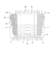
図3に示すように、ティース部33は、軸方向(図3中左右方向)中央の中央側ティース部33aと、中央側ティース部33aの軸方向両側に小さく突出した負荷側ティース部33b及び反負荷側ティース部33cとを有している。負荷側ティース部33b及び反負荷側ティース部33cは、周方向(図3中上下方向)の寸法が中央側ティース部33aよりも短くなっている。また、反負荷側ティース部33cは、負荷側ティース部33bよりも軸方向の寸法が長くなっている。空芯コイル20と負荷側ティース部33b、反負荷側ティース部33c、中央側ティース部33aとの間にはインシュレータ37が介挿されている。また、空芯コイル20の軸方向両側の端面23,24と、負荷側ブラケット41及び反負荷側ブラケット42との間には、図1に示すように、絶縁体36が密着して配置されている。絶縁体36としては、例えば絶縁シート等が用いられるが、空芯コイル20を被覆するモールド材や、ブラケットの表面に形成されたコーティング材でもよい。が設けられている。さらに、固定子鉄心32、空芯コイル20、及び絶縁体36を一体に樹脂成形したモールド樹脂部38が設けられている。
なお、図3において、符号18は、空芯コイル20の反負荷側の角部であり、符号19は、空芯コイル20の負荷側の角部である。本実施形態では、反負荷側の両側の角部18において、空芯コイル20の巻線17(後述の図5参照)の巻き位置の移動が行われる。負荷側の両側の角部19では、巻線17の巻き位置の移動は行われない。上述のように、反負荷側ティース部33cの軸方向寸法が負荷側ティース部33bよりも長いことにより、反負荷側の2つの角部18の曲率半径は負荷側の2つの角部19よりも大きくなる。
(1-4.空芯コイルの形状)
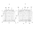
図4(b)に示すように、空芯コイル20は、径方向内側(図4(b)中右側)及び径方向外側(図4(b)中左側)に実質的に円筒形状の一部を構成する曲面状となる端面28及び端面29をそれぞれ備えている。また、空芯コイル20は、周方向両側(図4(b)中上側及び下側)に実質的に平面状となる端面25,25をそれぞれ備えている。また、空芯コイル20は、図4(c)に示すように、軸方向両側の負荷側、反負荷側に実質的に平面状となる端面23及び端面24をそれぞれ備えている。これら端面23及び端面24は、いずれも回転子50の回転軸心AX(図1参照)に垂直な面方向の端面となっている。
図4(b)に示すように、空芯コイル20は、径方向内側(図4(b)中右側)及び径方向外側(図4(b)中左側)に実質的に円筒形状の一部を構成する曲面状となる端面28及び端面29をそれぞれ備えている。また、空芯コイル20は、周方向両側(図4(b)中上側及び下側)に実質的に平面状となる端面25,25をそれぞれ備えている。また、空芯コイル20は、図4(c)に示すように、軸方向両側の負荷側、反負荷側に実質的に平面状となる端面23及び端面24をそれぞれ備えている。これら端面23及び端面24は、いずれも回転子50の回転軸心AX(図1参照)に垂直な面方向の端面となっている。
なお、上記の説明における「曲面状」及び「平面状」とは、厳密な意味での「曲面」及び「平面」ではない。すなわち、端面28,29については、曲面状のプレス治具により加圧成形された結果得られた「実質的に曲面状」の端面という意味であり、巻線17の輪郭による細かな凹凸形状や、コイル端面の形状によりプレス治具との間に隙間が生じた場合の窪み等の形状は許容される。端面23,24,25についても同様であり、平面状のプレス治具により加圧成形された結果得られた「実質的に平面状」の端面という意味であり、巻線17の輪郭による細かな凹凸形状や、コイル端面の形状によりプレス治具との間に隙間が生じた場合の窪み等の形状は許容される。
また、空芯コイル20は、周方向両側にスロット34内に装着されるスロット装着部26、及び、軸方向両側に固定子鉄心32の軸方向両側に位置するコイルエンド部27を備える。図4(b)に示すように、スロット装着部26の周方向の断面形状は、実質的に径方向外側ほど寸法が大きくなる扇形であり、図4(c)に示すように、コイルエンド部27の軸方向の断面形状は、実質的に長方形である。
以上のような空芯コイル20の形状により、複数(この例では18個)の空芯コイル20を固定子鉄心32に装着して周方向に配置したとき、1つの正確な円筒形状が形成され、空芯コイル20をブラケット41,42に密着させた固定子30を構成することができる。
(1-5.空芯コイルの巻線の構成)
図5に示すように、空芯コイル20を形成する巻線17は、周方向両側(図5中左右両側)と軸方向両側(図5中紙面の奥側及び手前側)の4つの平面部13において整列配置されている。巻線17の巻き位置の移動は、空芯コイル20の軸方向のいずれか一方側の2つの角部、本実施形態では反負荷側(図5中紙面の手前側)の両側の角部18のみで行われる。
図5に示すように、空芯コイル20を形成する巻線17は、周方向両側(図5中左右両側)と軸方向両側(図5中紙面の奥側及び手前側)の4つの平面部13において整列配置されている。巻線17の巻き位置の移動は、空芯コイル20の軸方向のいずれか一方側の2つの角部、本実施形態では反負荷側(図5中紙面の手前側)の両側の角部18のみで行われる。
なお、図5は、反負荷側のコイルエンド部27の側から見た加圧成形前の空芯コイル20の周方向の断面を示している。巻き始めのリード端部21は、巻き治具80の径方向外側より導入され、巻線17(「線材」ともいう。)の巻回が開始される。図5中右側の巻線17に示したX印は、図中右側のスロット装着部26に入って負荷側(図5中紙面の奥側)に向けて巻回される巻線17を示し、図5中左側の巻線17に示した番号は、負荷側に向けて巻回された巻線17が図中左側のスロット装着部26に入って反負荷側に向けて巻回される順序(内側から外側に巻く通常の巻き方式による巻回の順序)を示している。スロット装着部26と負荷側のコイルエンド部27の間は全て整列巻きであり、巻線17の巻き位置の移動は行われない。反負荷側のコイルエンド部27も整列巻きであるが、他の整列巻き部に対し径方向に半ピッチ位置がずれている。この半ピッチの位置ずれとなるように、反負荷側のコイルエンド部27の両側の角部18で巻き位置の移動が行われる。
このように巻線17の巻き位置の移動が反負荷側の角部18で行われる結果、周方向両側と軸方向両側の4つの平面部13において整列巻きが可能になり、反負荷側のコイルエンド部27を含めた空芯コイル20の外形部の6面全てにおける加圧成形が可能になる。なお、巻線17の巻き位置の移動を行う箇所は反負荷側の角部18のみに限定されるものではなく、4つの角部18,18,19,19のうちいずれか2つの角部において行われればよい。
図6(a)に空芯コイル20の巻線17の巻き始め時の様子を示し、図6(b)に空芯コイル20の巻線17の巻き終り時の様子を示す。なお、図6(a)は、巻線17の巻き始めより1層目の巻回を終え、2層目の巻回中の状態である。
図6(a)に示すように、巻き治具80に巻回される空芯コイル20の巻線17において、巻き始め側のリード端部21は、空芯コイル20の反負荷側(図6中紙面の手前側)の一方(図6(a)中右側)の角部18において径方向外側の第1層目より引き出される。一方、図6(b)に示すように、巻き終わり側のリード端部22は、空芯コイル20の反負荷側の他方(図6(b)中左側)の角部18においてコイル最外層より径方向外側に引き出される。
なお、例えば結線部39が固定子鉄心32の負荷側に配置される場合には、2つのリード端部21,22を負荷側の2つの角部19,19より引き出してもよい。また、例えば結線部39がコイルエンド部27の径方向内側に配置される場合には、2つのリード端部21,22をコイルエンド部27の径方向内側に向けて引き出してもよい。
(1-6.巻き治具の構成)
空芯コイル20は、巻線17を定位置に巻回できるような形状の巻き治具80に巻回された後、平坦な型に装着されて加圧成形される。図7(a)、図7(b)及び図7(c)に示すように、巻き治具80は、空芯コイル20の内側の巻き治具本体87と、巻き治具本体87の径方向両側(図7(a)中左右両側)にはめ合わされた径方向内側治具85及び径方向外側治具86とを備えている。この例では、図7(b)に示すように、巻き治具本体87は、負荷側治具81、反負荷側治具82、周方向右側治具83、及び周方向左側治具84の4つの組み合わせで構成されている。
空芯コイル20は、巻線17を定位置に巻回できるような形状の巻き治具80に巻回された後、平坦な型に装着されて加圧成形される。図7(a)、図7(b)及び図7(c)に示すように、巻き治具80は、空芯コイル20の内側の巻き治具本体87と、巻き治具本体87の径方向両側(図7(a)中左右両側)にはめ合わされた径方向内側治具85及び径方向外側治具86とを備えている。この例では、図7(b)に示すように、巻き治具本体87は、負荷側治具81、反負荷側治具82、周方向右側治具83、及び周方向左側治具84の4つの組み合わせで構成されている。
反負荷側治具82、周方向右側治具83、及び周方向左側治具84には、空芯コイル20の1層目の巻線17を導く溝88が形成されている。これにより、巻き治具80における巻線17の位置が固定される。反負荷側治具82の溝88は、他の溝付きの治具である周方向右側治具83、周方向左側治具84に対し半ピッチ、溝位置がずれている。
巻き治具本体87のうち、負荷側治具81には溝がないので、他の反負荷側治具82、周方向右側治具83、及び周方向左側治具84から取り外し可能である。このため、巻き治具80への空芯コイル20の巻線17の巻回後、初めに負荷側治具81が外される。次に、反負荷側治具82、周方向右側治具83、及び周方向左側治具84が取り外される。そして、巻回された空芯コイル20に平坦なコアピン71(後述の図8及び図9参照)が装着され、加圧成形される。
(1-7.空芯コイルの加圧成形)
上述のように、巻き治具80に巻線17を巻回して未成形の空芯コイル20を形成した後、空芯コイル20の径方向内側及び外側の端面を円筒形状の一部を構成する曲面状のプレス治具で加圧成形し、空芯コイル20の周方向両側及び軸方向両側の端面を平面状のプレス治具で加圧成形する。この空芯コイル20の加圧成形について図8及び図9を用いて説明する。
上述のように、巻き治具80に巻線17を巻回して未成形の空芯コイル20を形成した後、空芯コイル20の径方向内側及び外側の端面を円筒形状の一部を構成する曲面状のプレス治具で加圧成形し、空芯コイル20の周方向両側及び軸方向両側の端面を平面状のプレス治具で加圧成形する。この空芯コイル20の加圧成形について図8及び図9を用いて説明する。
図8に示すように、まず、巻線17の巻回により形成された未成形の空芯コイル20に、コアピン71が装着される。そして、コアピン71が上パンチ73に取り付けられ、上パンチ73を受容するダイ72の成形穴70にセットされる。
成形穴70は、空芯コイル20の軸方向両側に対応する前側及び後側が開口した有底の穴である。この成形穴70は、空芯コイル20の径方向内側の外形状を成形する径方向内側用の成形面70aと、空芯コイル20の周方向両側の外形状を成形する周方向用の1対の成形面70bを有する。成形面70aは、円筒形状の一部を構成する曲面状であり、具体的には、空芯コイル20の径方向内側の外形状に対応した所定の曲率で上に凸に湾曲した湾曲壁面からなる。1対の成形面70bは、平面状であり、具体的には、空芯コイル20の周方向両側の外形状に対応した傾斜で成形面70aの左右の辺から外開き状に立ち上がる傾斜壁面からなる。上パンチ73は、空芯コイル20の径方向外側の外形状を成形する成形面73aを有する。成形面73aは、円筒形状の一部を構成する曲面状であり、具体的には、空芯コイル20の径方向外側の外形状に対応した所定の曲率で上に凹に湾曲した湾曲壁面からなる。
空芯コイル20がダイ72の成形穴70にセットされたら、図8中白抜きの矢印に示すように、上パンチ73がダイ72に対し所定量降下される。これにより、ダイ72と上パンチ73とにより空芯コイル20の径方向両側の端面が押圧され、空芯コイル20の径方向両側の外形状が加圧成形される。また、空芯コイル20の周方向両側の端面が押圧され、空芯コイル20の周方向両側の外形状が加圧成形される。
次に、図9に示すように、上パンチ73とダイ72との間に形成された前後両側の1対の開口75のそれぞれに、横パンチ74が図9中白抜きの矢印で示すように挿入される。横パンチ74は、空芯コイル20の周方向断面形状に対応する左右方向の断面形状を有している。また、横パンチ74の空芯コイル20と接触する側の壁面は、平面状であり、具体的には、空芯コイル20の軸方向両側の端面に対応した扇型の外郭を有する垂直な成形面となっている。ダイ72の開口75に挿入されたそれぞれの横パンチ74が所定量前進されると、空芯コイル20の軸方向両側の端面が押圧され、空芯コイル20の軸方向両側の外形状が軸心AXに対して略垂直な端面となるように加圧成形される。
以上により、空芯コイル20の加圧成形が完了する。その後、成形された空芯コイル20を熱硬化性等の樹脂で樹脂モールドすることにより、本実施形態で使用する完成品の空芯コイル20が得られる。
なお、成形面73aを備えた上パンチ73及び成形面70aを備えたダイ72が曲面状のプレス治具の一例に相当し、1対の成形面70bを備えたダイ72及び横パンチ74が平面状のプレス治具の一例に相当する。
(1-8.加圧成形による巻線の変形)
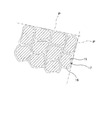
加圧成形後の空芯コイル20の各巻線17の断面の様子を図10に示す。巻線17は、導体15をエナメル等の絶縁被膜16で被覆した構造である。導体15は、例えば銅又はアルミ等からなる。なお、導体15にアルミを用いた場合には、空芯コイル20を軽量化でき、固定子30、ひいては回転電機10を軽量化できる。各巻線17は、加圧成形により丸形の断面が塑性変形した形状(例えば略矩形や略多角形等)となっている。図中の符号Pは、ダイ72の成形面70bや横パンチ74の成形面を表しており、加圧成形により空芯コイル20の端面が実質的に平面状に形成されている。これにより、占積率を高めつつ、各端面を所望の形状とした空芯コイル20を実現できる。
加圧成形後の空芯コイル20の各巻線17の断面の様子を図10に示す。巻線17は、導体15をエナメル等の絶縁被膜16で被覆した構造である。導体15は、例えば銅又はアルミ等からなる。なお、導体15にアルミを用いた場合には、空芯コイル20を軽量化でき、固定子30、ひいては回転電機10を軽量化できる。各巻線17は、加圧成形により丸形の断面が塑性変形した形状(例えば略矩形や略多角形等)となっている。図中の符号Pは、ダイ72の成形面70bや横パンチ74の成形面を表しており、加圧成形により空芯コイル20の端面が実質的に平面状に形成されている。これにより、占積率を高めつつ、各端面を所望の形状とした空芯コイル20を実現できる。
(1-9.扁平モータの用途)
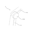
例えば産業用ロボットの関節部の駆動に使用するモータには、関節部の肥大化を防ぐためにモータを扁平形状に構成したい要望がある。図11に産業用ロボットの関節部の一例を示す。産業用ロボットの関節部7では、元アーム9と、先アーム12との間をモータ11で連結して、モータ11により関節部7を駆動し、元アーム9に対し先アーム12の回動動作を行わせている。
例えば産業用ロボットの関節部の駆動に使用するモータには、関節部の肥大化を防ぐためにモータを扁平形状に構成したい要望がある。図11に産業用ロボットの関節部の一例を示す。産業用ロボットの関節部7では、元アーム9と、先アーム12との間をモータ11で連結して、モータ11により関節部7を駆動し、元アーム9に対し先アーム12の回動動作を行わせている。
本実施形態の回転電機10は、軸方向に扁平なモータを構成することが可能であるので、産業用ロボットの関節部7等を駆動するモータ11として使用するのに好適である。
以上において、空芯コイル20における巻線17の巻き位置の移動を反負荷側の角部18のみで行い、周方向両側と軸方向両側の4つの平面部13において整列巻きとする構成、及び、リード端部21,22を角部18において引き出す構成が、径方向内側又は径方向外側への引き出しが、空芯コイルの径方向両側、軸方向両側、周方向両側の端面の加圧成形を可能とする手段の一例に相当する。
(1-10.第1実施形態の効果)
以上説明したように、第1実施形態の回転電機10は、ティース部33を備えた固定子鉄心32と、ティース部33に装着され、径方向内側及び外側に実質的に円筒形状の一部を構成する曲面状となる端面28,29を備えると共に周方向両側に実質的に平面状となる端面25,25及び軸方向両側に実質的に平面状となる端面23,24を備えた空芯コイル20と、を有する。
以上説明したように、第1実施形態の回転電機10は、ティース部33を備えた固定子鉄心32と、ティース部33に装着され、径方向内側及び外側に実質的に円筒形状の一部を構成する曲面状となる端面28,29を備えると共に周方向両側に実質的に平面状となる端面25,25及び軸方向両側に実質的に平面状となる端面23,24を備えた空芯コイル20と、を有する。
このように、空芯コイル20の軸方向両側に実質的に平面状となる端面23,24を備えるので、両端面23,24を負荷側ブラケット41及び反負荷側ブラケット42に十分に密着させることが可能となり、放熱性を向上できる。また、軸方向両側の端面23,24は加圧成形により平面状に形成されるので、軸方向両側のコイルエンド部27,27の軸方向長さを短縮できる。したがって、放熱性を損なうことなく軸方向長さを短縮した回転電機10を実現できる。
また、空芯コイル20の径方向内側及び外側に実質的に円筒形状の一部を構成する曲面状となる端面28,29を備えるので、複数の空芯コイル20を各ティース部33に装着したときに1つの正確な円筒形状が形成され、断面形状が単なる台形状であるコイルに比べて占積率を高めることができる。
また、本実施形態では特に、空芯コイル20の軸方向両側の端面23,24が回転子50の回転軸心AXに垂直な面方向の端面として形成される。これにより、例えばコイルエンド部27の軸方向の断面形状が径方向外側程寸法が大きくなる略扇形である場合に比べ、空芯コイル20の軸方向長さを短縮できる。その結果、軸方向長さの小さい扁平形の回転電機10を実現できる。
また、本実施形態では特に、空芯コイル20のスロット装着部26の周方向の断面形状が実質的に径方向外側ほど寸法が大きくなる扇形であり、コイルエンド部27の軸方向の断面形状が実質的に長方形である。これにより、占積率の高い固定子を構成できる。
また、本実施形態では特に、空芯コイル20は、スロット装着部26及びコイルエンド部27における各巻線17の断面形状が、丸形が加圧成形により塑性変形した形状を含むように構成される。これにより、占積率を高めつつ、各端面23,24,25,28,29を所望の形状とした空芯コイル20を実現できる。
また、本実施形態では特に、空芯コイル20は、周方向両側に位置する2つの平面部13(端面25,25を含む2つの平面部)及び軸方向両側に位置する2つの平面部13(端面23,24を含む2つの平面部)と、この4つの平面部13の各々の間に位置する4つの角部18,18,19,19と、を備え、各平面部13において巻線17が整列に配置され、4つの角部18,18,19,19のうちいずれか2つの角部において巻き位置の移動が行われるように、巻線17が巻回されて構成される。このように、巻線17の巻き位置の移動が角部のみで行われる結果、周方向両側と軸方向両側の4つの平面部13において整列巻きが可能となり、反負荷側のコイルエンド部27の端面24を含めた空芯コイル20の6面全てに対し加圧成形が可能となる。
また、本実施形態では特に、空芯コイル20は、巻線17の巻き位置の移動が行われる2つの角部18の曲率半径が、巻き位置の移動が行われない他の2つの角部19の曲率半径よりも大きくなるように構成される。これにより、巻線17の巻き位置の移動が行われる角部において、巻き位置の移動を無理なく行うのに必要な長さ(巻線17の経路の長さ)を確保できる。
また、本実施形態では特に、空芯コイル20は、反負荷側の2つの角部18,18よりコイルエンド部27の径方向外側に向けて引き出された2つのリード端部21,22を有する。これにより、2つのリード端部21,22をコイルエンド部27の径方向外側に配置された結線部39に導くことができる。また、2つのリード端部21,22を加圧成形が行われない角部より引き出すので、加圧成形によるリード端部の損傷を防止できる。
また、本実施形態では特に、巻き始め側のリード端部21は、反負荷側の一方の角部18において径方向外側の第1層目より引き出され、巻き終わり側のリード端部22は、反負荷側の他方の角部18においてコイル最外層より引き出される。これにより、巻線17を内側から外側に積層して巻回した通常の巻き方式の空芯コイル20を実現できる。
また、本実施形態では特に、空芯コイル20の軸方向両側の端面23,24と負荷側ブラケット41及び反負荷側ブラケット42との間に密着して配置された絶縁体36を有する。これにより、回転電機10の放熱性を損なうことなく、空芯コイル20と負荷側ブラケット41及び反負荷側ブラケット42との絶縁を確保できる。
また、本実施形態では特に、固定子鉄心32、空芯コイル20、及び絶縁体36を一体に成形したモールド樹脂部38を有する。これにより、固定子30が一体的に構成されるので、回転電機10の組立時の作業性を向上できる。また、固定子鉄心32と空芯コイル20とのガタつきを防止し、絶縁に対する長期的な信頼性を確保できる。
また、本実施形態では特に、空芯コイル20のコイルエンド部27の径方向外側に配置され、空芯コイル20のリード端部21,22を結線する結線部39を有する。このように、結線部39がコイルエンド部27の径方向外側に配置されるので、結線部39による回転電機10の軸方向長さの増大を防止できる。
<2.第2実施形態>
図12乃至図14を用いて、第2実施形態について説明する。
図12乃至図14を用いて、第2実施形態について説明する。
(2-1.回転電機の概略構成)
図12に、第2実施形態に係る回転電機10Aの概略構成を示す。回転電機10Aは、固定子30Aの構成が第1実施形態の回転電機10における固定子30と異なる。回転電機10Aのその他の構成は第1実施形態の回転電機10と同様である。図12において図10と同様な要素については同一の符号を付して適宜説明を省略又は簡略化する。
図12に、第2実施形態に係る回転電機10Aの概略構成を示す。回転電機10Aは、固定子30Aの構成が第1実施形態の回転電機10における固定子30と異なる。回転電機10Aのその他の構成は第1実施形態の回転電機10と同様である。図12において図10と同様な要素については同一の符号を付して適宜説明を省略又は簡略化する。
本実施形態における固定子30Aの固定子鉄心32Aは、ヨーク部31の軸方向両側に環状鉄心35を設けて、ヨーク部31及び両側の環状鉄心35からなるヨーク部31Aを有する。この構造により、ヨーク部31Aはティース部33より軸方向寸法が大きくなる。これにより、ティース部33の磁路の大きさを確保したままヨーク部31Aの内径を大きくすることができ、その分、ティース部33に装着する空芯コイル20Aのコイル寸法を大きく設計できる。
(2-2.空芯コイルの巻線の構成)
なお、空芯コイル20Aを、第1実施形態で説明した空芯コイル20のように、巻き始め側のリード端部21を第1層目のコイルエンド部27の径方向外側に引き出す構成とした場合、環状鉄心35に干渉する可能性があることから、環状鉄心35に干渉しないようなリード端部の設け方を工夫する必要がある。
なお、空芯コイル20Aを、第1実施形態で説明した空芯コイル20のように、巻き始め側のリード端部21を第1層目のコイルエンド部27の径方向外側に引き出す構成とした場合、環状鉄心35に干渉する可能性があることから、環状鉄心35に干渉しないようなリード端部の設け方を工夫する必要がある。
そこで、本実施形態では、図13に示すように、空芯コイル20Aの一方のリード端部21A(巻き終り側のリード端部に相当)は、径方向内側のコイル最外層より角部18を経て、コイルエンド部27の径方向外側に引き出され、もう一方のリード端部22A(巻き始め側のリード端部に相当)は、コイル最外層より角部18を経て、コイルエンド部27の外側に引き出されるように構成される。
すなわち、空芯コイル20Aの巻線17の巻回はいわゆるα巻き方式となっており、2本のリード端部21A,22Aが外側に形成される。なお、第1実施形態と同様に、巻線17の巻き位置の移動は、反負荷側の両側の角部18のみで行われ、周方向両側と軸方向両側の4つの平面部13において整列巻となり、反負荷側のコイルエンド部27を含めた空芯コイル20Aの外形6面全てで加圧成形される。
図13に示すように、巻線17の巻き始めは径方向内側より行われる。一方のリード端部22Aは巻き治具80Aの径方向外側へ1,2,3,・・・と15ターン巻回して1層目とし、これを2層目、3層目、・・・と巻回し、6層目の69ターン(符号22aで示す)で巻回を終了する。もう一方のリード端部21Aは径方向内側を2層目、3層目と巻回し、2ターン(符号21aで示す)で巻回を終了するため、空芯コイル20Aのターン数は第1実施形態の空芯コイル20と同じ71ターンである。
巻き治具80Aは、径方向外側治具86のリード端部21Aの位置が変更される以外は、第1実施形態で使用する巻き治具80と同じ形状である。
図14(a)に空芯コイル20Aの巻線17の巻き始め時の様子を示し、図14(b)に空芯コイル20Aの巻線17の巻き終り時の様子を示す。なお、図14(a)は、巻線17の巻き始めより1層目の巻回を終え、2層目の巻回中の状態である。
空芯コイル20Aの一方のリード端部21Aは、径方向内側のコイル最外層より反負荷側のコイルエンド部27の周方向右側の角部18を経て、コイルエンド部27の外側に引き出される。もう一方のリード端部22Aは、コイル最外層より反負荷側のコイルエンド部27の周方向左側の角部18を経て、コイルエンド部27の外側に引き出される。そのため、図12で示した環状鉄心35に干渉せずにリード端部21A,22Aを結線部39に導くことができる空芯コイル20Aが得られる。
(2-3.第2実施形態の効果)
以上説明した第2実施形態によれば、リード端部21A,22Aの両方を最外層より引き出した、いわゆるα巻き方式の空芯コイル20Aを実現できる。この場合、両方のリード端部21A,22Aをコイルエンド部27の軸方向外側位置で引き出すことができるので、固定子鉄心32Aのヨーク部31Aの軸方向寸法をティース部33よりも大きくした場合でも、リード端部21A,22Aとヨーク部31Aとの干渉を防止できる。
以上説明した第2実施形態によれば、リード端部21A,22Aの両方を最外層より引き出した、いわゆるα巻き方式の空芯コイル20Aを実現できる。この場合、両方のリード端部21A,22Aをコイルエンド部27の軸方向外側位置で引き出すことができるので、固定子鉄心32Aのヨーク部31Aの軸方向寸法をティース部33よりも大きくした場合でも、リード端部21A,22Aとヨーク部31Aとの干渉を防止できる。
また、本実施形態では特に、固定子30Aは、ティース部33及びティース部33よりも軸方向寸法が大きいヨーク部31Aを備えた固定子鉄心32Aを有する。これにより、ティース部33の磁路の大きさを確保しつつ、ヨーク部31Aの内径を大きくすることが可能となり、その分空芯コイル20Aの寸法を大きく設計できる。また、空芯コイル20Aの寸法を増大させない場合には、ヨーク部31Aの外径を小さくすることが可能となり、回転電機10Aの径方向寸法を小型化できる。
<3.変形例>
以上では、回転電機10,10Aがモータである場合を一例として説明したが、本実施形態は、回転電機10,10Aが発電機である場合にも適用することができる。
以上では、回転電機10,10Aがモータである場合を一例として説明したが、本実施形態は、回転電機10,10Aが発電機である場合にも適用することができる。
なお、以上の説明における「垂直」とは、厳密な意味での垂直ではない。すなわち、「垂直」とは、設計上、製造上の公差、誤差が許容され、「実質的に垂直」という意味である。
また、以上既に述べた以外にも、上記実施形態による手法を適宜組み合わせて利用しても良い。
その他、一々例示はしないが、上記実施形態は、その趣旨を逸脱しない範囲内において、種々の変更が加えられて実施されるものである。
10,10A 回転電機
13 平面部
17 巻線
18 角部
19 角部
20,20A 空芯コイル(固定子コイル)
21 リード端部
21A リード端部
22 リード端部
22A リード端部
23,24 端面
25 端面
26 スロット装着部
27 コイルエンド部
28 端面
29 端面
30,30A 固定子
31A ヨーク部
32,32A 固定子鉄心
33 ティース部
36 絶縁体
38 モールド樹脂部
39 結線部
41 負荷側ブラケット(筐体)
42 反負荷側ブラケット(筐体)
50 回転子
72 ダイ(プレス治具)
73 上パンチ(プレス治具)
74 横パンチ(プレス治具)
13 平面部
17 巻線
18 角部
19 角部
20,20A 空芯コイル(固定子コイル)
21 リード端部
21A リード端部
22 リード端部
22A リード端部
23,24 端面
25 端面
26 スロット装着部
27 コイルエンド部
28 端面
29 端面
30,30A 固定子
31A ヨーク部
32,32A 固定子鉄心
33 ティース部
36 絶縁体
38 モールド樹脂部
39 結線部
41 負荷側ブラケット(筐体)
42 反負荷側ブラケット(筐体)
50 回転子
72 ダイ(プレス治具)
73 上パンチ(プレス治具)
74 横パンチ(プレス治具)
Claims (14)
- 回転子及び固定子を有する回転電機であって、
ティース部を備えた固定子鉄心と、
前記ティース部に装着され、径方向内側及び外側に実質的に円筒形状の一部を構成する曲面状となる端面を備えると共に周方向両側及び軸方向両側に実質的に平面状となる端面を備えた空芯コイルと、
を有することを特徴とする回転電機。 - 前記空芯コイルは、
軸方向両側に前記回転子の回転軸心に垂直な面方向の前記端面を備える
ことを特徴とする請求項1に記載の回転電機。 - 前記空芯コイルは、
スロット装着部及びコイルエンド部を備え、
前記スロット装着部の周方向の断面形状が実質的に径方向外側ほど寸法が大きくなる扇形であり、前記コイルエンド部の軸方向の断面形状が実質的に長方形である
ことを特徴とする請求項1又は2に記載の回転電機。 - 前記空芯コイルは、
前記スロット装着部及び前記コイルエンド部における各巻線の断面形状が、丸形が加圧成形により塑性変形した形状を含むように構成される
ことを特徴とする請求項3に記載の回転電機。 - 前記空芯コイルは、
周方向両側及び軸方向両側に位置する4つの平面部と、
前記平面部の各々の間に位置する4つの角部と、を備え、
前記平面部において巻線が整列に配置され、前記4つの角部のうちいずれか2つの角部において巻き位置の移動が行われるように、前記巻線が巻回されて構成される
ことを特徴とする請求項1乃至4のいずれか1項に記載の回転電機。 - 前記空芯コイルは、
前記巻線の巻き位置の移動が行われる前記2つの角部の曲率半径が、前記巻線の巻き位置の移動が行われない他の2つの角部の曲率半径よりも大きくなるように構成される
ことを特徴とする請求項5に記載の回転電機。 - 前記空芯コイルは、
軸方向一方側の2つの前記角部又は軸方向他方側の2つの前記角部よりコイルエンド部の径方向外側又は内側に向けて引き出された2つのリード端部を有する
ことを特徴とする請求項5又は6に記載の回転電機。 - 巻き始め側の前記リード端部は、
軸方向一方側の一方の角部において径方向外側の第1層目より引き出され、
巻き終わり側の前記リード端部は、
軸方向一方側の他方の角部においてコイル最外層より引き出される
ことを特徴とする請求項7に記載の回転電機。 - 巻き始め側の前記リード端部は、
軸方向一方側の一方の角部において径方向内側のコイル最外層より引き出され、
巻き終わり側の前記リード端部は、
軸方向一方側の他方の角部においてコイル最外層より引き出される
ことを特徴とする請求項7に記載の回転電機。 - 前記空芯コイルの軸方向両側の前記端面と筐体との間に密着して配置された絶縁体をさらに有する
ことを特徴とする請求項1乃至9のいずれか1項に記載の回転電機。 - 固定子鉄心、前記空芯コイル、及び前記絶縁体を一体に成形したモールド樹脂部をさらに有する
ことを特徴とする請求項10に記載の回転電機。 - 前記空芯コイルのコイルエンド部の径方向外側又は内側に配置され、前記空芯コイルのリード端部を結線する結線部をさらに有する
ことを特徴とする請求項1乃至11のいずれか1項に記載の回転電機。 - 前記固定子は、
ティース部及び前記ティース部よりも軸方向寸法が大きいヨーク部を備えた固定子鉄心を有する
ことを特徴とする請求項1乃至12のいずれか1項に記載の回転電機。 - 回転子及び固定子を有する回転電機の製造方法であって、
固定子コイルの線材を巻き治具に巻回することと、
巻回により形成された空芯コイルの径方向内側及び外側の端面を円筒形状の一部を構成する曲面状のプレス治具で加圧成形することと、
前記空芯コイルの周方向両側及び軸方向両側の端面を平面状のプレス治具で加圧成形することと、
を有することを特徴とする回転電機の製造方法。
Priority Applications (3)
| Application Number | Priority Date | Filing Date | Title |
|---|---|---|---|
| JP2016508404A JP6372562B2 (ja) | 2014-03-19 | 2014-03-19 | 回転電機 |
| PCT/JP2014/057604 WO2015140970A1 (ja) | 2014-03-19 | 2014-03-19 | 回転電機及び回転電機の製造方法 |
| US15/247,929 US10547219B2 (en) | 2014-03-19 | 2016-08-26 | Rotating electric machine having air core coil with curved end surfaces |
Applications Claiming Priority (1)
| Application Number | Priority Date | Filing Date | Title |
|---|---|---|---|
| PCT/JP2014/057604 WO2015140970A1 (ja) | 2014-03-19 | 2014-03-19 | 回転電機及び回転電機の製造方法 |
Related Child Applications (1)
| Application Number | Title | Priority Date | Filing Date |
|---|---|---|---|
| US15/247,929 Continuation US10547219B2 (en) | 2014-03-19 | 2016-08-26 | Rotating electric machine having air core coil with curved end surfaces |
Publications (1)
| Publication Number | Publication Date |
|---|---|
| WO2015140970A1 true WO2015140970A1 (ja) | 2015-09-24 |
Family
ID=54143975
Family Applications (1)
| Application Number | Title | Priority Date | Filing Date |
|---|---|---|---|
| PCT/JP2014/057604 Ceased WO2015140970A1 (ja) | 2014-03-19 | 2014-03-19 | 回転電機及び回転電機の製造方法 |
Country Status (3)
| Country | Link |
|---|---|
| US (1) | US10547219B2 (ja) |
| JP (1) | JP6372562B2 (ja) |
| WO (1) | WO2015140970A1 (ja) |
Cited By (7)
| Publication number | Priority date | Publication date | Assignee | Title |
|---|---|---|---|---|
| WO2017130309A1 (ja) * | 2016-01-27 | 2017-08-03 | 三菱電機株式会社 | 着磁方法、回転子、電動機およびスクロール圧縮機 |
| WO2020137039A1 (ja) * | 2018-12-28 | 2020-07-02 | 株式会社マキタ | 電動工具用の分布巻きモータ、電動工具及び芝刈り機 |
| US11336132B2 (en) | 2020-09-21 | 2022-05-17 | Evr Motors Ltd | Electric machine with liquid cooled coils and stator core |
| US12046949B1 (en) | 2023-12-28 | 2024-07-23 | Evr Motors Ltd | Electric machine with coils bridged with toothed clips |
| US12081073B2 (en) | 2021-10-04 | 2024-09-03 | Evr Motors Ltd | Electric machine with multi-tapered yokes |
| US12136869B1 (en) | 2023-12-28 | 2024-11-05 | Evr Motors Ltd | Heat dissipation plate for electric machine |
| US12278519B1 (en) | 2023-12-28 | 2025-04-15 | Evr Motors Ltd | Electric machine with multiple toothed spacers in coils |
Families Citing this family (4)
| Publication number | Priority date | Publication date | Assignee | Title |
|---|---|---|---|---|
| US10110080B2 (en) * | 2015-11-30 | 2018-10-23 | Caterpillar Inc. | Coil and stator assembly of a rotary electric machine |
| US11482913B2 (en) * | 2017-09-28 | 2022-10-25 | Nidec Corporation | Coil manufacturing method, coil manufacturing device, coil, and motor |
| CN110211802B (zh) * | 2019-06-21 | 2024-02-09 | 中山市三乐电子有限公司 | 线圈绕线机 |
| CN112865459B (zh) * | 2021-04-12 | 2023-09-01 | 北京航空航天大学 | 具有弓形永磁体的空心杯结构电机 |
Citations (2)
| Publication number | Priority date | Publication date | Assignee | Title |
|---|---|---|---|---|
| JP2004254421A (ja) * | 2003-02-20 | 2004-09-09 | Daikin Ind Ltd | 電動機およびその製造方法 |
| WO2014030359A1 (ja) * | 2012-08-21 | 2014-02-27 | 株式会社安川電機 | コイル、回転電機、及びコイルの製造方法 |
Family Cites Families (25)
| Publication number | Priority date | Publication date | Assignee | Title |
|---|---|---|---|---|
| US6870292B2 (en) * | 2001-11-28 | 2005-03-22 | Nissan Motor Co., Ltd. | Stator for motor |
| JP4214383B2 (ja) * | 2003-02-14 | 2009-01-28 | 株式会社安川電機 | 固定子ピースおよびモータの固定子 |
| JP4367030B2 (ja) * | 2003-07-03 | 2009-11-18 | パナソニック株式会社 | 電動機およびその電動機の製造方法 |
| JP2006087244A (ja) * | 2004-09-16 | 2006-03-30 | Asmo Co Ltd | 回転電機 |
| JP4281733B2 (ja) * | 2005-11-21 | 2009-06-17 | トヨタ自動車株式会社 | 電気モータの分割ステータ |
| JP2008178199A (ja) * | 2007-01-17 | 2008-07-31 | Toyota Motor Corp | コイル製造方法、モータのコイル、及びモータの固定子 |
| WO2008149649A1 (ja) | 2007-06-06 | 2008-12-11 | Kabushiki Kaisha Yaskawa Denki | 回転電機およびその製造方法 |
| JP4340740B2 (ja) * | 2007-07-19 | 2009-10-07 | トヨタ自動車株式会社 | 電動機のステータに用いられる接続線、その接続線を備えたステータおよびその接続線の曲げ方法 |
| JP2009050116A (ja) * | 2007-08-22 | 2009-03-05 | Panasonic Corp | コンデンサ電動機とその製造方法 |
| US8063547B2 (en) * | 2008-07-28 | 2011-11-22 | Kabushiki Kaisha Yaskawa Denki | Rotating electric machine and manufacturing method thereof |
| US10038349B2 (en) * | 2008-08-15 | 2018-07-31 | Millennial Research Corporation | Multi-phase modular coil element for electric motor and generator |
| JP2010251287A (ja) * | 2009-03-23 | 2010-11-04 | Autonetworks Technologies Ltd | 端子金具付き電線の製造方法 |
| JP5740930B2 (ja) | 2010-03-03 | 2015-07-01 | 日本電産株式会社 | ステータ及びモータ |
| JP5740931B2 (ja) | 2010-03-03 | 2015-07-01 | 日本電産株式会社 | 分割ステータ、及びモータ |
| EP2525475A4 (en) * | 2010-05-26 | 2016-10-12 | Toyota Motor Co Ltd | STATOR CONSTRUCTION AND METHOD FOR PRODUCING A STATOR |
| JP5282780B2 (ja) * | 2010-12-09 | 2013-09-04 | 株式会社安川電機 | 回転電機 |
| US20140035428A1 (en) * | 2011-02-25 | 2014-02-06 | Mitsubishi Electric Corporation | Stator of rotary electric machine, and manufacturing method therefor |
| WO2012178102A2 (en) * | 2011-06-24 | 2012-12-27 | The Regents Of The Unversity Of Colorado, A Body Corporate | Compositions, methods and uses for alpha-1 antitrypsin fusion molecules |
| DE102011083128A1 (de) * | 2011-09-21 | 2013-03-21 | Matuschek Meßtechnik GmbH | Elektromotor |
| JP5741534B2 (ja) * | 2012-08-03 | 2015-07-01 | トヨタ自動車株式会社 | 集中巻コイル |
| JP5928602B2 (ja) * | 2012-09-28 | 2016-06-01 | 株式会社安川電機 | コイル、回転電機、及びリニアモータ |
| CN104737422B (zh) * | 2012-10-16 | 2017-05-24 | 三菱电机株式会社 | 旋转电机的电枢 |
| US20150001984A1 (en) * | 2013-06-28 | 2015-01-01 | Remy Technologies, Llc | In-slot stator winding compaction |
| CN106233593B (zh) * | 2014-06-20 | 2019-01-15 | 三菱电机株式会社 | 旋转电机的制造方法 |
| JP6369293B2 (ja) * | 2014-11-06 | 2018-08-08 | 株式会社デンソー | 回転電機の固定子 |
-
2014
- 2014-03-19 WO PCT/JP2014/057604 patent/WO2015140970A1/ja not_active Ceased
- 2014-03-19 JP JP2016508404A patent/JP6372562B2/ja active Active
-
2016
- 2016-08-26 US US15/247,929 patent/US10547219B2/en active Active
Patent Citations (3)
| Publication number | Priority date | Publication date | Assignee | Title |
|---|---|---|---|---|
| JP2004254421A (ja) * | 2003-02-20 | 2004-09-09 | Daikin Ind Ltd | 電動機およびその製造方法 |
| WO2014030359A1 (ja) * | 2012-08-21 | 2014-02-27 | 株式会社安川電機 | コイル、回転電機、及びコイルの製造方法 |
| WO2014030214A1 (ja) * | 2012-08-21 | 2014-02-27 | 株式会社安川電機 | コイル、回転電機、及びコイルの製造方法 |
Cited By (15)
| Publication number | Priority date | Publication date | Assignee | Title |
|---|---|---|---|---|
| GB2562859B (en) * | 2016-01-27 | 2022-07-06 | Mitsubishi Electric Corp | Magnetizing method, rotor, motor, and scroll compressor |
| JPWO2017130309A1 (ja) * | 2016-01-27 | 2018-04-26 | 三菱電機株式会社 | 着磁方法、回転子、電動機およびスクロール圧縮機 |
| GB2562859A (en) * | 2016-01-27 | 2018-11-28 | Mitsubishi Electric Corp | Magnetizing method, rotor, electric motor, and scroll compressor |
| WO2017130309A1 (ja) * | 2016-01-27 | 2017-08-03 | 三菱電機株式会社 | 着磁方法、回転子、電動機およびスクロール圧縮機 |
| WO2020137039A1 (ja) * | 2018-12-28 | 2020-07-02 | 株式会社マキタ | 電動工具用の分布巻きモータ、電動工具及び芝刈り機 |
| US11349359B2 (en) | 2020-09-21 | 2022-05-31 | Evr Motors Ltd | Electric machine with SMC rotor core sandwiched between bandage and magnets |
| US11336132B2 (en) | 2020-09-21 | 2022-05-17 | Evr Motors Ltd | Electric machine with liquid cooled coils and stator core |
| US11451099B2 (en) | 2020-09-21 | 2022-09-20 | Evr Motors Ltd | Method of inserting multi-part tooth of an electric machine into a coil |
| US11489379B2 (en) | 2020-09-21 | 2022-11-01 | Evr Motors Ltd | Electric machine with SMC stator core |
| US11594920B2 (en) | 2020-09-21 | 2023-02-28 | Evr Motors Ltd | Electric machine with liquid-cooled stator core |
| US11831202B2 (en) | 2020-09-21 | 2023-11-28 | Evr Motors Ltd | Electric machine with multi-part trapezoidal teeth |
| US12081073B2 (en) | 2021-10-04 | 2024-09-03 | Evr Motors Ltd | Electric machine with multi-tapered yokes |
| US12046949B1 (en) | 2023-12-28 | 2024-07-23 | Evr Motors Ltd | Electric machine with coils bridged with toothed clips |
| US12136869B1 (en) | 2023-12-28 | 2024-11-05 | Evr Motors Ltd | Heat dissipation plate for electric machine |
| US12278519B1 (en) | 2023-12-28 | 2025-04-15 | Evr Motors Ltd | Electric machine with multiple toothed spacers in coils |
Also Published As
| Publication number | Publication date |
|---|---|
| JPWO2015140970A1 (ja) | 2017-04-06 |
| US20160365758A1 (en) | 2016-12-15 |
| US10547219B2 (en) | 2020-01-28 |
| JP6372562B2 (ja) | 2018-08-15 |
Similar Documents
| Publication | Publication Date | Title |
|---|---|---|
| JP6372562B2 (ja) | 回転電機 | |
| JP5537964B2 (ja) | 回転電機 | |
| JP6298161B2 (ja) | 固定子コイル、固定子、電磁装置、ならびに、固定子コイルの製造方法 | |
| JPWO2020017133A1 (ja) | 分布巻ラジアルギャップ型回転電機及びその固定子 | |
| JP5365476B2 (ja) | 回転電機 | |
| JP5928602B2 (ja) | コイル、回転電機、及びリニアモータ | |
| JP6331219B2 (ja) | 可動電機、コイルの製造方法 | |
| CN106067701A (zh) | 旋转电机及其制造方法、定子线圈、线圈树脂结构体 | |
| JP2018061341A (ja) | アキシャルギャップ型モータ | |
| JP2009100489A (ja) | スロットレス形回転電機 | |
| WO2018180720A1 (ja) | 電動モータおよびその製造方法 | |
| WO2018043364A1 (ja) | 巻線固定構造体、及び電動機 | |
| CN102983685A (zh) | 旋转电机的制造方法和旋转电机 | |
| CN106411014B (zh) | 旋转电机及其制造方法、定子线圈、线圈树脂结构体 | |
| JP7254140B1 (ja) | 回転電機 | |
| CN103683555A (zh) | 定子和旋转电机 | |
| JP6660606B2 (ja) | 回転電機、回転電機の製造方法 | |
| CN210577969U (zh) | 定子芯片及旋转电机 | |
| JP6428684B2 (ja) | 回転電機 | |
| JP5910363B2 (ja) | 回転電機の固定子 | |
| WO2011114758A1 (ja) | ステータおよび回転電機 | |
| JP5271991B2 (ja) | 回転電機の固定子 | |
| JP2017208973A (ja) | コアレスモータ | |
| WO2022208750A1 (ja) | モーター構造 | |
| JP2005095000A (ja) | 内転型電動機の固定子 |
Legal Events
| Date | Code | Title | Description |
|---|---|---|---|
| 121 | Ep: the epo has been informed by wipo that ep was designated in this application |
Ref document number: 14886164 Country of ref document: EP Kind code of ref document: A1 |
|
| ENP | Entry into the national phase |
Ref document number: 2016508404 Country of ref document: JP Kind code of ref document: A |
|
| NENP | Non-entry into the national phase |
Ref country code: DE |
|
| 122 | Ep: pct application non-entry in european phase |
Ref document number: 14886164 Country of ref document: EP Kind code of ref document: A1 |