WO2015137182A1 - 姿勢変換装置、整列装置及び姿勢変換方法、整列方法 - Google Patents
姿勢変換装置、整列装置及び姿勢変換方法、整列方法 Download PDFInfo
- Publication number
- WO2015137182A1 WO2015137182A1 PCT/JP2015/056128 JP2015056128W WO2015137182A1 WO 2015137182 A1 WO2015137182 A1 WO 2015137182A1 JP 2015056128 W JP2015056128 W JP 2015056128W WO 2015137182 A1 WO2015137182 A1 WO 2015137182A1
- Authority
- WO
- WIPO (PCT)
- Prior art keywords
- component
- cavity
- posture
- contact
- reference surface
- Prior art date
- Legal status (The legal status is an assumption and is not a legal conclusion. Google has not performed a legal analysis and makes no representation as to the accuracy of the status listed.)
- Ceased
Links
Images






Classifications
-
- B—PERFORMING OPERATIONS; TRANSPORTING
- B65—CONVEYING; PACKING; STORING; HANDLING THIN OR FILAMENTARY MATERIAL
- B65G—TRANSPORT OR STORAGE DEVICES, e.g. CONVEYORS FOR LOADING OR TIPPING, SHOP CONVEYOR SYSTEMS OR PNEUMATIC TUBE CONVEYORS
- B65G47/00—Article or material-handling devices associated with conveyors; Methods employing such devices
- B65G47/74—Feeding, transfer, or discharging devices of particular kinds or types
- B65G47/84—Star-shaped wheels or devices having endless travelling belts or chains, the wheels or devices being equipped with article-engaging elements
- B65G47/846—Star-shaped wheels or wheels equipped with article-engaging elements
- B65G47/848—Star-shaped wheels or wheels equipped with article-engaging elements the article-engaging elements being suction or magnetic means
-
- B—PERFORMING OPERATIONS; TRANSPORTING
- B65—CONVEYING; PACKING; STORING; HANDLING THIN OR FILAMENTARY MATERIAL
- B65G—TRANSPORT OR STORAGE DEVICES, e.g. CONVEYORS FOR LOADING OR TIPPING, SHOP CONVEYOR SYSTEMS OR PNEUMATIC TUBE CONVEYORS
- B65G47/00—Article or material-handling devices associated with conveyors; Methods employing such devices
- B65G47/22—Devices influencing the relative position or the attitude of articles during transit by conveyors
- B65G47/24—Devices influencing the relative position or the attitude of articles during transit by conveyors orientating the articles
- B65G47/248—Devices influencing the relative position or the attitude of articles during transit by conveyors orientating the articles by turning over or inverting them
-
- B—PERFORMING OPERATIONS; TRANSPORTING
- B65—CONVEYING; PACKING; STORING; HANDLING THIN OR FILAMENTARY MATERIAL
- B65G—TRANSPORT OR STORAGE DEVICES, e.g. CONVEYORS FOR LOADING OR TIPPING, SHOP CONVEYOR SYSTEMS OR PNEUMATIC TUBE CONVEYORS
- B65G47/00—Article or material-handling devices associated with conveyors; Methods employing such devices
- B65G47/74—Feeding, transfer, or discharging devices of particular kinds or types
- B65G47/76—Fixed or adjustable ploughs or transverse scrapers
- B65G47/763—Fixed ploughs or transverse scrapers
-
- B—PERFORMING OPERATIONS; TRANSPORTING
- B65—CONVEYING; PACKING; STORING; HANDLING THIN OR FILAMENTARY MATERIAL
- B65G—TRANSPORT OR STORAGE DEVICES, e.g. CONVEYORS FOR LOADING OR TIPPING, SHOP CONVEYOR SYSTEMS OR PNEUMATIC TUBE CONVEYORS
- B65G47/00—Article or material-handling devices associated with conveyors; Methods employing such devices
- B65G47/74—Feeding, transfer, or discharging devices of particular kinds or types
- B65G47/84—Star-shaped wheels or devices having endless travelling belts or chains, the wheels or devices being equipped with article-engaging elements
- B65G47/846—Star-shaped wheels or wheels equipped with article-engaging elements
-
- H—ELECTRICITY
- H05—ELECTRIC TECHNIQUES NOT OTHERWISE PROVIDED FOR
- H05K—PRINTED CIRCUITS; CASINGS OR CONSTRUCTIONAL DETAILS OF ELECTRIC APPARATUS; MANUFACTURE OF ASSEMBLAGES OF ELECTRICAL COMPONENTS
- H05K13/00—Apparatus or processes specially adapted for manufacturing or adjusting assemblages of electric components
- H05K13/02—Feeding of components
- H05K13/022—Feeding of components with orientation of the elements
-
- B—PERFORMING OPERATIONS; TRANSPORTING
- B65—CONVEYING; PACKING; STORING; HANDLING THIN OR FILAMENTARY MATERIAL
- B65G—TRANSPORT OR STORAGE DEVICES, e.g. CONVEYORS FOR LOADING OR TIPPING, SHOP CONVEYOR SYSTEMS OR PNEUMATIC TUBE CONVEYORS
- B65G2201/00—Indexing codes relating to handling devices, e.g. conveyors, characterised by the type of product or load being conveyed or handled
- B65G2201/02—Articles
-
- B—PERFORMING OPERATIONS; TRANSPORTING
- B65—CONVEYING; PACKING; STORING; HANDLING THIN OR FILAMENTARY MATERIAL
- B65G—TRANSPORT OR STORAGE DEVICES, e.g. CONVEYORS FOR LOADING OR TIPPING, SHOP CONVEYOR SYSTEMS OR PNEUMATIC TUBE CONVEYORS
- B65G2811/00—Indexing codes relating to common features for more than one conveyor kind or type
- B65G2811/06—Devices controlling the relative position of articles
- B65G2811/0621—Devices controlling the relative position of articles by modifying the orientation or position of articles
- B65G2811/0626—Orientation of articles
-
- B—PERFORMING OPERATIONS; TRANSPORTING
- B65—CONVEYING; PACKING; STORING; HANDLING THIN OR FILAMENTARY MATERIAL
- B65G—TRANSPORT OR STORAGE DEVICES, e.g. CONVEYORS FOR LOADING OR TIPPING, SHOP CONVEYOR SYSTEMS OR PNEUMATIC TUBE CONVEYORS
- B65G2811/00—Indexing codes relating to common features for more than one conveyor kind or type
- B65G2811/06—Devices controlling the relative position of articles
- B65G2811/0647—Changing the direction of movement of articles or bulk material
- B65G2811/0652—Accessories
Definitions
- the present invention relates to a posture conversion device, an alignment device, a posture conversion method, and an alignment method, and more particularly to a technique for changing the posture of a rectangular parallelepiped component.
- the chip component P in a sideways posture is placed in a cavity 104 cut out along the outer periphery of the rotor 101.
- the rotor 101 is rotated with respect to the base 103 while being sucked and held.
- a guide surface 111 is formed on the base 103, and the chip component P is lifted by the guide surface 111 with the rotation of the rotor 101 to bring the chip component P into an upright posture.
- the chip component P in the standing posture is sucked and held in the cavity 104 cut out along the outer periphery of the rotor 101.
- the biasing member 120 is disposed on the rotor 101. As the rotor 101 rotates, the abutting surface 121 of the urging member 120 is brought into contact with the upper part of the chip part P, and the upper part of the chip part P is urged by the abutting surface 121, so that the chip part P is placed sideways.
- Patent Document 1 For example, refer to Patent Document 1.
- the posture of the chip component When converting the former sideways posture to the standing posture, the posture of the chip component can be reliably changed.
- the present invention is intended to provide a posture conversion device, an alignment device, a posture conversion method, and an alignment method that can reliably change the posture of a component.
- the present invention provides a posture changing device configured as follows.
- the posture changing device is used for a rectangular parallelepiped component having a pair of opposing end faces having a rectangular shape and four side faces connecting the end faces.
- the posture changing device includes a base, a conveying member, and an urging member.
- the base includes a reference surface and an engagement groove formed in a groove shape with respect to the reference surface.
- the engagement groove includes an inclined surface that is inclined with respect to a direction orthogonal to a direction connecting one end to the other end of the engagement groove. The slope is formed so that the end face of the component can contact in a section from the one end to a predetermined position between the one end and the other end.
- the conveying member includes first and second main surfaces facing each other, and a cavity penetrating between the first and second main surfaces.
- the transport member moves relative to the base so that the second main surface faces the reference surface and the cavity sequentially faces the one end to the other end of the engagement groove.
- the cavity moves after the component is accommodated in the cavity so that the end surface of the component is in contact with the reference surface, and the side surface of the component is in contact with the reference surface
- a part of the component that is in contact with the inclined surface at the predetermined position protrudes from the first main surface.
- the urging member abuts on a part of the component protruding from the first main surface at the predetermined position, and urges the component with relative movement of the conveying member with respect to the base.
- the component is rotated around a corner or a round corner of the component on the valley side of the slope so that the end face of the component is separated from the slope.
- the component housed in the cavity is conveyed along the engagement groove along with the relative movement of the conveyance member with respect to the base, so that the end surface of the component contacts the reference surface.
- the posture is converted into a posture in which the side surface is in contact with the reference surface.
- the apparatus further includes suction means for sucking the parts housed in the cavity.
- the suction means is provided on the second main surface side of the transport member, and sucks the component in a direction opposite to a direction in which the component is urged by the contact member.
- the conveying member is formed with a suction hole that communicates with the cavity and is connected to a decompression source and sucks the component accommodated in the cavity in a direction opposite to the bottom line with respect to the inclined surface.
- the components housed in the cavities can be attracted to prevent the components from being displaced, and the posture change of the components can be stabilized. Since it is possible to prevent the component from falling off or being displaced from the cavity, the direction of the reference plane can be arbitrarily selected. In addition, even if the biasing member is tilted to some extent by the biasing member and then the biasing member is urged, the component can be further tilted by suction from the suction hole.
- the present invention provides an alignment apparatus including the posture changing device having the above-described configuration and a component supply unit that supplies the component to the cavity.
- the component supply unit supplies the component to the cavity so that an end surface of the component is in contact with the reference surface and a side surface of the component is in contact with the reference surface.
- the component supplied to the cavity so that the end surface is in contact with the reference surface is transported along the engagement groove along with the relative movement of the transport member with respect to the base, and by the biasing member.
- the side surface is converted into a posture in contact with the reference surface.
- the component supplied to the cavity so that the side surface abuts on the reference surface is transported along with the relative movement of the transport member with respect to the base, but without being biased by the biasing member, The side surface remains in contact with the reference surface.
- the present invention provides a posture changing method configured as follows in order to solve the above-described problems.
- the posture changing method is used for a rectangular parallelepiped component having a pair of opposing end faces having a rectangular shape and four side faces connecting the end faces.
- a first component housing the component in the cavity of a conveying member having first and second main surfaces facing each other and a cavity penetrating between the first and second main surfaces.
- the transport member is moved relative to the base having a reference surface and an engagement groove formed in a groove shape with respect to the reference surface, and is accommodated in the cavity.
- the end surface of the component whose end surface is in contact with the reference surface is defined as the one end of the engagement groove.
- the urging member is brought into contact, and with the relative movement and relative movement of the conveying member with respect to the base, the part of the part is urged, and the corner of the part on the valley side of the slope of the engagement groove or Rotate the part around a rounded corner, A surface away from the inclined surface, it includes a second sub-step of further tilting the component, a. After the second step, the posture of the component is converted into a posture in which the side surface is in contact with the reference surface.
- the part housed in the cavity and having the end face in contact with the reference plane passes through the engagement groove, so that the center line connecting the end faces is perpendicular to the reference plane, and the center line is the reference plane. Converted to a parallel posture.
- the component housed in the cavity is sucked in a direction opposite to a direction in which the component is urged by the contact member.
- the components housed in the cavities can be attracted to prevent the components from being displaced, and the posture change of the components can be stabilized. Since it is possible to prevent the component from falling off or being displaced from the cavity, the direction of the reference plane can be arbitrarily selected. In addition, even if the biasing member is tilted to some extent by the biasing member and then the biasing member is urged, the component can be further tilted by suction.
- the present invention also provides an alignment method. That is, in the first step, the component is supplied to the cavity so that the end surface of the component is in contact with the reference surface and the side surface of the component is in contact with the reference surface.
- the component supplied to the cavity so that the end surface abuts on the reference surface in the first step is in a posture in which the side surface abuts on the reference surface after the second step.
- the component supplied to the cavity so that the side surface abuts on the reference surface in the first step is in a posture in which the side surface abuts on the reference surface after the second step.
- the present invention it is possible to suppress the variation in the position of the rotation fulcrum when converting the posture of the component, and to reliably convert the posture of the component.
- (Modification 3) It is a schematic diagram showing a schematic structure of an endless belt.
- (Modification 4) 1 is a schematic diagram showing a schematic configuration of a rotating drum.
- (Modification 5) It is explanatory drawing of the operation
- (Conventional example 1) It is explanatory drawing of the operation
- FIG. 1 is a perspective view showing a main part of the configuration of the posture changing device.
- FIG. 2 is a plan view of a principal part showing the configuration of the posture changing device.
- the attitude changing device includes a base 14 having a reference surface 14a, a rotor 10 as a conveying member, a biasing member 20, and a component supply unit (not shown). 2 postures are converted.
- the posture changing device can be used for applications such as characteristic selection of parts 2, appearance selection, external electrode processing, and lead attachment.
- the part 2 has a rectangular parallelepiped shape, and has end faces 2s, 2t facing each other in a rectangular shape and four side faces 2m, 2n, 2u, 2v connecting the end faces 2s, 2t.
- the component 2 is an electronic component such as a multilayer ceramic capacitor, a thermistor, or a coil, and the length between the end surfaces 2s and 2t of the component 2 is L, and between the pair of side surfaces 2u and 2v of the component 2 facing each other. If the length is W and the length between the other pair of side surfaces 2m, 2n of the component 2 facing each other is T, L> W, L> T, W and T are 0.05 to 5 mm, and L / W is 1.1-5.
- the rotor 10 has a disk shape and has first and second main surfaces 10a and 10b facing each other.
- the second main surface 10 b faces the reference surface 14 a of the base 14 and rotates continuously or intermittently in the direction indicated by the arrow 11 with respect to the base 14.
- the material of the rotor 10 can be selected from resin, metal, glass, glass epoxy, ceramics such as zirconia.
- the rotor 10 is formed with a plurality of cavities 12, 12a to 12f penetrating between the first and second main surfaces 10a and 10b.
- the cavities 12, 12a to 12f each extend in the radial direction with respect to the rotation center of the rotor 10, and are arranged at equal intervals in the circumferential direction.
- the cavities 12, 12a to 12f can accommodate the component 2, and the component 2 in the standing state after being accommodated in the cavities 12, 12a to 12f falls down and falls sideways while being accommodated in the cavities 12, 12a to 12f. It is formed so that it can be in a state. Further, a part 2 p of the component 2 immediately after being accommodated in the cavities 12, 12 a to 12 f protrudes from the first main surface 10 a of the rotor 10.
- the length (diameter dimension) of the cavities 12, 12a to 12f is L + ⁇ , and is larger than the length L between the end faces 2s, 2t of the component 2.
- the widths (circumferential dimensions) of the cavities 12, 12a to 12f are equal to or greater than the length T between the other pair of side surfaces 2m, 2n of the component 2.
- it is 1.1 mm.
- the thickness of the rotor 10 is W- ⁇ , and the length between the pair of side surfaces 2u and 2v of the component 2 is such that the side surface 2v protrudes from the first main surface 10a of the rotor 10 even when the component 2 assumes the sideways posture. Less than W. For example, ⁇ ⁇ 0.01 mm.
- the urging member 20 has a contact surface 20 s adjacent to the first main surface 10 a of the rotor 10, and is stationary without moving relative to the base 14.
- the contact surface 20s of the urging member 20 is provided at a position higher than the length L between the end surfaces 2s and 2t of the component 2 with the reference surface 14a as a reference. As a result, the contact surface 20s of the urging member 20 contacts the component 2 accommodated in the cavities 12b to 12e in a standing posture.
- the material of the urging member 20 can be selected from metal, resin, glass, ceramics such as zirconia.
- the biasing member 20 may be elastically supported using a spring or the like. In this case, it is possible to mitigate the impact when the component 2 abuts against the abutting surface 20s of the urging member 20, and to suppress the urging force against the component 2 to a predetermined value or less.
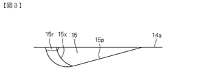
- FIG. 3 is a cross-sectional perspective view of the engagement groove 15 as viewed in the direction connecting the other end 15b from the one end 15a.
- the engagement groove 15 includes a side wall surface 15x formed on a side surface of the engagement groove 15 from one end 15a to the other end 15b of the engagement groove 15, and a radially inner side with respect to the side wall surface 15x. And a formed slope 15p.
- the end surface 2s of the component 2 can come into contact with the inclined surface 15p.
- the inclination of the inclined surface 15p with respect to the reference surface 14a is, for example, 30 degrees.
- the radial width W1 (see FIG. 2) of the engagement groove 15 is larger than the length W between the pair of side surfaces 2u and 2v facing each other. It is made smaller than the length L between the end faces 2s and 2t facing each other.
- the end 15r on the other end 15b side of the engaging groove 15 is formed gently so that the part 2 does not get caught when the part 2 escapes from the engaging groove 15.
- the material of the base 14 can be selected from metal, resin, glass, ceramics such as zirconia.
- the second main surface 10b of the rotor 10 is formed with a suction hole 13 that communicates with the radially inner ends of the cavities 12, 12a to 12f as suction means. .
- the inner diameter of the suction hole 13 is 10 to 90% of the thickness of the rotor.
- FIGS. 2, 4, and 5 are cross-sectional views of the main part of posture conversion.
- the radially inner side 13 s of the suction hole 13 communicates with a suction groove 14 s formed on the reference surface 14 a of the base 14.
- the suction groove 14s is connected to a reduced pressure source through an opening 14t formed on the bottom surface of the suction groove 14s, and sucks in the direction indicated by the arrow 80 in FIGS.
- the component 2 accommodated in the cavities 12a to 12f is sucked toward the radially inner end of the cavity.
- the component 2 is sucked in the direction opposite to the direction biased by the biasing member 20.
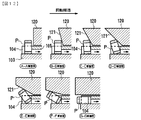
- FIGS. 4 and 5 show the process of posture change.
- 4 (a) to 4 (c) and FIGS. 4 (d) to (f) correspond to the cross-sectional positions of the cavities 12a to 12f, respectively.
- the component 2 supplied to the cavity 12a by the component supply unit is in an upright posture in which the end surface 2s contacts the reference surface 14a.
- the contact surface 20s of the biasing member 20 contacts the part 2p of the component 2 protruding from the first main surface 10a of the rotor 10.
- the contact surface 20 s urges a part 2 p of the part 2, and the corner of the part 2 on the valley side of the slope 15 p of the engaging groove 15 or
- the component 2 is rotated around the round corner 2q, the end surface 2s is separated from the inclined surface 15p of the engagement groove 15, and the component 2 is tilted. That is, the component 2 falls down radially outward.
- the component 2 is first sucked by the lower portion of the side surface 2v by the suction from the suction hole 13, and the suction force is applied in the direction in which the standing posture of the component 2 is maintained. It is working.
- the end face 2s is sucked radially inward, so that the suction from the suction hole 13 causes the component 2 to be in a sideways posture.
- the component 2 By suction from the suction hole 13, the component 2 can be attracted to the radially inner ends of the cavities 12, 12 a to 12 f to prevent positional displacement of the component 2, and the posture change of the component 2 can be stabilized.
- the suction from the suction hole 13 can prevent the component 2 from falling off or being displaced from the cavities 12, 12a to 12f, so that the direction of the reference surface 14a can be arbitrarily selected.
- the reference surface 14a can be tilted from the horizontal or set in the vertical direction.
- Example 2 The alignment apparatus of Example 2 will be described.
- the alignment apparatus of the second embodiment has substantially the same configuration as that of the first embodiment, and is different from the first embodiment in that the component supply unit supplies components to the cavity without aligning the orientation of the components.
- the components whose end surfaces abut against the reference surface are attached to the urging member when passing through the engaging groove, as in the first embodiment.
- the posture is converted into a posture in which the side surface abuts on the reference surface after rotating by the force and passing through the engaging groove.
- those whose side surfaces abut against the reference surface pass through the engaging groove without abutting against the biasing member. For this reason, even after passing through the engaging groove, the side surface is in a posture in contact with the reference surface, and the posture is not converted.
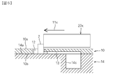
- FIG. 6 is a cross-sectional view of the main part showing the configuration of the posture changing apparatus of Modification 1.
- the urging member 20x moves radially outward as indicated by an arrow 11x and protrudes from the first main surface 10a of the rotor 10 of the component 2.
- the urging member 20x comes into contact with the portion that is urged to urge the component 2 to fall.
- FIG. 7 is a perspective view of the main part showing the configuration of the posture changing apparatus of Modification 2.
- the rotor 10k has a plurality of concentric circular cavities 12 arranged at equiangular intervals, and the urging member 20k has a plurality of contact surfaces 20p, 20q, and 20r. In addition, it does not matter as a separate urging member for each contact surface 20p, 20q, 20r.
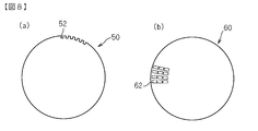
- FIGS. 8A and 8B are plan views showing a schematic configuration of the rotors 50 and 60 of Modification 3.
- FIG. 8A In the rotor 50 shown in FIG. 8A, a cavity 52 that penetrates between the principal surfaces of the rotor 50 facing each other is formed in a shape that is cut out along the outer periphery of the rotor 50.
- a plurality of concentric cavities 62 arranged at equal angular intervals are formed.
- FIGS. 8A and 8B only some of the cavities 52 and 62 are shown.
- FIG. 9 is a schematic diagram showing a schematic configuration of an endless belt 70 of Modification 4.
- the material of the endless belt 70 is resin, metal or the like.
- the base 76 can be disposed inside or outside the endless belt 70. In FIG. 9, only a part of the cavities 72 are shown. The cavity may have a shape cut out along the outer periphery of the endless belt 70.
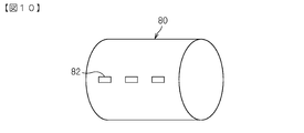
- FIG. 10 is a schematic diagram showing a schematic configuration of a rotating drum 80 of Modification 5.
- a cylindrical rotating drum 80 in which a cavity 82 is formed is used as a conveying member, and a base (not shown) is disposed inside or outside the rotating drum 80 and accommodated in the cavity 82.
- the material of the rotary drum 80 is a ceramic such as resin, metal, glass, zirconia.
- FIG. 10 shows only a part of the cavities 82.
- the engagement groove can suppress variations in the position of the rotation fulcrum when the posture of the component is converted, so that the posture of the component can be reliably converted.
- the suction means can also draw parts in the cavity by a method other than air suction, such as static electricity or magnetism.
Landscapes
- Engineering & Computer Science (AREA)
- Mechanical Engineering (AREA)
- Manufacturing & Machinery (AREA)
- Microelectronics & Electronic Packaging (AREA)
- Supply And Installment Of Electrical Components (AREA)
- Feeding Of Articles To Conveyors (AREA)
- Attitude Control For Articles On Conveyors (AREA)
- Manipulator (AREA)
Abstract
Description
2m,2n 側面
2p 一部
2q 角又は丸角
2s,2t 端面
2u,2v 側面
10,10k ロータ(搬送部材)
10a 第1の主面
10b 第2の主面
12,12a-12f キャビティ
13 吸引孔(吸引手段)
14 基台
14a 基準面
15 係合溝
15a 一端
15b 他端
15p 斜面
15x 側壁面
20,20k,20x 付勢部材
50 ロータ(搬送部材)
52 キャビティ
60 ロータ(搬送部材)
62 キャビティ
70 無端ベルト(搬送部材)
72 キャビティ
76 基台
80 回転ドラム(搬送部材)
82 キャビティ
Claims (6)
- 矩形形状の互いに対向する一対の端面と前記端面間を接続する4つの側面とを有する直方体形状の部品に用いる姿勢変換装置であって、
基準面と、前記基準面に対して溝状に形成された係合溝とを有し、前記係合溝は、前記係合溝の一端から他端を結ぶ方向と直交する方向に対して傾斜する斜面を含み、前記斜面は、前記一端から前記一端と前記他端との間の所定位置までの区間において前記部品の端面が当接可能に形成されている、基台と、
互いに対向する第1及び第2の主面と、前記第1及び第2の主面間を貫通するキャビティとを有し、前記第2の主面が前記基準面に対向し、前記キャビティが前記係合溝の前記一端から前記他端に順次対向するように、前記基台に対して相対移動し、前記キャビティは、前記部品の端面が前記基準面に当接するように前記部品を収容した後、前記部品が前記キャビティに収容された状態のまま移動して前記部品の側面が前記基準面に当接する姿勢になることができるように、かつ、前記所定位置において前記斜面に当接している前記部品の一部が、前記第1の主面から突出するように形成されている、搬送部材と、
前記所定位置において前記第1の主面から突出する前記部品の一部に当接し、前記基台に対する前記搬送部材の相対移動に伴って、前記部品を付勢し、前記斜面の谷側にある前記部品の角又は丸角を中心に前記部品を回転させて、前記部品の端面を前記斜面から離すように形成されている付勢部材と、
を備え、
前記キャビティに収容された前記部品が、前記基台に対する前記搬送部材の相対移動に伴って前記係合溝に沿って搬送されることによって、前記部品の端面が前記基準面に当接する姿勢から、前記側面が前記基準面に当接する姿勢に変換されることを特徴とする、姿勢変換整列装置。 - 前記キャビティに収容された前記部品を吸引する吸引手段をさらに備え、
前記吸引手段は、前記搬送部材の前記第2の主面側に設けられ、前記部品が前記当接部材により付勢される方向とは反対方向に前記部品を吸引することを特徴とする、請求項1に記載の姿勢変換装置。 - 請求項1又は2に記載の姿勢変換装置と、
前記部品を前記キャビティに供給する部品供給部と、
を備え、
前記部品供給部は、前記部品の端面が前記基準面に当接するようにも、前記部品の側面が前記基準面に当接するようにも、前記部品を前記キャビティに供給し、
前記端面が前記基準面に当接するように前記キャビティに供給された前記部品は、前記基台に対する前記搬送部材の相対移動に伴って前記係合溝に沿って搬送されるとともに前記付勢部材によって付勢されて、前記側面が前記基準面に当接する姿勢に変換され、
前記側面が前記基準面に当接するように前記キャビティに供給された前記部品は、前記基台に対する前記搬送部材の相対移動に伴って搬送されるが前記付勢部材によって付勢されることなく、前記側面が前記基準面に当接する姿勢のままであることを特徴とする、整列装置。 - 矩形形状の互いに対向する一対の端面と前記端面間を接続する4つの側面とを有する直方体形状の部品に用いる姿勢変換方法であって、
互いに対向する第1及び第2の主面と前記第1及び第2の主面間を貫通するキャビティとを有する搬送部材の前記キャビティに前記部品を収容する第1の工程と、
前記搬送部材を、基準面と前記基準面に対して溝状に形成された係合溝とを有する前記基台に対して相対移動させ、前記キャビティに収容されている前記部品を、前記係合溝の一端から他端まで順次対向させる第2の工程と、
を備え、
前記第2の工程は、
前記第1の工程で前記キャビティに収容された前記部品のうち前記端面が前記基準面に当接している前記部品の端面を、前記係合溝の前記一端から、前記一端と前記他端との間の所定位置まで、前記係合溝の前記一端から前記他端を結ぶ方向と直交する方向に対して傾斜する前記係合溝の斜面に当接させることによって、前記一端から前記所定位置に進むにつれて当該部品を前記基準面に対して傾ける第1のサブステップと、
前記所定位置において前記第1の主面から突出している当該部品の一部に付勢部材を当接させ、前記基台に対する前記搬送部材の相対移動に伴って、前記部品の一部を付勢し、前記係合溝の斜面の谷側にある当該部品の角又は丸角を中心に当該部品を回転させて、当該部品の前記端面を前記斜面から離し、当該部品をさらに傾ける第2のサブステップと、
を含み、
前記第2の工程後に、当該部品の姿勢は、前記側面が前記基準面に当接する姿勢に変換されていることを特徴とする、姿勢変換方法。 - 前記第2の工程において、前記キャビティに収容されている前記部品を、前記部品が前記当接部材により付勢される方向とは反対側方向に吸引することを特徴とする、請求項4に記載の姿勢変換方法。
- 請求項4又は5に記載の姿勢変換方法の前記第1の工程において、前記部品の端面が前記基準面に当接するようにも、前記部品の側面が前記基準面に当接するようにも、前記部品を前記キャビティに供給し、
前記第1の工程において前記端面が前記基準面に当接するように前記キャビティに供給された前記部品は、前記第2の工程後に、前記側面が前記基準面に当接する姿勢であり、
前記第1の工程において前記側面が前記基準面に当接するように前記キャビティに供給された前記部品は、前記第2の工程後に、前記側面が前記基準面に当接する姿勢であることを特徴とする、整列方法。
Priority Applications (4)
| Application Number | Priority Date | Filing Date | Title |
|---|---|---|---|
| JP2016507459A JP6238035B2 (ja) | 2014-03-13 | 2015-03-02 | 姿勢変換装置、整列装置及び姿勢変換方法、整列方法 |
| KR1020167023299A KR101784245B1 (ko) | 2014-03-13 | 2015-03-02 | 자세 변환 장치, 정렬 장치, 자세 변환 방법, 및 정렬 방법 |
| CN201580013509.2A CN106103317B (zh) | 2014-03-13 | 2015-03-02 | 姿势变换装置、排列装置及姿势变换方法、排列方法 |
| US15/259,367 US10029864B2 (en) | 2014-03-13 | 2016-09-08 | Attitude changing apparatus, aligning apparatus, attitude changing method and aligning method |
Applications Claiming Priority (2)
| Application Number | Priority Date | Filing Date | Title |
|---|---|---|---|
| JP2014-050204 | 2014-03-13 | ||
| JP2014050204 | 2014-03-13 |
Related Child Applications (1)
| Application Number | Title | Priority Date | Filing Date |
|---|---|---|---|
| US15/259,367 Continuation US10029864B2 (en) | 2014-03-13 | 2016-09-08 | Attitude changing apparatus, aligning apparatus, attitude changing method and aligning method |
Publications (1)
| Publication Number | Publication Date |
|---|---|
| WO2015137182A1 true WO2015137182A1 (ja) | 2015-09-17 |
Family
ID=54071630
Family Applications (1)
| Application Number | Title | Priority Date | Filing Date |
|---|---|---|---|
| PCT/JP2015/056128 Ceased WO2015137182A1 (ja) | 2014-03-13 | 2015-03-02 | 姿勢変換装置、整列装置及び姿勢変換方法、整列方法 |
Country Status (5)
| Country | Link |
|---|---|
| US (1) | US10029864B2 (ja) |
| JP (1) | JP6238035B2 (ja) |
| KR (1) | KR101784245B1 (ja) |
| CN (1) | CN106103317B (ja) |
| WO (1) | WO2015137182A1 (ja) |
Families Citing this family (3)
| Publication number | Priority date | Publication date | Assignee | Title |
|---|---|---|---|---|
| KR101871698B1 (ko) * | 2014-06-04 | 2018-06-27 | 가부시키가이샤 무라타 세이사쿠쇼 | 반송 장치 |
| CN111924483B (zh) * | 2020-07-09 | 2021-07-30 | 江苏安全技术职业学院 | 一种机械加工用翻料装置 |
| CN114291515B (zh) * | 2021-12-31 | 2025-08-15 | 广东晶科电子股份有限公司 | 振动盘双轨设计的进料装置 |
Citations (4)
| Publication number | Priority date | Publication date | Assignee | Title |
|---|---|---|---|---|
| JPS6424030U (ja) * | 1987-07-31 | 1989-02-09 | ||
| JP2000072230A (ja) * | 1998-09-01 | 2000-03-07 | Murata Mfg Co Ltd | チップ部品の姿勢変換装置 |
| WO2006027793A1 (en) * | 2004-07-07 | 2006-03-16 | Scitech Centre | An improved system for orientation and feeding articles for sealing and/or pharmaceutical machineries |
| JP2009249068A (ja) * | 2008-04-02 | 2009-10-29 | Aida Engineering Co Ltd | 集積装置 |
Family Cites Families (10)
| Publication number | Priority date | Publication date | Assignee | Title |
|---|---|---|---|---|
| US4822967A (en) * | 1987-03-10 | 1989-04-18 | Toppan Printing Co., Ltd. | Apparatus for sterilizing sealed food stuffs by microwave irradiation |
| JPH0315822U (ja) | 1989-06-28 | 1991-02-18 | ||
| JPH04345418A (ja) * | 1991-05-23 | 1992-12-01 | Shinken Seiki Kk | 天削箸の表裏を揃える装置 |
| JPH0595920A (ja) | 1991-10-11 | 1993-04-20 | Sharp Corp | 血圧計用カフ帯 |
| US5636960A (en) * | 1992-07-29 | 1997-06-10 | Tokyo Electron Limited | Apparatus for detecting and aligning a substrate |
| JPH0741976B2 (ja) * | 1992-08-06 | 1995-05-10 | 大同ほくさん株式会社 | 桟付ベルトコンベアによるテーパ付長尺物の端寄せ方法 |
| JPH08231031A (ja) * | 1995-02-23 | 1996-09-10 | Shinko Electric Co Ltd | 振動パーツフィーダ及びこれに使用される光ファイバセンサ |
| JP4887523B2 (ja) | 2000-12-28 | 2012-02-29 | リンテック株式会社 | 多面体検査用フィーダー及び多面体検査装置 |
| JP4563191B2 (ja) * | 2005-01-17 | 2010-10-13 | 大日本スクリーン製造株式会社 | 基板処理装置 |
| WO2015146502A1 (ja) * | 2014-03-27 | 2015-10-01 | 株式会社 村田製作所 | 姿勢変換装置・整列装置及び姿勢変換方法・整列方法 |
-
2015
- 2015-03-02 JP JP2016507459A patent/JP6238035B2/ja active Active
- 2015-03-02 CN CN201580013509.2A patent/CN106103317B/zh active Active
- 2015-03-02 KR KR1020167023299A patent/KR101784245B1/ko active Active
- 2015-03-02 WO PCT/JP2015/056128 patent/WO2015137182A1/ja not_active Ceased
-
2016
- 2016-09-08 US US15/259,367 patent/US10029864B2/en active Active
Patent Citations (4)
| Publication number | Priority date | Publication date | Assignee | Title |
|---|---|---|---|---|
| JPS6424030U (ja) * | 1987-07-31 | 1989-02-09 | ||
| JP2000072230A (ja) * | 1998-09-01 | 2000-03-07 | Murata Mfg Co Ltd | チップ部品の姿勢変換装置 |
| WO2006027793A1 (en) * | 2004-07-07 | 2006-03-16 | Scitech Centre | An improved system for orientation and feeding articles for sealing and/or pharmaceutical machineries |
| JP2009249068A (ja) * | 2008-04-02 | 2009-10-29 | Aida Engineering Co Ltd | 集積装置 |
Also Published As
| Publication number | Publication date |
|---|---|
| CN106103317A (zh) | 2016-11-09 |
| JP6238035B2 (ja) | 2017-11-29 |
| US10029864B2 (en) | 2018-07-24 |
| CN106103317B (zh) | 2017-12-12 |
| KR101784245B1 (ko) | 2017-10-11 |
| KR20160113246A (ko) | 2016-09-28 |
| JPWO2015137182A1 (ja) | 2017-04-06 |
| US20160376112A1 (en) | 2016-12-29 |
Similar Documents
| Publication | Publication Date | Title |
|---|---|---|
| JPWO2015146502A1 (ja) | 姿勢変換装置・整列装置及び姿勢変換方法・整列方法 | |
| TWI490154B (zh) | Electronic parts conveyor | |
| JP6238035B2 (ja) | 姿勢変換装置、整列装置及び姿勢変換方法、整列方法 | |
| CN104108590B (zh) | 非接触式基板传送旋转器 | |
| KR102668030B1 (ko) | 링 프레임의 유지 기구 | |
| TW201600858A (zh) | 搬運裝置 | |
| CN110031475B (zh) | 输送装置、输送方法及外观检查装置 | |
| JP2017050484A (ja) | ロボットハンド | |
| JP6292314B2 (ja) | 電子部品の搬送装置 | |
| KR20140120822A (ko) | 척 테이블 | |
| JP6578882B2 (ja) | 基板分割装置 | |
| JP6842948B2 (ja) | 位置決め装置および位置決め方法 | |
| JP5418795B2 (ja) | 電子部品搬送装置 | |
| KR101871698B1 (ko) | 반송 장치 | |
| CN108455164B (zh) | 传送组件及传送装置 | |
| JP6127728B2 (ja) | 脆性材料基板の搬送ヘッド | |
| JP5300006B2 (ja) | 部品供給装置 | |
| JP2015153970A5 (ja) | ||
| JP2005254382A (ja) | ワークの分離搬送装置及びワークの分離搬送方法 | |
| JP2006213374A (ja) | キャリアテープ | |
| WO2018020614A1 (ja) | 振子センサユニット、基板検出装置及び基板搬送装置 | |
| JP2006213371A (ja) | キャリアテープおよびその封止方法 |
Legal Events
| Date | Code | Title | Description |
|---|---|---|---|
| 121 | Ep: the epo has been informed by wipo that ep was designated in this application |
Ref document number: 15762320 Country of ref document: EP Kind code of ref document: A1 |
|
| ENP | Entry into the national phase |
Ref document number: 2016507459 Country of ref document: JP Kind code of ref document: A |
|
| ENP | Entry into the national phase |
Ref document number: 20167023299 Country of ref document: KR Kind code of ref document: A |
|
| NENP | Non-entry into the national phase |
Ref country code: DE |
|
| 122 | Ep: pct application non-entry in european phase |
Ref document number: 15762320 Country of ref document: EP Kind code of ref document: A1 |