WO2015133427A1 - 光学式温度センサ及び光学式温度センサの製造方法 - Google Patents
光学式温度センサ及び光学式温度センサの製造方法 Download PDFInfo
- Publication number
- WO2015133427A1 WO2015133427A1 PCT/JP2015/056058 JP2015056058W WO2015133427A1 WO 2015133427 A1 WO2015133427 A1 WO 2015133427A1 JP 2015056058 W JP2015056058 W JP 2015056058W WO 2015133427 A1 WO2015133427 A1 WO 2015133427A1
- Authority
- WO
- WIPO (PCT)
- Prior art keywords
- temperature
- temperature sensor
- light
- optical
- led
- Prior art date
- Legal status (The legal status is an assumption and is not a legal conclusion. Google has not performed a legal analysis and makes no representation as to the accuracy of the status listed.)
- Ceased
Links
Images


Classifications
-
- G—PHYSICS
- G01—MEASURING; TESTING
- G01K—MEASURING TEMPERATURE; MEASURING QUANTITY OF HEAT; THERMALLY-SENSITIVE ELEMENTS NOT OTHERWISE PROVIDED FOR
- G01K11/00—Measuring temperature based upon physical or chemical changes not covered by groups G01K3/00, G01K5/00, G01K7/00 or G01K9/00
- G01K11/12—Measuring temperature based upon physical or chemical changes not covered by groups G01K3/00, G01K5/00, G01K7/00 or G01K9/00 using changes in colour, translucency or reflectance
- G01K11/125—Measuring temperature based upon physical or chemical changes not covered by groups G01K3/00, G01K5/00, G01K7/00 or G01K9/00 using changes in colour, translucency or reflectance using changes in reflectance
-
- G—PHYSICS
- G01—MEASURING; TESTING
- G01K—MEASURING TEMPERATURE; MEASURING QUANTITY OF HEAT; THERMALLY-SENSITIVE ELEMENTS NOT OTHERWISE PROVIDED FOR
- G01K1/00—Details of thermometers not specially adapted for particular types of thermometer
- G01K1/08—Protective devices, e.g. casings
-
- G—PHYSICS
- G01—MEASURING; TESTING
- G01K—MEASURING TEMPERATURE; MEASURING QUANTITY OF HEAT; THERMALLY-SENSITIVE ELEMENTS NOT OTHERWISE PROVIDED FOR
- G01K1/00—Details of thermometers not specially adapted for particular types of thermometer
- G01K1/14—Supports; Fastening devices; Arrangements for mounting thermometers in particular locations
Definitions
- the present invention relates to an optical temperature sensor and a method for manufacturing the optical temperature sensor.
- An optical temperature sensor using a temperature sensing element composed of a semiconductor whose energy gap varies in response to a temperature change is known (for example, see Patent Documents 1 to 5).
- the optical temperature sensor transmits the signal light emitted from the first light emitting element and the reference light emitted from the second light emitting element to the temperature sensing element, and the signal light and the reference light transmitted through the temperature sensing element.
- the external temperature is detected based on each light intensity.
- the detection value by the optical temperature sensor may vary due to the structure of the temperature sensor.
- the accuracy, responsiveness, and stability of the measured value depend on the environmental temperature of the temperature measuring device and individual differences in parts. May get worse.
- An object of the present invention is to provide an optical temperature sensor and a temperature measuring device that are excellent in responsiveness and stability and can improve temperature measurement accuracy.
- a temperature sensing element whose light transmission characteristics change according to temperature; and A hollow holder for holding the temperature sensing element; An optical fiber that is provided inside the holding body and has a distal end surface facing the temperature sensing element at a position spaced apart from the temperature sensing element by a predetermined distance; The temperature sensing element receives light emitted from the tip surface of the optical fiber, transmits the incident light, and transmits the reflected light reflected by the measurement object.
- An optical temperature sensor is provided.
- a manufacturing method of the optical temperature sensor Holding the temperature sensing element on the holder; Rotating the holding body in a state in which a tip surface of the optical fiber is separated from the temperature sensing element, and optimizing a facing position between the temperature sensing element and the optical fiber; Placing the optical fiber at the optimized position facing the temperature sensing element at a predetermined distance; and A method of manufacturing an optical temperature sensor having
- an optical temperature sensor and a temperature measuring device that are excellent in responsiveness and stability and can improve temperature measurement accuracy.
- FIG. 1 is an overall configuration diagram of an optical temperature sensor according to an embodiment.
- An example of the temperature measurement result (stability) which concerns on one Embodiment.
- An example of the temperature measurement result (responsiveness) which concerns on one Embodiment.
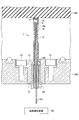
- FIG. 1 is an overall configuration diagram of an optical temperature sensor 1 according to an embodiment.
- the optical temperature sensor 1 is a temperature sensor using an optical fiber, and uses a semiconductor compound chip (thermosensitive material) whose optical absorption wavelength varies with temperature. That is, the optical temperature sensor 1 is a semiconductor absorption wavelength type temperature sensor that detects a temperature by using a heat sensitive body in which an absorption wavelength of light that is transmitted changes depending on the temperature.
- the optical temperature sensor 1 includes a heat sensitive body 10, a heat transfer aluminum plate 11, a holding cylinder 12, an optical fiber 13, a fixing member 14, and a spring 15.
- the thermal element 10 is formed of a gallium arsenide GaAs compound semiconductor.
- An aluminum reflection film is formed on the upper surface of the heat sensitive body 10, and an antireflection film is formed on the lower surface.
- the heat sensitive body 10 is an example of a temperature sensing element whose light transmission characteristics change according to temperature.
- the temperature sensing element is not limited to a gallium arsenide GaAs compound semiconductor as long as the light transmission characteristics change according to temperature.
- the upper surface of the heat sensitive body 10 is fixed to the heat transfer aluminum plate 11 having a high thermal conductivity by an adhesive.
- the structure of the tip portion of the optical temperature sensor 1 will be described.
- the tip of the holding cylinder 12 is opened, and the heat transfer aluminum plate 11 to which the heat sensitive body 10 is bonded is fitted into the opening. As a result, the opening of the holding cylinder 12 is closed, and the heat sensitive body 10 is fixed to the tip of the holding cylinder 12 in the holding cylinder 12.
- the holding cylinder 12 has a cylindrical shape, and the optical fiber 13 is held inside.
- the holding cylinder 12 is an example of a holding body that holds a temperature sensing element.
- the holding body may not be cylindrical as long as it is a hollow member capable of holding the optical fiber 13.
- the optical fiber 13 has a two-core structure.
- the fixing member 14 is fixed to the holding cylinder 12 with an adhesive while surrounding the optical fiber 13. Thereby, the optical fiber 13 is arranged so that the front end surface is positioned at the front end portion of the optical temperature sensor 1 in the vertical direction.
- an electrostatic chuck (ESC) is cited as an example of the temperature measurement object 205.
- the temperature of the temperature measurement object 205 is transmitted to the heat sensitive body 10 through the heat transfer aluminum plate 11. Therefore, when heat exchange is performed between the holding cylinder 12, the optical fiber 13, the fixing member 14, and the heat sensitive body 10, an error occurs in the temperature (detected value) of the temperature measurement object 205 detected by the heat sensitive body 10.
- the accuracy as a temperature sensor is deteriorated.
- the optical temperature sensor 1 has a structure in which the heat sensitive body 10, the optical fiber 13, and the distal end surface of the fixing member 14 do not contact each other. That is, the front end surface of the optical fiber 13 is disposed to face the heat sensitive body 10 at a position separated from the heat sensitive body 10 by a predetermined distance. Thereby, the hollow part S is formed in the surface where the front-end
- the distance between the heat sensitive body 10 and the tip surface of the optical fiber 13 is determined by rotating the holding cylinder 12 with reference to a design value (for example, 2.55 mm to 2.65 mm). Fine-tune the facing position of and optimize it. The optimization of the distance in the specific manufacturing process will be described later in the method for manufacturing the optical temperature sensor 1.
- the optical temperature sensor 1 has a structure in which the temperature of the heat sensitive body 10 is not easily transmitted to the holding cylinder 12 or the optical fiber 13 side. Thereby, the improvement of the measurement accuracy of temperature and the improvement of the response speed with respect to the temperature change of a measuring object can be aimed at.
- the holding cylinder 12 to be bonded to the heat transfer aluminum plate 11 is made of a material having low thermal conductivity, excellent mechanical strength, and high heat resistance.
- the fixing member 14 is made of a material having low thermal conductivity, excellent mechanical strength, and high heat resistance.
- the holding cylinder 12 and the fixing member 14 may be formed of a resin structure (PPS: Polyphenylene sulfide) having a low thermal conductivity.
- the contact area between the holding cylinder 12 and the heat transfer aluminum plate 11 is made as small as possible to suppress heat transfer.
- the holding cylinder 12 and the fixing member 14 are formed as thin as possible so that heat conduction is reduced.
- the fixing member 14 is formed so that the diameter (thickness) in the vicinity of the tip near the heat sensitive body 10 is smaller than the diameter (thickness) in the lower part.
- the fixing member 14 is formed with the shoulder dropping portion 14a for reducing the thickness as much as possible in the vicinity of the tip portion close to the heat sensitive body 10.
- the shoulder dropping part 14a a space is formed between the side part of the fixing member 14 and the holding cylinder 12, and the contact area between the fixing member 14 and the holding cylinder 12 can be reduced.
- the lower portion of the holding cylinder 12 is formed with a protruding portion 12b having a diameter larger than that of the upper portion of the holding cylinder 12 and protruding outward.
- a spring 15 is provided in the space between the optical fiber 13 in the holding cylinder 12 and the holding cylinder 12 formed by the protruding portion 12b.
- the holding cylinder 12 is fitted into an aluminum flange 21 and fixed by, for example, fixing the flange 21 to the mounting table 200 with screws 22 and 23.
- An aluminum bush 24 is provided below the flange 21.
- the spring 15 is fixed to the upper surface of the bush 24 by fixing the flange 21 with screws 22 and 23.
- the temperature of the temperature measurement object 205 is transmitted to the heat sensitive body 10 through the heat transfer aluminum plate 11.
- the holding cylinder 12 is pushed upward by the expansion and contraction of the spring 15, and the tip of the optical temperature sensor 1 is pressed against the lower surface of the temperature measurement object 205.
- the heat transfer aluminum plate 11 is pressed against the lower surface of the temperature measurement object 205 to stably transfer heat between the temperature measurement object 205 and the heat transfer aluminum plate 11, and the temperature detection by the heat sensitive body 10.
- the strength of the reaction force of the spring 15 is the minimum force that can provide a sufficient contact area between the heat transfer aluminum plate 11 and the temperature measurement object 205 and can stably measure the temperature of the temperature measurement object 205. And the strength is set so that excessive force is not applied to the temperature measurement object 205.
- the LED light output from the temperature measuring device 30 passes through the optical fiber 13, passes through the heat sensitive body 10, reflects off the lower surface of the temperature measuring object 205, passes through the heat sensitive body 10 again, and passes through the optical fiber 13. And is received by the temperature measuring device 30.
- FIG. 2 shows a method for manufacturing an optical temperature sensor according to an embodiment.
- a notch 12 a is formed on the side surface of the tip of the holding cylinder 12 as shown in the bottom view of FIG. 2.
- the gallium arsenide GaAs heat sensing element 10 is bonded to the lower surface of the heat transfer aluminum plate 11.
- the heat transfer aluminum plate 11 is bonded to the holding cylinder 12 so as to close the opening at the tip of the holding cylinder 12.
- the optical temperature sensor 1 is searched for an appropriate position in the rotational direction of the thermal sensor 10 where there is almost no individual difference, and the tip surface of the optical fiber 13 and the thermal sensor. An appropriate distance D with 10 is searched.
- the side wall of the fixing member 14 is bonded to the holding cylinder 12 in a state where the facing position (distance D) between the heat sensitive body 10 and the distal end face of the optical fiber 13 that are optimized as a result of the search is held.
- the hollow portion S having the distance D is formed between the tip surface of the optical fiber 13 and the heat sensitive body 10.
- the distance D between the front end surface of the optical fiber 13 and the heat sensitive body 10 has a design reference value.
- the position of the tip surface of the optical fiber 13 is finely adjusted up and down while rotating the holding cylinder 12 with the tip surface of the optical fiber 13 being separated from the heat sensitive body 10. To do.
- the distance D between the front end surface of the optical fiber 13 and the thermosensitive body 10 can be finely adjusted from the design reference value. it can.
- the opposing position of the heat sensitive body 10 and the front end surface of the optical fiber 13 is optimized.
- the optical temperature sensor 1 detects the temperature by using a heat sensitive body 10 whose optical absorption wavelength varies depending on the temperature.
- the position and angle when the thermosensitive member 10 is bonded to the heat transfer aluminum plate 11 are not necessarily constant.
- the amount (measured value) of the light reflected through the heat sensitive body 10 is specified by finely adjusting the distance D between the tip surface of the optical fiber 13 and the heat sensitive body 10 while rotating the holding cylinder 12. So that the light intensity is as high as possible.
- tip part of the optical temperature sensor 1 containing the thermosensitive body 10 is reduced.
- the individual difference of the optical temperature sensor 1 can be reduced, and the precision of the temperature measured by the optical temperature sensor 1 can be improved.
- step e the side surface of the tip portion of the optical temperature sensor 1 is viewed from the CC plane shown in step d.
- a cutout portion 12 a is formed on the side surface of the distal end portion of the holding cylinder 12.
- the notch portion 12a communicates with the hollow portion S.
- dry air may be flowed from the notch 12a into the hollow portion S, and the dry air may be circulated to a position where the heat sensitive body 10 is attached.
- the dry air may be circulated to a position where the heat sensitive body 10 is attached.
- the configuration of the optical temperature sensor 1 according to the present embodiment and the manufacturing method thereof have been described above.
- light emitted from the end face of the optical fiber 13 is transmitted through the heat sensitive body 10.
- the transmitted light is reflected on the surface of the heat transfer aluminum plate 11 that contacts the measurement object.
- the reflected light again passes through the heat sensitive body 10 and enters the optical fiber 13 from the end face of the optical fiber 13.
- the incident reflected light is output to the temperature measuring device 30 through the optical fiber 13.
- the temperature measuring device 30 measures the wavelength of the light absorbed by the thermal element 10 based on the input reflected light, and converts it to a temperature. Thereby, the temperature of the temperature measurement object 205 is measured.
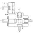
- FIG. 3 is a block diagram of a temperature measurement device according to an embodiment.
- the temperature measuring device 30 includes a light projecting / receiving module 100, a measurement light LED driver 40, a reference light LED driver 41, a measurement PD (photodiode) amplifier 42, a LED monitor PD amplifier 43, and a 16-bit A. / D converter 44, control unit 50, LED temperature amplifier 52, and heater driver 53.
- the light projecting / receiving module 100 includes a light projecting unit (light projecting module) 2 that outputs light for measurement and reference, and reflected light having a wavelength absorbed by the heat sensitive body 10 of the optical temperature sensor 1 (reflected light of measurement light and And a light receiving unit (light receiving module) 3 that receives reflected light for reference).
- a light projecting unit light projecting module 2 that outputs light for measurement and reference, and reflected light having a wavelength absorbed by the heat sensitive body 10 of the optical temperature sensor 1 (reflected light of measurement light and
- a light receiving unit (light receiving module) 3 that receives reflected light for reference).
- the light projecting unit 2 includes a measurement LED 31, a reference LED 32, a beam splitter 33, an LED SiPD (silicon photodiode) 34, and an optical connector 35.
- the light receiving unit 3 includes a measurement SiPD 36 and an optical connector 37.
- the measurement LED 31 outputs measurement light having a first wavelength.
- the measurement LED 31 outputs light (measurement light) in a wavelength band in which the amount of light transmitted through the thermal body 10 changes according to the temperature change of the thermal body 10.
- the reference LED 32 outputs reference light having the second wavelength.
- the reference LED 32 has a constant amount of light transmitted through the heat sensitive body 10 regardless of the temperature of the heat sensitive body 10, and light in a wavelength band that does not change the amount of light transmitted through the heat sensitive body 10 according to the temperature change of the heat sensitive body 10 (see Light).
- the beam splitter 33 transmits a part of the incident measurement light and reference light and reflects a part thereof.
- the light transmitted through the beam splitter 33 is transmitted to the optical temperature sensor 1 through the optical fiber 13 connected to the optical connector 35.
- the reflected light of the beam splitter 33 enters an LED SiPD (silicon photodiode) 34.
- the LED SiPD 34 is a photodiode for light projection confirmation, and outputs current values corresponding to the amount of measurement light and the amount of reference light.
- the measurement SiPD 36 receives the reflected light from the optical temperature sensor 1 through the optical fiber 13 connected to the optical connector 37.
- the measurement SiPD 36 outputs a current value corresponding to the amount of the input reflected light.
- the LED monitor PD amplifier 43 converts the current value output from the LED SiPD 34 into a voltage and amplifies it.
- the 16-bit A / D converter 44 converts the analog value of the voltage output from the LED monitor PD amplifier 43 into a digital value, and inputs the converted digital value to the control unit 50 as a monitor value.
- the control unit 50 controls the output value of the LED (measurement LED 31 or reference LED 32) whose monitor value is changing when the monitor value is changed.
- the control signal for changing the output value is output as a pulse value from the PWM dimming of the control unit 50.
- the control unit 50 includes a CPU 50a (Central Processing Unit), a ROM 50b (Read Only Memory), a RAM 50c (Random Access Memory), and the like.
- the CPU 50a performs temperature calculation and temperature management according to various data stored in a storage area such as the ROM 50b.
- the function of the control unit 50 may be realized by operating using software, or may be realized by operating using hardware.
- the LED driver for measurement light 40 feedback-controls the current that actually flows through the measurement LED 31 according to the pulse width of the control signal output from the control unit 50.
- the LED driver 41 for reference light feedback-controls the current that actually flows through the reference LED 32 according to the pulse width of the control signal output from the control unit 50.
- the measurement LED 31 and the reference LED 32 output a certain amount of measurement light and reference light based on the feedback-controlled current value.
- the emission intensity of two types of LEDs for measurement and reference used as a light source is measured by the LED SiPD 34, and feedback control is performed so that the light amounts of the measurement light and the reference light are always constant.
- the amount of reference light can be controlled to be constant.
- the measurement SiPD 36 receives the reflected light from the optical temperature sensor 1 through the optical fiber 13 connected to the optical connector 37.
- the measurement SiPD 36 outputs a current value corresponding to the amount of the input reflected light.
- the measurement PD amplifier 42 converts the current value output from the measurement SiPD 36 into a voltage and amplifies it.
- the 16-bit A / D converter 44 converts the analog value of the voltage output from the measurement PD amplifier 42 into a digital value, and uses the converted digital value as a measured value detected by the optical temperature sensor 1. To enter.
- the controller 50 converts the temperature from the measured value.
- FIG. 5 is a flowchart illustrating a temperature measurement method according to an embodiment.
- the time T1 shown in the lower frame of FIG. 3 for measurement in a state where no light is output from either the measurement LED 31 or the reference LED 32 The output value (initial value) of the SiPD 36 is measured.
- the reflected light (return light) that is returned when light is output from the measurement LED 31 (LED1) is measured by the measurement SiPD 36.
- the reflected light that is returned when light is output from the reference LED 32 (LED2) is measured by the measurement SiPD 36.
- the output value (initial value) measured by the measurement SiPD 36 at time T1 is usually a value close to “0”, but when it exceeds a predetermined threshold, it is output from the measurement LED 31 at time T2.
- the measurement value of the measurement light is corrected by subtracting the output value (initial value) from the measurement value of the reflected light with respect to the reflected light.
- the measured value of the reference light is obtained by subtracting the output value (initial value) from the measured value of the reflected light with respect to the light output from the reference LED 32 at time T3. to correct.
- the temperature measurement method described below the temperature measurement method when this correction does not occur will be described, and the description when the correction occurs will be omitted.
- step S31 measurement light having a first wavelength is output from the measurement LED 31 (LED 1).
- the measurement light passes through the optical fiber 13, is emitted from the front end surface of the optical fiber 13, and passes through the heat sensitive body 10.
- the measurement light is light in a wavelength band (first wavelength) in which the amount of transmitted light changes when the temperature of the heat sensitive body 10 changes.
- the transmitted measurement light is reflected by the heat transfer aluminum plate 11 (contact surface with the measurement object).
- the reflected light of the measurement light again passes through the heat sensitive body 10 and enters the optical fiber 13 from the tip surface of the optical fiber 13.
- step S32 the measurement SiPD 36 receives the reflected light (returned light) from the optical temperature sensor 1 received through the optical fiber 13.
- the measurement SiPD 36 outputs a current value I1 corresponding to the amount of light.
- the reference light of the second wavelength is output from the reference LED 32 (LED2).
- the reference light passes through the optical fiber 13, is emitted from the front end surface of the optical fiber 13, and passes through the heat sensitive body 10.
- the reference light is light in a wavelength band (second wavelength) in which the amount of transmitted light does not change even when the temperature of the heat sensitive body 10 changes.
- the transmitted measurement light is reflected by the heat transfer aluminum plate 11 (contact surface with the measurement object).
- the reflected light of the reference light again passes through the heat sensitive body 10 and enters the optical fiber 13 from the tip surface of the optical fiber 13.
- step S34 the measurement SiPD 36 receives the reflected light (return light) from the optical temperature sensor 1 received through the optical fiber 13.
- the measurement SiPD 36 outputs a current value I2 corresponding to the amount of light.
- step S35 the control unit 50 obtains a ratio between the current value I1 measured from the reflected light of the measurement light and the current value I2 measured from the reflected light of the reference light, and converts it to a temperature. Output.
- the temperature of the temperature measurement object 205 detected by the optical temperature sensor 1 is based on the reflected light of the measurement light and the reflected light of the reference light. Calculated.
- the temperature measurement device 30 of the present embodiment can measure temperature at a cycle of about 8.3 milliseconds.
- the temperature can be measured in a short time compared to the general temperature measurement that can be performed in a cycle of about 40 milliseconds.
- a mechanism for separately controlling the temperature of the measurement LED 31 and the reference LED 32 is provided.
- a temperature adjustment unit including a mechanism for separately adjusting the temperature of the measurement LED 31 and the reference LED 32 will be described with reference to FIGS. 3 and 6.
- the temperature adjustment unit includes a temperature sensor 38 and a temperature adjustment mechanism 6 included in the light projecting / receiving module 100, an LED temperature amplifier 52, a heater driver 53, and a control unit 50.
- the temperature control of the LED 31 for use and the temperature control of the reference LED 32 are performed separately.
- a measurement LED 31 and a reference LED 32 are arranged inside the light projecting unit 2.
- Each of the measurement LED 31 and the reference LED 32 is provided with a temperature control function. Specifically, the temperature control function will be described.
- the outer periphery of the measurement LED 31 is covered with a cylindrical member 60 as shown in the central view of FIG.
- the outer periphery of the reference LED 32 is covered with a cylindrical member 63.
- the cylindrical members 60 and 63 are made of, for example, aluminum.
- Peltier elements 61 and 65 are placed above the cylindrical members 60 and 63 with aluminum plates 62 and 64 having a thickness of about 1 mm interposed therebetween. As shown in the central view of FIG. 6, the Peltier element 61 (the description is omitted because the Peltier element 65 is the same) is heated from one metal to the other when an electric current is passed through a junction of two kinds of metals. Has the property of moving, thereby generating heat absorption on one side and heat generation on the other side.
- the cylindrical member 60, the aluminum plate 62, and the Peltier element 61 are an example of the temperature adjustment mechanism 6 in FIG. 3, and the first light source that heats or cools the first light source based on the temperature of the first light source. Corresponds to the temperature control mechanism.
- the cylindrical member 63, the aluminum plate 64, and the Peltier element 65 are an example of the temperature control mechanism 6 in FIG. 3, and a second temperature control that heats or cools the second light source based on the temperature of the second light source. Corresponds to the mechanism.
- the temperature adjustment mechanism 6 may not have the aluminum plates 62 and 64.
- the current flowing through the Peltier element 61 is controlled based on the temperature detected by the temperature sensor 38 provided in the vicinity of the measurement LED 31, and is shown in the central view of FIG.
- the measurement LED 31 is heated through the aluminum plate 62 and the tubular member 60 having good heat conductivity.
- the current flowing through the Peltier element 61 is controlled based on the temperature detected by the temperature sensor 38 and the lower surface of the Peltier element 61 is absorbed, the measurement LED 31 is cooled through the aluminum plate 62 and the cylindrical member 60.
- the reference LED 32 can be heated and cooled by controlling the current flowing through the Peltier element 65.
- the measurement LED 31 and the reference LED 32 are locally temperature controlled. Therefore, the temperature of the measurement LED 31 and the reference LED 32 can be adjusted with a small amount of heat.
- cylindrical members 60 and 63 and the outer casing H are designed to be insulated so that the heat of the cylindrical members 60 and 63 does not escape to the outside. That is, a space is provided around the cylindrical members 60 and 63 to reduce the contact surface between the cylindrical members 60 and 63 and the housing H.
- a heat insulating ring (not shown) may be inserted between the cylindrical members 60 and 63 and the housing H.
- the Peltier element 61 may be placed on the aluminum plate 62 as shown in the upper right view of FIG. 6, or as a flat surface 60a on the upper portion of the tubular member 60 as shown in the lower right view of FIG. May be formed and placed thereon.
- the Peltier element 65 may be placed on the tubular member 63 without using the aluminum plate 64.
- the current value detected by the temperature sensor 38 is input to the LED temperature amplifier 52.
- the LED temperature amplifier 52 converts the current value into a voltage value, amplifies it, and outputs it to the control unit 50.
- the control unit 50 outputs a control signal for controlling the current value output to the heater according to the input voltage value.
- the heater driver 53 supplies a desired current to the Peltier elements 61 and 65 in FIG. 6 based on the control signal. As a result, the temperatures of the measurement LED 31 and the reference LED 32 are each controlled to a desired temperature.
- the temperature control of the measurement LED 31 and the reference LED 32 is performed separately and independently.
- the wavelength distribution has individual differences for each LED.
- the temperature of each LED is adjusted by the temperature control unit provided in each of the measurement LED 31 and the reference LED 32. Thereby, the individual difference and environmental temperature of LED 31 for a measurement and LED 32 for a reference can be absorbed.
- the temperature measuring device 30 is provided with the LED SiPD 34 shown in FIGS. 3 and 4.
- the LED SiPD 34 is a photodiode for light projection confirmation, and outputs a current value corresponding to the amount of measurement light output from the measurement LED 31.
- the LED monitor PD amplifier 43 converts the current value output from the LED SiPD 34 into a voltage, amplifies it, and outputs it to the control unit 50.
- the control unit 50 measures the amount of light output from the LED SiPD 34 according to the input voltage value, and controls the current to flow through the measurement LED 31 according to the decrease in the amount of light.
- the LED driver for measurement light 40 feedback-controls the value of the current that flows to the measurement LED 31 according to the pulse width of the control signal output from the control unit 50.
- the LED SiPD 34 outputs a current value corresponding to the amount of reference light output from the reference LED 32.
- the LED monitor PD amplifier 43 converts the current value output from the LED SiPD 34 into a voltage, amplifies it, and outputs it to the control unit 50.
- the control unit 50 measures the amount of light output from the LED SiPD 34 according to the input voltage value, and controls the current to flow through the reference LED 32 according to the decrease in the amount of light.
- the LED driver 41 for reference light feedback-controls the value of the current passed through the reference LED 32 according to the pulse width of the control signal output from the control unit 50.
- the amount of light output from the LED can be controlled to be constant according to changes in the LED over time.
- the LED SiPD 34 corresponds to a monitor unit for monitoring the light amounts of the measurement light and the reference light.
- the measurement LED 31 corresponds to a first light source that outputs measurement light having a first wavelength.
- the reference LED 32 corresponds to a second light source that outputs measurement light having a second wavelength.
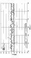
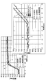
- Example of effects 7 to 9 show examples of temperature measurement results according to the present embodiment.
- the horizontal axis represents time (seconds)
- the vertical axis represents the temperature (° C.) of the surface of the temperature measurement object.
- FIG. 7 the detected value which each temperature sensor of this embodiment and the comparative examples 1 and 2 when the time shown on a horizontal axis passes without changing the temperature of the surface of a temperature measuring object is shown.
- the optical temperature sensor 1 according to the present embodiment has the least temperature variation as compared with the temperature sensors of Comparative Examples 1 and 2.
- the temperature sensor of the comparative example 1 has about twice the variation of the optical temperature sensor 1 according to the present embodiment, and the temperature sensor of the comparative example 2 is about three times that of the optical temperature sensor 1 according to the present embodiment. There is variation. From the above, it can be seen that the optical temperature sensor 1 according to the present embodiment is excellent in output characteristics and stability.
- the optical temperature sensor 1 of this embodiment and the temperature sensor of the comparative example 2 have higher responsiveness than the temperature sensor of the comparative example 1.
- the optical temperature sensor 1 of the present embodiment has less variation than the temperature sensor of Comparative Example 2. . From the above, it can be seen that the optical temperature sensor 1 of the present embodiment is excellent in output characteristics, stability and responsiveness.
- the optical temperature sensor 1 of this embodiment and the temperature sensor of the comparative example 2 have higher responsiveness than the temperature sensor of the comparative example 1.
- the optical temperature sensor 1 of the present embodiment has less variation than the temperature sensor of Comparative Example 2. From the above, it can be seen that the optical temperature sensor 1 of the present embodiment is excellent in output characteristics, stability and responsiveness to temperature fluctuations in a relatively high temperature region.
- the optical fiber front end surface and the heat sensitive body are arranged to face each other at a position separated by a predetermined distance.
- an optical temperature sensor excellent in accuracy, responsiveness and stability can be provided.
- fills predetermined performance can be provided.
- temperature measurement is possible in a short time.
- the light amounts of the measurement light and the reference light output from the measurement LED 31 and the reference LED 32 can be controlled to be constant. Thereby, the secular change as the temperature measuring device 30 is suppressed, temperature measurement with high accuracy is enabled, and the life of the temperature measuring device 30 can be extended.
- the temperature of each LED is adjusted by the temperature control unit provided in each of the measurement LED 31 and the reference LED 32.
- the individual difference and environmental temperature of LED 31 for a measurement and LED 32 for a reference can be absorbed.
- the optical temperature sensor and the method for manufacturing the optical temperature sensor have been described in the above embodiment.
- the temperature measuring device, the light projecting module, and the temperature measuring method have been described in the above embodiment.
- the present invention is not limited to the above embodiment, and various modifications and improvements can be made within the scope of the present invention. Moreover, it is possible to combine the above-described embodiments and modification examples as long as they do not contradict each other.
- the optical temperature sensor, the temperature measuring device, and the temperature measuring method according to the present invention are applied to temperature detection of an electrostatic chuck installed in an etching processing device, an ashing processing device, a film forming processing device, or other components. Is possible.
- Optical temperature sensor 2 Light projection part 3: Light-receiving part 6: Temperature control mechanism 10: Heat sensitive body 11: Aluminum plate for heat transfer 12: Holding cylinder 12a: Notch part 12b: Protrusion part 13: Optical fiber, 14: Fixing member 14a: Shoulder dropping part 15: Spring 30: Temperature measuring device 31: LED for measurement 32: LED for reference 33: Beam splitter 34: SiPD for LED 35: Optical connector 36: SiPD for measurement 37: Optical connector 38: Temperature sensor 40: LED driver for measurement light 41: LED driver for reference light 42: PD amplifier for measurement 43: PD amplifier for LED monitor 44: 16-bit A / D converter 50: Control unit 52: LED Temperature amplifier 53: Heater driver 60, 63: Cylindrical member 61, 65: Peltier element 62, 64: Aluminum plate 100: Light emitting / receiving module
Landscapes
- Physics & Mathematics (AREA)
- General Physics & Mathematics (AREA)
- Measuring Temperature Or Quantity Of Heat (AREA)
Priority Applications (1)
| Application Number | Priority Date | Filing Date | Title |
|---|---|---|---|
| US15/116,569 US10139290B2 (en) | 2014-03-04 | 2015-03-02 | Optical temperature sensor and method for manufacturing optical temperature sensor |
Applications Claiming Priority (2)
| Application Number | Priority Date | Filing Date | Title |
|---|---|---|---|
| JP2014042137A JP6233707B2 (ja) | 2014-03-04 | 2014-03-04 | 光学式温度センサ及び光学式温度センサの製造方法 |
| JP2014-042137 | 2014-03-04 |
Publications (1)
| Publication Number | Publication Date |
|---|---|
| WO2015133427A1 true WO2015133427A1 (ja) | 2015-09-11 |
Family
ID=54055233
Family Applications (1)
| Application Number | Title | Priority Date | Filing Date |
|---|---|---|---|
| PCT/JP2015/056058 Ceased WO2015133427A1 (ja) | 2014-03-04 | 2015-03-02 | 光学式温度センサ及び光学式温度センサの製造方法 |
Country Status (4)
| Country | Link |
|---|---|
| US (1) | US10139290B2 (enExample) |
| JP (1) | JP6233707B2 (enExample) |
| TW (1) | TWI663385B (enExample) |
| WO (1) | WO2015133427A1 (enExample) |
Families Citing this family (6)
| Publication number | Priority date | Publication date | Assignee | Title |
|---|---|---|---|---|
| US20170128158A1 (en) * | 2014-11-12 | 2017-05-11 | Dxm Co., Ltd | Dental material heating infuser for heating dental material by peltier element |
| JP6736042B2 (ja) * | 2016-09-09 | 2020-08-05 | 株式会社シミウス | Fbg温度センサ |
| WO2018057620A1 (en) * | 2016-09-20 | 2018-03-29 | Lumasense Technologies Holdings, Inc. | Temperature probe |
| CN110400772B (zh) * | 2018-04-24 | 2021-10-15 | 北京北方华创微电子装备有限公司 | 静电卡盘和半导体加工设备 |
| WO2020020564A1 (en) * | 2018-07-24 | 2020-01-30 | Asml Netherlands B.V. | Substrate positioning device with remote temperature sensor |
| JP7329338B2 (ja) * | 2019-03-05 | 2023-08-18 | セイコーグループ株式会社 | 口腔内生体モニタリング装置 |
Citations (1)
| Publication number | Priority date | Publication date | Assignee | Title |
|---|---|---|---|---|
| JP2007184564A (ja) * | 2005-12-06 | 2007-07-19 | Tokyo Electron Ltd | 基板処理装置における被測定物の物理量測定方法及び記憶媒体 |
Family Cites Families (17)
| Publication number | Priority date | Publication date | Assignee | Title |
|---|---|---|---|---|
| US4703174A (en) * | 1984-03-02 | 1987-10-27 | Fiberdynamics, Inc. | Fiberoptic temperature/pressure sensor system |
| JPS61213738A (ja) | 1985-03-20 | 1986-09-22 | Nagoyashi | 光フアイバ温度計測センサ |
| JPS61233331A (ja) | 1985-04-08 | 1986-10-17 | Mitsubishi Cable Ind Ltd | 光学式温度計 |
| JPS61232684A (ja) | 1985-04-08 | 1986-10-16 | Mitsubishi Cable Ind Ltd | 光半導体素子の温度安定化装置 |
| JPS6285832A (ja) | 1985-10-11 | 1987-04-20 | Mitsubishi Cable Ind Ltd | 光学式温度計 |
| JPH01242931A (ja) | 1988-03-23 | 1989-09-27 | Mitsubishi Electric Corp | 温度センサ |
| US5446279A (en) * | 1993-08-27 | 1995-08-29 | Hughes Aircraft Company | Fiber optic sensor sensing curvature of a diaphragm |
| US7080940B2 (en) * | 2001-04-20 | 2006-07-25 | Luxtron Corporation | In situ optical surface temperature measuring techniques and devices |
| US6572265B1 (en) * | 2001-04-20 | 2003-06-03 | Luxtron Corporation | In situ optical surface temperature measuring techniques and devices |
| US7056035B2 (en) * | 2001-12-21 | 2006-06-06 | The Furukawa Electric Co., Ltd. | Optical module, optical apparatus including optical module, and method for using optical module |
| TWI246589B (en) * | 2004-06-29 | 2006-01-01 | Univ Feng Chia | Lateral superstructure fiber grating pressure and temperature sensor |
| DE102008038875B3 (de) * | 2008-08-13 | 2010-01-28 | Abb Technology Ag | Temperaturfühler für eine prozesstechnische industrielle Anlage |
| DE102009010289A1 (de) * | 2009-02-24 | 2010-09-02 | Siemens Aktiengesellschaft | Vorrichtung zur Temperaturmessung in elektromagnetischen Feldern, Verwendung dieser Vorrichtung sowie zugehörige Messanordnung |
| US20110267598A1 (en) * | 2010-04-30 | 2011-11-03 | Vestas Wind Systems A/S | Optical sensor system and detecting method for an enclosed semiconductor device module |
| DE202011003569U1 (de) * | 2011-03-04 | 2012-06-05 | Horst Sonnendorfer | Messgerät |
| JP5730638B2 (ja) * | 2011-03-28 | 2015-06-10 | 東京エレクトロン株式会社 | 基板処理装置の処理室内構成部材及びその温度測定方法 |
| JP6263019B2 (ja) * | 2013-12-16 | 2018-01-17 | 東京エレクトロン株式会社 | 温度測定方法、基板処理システム及び温度測定用部材 |
-
2014
- 2014-03-04 JP JP2014042137A patent/JP6233707B2/ja active Active
-
2015
- 2015-03-02 WO PCT/JP2015/056058 patent/WO2015133427A1/ja not_active Ceased
- 2015-03-02 TW TW104106435A patent/TWI663385B/zh active
- 2015-03-02 US US15/116,569 patent/US10139290B2/en active Active
Patent Citations (1)
| Publication number | Priority date | Publication date | Assignee | Title |
|---|---|---|---|---|
| JP2007184564A (ja) * | 2005-12-06 | 2007-07-19 | Tokyo Electron Ltd | 基板処理装置における被測定物の物理量測定方法及び記憶媒体 |
Also Published As
| Publication number | Publication date |
|---|---|
| US20160363486A1 (en) | 2016-12-15 |
| US10139290B2 (en) | 2018-11-27 |
| JP2015169444A (ja) | 2015-09-28 |
| TWI663385B (zh) | 2019-06-21 |
| TW201546426A (zh) | 2015-12-16 |
| JP6233707B2 (ja) | 2017-11-22 |
Similar Documents
| Publication | Publication Date | Title |
|---|---|---|
| JP6233707B2 (ja) | 光学式温度センサ及び光学式温度センサの製造方法 | |
| JPH1065269A (ja) | レーザ送信機 | |
| JP7175264B2 (ja) | 光送信機 | |
| JP6593547B1 (ja) | 光モジュール | |
| JP6266384B2 (ja) | 温度測定装置及び温度測定方法 | |
| JP7127548B2 (ja) | 距離測定装置及びそのsn比を改善する方法 | |
| TWI646314B (zh) | 光學式溫度感測器及光學式溫度感測器之控制方法 | |
| US11099061B2 (en) | Measurement device for light-emitting device and method for measuring light-emitting device | |
| US10935425B2 (en) | Spectroscopic detector | |
| JP2008294262A (ja) | 光素子モジュール及びその製造方法 | |
| WO2006115856A2 (en) | Electro-optic transducer die mounted directly upon a temperature sensing device | |
| US20070127874A1 (en) | Optical module with thermo-electric controller in co-axial package | |
| JP5088866B2 (ja) | 波長ロッカー用温度制御装置、波長ロッカー及び光モジュール | |
| JP5005421B2 (ja) | 波長ロッカー用温度制御装置、波長ロッカー及び光モジュール | |
| JP2009289842A (ja) | 光デバイス | |
| JP2004153176A (ja) | 波長ロッカー | |
| JPH07302949A (ja) | 波長安定化装置 | |
| JP2008153529A (ja) | 光送信器 | |
| JP2011023727A (ja) | 発光光線の重心波長を調整するための装置 | |
| JP4603009B2 (ja) | 波長ロッカー | |
| WO2017221441A1 (ja) | 光通信デバイス | |
| JP2009065083A (ja) | 光モジュール | |
| US20060237807A1 (en) | Electro-optic transducer die including a temperature sensing PN junction diode |
Legal Events
| Date | Code | Title | Description |
|---|---|---|---|
| 121 | Ep: the epo has been informed by wipo that ep was designated in this application |
Ref document number: 15758899 Country of ref document: EP Kind code of ref document: A1 |
|
| WWE | Wipo information: entry into national phase |
Ref document number: 15116569 Country of ref document: US |
|
| NENP | Non-entry into the national phase |
Ref country code: DE |
|
| 122 | Ep: pct application non-entry in european phase |
Ref document number: 15758899 Country of ref document: EP Kind code of ref document: A1 |