WO2015133378A1 - 水素吸蔵合金の充填方法 - Google Patents
水素吸蔵合金の充填方法 Download PDFInfo
- Publication number
- WO2015133378A1 WO2015133378A1 PCT/JP2015/055712 JP2015055712W WO2015133378A1 WO 2015133378 A1 WO2015133378 A1 WO 2015133378A1 JP 2015055712 W JP2015055712 W JP 2015055712W WO 2015133378 A1 WO2015133378 A1 WO 2015133378A1
- Authority
- WO
- WIPO (PCT)
- Prior art keywords
- hydrogen storage
- storage alloy
- filling
- container
- resin
- Prior art date
- Legal status (The legal status is an assumption and is not a legal conclusion. Google has not performed a legal analysis and makes no representation as to the accuracy of the status listed.)
- Ceased
Links
Images


Classifications
-
- F—MECHANICAL ENGINEERING; LIGHTING; HEATING; WEAPONS; BLASTING
- F17—STORING OR DISTRIBUTING GASES OR LIQUIDS
- F17C—VESSELS FOR CONTAINING OR STORING COMPRESSED, LIQUEFIED OR SOLIDIFIED GASES; FIXED-CAPACITY GAS-HOLDERS; FILLING VESSELS WITH, OR DISCHARGING FROM VESSELS, COMPRESSED, LIQUEFIED, OR SOLIDIFIED GASES
- F17C11/00—Use of gas-solvents or gas-sorbents in vessels
- F17C11/005—Use of gas-solvents or gas-sorbents in vessels for hydrogen
-
- C—CHEMISTRY; METALLURGY
- C01—INORGANIC CHEMISTRY
- C01B—NON-METALLIC ELEMENTS; COMPOUNDS THEREOF; METALLOIDS OR COMPOUNDS THEREOF NOT COVERED BY SUBCLASS C01C
- C01B3/00—Hydrogen; Gaseous mixtures containing hydrogen; Separation of hydrogen from mixtures containing it; Purification of hydrogen; Reversible storage of hydrogen
- C01B3/0005—Reversible storage of hydrogen, e.g. by hydrogen getters or electrodes
- C01B3/001—Reversible storage of hydrogen, e.g. by hydrogen getters or electrodes characterised by the uptaking media; Treatment thereof
- C01B3/0018—Inorganic elements or compounds, e.g. oxides, nitrides, borohydrides or zeolites; Solutions thereof
- C01B3/0031—Intermetallic compounds; Metal alloys
-
- C—CHEMISTRY; METALLURGY
- C01—INORGANIC CHEMISTRY
- C01B—NON-METALLIC ELEMENTS; COMPOUNDS THEREOF; METALLOIDS OR COMPOUNDS THEREOF NOT COVERED BY SUBCLASS C01C
- C01B3/00—Hydrogen; Gaseous mixtures containing hydrogen; Separation of hydrogen from mixtures containing it; Purification of hydrogen; Reversible storage of hydrogen
- C01B3/0005—Reversible storage of hydrogen, e.g. by hydrogen getters or electrodes
- C01B3/001—Reversible storage of hydrogen, e.g. by hydrogen getters or electrodes characterised by the uptaking media; Treatment thereof
- C01B3/0073—Slurries; Suspensions
-
- C—CHEMISTRY; METALLURGY
- C01—INORGANIC CHEMISTRY
- C01B—NON-METALLIC ELEMENTS; COMPOUNDS THEREOF; METALLOIDS OR COMPOUNDS THEREOF NOT COVERED BY SUBCLASS C01C
- C01B3/00—Hydrogen; Gaseous mixtures containing hydrogen; Separation of hydrogen from mixtures containing it; Purification of hydrogen; Reversible storage of hydrogen
- C01B3/0005—Reversible storage of hydrogen, e.g. by hydrogen getters or electrodes
- C01B3/001—Reversible storage of hydrogen, e.g. by hydrogen getters or electrodes characterised by the uptaking media; Treatment thereof
- C01B3/0078—Composite solid storage media, e.g. mixtures of polymers and metal hydrides, coated solid compounds or structurally heterogeneous solid compounds
-
- C—CHEMISTRY; METALLURGY
- C01—INORGANIC CHEMISTRY
- C01B—NON-METALLIC ELEMENTS; COMPOUNDS THEREOF; METALLOIDS OR COMPOUNDS THEREOF NOT COVERED BY SUBCLASS C01C
- C01B3/00—Hydrogen; Gaseous mixtures containing hydrogen; Separation of hydrogen from mixtures containing it; Purification of hydrogen; Reversible storage of hydrogen
- C01B3/0005—Reversible storage of hydrogen, e.g. by hydrogen getters or electrodes
- C01B3/001—Reversible storage of hydrogen, e.g. by hydrogen getters or electrodes characterised by the uptaking media; Treatment thereof
- C01B3/0084—Solid storage media characterised by their shape, e.g. porous compacts or hollow particles
-
- F—MECHANICAL ENGINEERING; LIGHTING; HEATING; WEAPONS; BLASTING
- F17—STORING OR DISTRIBUTING GASES OR LIQUIDS
- F17C—VESSELS FOR CONTAINING OR STORING COMPRESSED, LIQUEFIED OR SOLIDIFIED GASES; FIXED-CAPACITY GAS-HOLDERS; FILLING VESSELS WITH, OR DISCHARGING FROM VESSELS, COMPRESSED, LIQUEFIED, OR SOLIDIFIED GASES
- F17C11/00—Use of gas-solvents or gas-sorbents in vessels
-
- Y—GENERAL TAGGING OF NEW TECHNOLOGICAL DEVELOPMENTS; GENERAL TAGGING OF CROSS-SECTIONAL TECHNOLOGIES SPANNING OVER SEVERAL SECTIONS OF THE IPC; TECHNICAL SUBJECTS COVERED BY FORMER USPC CROSS-REFERENCE ART COLLECTIONS [XRACs] AND DIGESTS
- Y02—TECHNOLOGIES OR APPLICATIONS FOR MITIGATION OR ADAPTATION AGAINST CLIMATE CHANGE
- Y02E—REDUCTION OF GREENHOUSE GAS [GHG] EMISSIONS, RELATED TO ENERGY GENERATION, TRANSMISSION OR DISTRIBUTION
- Y02E60/00—Enabling technologies; Technologies with a potential or indirect contribution to GHG emissions mitigation
- Y02E60/30—Hydrogen technology
- Y02E60/32—Hydrogen storage
Definitions
- the present invention relates to a method of filling a container with a hydrogen storage alloy, which is a resin composite material obtained by mixing hydrogen storage alloy particles or powder, resin, and carbon fiber.
- the hydrogen storage alloy is accommodated in a hydrogen storage alloy container to absorb and release hydrogen gas.
- the hydrogen storage alloy itself expands and contracts by up to 30% as hydrogen gas is absorbed and released, the stress generated at that time distorts the container for hydrogen storage alloy, and the container deforms and becomes extreme. Cracks may occur.
- As a method of relaxing the stress caused by the expansion of the alloy and suppressing the strain of the container there is a method of storing a hydrogen storage alloy material obtained by mixing a resin and carbon fiber with a hydrogen storage alloy into a resin composite material in a container for the hydrogen storage alloy. .
- a general hydrogen storage alloy powder is in a smooth state, but the resin has a viscosity of 500 to 10,000 mPa ⁇ s, and an appropriate amount of a gel-like resin having a consistency and carbon fiber is added and mixed. Since the hydrogen storage alloy contained in the material is a wet sand-like hydrogen storage alloy, it is difficult to fill the cylinder-type hydrogen storage alloy container with a small container opening (opening) as a pressure container. Become.
- Patent Document 1 discloses a method in which a hydrogen storage alloy powder is dispersed in a fluid, injected into a reaction vessel, and a fluid component is removed later.
- Patent Document 2 a small room partitioned by an air curtain is replaced with an inert gas, and the hydrogen storage alloy container is transferred by a belt conveyor, and the alloy is continuously filled with minimal contamination in the filling chamber.
- Patent Document 2 describes a technique that can fill every corner of the container for hydrogen storage alloy by applying vibration to the container regardless of the internal structure.
- the hydrogen storage alloy filling method of the prior art cannot be applied when filling a hydrogen storage alloy which is a resin composite by mixing hydrogen storage alloy particles or powder, resin and carbon fiber.
- a hydrogen storage alloy which is a resin composite by mixing hydrogen storage alloy particles or powder, resin and carbon fiber.
- Patent Document 1 although the hydrogen storage alloy is evenly covered with a resin, the resin is removed when the fluid for flowing is removed in a subsequent process, and the stress is relieved. The effect of disappears.
- Patent Document 2 discloses a method of continuously filling a hydrogen storage alloy container with a belt conveyor, and the hydrogen storage alloy to be used is a non-viscous powdered hydrogen storage alloy. For this reason, it cannot be applied to the adjustment of the filling rate of the hydrogen storage alloy material which is a resin composite material in which a resin and carbon fiber are mixed.
- the vibration or the like in Patent Document 2 is performed to fill a material into every corner of the internal structure, and even when vibration and rotation are applied to a container, it is performed after the filling is performed.
- a hydrogen storage alloy material as a resin composite material is viscous and cannot be applied by a filling method using only simple vibration.
- Such a resin composite material obtained by mixing hydrogen storage alloy particles (or powder), resin and carbon fiber is difficult to automate filling, and is generally filled manually as described above.
- the hydrogen storage alloy has a low filling rate and a poor performance unless force is applied while the container is filled.
- the filling rate is adjusted by adding and mixing carbon fibers to the hydrogen storage alloy as the resin composite so as to obtain an appropriate filling rate, and pushing in with moderate force.
- this pushing operation is generally a manual operation, the alloy packing density becomes coarse and the hydrogen release performance varies depending on the lot. In addition, this operation is very time consuming and laborious, and is not efficient.
- the present invention has been made in view of the above circumstances, and has been made to solve the problems such as the density of the alloy filling density, the variation in the hydrogen release performance, the difficulty of the alloy filling operation, and the like.
- a filling method that can easily fill a container with a hydrogen storage alloy that is a resin composite by mixing (or powder), resin, and carbon fiber, and that can uniformly adjust the filling rate. It is aimed.
- the container is filled with a predetermined frequency when filling the container with a hydrogen storage alloy that is a mixture of hydrogen storage alloy particles or powder, a resin, and a carbon fiber. It was found that the above-mentioned problems can be solved by adjusting the filling rate of the hydrogen storage alloy in the container by oscillating the above, and the present invention has been completed. That is, the gist of the present invention is as follows. ⁇ 1> When filling a container with a hydrogen storage alloy that is a resin composite material by mixing hydrogen storage alloy particles or powder, resin, and carbon fiber, the container is vibrated at a predetermined frequency. The hydrogen storage alloy filling method of adjusting the filling rate of the hydrogen storage alloy.
- ⁇ 2> The method for filling a hydrogen storage alloy according to ⁇ 1>, wherein vibration is applied to the container during the filling of the container with the hydrogen storage alloy.
- ⁇ 3> The method for filling a hydrogen storage alloy according to ⁇ 1> or ⁇ 2>, wherein the target filling rate is set according to a mixing ratio of the resin and the carbon fiber.
- ⁇ 4> The method for filling a hydrogen storage alloy according to any one of ⁇ 1> to ⁇ 3>, wherein the hydrogen storage alloy particles or powder has an average particle diameter of 1 to 1000 ⁇ m.
- ⁇ 5> The method for filling a hydrogen storage alloy according to any one of ⁇ 1> to ⁇ 4>, wherein a mixing ratio of the carbon fiber is 0.1 to 5.0% by weight with respect to an amount of the hydrogen storage alloy. .
- ⁇ 6> The method for filling a hydrogen storage alloy according to any one of ⁇ 1> to ⁇ 5>, wherein the predetermined frequency is 30 to 70 Hz.
- ⁇ 7> The method for filling a hydrogen storage alloy according to any one of ⁇ 1> to ⁇ 6>, wherein the container is moved at least in the vertical direction to vibrate.
- ⁇ 8> The hydrogen storage alloy filling method according to ⁇ 7>, wherein the amount of vibration to be moved in the vertical direction is 0.1 to 2.0 mm.
- ⁇ 9> The method for filling a hydrogen storage alloy according to ⁇ 7> or ⁇ 8>, wherein the container is vibrated for 0.5 to 30 minutes.
- ⁇ 10> The method for filling a hydrogen storage alloy according to any one of ⁇ 1> to ⁇ 9>, wherein the resin has a viscosity at 25 ° C. of 500 to 10,000 mPa ⁇ s.
- ⁇ 11> The method for filling a hydrogen storage alloy according to any one of ⁇ 1> to ⁇ 10>, wherein the resin is a gel-like resin having a consistency of 10 to 200 at 25 ° C.
- ⁇ 12> The method for filling a hydrogen storage alloy according to any one of ⁇ 1> to ⁇ 11>, wherein the resin is mixed in an amount of 1 to 50% by weight based on the amount of the hydrogen storage alloy.
- ⁇ 13> The method for filling a hydrogen storage alloy according to any one of ⁇ 1> to ⁇ 12>, wherein a target filling rate of the hydrogen storage alloy is 40 to 55%.
- a funnel is disposed in the opening of the container, the hydrogen storage alloy as the resin composite material is filled into the container through the funnel, and a scraping bar extending downward from the center of the funnel is disposed.
- the present invention it is possible to fill the container with a hydrogen filling alloy particle or powder, a resin and a carbon fiber, which is a resin composite material, at a desired filling rate.
- the filling rate can be adjusted uniformly, the pressure loss in the container can be kept low, the variation in hydrogen release performance can be reduced, and the release rate can be improved. Furthermore, there is an effect that the alloy filling work time can be greatly shortened.
- FIG. 1 is a diagram illustrating a filling method according to an embodiment of the present invention.
- FIG. 2 is a graph showing the relationship between the amount of carbon fiber mixed with the hydrogen storage alloy and the filling rate of the hydrogen storage alloy when filling is performed by vibration.
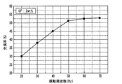
- FIG. 3 is a graph showing the relationship between the vibration frequency of the container and the filling rate of the hydrogen storage alloy when filling by vibration is performed.
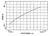
- FIG. 4 is a graph showing the relationship between the average particle size or powder size of the hydrogen storage alloy particles (alloy average particle size) and the filling rate of the hydrogen storage alloy when filling by vibration is performed.
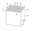
- FIG. 5 is a view showing an example of a container to which another embodiment of the present invention is applied.
- FIG. 5 is a view showing an example of a container to which another embodiment of the present invention is applied.
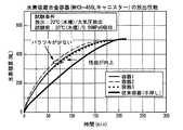
- FIG. 6 is a graph showing variation in the integrated hydrogen value in a plurality of filled containers obtained by the filling method according to one embodiment of the present invention.
- FIG. 7 is a graph showing variations in the integrated hydrogen value in a plurality of filled containers obtained by a conventional filling method.
- Embodiments of the present invention will be described in detail below, but the description of the constituent elements described below is an example (representative example) of an embodiment of the present invention, and the present invention does not exceed the gist thereof. It is not specified in the contents.
- “weight%” and “mass%” are synonymous.
- the container when filling a container with a hydrogen storage alloy made of a resin composite material by mixing hydrogen storage alloy particles or powder, resin, and carbon fiber, the container is vibrated at a predetermined frequency.
- the present invention relates to a hydrogen storage alloy filling method for adjusting the filling rate of the hydrogen storage alloy.
- the filling of the hydrogen storage alloy can be uniformly filled and the filling rate can be adjusted.
- the container is vibrated.
- filling and vibration may be performed alternately, or may be vibrated after filling, and vibration is applied while filling. (Filling and vibration may be performed simultaneously).
- vibration to the container while the container is filled with the hydrogen storage alloy as the resin composite material.
- filling can be performed more evenly and easily by applying vibration to the container during filling.
- giving vibration to the container during filling into the container means that filling and vibration are alternately performed or vibration is given while filling (filling and vibration are performed simultaneously).
- the target filling rate is set by the mixing ratio of the resin and the carbon fiber.
- the target filling rate of the hydrogen storage alloy can be set according to the mixing ratio of the resin and the carbon fiber.
- the filling rate is calculated by the volume ratio of the hydrogen storage alloy to the space in the container.
- the filling rate can be calculated by the following equation, for example.
- Filling rate (%) bulk specific gravity ⁇ true specific gravity of hydrogen storage alloy ⁇ 100 Bulk specific gravity: Bulk specific gravity of hydrogen storage alloy particles or powder (g / mL) -True specific gravity of hydrogen storage alloy: 8.1 (g / mL), for example
- the hydrogen storage alloy particles or powder have an average particle diameter or powder diameter (hereinafter sometimes simply referred to as an average particle diameter) of 1 to 1000 ⁇ m.
- an average particle diameter 1 to 1000 ⁇ m.
- the lower limit of the average particle diameter is 50 ⁇ m
- the upper limit of the average particle diameter is 1000 ⁇ m.
- the particle size of the hydrogen storage alloy also affects the filling rate of the hydrogen storage alloy. In these respects, it is more desirable that the lower limit of the average particle diameter or the powder diameter is 400 ⁇ m and the upper limit is 800 ⁇ m.
- the average particle size of the hydrogen storage alloy particles or powder can be measured by laser diffraction particle size distribution measurement.
- the mixing ratio of the carbon fibers is in the range of 0.1 to 5.0 mass% with respect to the amount of the hydrogen storage alloy. According to the above, by mixing an appropriate amount of carbon fiber, the filling amount of the hydrogen storage alloy can be adjusted to an appropriate amount, and good hydrogen absorption / release characteristics can be easily obtained.
- the predetermined frequency is preferably 30 to 70 Hz.
- the vibration frequency is adjusted in accordance with the container shape, it is possible to fill the hydrogen storage alloy material more evenly by continuously applying an appropriate vibration to the hydrogen storage alloy material.
- a frequency of 30 Hz or more is required to make the filling rate of the hydrogen storage alloy 40% or more.
- the frequency is 30 Hz or more, the filling rate is increased and the performance is improved.
- the upper limit is preferably 70 Hz from the viewpoint of device cost.
- the filling rate of the hydrogen storage alloy container is about 50 to 53%, and the frequency is more preferably 40 to 60 Hz, and further preferably 50 to 60 Hz.
- the hydrogen storage alloy material can be more smoothly filled by the vibration in the vertical direction.
- the amount of vibration to be moved in the vertical direction is preferably within a range of 0.1 to 2.0 mm.
- the hydrogen storage alloy is more evenly filled by appropriately determining the vibration amount of the container.
- the vertical vibration is preferably performed for 0.5 to 30 minutes.
- the hydrogen storage alloy material can be more evenly and reliably filled by vibration for an appropriate time.
- the vibration is applied for more than 30 minutes, the effect of improving the filling rate is saturated.
- the viscosity of the resin at 25 ° C. is preferably 500 to 10,000 mPa ⁇ s. According to the above, by making the viscosity of the resin appropriate, the filling of the hydrogen storage alloy becomes easy, and a more uniform alloy filling becomes possible.
- the viscosity can be measured by a predetermined method using a B-type rotational viscometer.
- the resin is preferably a gel-like resin having a consistency of 10 to 200 at 25 ° C.
- the 1/4 consistency is measured according to JIS K2220 (2013), and the material to be measured is an extremely soft material such as grease.
- the mixing amount of the resin is preferably 1 to 50% by mass with respect to the amount of the hydrogen storage alloy.
- the target filling rate of the hydrogen storage alloy is desirably 40 to 55%. According to the above, by making the filling rate of the hydrogen storage alloy appropriate, the hydrogen absorption / desorption characteristics become better, and the strain amount with respect to the container also falls within an appropriate range. By setting the filling rate to 40% or more, the absorption / release characteristics can be obtained more sufficiently. On the other hand, when the filling rate is 55% or less, the distortion to the container due to the expansion of the hydrogen storage alloy is small, which is preferable.
- the container has a cylinder shape and has a relatively small opening diameter with respect to the cylinder diameter. According to the above, the hydrogen storage alloy can be accommodated in a compact manner, the connection screw size can be reduced by reducing the diameter of the opening, and the sealing performance is further improved.
- a funnel is disposed in the opening of the container, the hydrogen storage alloy as the resin composite material is filled into the container through the funnel, and a scraping bar extending downward from the center of the funnel is provided. It is desirable to arrange.
- a funnel is used especially when filling a cylinder-type container with a small container mouth.
- the hydrogen storage alloy material used as a resin composite material is viscous, so it is immediately clogged even if vibration is applied manually. It may be difficult to fill the alloy.
- the hydrogen storage alloy can be more smoothly filled with the scraping bar.
- the hydrogen storage alloy can be filled more smoothly by moving the scraping bar up and down or / and rotating relative to the stopped or vibrating container.
- the hydrogen storage alloy of the present invention those having a composition of AB 5 , AB 2 , AB, A 2 B structure or BCC structure can be used.
- the type, composition, crystal structure and the like of the hydrogen storage alloy are not limited to specific ones.
- the hydrogen storage alloy particles preferably have an average particle diameter or powder diameter of 1 ⁇ m to 1000 ⁇ m.
- an appropriate method such as an atomizing method can be employed.
- FIG. 4 shows the relationship between the average particle size and filling rate of the hydrogen storage alloy.
- the filling rate decreases, and when the particle size is coarse (large), the filling rate tends to increase. For this reason, from the viewpoint of suppressing variation in the filling rate, it is more preferable to make the alloy grain sizes uniform in the range of 400 to 800 ⁇ m as the average grain size.
- the hydrogen storage alloy particles or powder is preferably mixed with a gel resin having a viscosity of 500 to 10,000 mPa ⁇ s at 25 ° C. and a consistency of 10 to 200 at 25 ° C.
- a gel resin having a viscosity of 500 to 10,000 mPa ⁇ s at 25 ° C. and a consistency of 10 to 200 at 25 ° C.
- the gel-like resin can be obtained by gelling a crosslinkable monomer or polymer including silicone, acrylic monomer or polymer, urethane or epoxy resin.
- silicone is preferably used because it is easy to handle, is permeable to hydrogen gas, and is easy to control gelation.
- Silicone is a liquid organopolysiloxane and generally used is represented by the formula (RR′SiO) n (R and R ′ are organic substituents, and n is a natural number).
- any one of an alkyl group such as a methyl group and an ethyl group, a phenyl group, and a fluoroalkyl group can be used independently. It may have a functional group such as a group.
- the mixing amount of the resin can be determined in an amount of 1 to 50% by mass with respect to the hydrogen storage alloy. As the resin, a soft resin is desirable, and a more appropriate resin viscosity can be maintained even in the expansion of the alloy.
- carbon fibers are mixed with the hydrogen storage alloy particles or powder. Carbon fiber can improve heat transfer and adjust the filling rate of the hydrogen storage alloy. As the carbon fiber, it is preferable to use a needle-like heat conductive carbon fiber material having a diameter or width of 1 to 1000 ⁇ m and an aspect ratio of 5 or more.
- This carbon fiber can be mixed together when the above resin is added and mixed.
- the addition amount is preferably 0.1 to 5.0 mass% with respect to the hydrogen storage alloy amount.
- Fig. 2 shows vibration when the amount of carbon fiber added to a hydrogen storage alloy with an average particle size of 100 to 600 ⁇ m (acicular carbon fiber with a diameter of 10 ⁇ m, a length of 6 mm and an aspect ratio of 600) is changed. The relationship in which the filling rate of the hydrogen storage alloy made into the resin composite material which gave the vibration on the conditions of frequency 60Hz, vibration amount 1.6mm, and 5 minutes changes is shown.
- the silicone resin used in this case is A liquid and B liquid of WACKER SilGel612 (manufactured by Asahi Kasei Wacker Silicone Co., Ltd.).
- the consistency is 85 and the mixing amount is 3.5% by mass.
- the vibration frequency is adjusted in order to adjust the filling rate of the hydrogen storage alloy.
- the time for applying vibration to the container is not limited to a specific range in the present invention, but is preferably 0.5 to 30 minutes. Further, at the time of vibration, it is preferable that the container is vibrated at least in the vertical direction, and the vibration amount is within a range of 0.1 to 2.0 mm in the vertical direction. In addition, in vibration, you may make it add horizontal vibration and rotational vibration in addition to the up-down direction, or at different times.
- FIG. 3 shows the relationship of the filling rate of the hydrogen storage alloy that becomes the resin composite when the vibration frequency is changed. By changing the vibration frequency in this way, the filling rate changes, and the filling rate can be easily adjusted.
- the filling rate of the hydrogen storage alloy as a resin composite changes when vibration is applied to a hydrogen storage alloy with an average particle size of 300 to 800 ⁇ m at a vibration frequency of 1.6 mm for 5 minutes. The relationship is shown in FIG.
- the hydrogen storage alloy contains 2% by mass of acicular carbon fiber having a diameter of 10 ⁇ m, a length of 6 mm and an aspect ratio of 600, and the silicone resin used is WACKER SilGel 612 solution A and B Liquid (manufactured by Asahi Kasei Wacker Silicone Co., Ltd.), the liquid viscosity is 1,000 mPa ⁇ s at 25 ° C., the 1/4 consistency at 25 ° C. of the gel resin is 85, and the mixing amount is 3.5 mass%.
- the target filling rate of the hydrogen storage alloy is 40 to 55% after vibration.
- the vibration base 10 has a vibrator plate 11 that is held so as to be able to vibrate.
- the vibrator plate 11 is installed on vibration motors 12A and 12B installed in parallel.
- the vibration mechanism is not particularly limited, and a configuration can be adopted as appropriate.
- a container holder 13 On the vibrator plate 11, a container holder 13 is provided, and the container 20 that holds the hydrogen storage alloy is held in the container holder 13.
- the container 20 has a cylinder shape, and an opening 21 having an inner diameter smaller than the inner diameter of the cylinder is provided at one end.
- the shape of the container is not particularly limited.
- a funnel 15 for inserting the tubular portion into the opening 21 of the container 20 is disposed, and the resin composite material is accommodated in the funnel 15. Further, a scraping bar 18 is disposed on the central axis of the funnel 15 so as to reach the tubular portion of the funnel 15.
- the above-described hydrogen storage alloy particles or powder, resin, and carbon fiber are added in advance as an alloy filling preparation, and mixed and stirred to prepare the resin composite 30.
- the container 20 is held by the container holder 13, the funnel 15 is installed in the opening 21, and the scraping bar 18 is disposed in the center of the funnel 15.
- the resin composite material 30 is supplied into the conical portion of the funnel 15, and the resin composite material 30 is filled into the container 20 while moving the scraping bar 18 up and down.
- the two vibration motors 12 ⁇ / b> A and 12 ⁇ / b> B are rotated in opposite directions, respectively, and a linear vibration of about 1.6 mm at maximum is preferably applied to the container 20 in the vertical direction.
- the inverter plate (vibrator plate) 11 applies vibration to the container at a vibration frequency of 30 to 70 Hz.
- the scraping bar 18 may be rotated in addition to the vertical movement.
- the operation of the scraping bar 18 may be performed either manually or by operation of a mechanical device. By the above operation, the resin composite material 30 is evenly filled in the container 20 without clogging the funnel 15.
- FIG. 5 shows another container example to which the present embodiment is applied.
- the container 40 has an aluminum square tube shape, and has edge wall portions 43 and 44 on both sides, and an intermediate wall portion 45 located in the middle thereof.
- the edge wall portions 43 and 44 and the intermediate wall portion 45 are each provided with a medium flow path (not shown), and the medium flow path includes a liquid inlet portion 41 and a liquid outlet portion 42 provided on the other side wall portion.
- the space between the edge wall portion 43 and the intermediate wall portion 45 and the space between the edge wall portion 44 and the intermediate wall portion 45 are brazed to the edge wall portions 43 and 44 and the intermediate wall portion 45, respectively.
- Corrugated fins 46 are arranged along the vertical direction of the wall portion. In each of the spaces, the resin composite material 50 is accommodated at an appropriate filling rate by the filling method of the present embodiment. As described above, in the present embodiment, the vibration filling of the resin composite material is possible regardless of the container shape.
- Example> An aluminum cylinder having an internal volume of 800 mL and an opening inner diameter of 14 mm was prepared. Further, AB 5 type alloy having an average particle size of about 700 ⁇ m, a gel-like silicone resin having a viscosity of 1,000 mPa ⁇ s and a quarter consistency at 85 ° C. of 85% by mass and a diameter of 10 ⁇ m 2 mass% of needle-like carbon fibers having a length of 6 mm and an aspect ratio of 600 were prepared, and these were mixed and stirred to obtain a resin composite material. Using the apparatus shown in FIG. 1, the resin composite material is vibrated under the conditions of a target filling rate of 52%, a vibration frequency of 50 Hz, an amplitude of 1.6 mm, and a vibration time of 5 minutes. Filled.
- a plurality of lots according to the above-mentioned examples and comparative examples were prepared, and hydrogen absorption / release characteristics tests were performed on each of the lots.
- hydrogen absorption of 0.99 MPaG was performed in a 20 ° C. water tank when fully filled, and the integrated value of hydrogen release was measured by releasing atmospheric pressure in the 20 ° C. water tank.
- the results are shown in the graphs of FIGS. 6 and 7, respectively. 6 and 7, the elapsed time is shown on the horizontal axis, and the integrated value of the hydrogen release amount is shown on the vertical axis.
- the hydrogen release characteristics in each lot were superior to those of conventional containers, and the variation was small.
- the average release characteristic was lower than that of the present example, and the variation was large.
Landscapes
- Chemical & Material Sciences (AREA)
- Engineering & Computer Science (AREA)
- Organic Chemistry (AREA)
- Chemical Kinetics & Catalysis (AREA)
- Combustion & Propulsion (AREA)
- Inorganic Chemistry (AREA)
- Mechanical Engineering (AREA)
- General Engineering & Computer Science (AREA)
- Filling Or Discharging Of Gas Storage Vessels (AREA)
- Powder Metallurgy (AREA)
- Hydrogen, Water And Hydrids (AREA)
Abstract
本発明は水素吸蔵合金を充填する際に、均一かつ容易に充填することを可能にすることを目的とする。本発明は水素吸蔵合金粒子または粉末と、樹脂と、カーボンファイバーとを混合して樹脂複合材とした水素吸蔵合金を容器内に充填する際に、前記容器を所定周波数で振動させて前記容器内の水素吸蔵合金の充填率を調整する水素吸蔵合金の充填方法に関する。
Description
この発明は、水素吸蔵合金粒子または粉末と、樹脂と、カーボンファイバーとを混合して樹脂複合材とした水素吸蔵合金を容器内に充填する方法に関するものである。
水素吸蔵合金は、水素吸蔵合金用容器に収容して水素ガスの吸収・放出を行っている。しかし、水素ガスの吸収・放出に伴って水素吸蔵合金自体が最大30%膨張、収縮するため、その際に生じる応力が水素吸蔵合金用容器にひずみを与え、容器変形が起こり極端なものは容器に亀裂が起こる場合もある。この合金膨張により起こる応力を緩和して容器ひずみを抑える方法として、水素吸蔵合金に樹脂とカーボンファイバーを混合して樹脂複合材とした水素吸蔵合金材料を水素吸蔵合金用容器に収納する方法がある。
一般的な水素吸蔵合金粉末はサラサラした状態となるが、上記樹脂の粘度が500~10,000mPa・sで、ちょう度を有するゲル状の樹脂とカーボンファイバーを適量添加混合したものでは、樹脂複合材に含まれる水素吸蔵合金の性状は湿った砂状のような水素吸蔵合金となるため、圧力容器として容器の口(開口部)が小さいシリンダータイプの水素吸蔵合金容器には合金充填が困難となる。
一般的な水素吸蔵合金粉末はサラサラした状態となるが、上記樹脂の粘度が500~10,000mPa・sで、ちょう度を有するゲル状の樹脂とカーボンファイバーを適量添加混合したものでは、樹脂複合材に含まれる水素吸蔵合金の性状は湿った砂状のような水素吸蔵合金となるため、圧力容器として容器の口(開口部)が小さいシリンダータイプの水素吸蔵合金容器には合金充填が困難となる。
従来の水素吸蔵合金の容器内への合金充填方法は、作業者が手作業で行うことが一般的である。水素吸蔵合金の充填方法を効率的に、かつ生産性を良くする方法として、特許文献1、特許文献2に示す技術が開示されている。
特許文献1では、水素吸蔵合金紛体を流体中に分散させ反応容器内に注入し、後から流体成分を取り除く方法が開示されている。特許文献2では、エアーカーテンで仕切られた小部屋を不活性ガスで置換し、ベルトコンベアーで水素吸蔵合金用容器を移送しながら、充填室内の汚染を最小限にして合金を連続的に充填する方法が開示されている。また、特許文献2には、水素吸蔵合金用容器に振動を加えることで内部構造に拘わらず隅々まで充填できる技術が記載されている。
特許文献1では、水素吸蔵合金紛体を流体中に分散させ反応容器内に注入し、後から流体成分を取り除く方法が開示されている。特許文献2では、エアーカーテンで仕切られた小部屋を不活性ガスで置換し、ベルトコンベアーで水素吸蔵合金用容器を移送しながら、充填室内の汚染を最小限にして合金を連続的に充填する方法が開示されている。また、特許文献2には、水素吸蔵合金用容器に振動を加えることで内部構造に拘わらず隅々まで充填できる技術が記載されている。
しかし、従来技術の水素吸蔵合金充填方法は、水素吸蔵合金粒子または粉末と樹脂とカーボンファイバーとを混合して樹脂複合材とした水素吸蔵合金を充填する際には適用できない。
特許文献1に記載の方法では、せっかく水素吸蔵合金が樹脂で一様に覆われているのに、流動するための流体を後工程で除去する時に当該樹脂が取れてしまい、応力を緩和する樹脂の効果がなくなってしまう。
特許文献1に記載の方法では、せっかく水素吸蔵合金が樹脂で一様に覆われているのに、流動するための流体を後工程で除去する時に当該樹脂が取れてしまい、応力を緩和する樹脂の効果がなくなってしまう。
また、特許文献2では、ベルトコンベアーで連続的に水素吸蔵合金容器に充填する方法が開示されており、使用する水素吸蔵合金は粘性のない粉末状の水素吸蔵合金である。このため、樹脂とカーボンファイバーを混合した樹脂複合材となる水素吸蔵合金材料の充填率の調整には適用できない。特許文献2の振動等は内部構造の隅々にまで材料を充填するために行われるものであり、振動、回転を容器に与える場合も、充填がなされた後に行われており、特に容器の口が小さいシリンダータイプの容器には、このような樹脂複合材となる水素吸蔵合金材料は、粘性があるため単純な振動のみを用いた充填方法では適用することはできない。
このような水素吸蔵合金粒子(または粉末)と樹脂とカーボンファイバーとを混合した樹脂複合材は、充填の自動化が難しく、前記したように一般的には手作業で充填が行われている。また、水素吸蔵合金は、容器内に充填したままで力を加えないと充填率が低すぎて性能がでない。逆に押し込みすぎると充填率が上がりすぎて、内部に圧損が付き吸収および放出性能に影響がでる。このため適切な充填率になるように樹脂複合材となる水素吸蔵合金にカーボンファイバーを添加混合して、適度な力加減で押し込むことで充填率を調整している。しかし、一般的にこの押し込む作業は手作業となるため、合金充填密度が粗密となり、ロットによって、水素の放出性能にバラツキが生じる。また、この作業は非常に時間と手間もかかり、効率上不十分であった。
この発明は上記事情を背景としてなされたものであり、合金充填密度の粗密や、水素放出性能のバラツキ、合金充填作業の困難性などの課題を解決するためになされたもので、水素吸蔵合金粒子(または粉末)と樹脂とカーボンファイバーを混合して樹脂複合材とした水素吸蔵合金を容器内に、容易に充填を可能とし、また充填率も均一に調整が可能な充填方法を提供することを目的としている。
本発明者らが鋭意検討した結果、水素吸蔵合金粒子または粉末と、樹脂と、カーボンファイバーとを混合して樹脂複合材とした水素吸蔵合金を容器内に充填する際に、前記容器を所定周波数で振動させて容器内の水素吸蔵合金の充填率を調整することにより、上記課題を解決できることが分かり、本発明を完成するに至った。
すなわち、本発明の要旨は以下のとおりである。
<1>水素吸蔵合金粒子または粉末と、樹脂と、カーボンファイバーとを混合して樹脂複合材とした水素吸蔵合金を容器内に充填する際に、前記容器を所定周波数で振動させて前記容器内の水素吸蔵合金の充填率を調整する水素吸蔵合金の充填方法。
<2>前記水素吸蔵合金を前記容器へ充填する途中に、前記容器に振動を付与する前記<1>に記載の水素吸蔵合金の充填方法。
<3>目標とする前記充填率を前記樹脂と前記カーボンファイバーの混合率によって設定する前記<1>または<2>に記載の水素吸蔵合金の充填方法。
<4>前記水素吸蔵合金粒子または粉末の平均粒径が1~1000μmである前記<1>~<3>のいずれか1に記載の水素吸蔵合金の充填方法。
<5>前記カーボンファイバーの混合率を、水素吸蔵合金量に対し、0.1~5.0重量%とする前記<1>~<4>のいずれか1に記載の水素吸蔵合金の充填方法。
<6>前記所定周波数が、30~70Hzである前記<1>~<5>のいずれか1に記載の水素吸蔵合金の充填方法。
<7>前記容器を、少なくとも上下方向に移動させて振動させる前記<1>~<6>のいずれか1に記載の水素吸蔵合金の充填方法。
<8>前記上下方向に移動させる振動量が、0.1~2.0mmである前記<7>に記載の水素吸蔵合金の充填方法。
<9>前記容器を0.5~30分間振動させる前記<7>または<8>に記載の水素吸蔵合金の充填方法。
<10>前記樹脂の25℃における粘度が500~10,000mPa・sである前記<1>~<9>のいずれか1に記載の水素吸蔵合金の充填方法。
<11>前記樹脂が、25℃における1/4ちょう度10~200のゲル状樹脂である前記<1>~<10>のいずれか1に記載の水素吸蔵合金の充填方法。
<12>前記樹脂の混合量が、水素吸蔵合金量に対して1~50重量%で混合する前記<1>~<11>のいずれか1に記載の水素吸蔵合金の充填方法。
<13>前記水素吸蔵合金の目標充填率が40~55%である前記<1>~<12>のいずれか1に記載の水素吸蔵合金の充填方法。
<14>前記容器の開口部に漏斗を配置し、前記漏斗を通して前記容器内に前記樹脂複合材とした前記水素吸蔵合金を充填するとともに、前記漏斗の中央部から下方に伸びた掻き出し棒を配置する前記<1>~<13>のいずれか1に記載の水素吸蔵合金の充填方法。
すなわち、本発明の要旨は以下のとおりである。
<1>水素吸蔵合金粒子または粉末と、樹脂と、カーボンファイバーとを混合して樹脂複合材とした水素吸蔵合金を容器内に充填する際に、前記容器を所定周波数で振動させて前記容器内の水素吸蔵合金の充填率を調整する水素吸蔵合金の充填方法。
<2>前記水素吸蔵合金を前記容器へ充填する途中に、前記容器に振動を付与する前記<1>に記載の水素吸蔵合金の充填方法。
<3>目標とする前記充填率を前記樹脂と前記カーボンファイバーの混合率によって設定する前記<1>または<2>に記載の水素吸蔵合金の充填方法。
<4>前記水素吸蔵合金粒子または粉末の平均粒径が1~1000μmである前記<1>~<3>のいずれか1に記載の水素吸蔵合金の充填方法。
<5>前記カーボンファイバーの混合率を、水素吸蔵合金量に対し、0.1~5.0重量%とする前記<1>~<4>のいずれか1に記載の水素吸蔵合金の充填方法。
<6>前記所定周波数が、30~70Hzである前記<1>~<5>のいずれか1に記載の水素吸蔵合金の充填方法。
<7>前記容器を、少なくとも上下方向に移動させて振動させる前記<1>~<6>のいずれか1に記載の水素吸蔵合金の充填方法。
<8>前記上下方向に移動させる振動量が、0.1~2.0mmである前記<7>に記載の水素吸蔵合金の充填方法。
<9>前記容器を0.5~30分間振動させる前記<7>または<8>に記載の水素吸蔵合金の充填方法。
<10>前記樹脂の25℃における粘度が500~10,000mPa・sである前記<1>~<9>のいずれか1に記載の水素吸蔵合金の充填方法。
<11>前記樹脂が、25℃における1/4ちょう度10~200のゲル状樹脂である前記<1>~<10>のいずれか1に記載の水素吸蔵合金の充填方法。
<12>前記樹脂の混合量が、水素吸蔵合金量に対して1~50重量%で混合する前記<1>~<11>のいずれか1に記載の水素吸蔵合金の充填方法。
<13>前記水素吸蔵合金の目標充填率が40~55%である前記<1>~<12>のいずれか1に記載の水素吸蔵合金の充填方法。
<14>前記容器の開口部に漏斗を配置し、前記漏斗を通して前記容器内に前記樹脂複合材とした前記水素吸蔵合金を充填するとともに、前記漏斗の中央部から下方に伸びた掻き出し棒を配置する前記<1>~<13>のいずれか1に記載の水素吸蔵合金の充填方法。
本発明によれば、水素吸蔵合金粒子または粉末と樹脂とカーボンファイバーとを混合して樹脂複合材とした水素吸蔵合金を容器内に所望の充填率で充填することができる。また、充填率を均一に調整して充填することができることで、容器内の圧損を低く抑えられ水素放出性能のバラツキが小さくなり放出速度も向上できる。更に、合金充填作業時間を大幅に短縮できる効果がある。
以下に本発明の実施の形態を詳細に説明するが、以下に記載する構成要件の説明は、本発明の実施態様の一例(代表例)であり、本発明はその要旨を超えない限り、これらの内容に特定されない。ここで、“重量%”と“質量%”とは同義である。
本発明は水素吸蔵合金粒子または粉末と、樹脂と、カーボンファイバーとを混合して樹脂複合材とした水素吸蔵合金を容器内に充填する際に、前記容器を所定周波数で振動させて前記容器内の水素吸蔵合金の充填率を調整する水素吸蔵合金の充填方法に関する。
上記によれば、充填の際に容器に所定周波数の振動を継続的に与えることで、水素吸蔵合金の充填を均一に充填し、充填率を調整することができる。ここで、水素吸蔵合金を容器内に充填する際に前記容器を振動させるとは、充填と振動を交互に行ってもよいし、充填後に振動させてもよく、また、充填しながら振動を付与して(充填と振動を同時に行って)もよい。
本発明は水素吸蔵合金粒子または粉末と、樹脂と、カーボンファイバーとを混合して樹脂複合材とした水素吸蔵合金を容器内に充填する際に、前記容器を所定周波数で振動させて前記容器内の水素吸蔵合金の充填率を調整する水素吸蔵合金の充填方法に関する。
上記によれば、充填の際に容器に所定周波数の振動を継続的に与えることで、水素吸蔵合金の充填を均一に充填し、充填率を調整することができる。ここで、水素吸蔵合金を容器内に充填する際に前記容器を振動させるとは、充填と振動を交互に行ってもよいし、充填後に振動させてもよく、また、充填しながら振動を付与して(充填と振動を同時に行って)もよい。
本発明において、前記樹脂複合材として前記水素吸蔵合金を前記容器内へ充填する途中に、前記容器に振動を付与することが望ましい。
上記によれば、充填中に容器に振動を与えることで充填をより均等かつ容易に行うことができる。ここで、前記容器内へ充填する途中に前記容器に振動を付与するとは、充填と振動を交互に行う、または、充填しながら振動を付与する(充填と振動を同時に行う)ことを意味する。
上記によれば、充填中に容器に振動を与えることで充填をより均等かつ容易に行うことができる。ここで、前記容器内へ充填する途中に前記容器に振動を付与するとは、充填と振動を交互に行う、または、充填しながら振動を付与する(充填と振動を同時に行う)ことを意味する。
本発明において、目標とする前記充填率を前記樹脂と前記カーボンファイバーの混合率によって設定することが望ましい。
上記によれば、樹脂とカーボンファイバーの混合率に従って目標とする水素吸蔵合金の充填率を設定することができる。カーボンファイバーと水素吸蔵合金の充填量との間には、相関関係が認められる。充填率は、容器内空間に対する水素吸蔵合金の体積比によって算出される。
なお、充填率は、例えば以下の式によって算出することができる。
充填率(%)=嵩比重÷水素吸蔵合金の真比重×100
・嵩比重:水素吸蔵合金粒子または粉末の嵩比重(g/mL)
・水素吸蔵合金の真比重:例えば8.1(g/mL)
上記によれば、樹脂とカーボンファイバーの混合率に従って目標とする水素吸蔵合金の充填率を設定することができる。カーボンファイバーと水素吸蔵合金の充填量との間には、相関関係が認められる。充填率は、容器内空間に対する水素吸蔵合金の体積比によって算出される。
なお、充填率は、例えば以下の式によって算出することができる。
充填率(%)=嵩比重÷水素吸蔵合金の真比重×100
・嵩比重:水素吸蔵合金粒子または粉末の嵩比重(g/mL)
・水素吸蔵合金の真比重:例えば8.1(g/mL)
本発明において、水素吸蔵合金粒子または粉末の平均粒径または粉末径(以下、単に平均粒径と称することがある。)が1~1000μmであることが望ましい。
上記によれば、より適正な水素吸放出特性が得られるとともに、充填率を適正範囲により容易に調整することができる。なお、より望ましくは、平均粒径の下限を50μm、平均粒径の上限を1000μmとすることが望ましい。また、水素吸蔵合金の粒径は、水素吸蔵合金の充填率にも影響を与える。これらの点でさらに平均粒径または粉末径の下限を400μm、上限を800μmとすることが一層望ましい。
水素吸蔵合金粒子または粉末の平均粒径はレーザー回折式粒度分布測定によって測定することができる。
上記によれば、より適正な水素吸放出特性が得られるとともに、充填率を適正範囲により容易に調整することができる。なお、より望ましくは、平均粒径の下限を50μm、平均粒径の上限を1000μmとすることが望ましい。また、水素吸蔵合金の粒径は、水素吸蔵合金の充填率にも影響を与える。これらの点でさらに平均粒径または粉末径の下限を400μm、上限を800μmとすることが一層望ましい。
水素吸蔵合金粒子または粉末の平均粒径はレーザー回折式粒度分布測定によって測定することができる。
本発明において、前記カーボンファイバーの混合率を、水素吸蔵合金量に対し、0.1~5.0質量%の範囲内とすることが望ましい。
上記によれば、適量のカーボンファイバーを混合することで、水素吸蔵合金の充填量を適切量に調整することができ、また、良好な水素吸放出特性が得られやすい。
上記によれば、適量のカーボンファイバーを混合することで、水素吸蔵合金の充填量を適切量に調整することができ、また、良好な水素吸放出特性が得られやすい。
本発明において、前記所定周波数が、30~70Hzであることが望ましい。
容器形状に合わせて振動周波数を調整して行うが、水素吸蔵合金材料に適当な振動を継続して与えることで、水素吸蔵合金材料をより均等に充填することが可能になる。
例えば、水素吸蔵合金の充填率を40%以上とするには周波数30Hz以上が必要となる。周波数が30Hz以上とすることで充填率が上がり性能が向上する。一方、70Hzを超えると水素吸蔵合金の充填率は上がらず、60Hz以上で飽和する。また、装置コストの関係上、上限は70Hzが望ましい。通常、水素吸蔵合金容器への充填率は50~53%程度としており、周波数は40~60Hzがより望ましく、50~60Hzが一層望ましい。
容器形状に合わせて振動周波数を調整して行うが、水素吸蔵合金材料に適当な振動を継続して与えることで、水素吸蔵合金材料をより均等に充填することが可能になる。
例えば、水素吸蔵合金の充填率を40%以上とするには周波数30Hz以上が必要となる。周波数が30Hz以上とすることで充填率が上がり性能が向上する。一方、70Hzを超えると水素吸蔵合金の充填率は上がらず、60Hz以上で飽和する。また、装置コストの関係上、上限は70Hzが望ましい。通常、水素吸蔵合金容器への充填率は50~53%程度としており、周波数は40~60Hzがより望ましく、50~60Hzが一層望ましい。
本発明において、前記容器を少なくとも上下方向に移動させて振動させることが望ましい。
上記によれば、上下方向への振動によって水素吸蔵合金材料の充填がより円滑になされる。
上記によれば、上下方向への振動によって水素吸蔵合金材料の充填がより円滑になされる。
本発明において、前記上下方向に移動させる振動量が、0.1~2.0mmの範囲内であることが望ましい。
上記によれば、容器の振動量を適切に定めることで水素吸蔵合金の充填がより均等になされる。振動量を0.1mm以上とすることで振動による効果をより十分に得ることができ、2.0mm以下とすることで樹脂複合材の合金粉末が大きく跳ね上がり、ジョウロなどから合金がこぼれてしまうことを防ぐことができる。
上記によれば、容器の振動量を適切に定めることで水素吸蔵合金の充填がより均等になされる。振動量を0.1mm以上とすることで振動による効果をより十分に得ることができ、2.0mm以下とすることで樹脂複合材の合金粉末が大きく跳ね上がり、ジョウロなどから合金がこぼれてしまうことを防ぐことができる。
本発明において、前記上下方向の振動を0.5~30分間行うことが望ましい。
上記によれば、適当な時間の振動によって水素吸蔵合金材料の充填をより均等かつ確実におこなうことができる。一方、30分を超えて振動を与えても、充填率の向上効果は飽和する。
上記によれば、適当な時間の振動によって水素吸蔵合金材料の充填をより均等かつ確実におこなうことができる。一方、30分を超えて振動を与えても、充填率の向上効果は飽和する。
本発明において、前記樹脂の25℃における粘度が500~10,000mPa・sであることが望ましい。
上記によれば、樹脂の粘度を適正にすることで、水素吸蔵合金の充填が容易になり、より均一な合金充填が可能となる。
上記粘度は、B型回転粘度計によって、定められた方法で測定することができる。
上記によれば、樹脂の粘度を適正にすることで、水素吸蔵合金の充填が容易になり、より均一な合金充填が可能となる。
上記粘度は、B型回転粘度計によって、定められた方法で測定することができる。
本発明において、前記樹脂が25℃における1/4ちょう度10~200のゲル状樹脂であることが望ましい。
ここで1/4ちょう度とはJIS K2220(2013年)に従って測定され、測定の対象となる物質はグリース等の極めて柔らかい物質である。
ここで1/4ちょう度とはJIS K2220(2013年)に従って測定され、測定の対象となる物質はグリース等の極めて柔らかい物質である。
本発明において、前記樹脂の混合量は水素吸蔵合金量に対して1~50質量%とすることが好ましい。
樹脂の混合量を適量にすることで、水素吸蔵合金充填率を適切量に調整でき、さらに水素吸蔵合金材料全体の柔らかさをより適切に調整することができる。
樹脂の混合量を適量にすることで、水素吸蔵合金充填率を適切量に調整でき、さらに水素吸蔵合金材料全体の柔らかさをより適切に調整することができる。
本発明において、水素吸蔵合金の目標充填率が40~55%であることが望ましい。
上記によれば、水素吸蔵合金の充填率を適正にすることで水素の吸放出特性がより良好になり、容器に対する歪み量もより適正な範囲内になる。充填率を40%以上とすることで吸放出特性をより十分に得ることができる。一方、充填率を55%以下とすることで水素吸蔵合金の膨張による容器への歪みが小さく、より好ましい。
上記によれば、水素吸蔵合金の充填率を適正にすることで水素の吸放出特性がより良好になり、容器に対する歪み量もより適正な範囲内になる。充填率を40%以上とすることで吸放出特性をより十分に得ることができる。一方、充填率を55%以下とすることで水素吸蔵合金の膨張による容器への歪みが小さく、より好ましい。
本発明において、前記容器がシリンダー形状を有し、シリンダー径に対し、相対的に小さい開口部の口径を有するものを使用することが好ましい。
上記によれば、水素吸蔵合金をコンパクトに収容できるとともに、開口部の口径を小さくすることで接続ネジサイズを小さくでき、シール性も一層向上される。
上記によれば、水素吸蔵合金をコンパクトに収容できるとともに、開口部の口径を小さくすることで接続ネジサイズを小さくでき、シール性も一層向上される。
本発明において、前記容器の開口部に漏斗を配置し、前記漏斗を通して前記容器内に前記樹脂複合材とした前記水素吸蔵合金を充填するとともに、前記漏斗の中央部から下方に伸びた掻き出し棒を配置することが望ましい。
従来の方法では、特に容器の口が小さいシリンダータイプの容器に充填する場合、漏斗を使用するが、樹脂複合材となる水素吸蔵合金材料に粘性があるため手作業で振動を与えてもすぐ詰まってしまい合金を充填しにくい場合がある。上記構成によれば、掻き出し棒によって水素吸蔵合金の充填をより円滑に行うことができる。また、停止中または振動中の容器に対し掻き出し棒を上下移動または/および回転移動させることで水素吸蔵合金の充填をより円滑に行うことが可能になる。
従来の方法では、特に容器の口が小さいシリンダータイプの容器に充填する場合、漏斗を使用するが、樹脂複合材となる水素吸蔵合金材料に粘性があるため手作業で振動を与えてもすぐ詰まってしまい合金を充填しにくい場合がある。上記構成によれば、掻き出し棒によって水素吸蔵合金の充填をより円滑に行うことができる。また、停止中または振動中の容器に対し掻き出し棒を上下移動または/および回転移動させることで水素吸蔵合金の充填をより円滑に行うことが可能になる。
本発明の一実施形態を添付図面に基づいて説明する。
本発明の水素吸蔵合金としては、AB5、AB2、AB、A2B構造やBCC構造の組成のものを用いることができる。なお、本発明としては水素吸蔵合金の種別、組成、結晶構造などが特定のものに限定されるものではない。また、水素吸蔵合金粒は、好適には平均粒径または粉末径を1μm~1000μmとする。水素吸蔵合金の粒子化、粉末化の方法も特に限定されるものではなく、アトマイズ法などの適宜の方法を採用することができる。
図4に水素吸蔵合金の平均粒度と充填率の関係を示す。合金粒度が細かい(小さい)と充填率は減少し、粒度が粗い(大きい)と充填率は高くなる傾向にある。このため充填率のバラツキを抑える観点から、平均粒径として400~800μmとする範囲で合金粒度を揃えた方がさらに好ましい。
本発明の水素吸蔵合金としては、AB5、AB2、AB、A2B構造やBCC構造の組成のものを用いることができる。なお、本発明としては水素吸蔵合金の種別、組成、結晶構造などが特定のものに限定されるものではない。また、水素吸蔵合金粒は、好適には平均粒径または粉末径を1μm~1000μmとする。水素吸蔵合金の粒子化、粉末化の方法も特に限定されるものではなく、アトマイズ法などの適宜の方法を採用することができる。
図4に水素吸蔵合金の平均粒度と充填率の関係を示す。合金粒度が細かい(小さい)と充填率は減少し、粒度が粗い(大きい)と充填率は高くなる傾向にある。このため充填率のバラツキを抑える観点から、平均粒径として400~800μmとする範囲で合金粒度を揃えた方がさらに好ましい。
水素吸蔵合金粒子または粉末には、好適には、25℃における粘度が500~10,000mPa・sで、25℃における1/4ちょう度10~200のゲル状樹脂が混合される。このような樹脂として、ゲル状樹脂は、シリコーン、アクリルモノマーやポリマー、ウレタン、エポキシ樹脂をはじめとする架橋性のモノマーやポリマーをゲル化させて得ることができる。中でもシリコーンは取り扱い性が容易で水素ガス透過性であり、ゲル化のコントロールも容易であることから好ましく用いることができる。
シリコーンとは液状のオルガノポリシロキサンであり、一般には式(RR’SiO)n(R、R’は有機置換基、nは自然数)で表されるものが使用される。R及びR’の具体例としては、それぞれ独立してメチル基、エチル基等のアルキル基、フェニル基、フルオロアルキル基のいずれかを用いることができ、分子鎖末端には水酸基、アルコキシ基、ビニル基等の官能基を有してもよい。樹脂の混合量としては、水素吸蔵合金に対し、1~50質量%の量で混合量を定めることができる。樹脂としては軟質樹脂が望ましく、合金膨張吸収においても、より適正な樹脂粘度を保つことができる。
シリコーンとは液状のオルガノポリシロキサンであり、一般には式(RR’SiO)n(R、R’は有機置換基、nは自然数)で表されるものが使用される。R及びR’の具体例としては、それぞれ独立してメチル基、エチル基等のアルキル基、フェニル基、フルオロアルキル基のいずれかを用いることができ、分子鎖末端には水酸基、アルコキシ基、ビニル基等の官能基を有してもよい。樹脂の混合量としては、水素吸蔵合金に対し、1~50質量%の量で混合量を定めることができる。樹脂としては軟質樹脂が望ましく、合金膨張吸収においても、より適正な樹脂粘度を保つことができる。
また、水素吸蔵合金粒子または粉末には、カーボンファイバーが混合される。カーボンファイバーは、伝熱性を高めるとともに水素吸蔵合金の充填率を調整することができる。カーボンファイバーは、直径または幅が1~1000μmでアスペクト比が5以上の針状の伝熱性炭素繊維材料を使用することが好ましい。
このカーボンファイバーは、上記樹脂を添加混合するときに合わせて混合することができる。添加量は水素吸蔵合金量に対して0.1~5.0質量%添加することが好ましい。
図2に、平均粒径が100~600μmの水素吸蔵合金に添加するカーボンファイバー量(直径が10μm、長さが6mmでアスペクト比が600の針状のカーボンファイバー)を変化させたときに、振動周波数60Hz、振動量1.6mm、5分間の条件で振動を与えた樹脂複合材とした水素吸蔵合金の充填率が変化する関係を示す。なお、この際に使用したシリコーン樹脂は、WACKER SilGel612のA液及びB液(旭化成ワッカーシリコーン株式会社製)、液粘度は25℃で1,000mPa・s、ゲル状樹脂の25℃における1/4ちょう度は85で、混合量は3.5質量%としている。
上記のようにカーボンファイバーの混合量を変えることで水素吸蔵合金の目標とする充填率が顕著に変わり、調整もより容易となる。
図2に、平均粒径が100~600μmの水素吸蔵合金に添加するカーボンファイバー量(直径が10μm、長さが6mmでアスペクト比が600の針状のカーボンファイバー)を変化させたときに、振動周波数60Hz、振動量1.6mm、5分間の条件で振動を与えた樹脂複合材とした水素吸蔵合金の充填率が変化する関係を示す。なお、この際に使用したシリコーン樹脂は、WACKER SilGel612のA液及びB液(旭化成ワッカーシリコーン株式会社製)、液粘度は25℃で1,000mPa・s、ゲル状樹脂の25℃における1/4ちょう度は85で、混合量は3.5質量%としている。
上記のようにカーボンファイバーの混合量を変えることで水素吸蔵合金の目標とする充填率が顕著に変わり、調整もより容易となる。
また、水素吸蔵合金の充填率を調整するため、振動周波数を調整して行う。
また、容器に振動を与える時間は本願発明としては特定の範囲に限定されるものではないが、0.5~30分が望ましい。
また、振動に際しては、容器に対して少なくとも上下方向に振動を与え、その振動量を上下方向で0.1~2.0mmの範囲内とすることが好ましい。なお、振動においては、上下方向以外に横方向の振動や回転振動を組み合わせて、または時期を異にして加えるようにしてもよい。
また、容器に振動を与える時間は本願発明としては特定の範囲に限定されるものではないが、0.5~30分が望ましい。
また、振動に際しては、容器に対して少なくとも上下方向に振動を与え、その振動量を上下方向で0.1~2.0mmの範囲内とすることが好ましい。なお、振動においては、上下方向以外に横方向の振動や回転振動を組み合わせて、または時期を異にして加えるようにしてもよい。
図3に振動周波数を変化させた時の樹脂複合材となる水素吸蔵合金の充填率の関係を示す。このように振動周波数を変えることで充填率が変わり、充填率の調整も容易となる。平均粒径が300~800μmの水素吸蔵合金に、振動周波数を変えて、振幅量1.6mm、5分間の条件で振動を与えた場合の、樹脂複合材とした水素吸蔵合金の充填率が変化する関係を図3に示す。なお、この際に、水素吸蔵合金に対し、直径が10μm、長さが6mmでアスペクト比が600の針状のカーボンファイバーを2質量%含有し、使用したシリコーン樹脂はWACKER SilGel612のA液及びB液(旭化成ワッカーシリコーン株式会社製)、液粘度は25℃で1,000mPa・s、ゲル状樹脂の25℃における1/4ちょう度は85で、混合量は3.5質量%としている。
樹脂複合材を容器に充填する際には、振動後において、水素吸蔵合金の目標充填率が40~55%になるように調整することが好ましい。
次に、容器に樹脂複合材を充填する際の装置を図1に基づいて説明する。
振動基台10は、振動可能に保持されたバイブレータ板11を有しており、該バイブレータ板11は並列設置された振動モータ12A、12B上に設置されている。なお、本発明としては振動の機構が特に限定されるものではなく、適宜構成を採用することができる。
振動基台10は、振動可能に保持されたバイブレータ板11を有しており、該バイブレータ板11は並列設置された振動モータ12A、12B上に設置されている。なお、本発明としては振動の機構が特に限定されるものではなく、適宜構成を採用することができる。
バイブレータ板11上では、容器保持具13が設けられており、容器保持具13に水素吸蔵合金を収容する容器20が保持される。この実施形態では、容器20はシリンダー形状を有し、一端にシリンダー内径よりも小径の内径を有する開口部21が設けられている。なお、本発明としては容器形状が特に限定されるものではない。
容器20上には、容器20の開口部21内に管状部を挿入する漏斗15が配置され、漏斗15内に樹脂複合材が収容される。また、漏斗15の中心軸には、漏斗15の管状部内に至るように掻き出し棒18が配置される。
容器20上には、容器20の開口部21内に管状部を挿入する漏斗15が配置され、漏斗15内に樹脂複合材が収容される。また、漏斗15の中心軸には、漏斗15の管状部内に至るように掻き出し棒18が配置される。
上記装置を用いた充填方法を説明する。
前記した水素吸蔵合金粒子または粉末、樹脂、カーボンファイバーを予め合金充填準備として、添加混合して撹拌し、樹脂複合材30を用意する。
容器20は、上記したように容器保持具13で保持し、開口部21に漏斗15を設置し、漏斗15内の中心に掻き出し棒18を配置する。
前記した水素吸蔵合金粒子または粉末、樹脂、カーボンファイバーを予め合金充填準備として、添加混合して撹拌し、樹脂複合材30を用意する。
容器20は、上記したように容器保持具13で保持し、開口部21に漏斗15を設置し、漏斗15内の中心に掻き出し棒18を配置する。
漏斗15の円錐部内に樹脂複合材30を供給し、掻き出し棒18を上下移動させつつ容器20内に樹脂複合材30を充填する。充填中には、2台の振動モータ12A、12Bを各々反対方向に回転させ、容器20に対して垂直方向に好ましくは最大1.6mm程度の直線振動を与える。その際には、インバーター板(バイブレータ板)11からは容器に対し、振動周波数30~70Hzで振動が与えられる。掻き出し棒18を上下方向19に運動させることで、漏斗15の円錐部に供給される樹脂複合材30が順次容器20内に収容される。なお、掻き出し棒18は、上下運動の他、回転運動させるものであってもよい。掻き出し棒18の操作は、手作業または機械装置の動作のどちらで行ってもよい。
上記動作によって、樹脂複合材30は、漏斗15に詰まることなく容器20内に均等に充填される。
上記動作によって、樹脂複合材30は、漏斗15に詰まることなく容器20内に均等に充填される。
なお、上記実施形態では、開口部の口径が小さい容器に対し、樹脂複合材を供給する例について説明したが、本発明としては、容器の形状が特に限定されるものではなく、開口部の口径が小さいものに限定されない。以下に、その例を説明する。
図5は、本実施形態が適用される他の容器例を示すものである。
容器40は、アルミニウム製の角筒形状からなり、両側の縁壁部43、44と、その中間に位置する中間壁部45とを有している。縁壁部43、44、中間壁部45には、それぞれ媒体流路(図示しない)が設けられており、媒体流路には、他側壁部に設けられた入液部41と出液部42とが接続されて媒体の流通が可能になっている。
縁壁部43と中間壁部45との間の空間と、縁壁部44と中間壁部45との間の空間には、縁壁部43、44と中間壁部45とに、それぞれろう付けされたコルゲートフィン46が壁部の縦方向に沿って配置されている。上記各空間には、本実施形態の充填方法によって樹脂複合材50が適度な充填率で収納されている。このように本実施形態では、容器形状に拘わらず樹脂複合材の加振充填が可能になる。
容器40は、アルミニウム製の角筒形状からなり、両側の縁壁部43、44と、その中間に位置する中間壁部45とを有している。縁壁部43、44、中間壁部45には、それぞれ媒体流路(図示しない)が設けられており、媒体流路には、他側壁部に設けられた入液部41と出液部42とが接続されて媒体の流通が可能になっている。
縁壁部43と中間壁部45との間の空間と、縁壁部44と中間壁部45との間の空間には、縁壁部43、44と中間壁部45とに、それぞれろう付けされたコルゲートフィン46が壁部の縦方向に沿って配置されている。上記各空間には、本実施形態の充填方法によって樹脂複合材50が適度な充填率で収納されている。このように本実施形態では、容器形状に拘わらず樹脂複合材の加振充填が可能になる。
以下に、本発明の実施例を比較例と対比しつつ説明する。
<実施例>
内容積800mLで開口部内径が14mmのアルミシリンダーを用意した。また、平均粒度が700μm程度のAB5系合金と、粘度が1,000mPa・sで、25℃における1/4ちょう度を85としたゲル状のシリコーン樹脂を3.5質量%、直径が10μm、長さが6mmでアスペクト比が600の針状のカーボンファイバーを2質量%用意し、これらを混合撹拌して樹脂複合材を得た。
上記樹脂複合材を図1に示す装置を用いて、目標充填率を52%にして、振動周波数50Hz、振幅1.6mm、振動時間5分の条件で振動を与えて、容器に樹脂複合材を充填した。
<実施例>
内容積800mLで開口部内径が14mmのアルミシリンダーを用意した。また、平均粒度が700μm程度のAB5系合金と、粘度が1,000mPa・sで、25℃における1/4ちょう度を85としたゲル状のシリコーン樹脂を3.5質量%、直径が10μm、長さが6mmでアスペクト比が600の針状のカーボンファイバーを2質量%用意し、これらを混合撹拌して樹脂複合材を得た。
上記樹脂複合材を図1に示す装置を用いて、目標充填率を52%にして、振動周波数50Hz、振幅1.6mm、振動時間5分の条件で振動を与えて、容器に樹脂複合材を充填した。
<比較例>
上記実施例と同じ樹脂複合材を上記と同じ容器に対し、従来の手作業(手押し)によって充填作業を行った。この際の作業は約1時間を要したことから、本実施例の作業効率は格段に優れていた。
上記実施例と同じ樹脂複合材を上記と同じ容器に対し、従来の手作業(手押し)によって充填作業を行った。この際の作業は約1時間を要したことから、本実施例の作業効率は格段に優れていた。
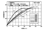
上記実施例および比較例による複数のロットを用意し、それぞれについて水素の吸放出特性試験を行った。試験では、20℃水槽中で、満充填で0.99MPaGの水素吸収を行い、20℃水槽中で大気圧放出によって水素放出の積算値を測定した。その結果をそれぞれ図6及び図7のグラフに示した。図6及び図7では、横軸に経過時間、縦軸に水素放出量の積算値を示した。
実施例では、各ロットにおける水素放出特性は、従来容器よりも優れており、かつそのばらつきが小さかった。一方、比較例では、平均的な放出特性は本実施例よりも低く、ばらつきも大きかった。
実施例では、各ロットにおける水素放出特性は、従来容器よりも優れており、かつそのばらつきが小さかった。一方、比較例では、平均的な放出特性は本実施例よりも低く、ばらつきも大きかった。
以上、本発明について上記実施形態に基づいて説明を行ったが、本発明の精神と範囲を逸脱しない限りは適宜の変更や修正が可能であることは当業者にとって明らかである。本出願は2014年3月7日出願の日本特許出願(特願2014-044528)に基づくものであり、その内容はここに参照として取り込まれる。
10 振動基台
11 バイブレータ板
12A 振動モータ
12B 振動モータ
13 容器保持具
15 漏斗
18 掻き出し棒
20 容器
21 容器の開口部
30 樹脂複合材
40 容器
41 入液部
42 出液部
43 容器の縁壁部
44 容器の縁壁部
45 中間壁部
46 コルゲートフィン
50 樹脂複合材
11 バイブレータ板
12A 振動モータ
12B 振動モータ
13 容器保持具
15 漏斗
18 掻き出し棒
20 容器
21 容器の開口部
30 樹脂複合材
40 容器
41 入液部
42 出液部
43 容器の縁壁部
44 容器の縁壁部
45 中間壁部
46 コルゲートフィン
50 樹脂複合材
Claims (14)
- 水素吸蔵合金粒子または粉末と、樹脂と、カーボンファイバーとを混合して樹脂複合材とした水素吸蔵合金を容器内に充填する際に、前記容器を所定周波数で振動させて前記容器内の水素吸蔵合金の充填率を調整する水素吸蔵合金の充填方法。
- 前記水素吸蔵合金を前記容器へ充填する途中に、前記容器に振動を付与する請求項1に記載の水素吸蔵合金の充填方法。
- 目標とする前記充填率を前記樹脂と前記カーボンファイバーの混合率によって設定する請求項1または2に記載の水素吸蔵合金の充填方法。
- 前記水素吸蔵合金粒子または粉末の平均粒径が1~1000μmである請求項1~3のいずれか1項に記載の水素吸蔵合金の充填方法。
- 前記カーボンファイバーの混合率を、水素吸蔵合金量に対し、0.1~5.0重量%とする請求項1~4のいずれか1項に記載の水素吸蔵合金の充填方法。
- 前記所定周波数が、30~70Hzである請求項1~5のいずれか1項に記載の水素吸蔵合金の充填方法。
- 前記容器を、少なくとも上下方向に移動させて振動させる請求項1~6のいずれか1項に記載の水素吸蔵合金の充填方法。
- 前記上下方向に移動させる振動量が、0.1~2.0mmである請求項7に記載の水素吸蔵合金の充填方法。
- 前記容器を0.5~30分間振動させる請求項7または8に記載の水素吸蔵合金の充填方法。
- 前記樹脂の25℃における粘度が500~10,000mPa・sである請求項1~9のいずれか1項に記載の水素吸蔵合金の充填方法。
- 前記樹脂が、25℃における1/4ちょう度10~200のゲル状樹脂である請求項1~10のいずれか1項に記載の水素吸蔵合金の充填方法。
- 前記樹脂の混合量が、水素吸蔵合金量に対して1~50重量%で混合する請求項1~11のいずれか1項に記載の水素吸蔵合金の充填方法。
- 前記水素吸蔵合金の目標充填率が40~55%である請求項1~12のいずれか1項に記載の水素吸蔵合金の充填方法。
- 前記容器の開口部に漏斗を配置し、前記漏斗を通して前記容器内に前記樹脂複合材とした前記水素吸蔵合金を充填するとともに、前記漏斗の中央部から下方に伸びた掻き出し棒を配置する請求項1~13のいずれか1項に記載の水素吸蔵合金の充填方法。
Priority Applications (2)
| Application Number | Priority Date | Filing Date | Title |
|---|---|---|---|
| US15/123,973 US10247360B2 (en) | 2014-03-07 | 2015-02-26 | Method for filling hydrogen storage alloy |
| CN201580012542.3A CN106068419B (zh) | 2014-03-07 | 2015-02-26 | 储氢合金的填充方法 |
Applications Claiming Priority (2)
| Application Number | Priority Date | Filing Date | Title |
|---|---|---|---|
| JP2014-044528 | 2014-03-07 | ||
| JP2014044528A JP6108402B2 (ja) | 2014-03-07 | 2014-03-07 | 水素吸蔵合金の充填方法 |
Publications (1)
| Publication Number | Publication Date |
|---|---|
| WO2015133378A1 true WO2015133378A1 (ja) | 2015-09-11 |
Family
ID=54055186
Family Applications (1)
| Application Number | Title | Priority Date | Filing Date |
|---|---|---|---|
| PCT/JP2015/055712 Ceased WO2015133378A1 (ja) | 2014-03-07 | 2015-02-26 | 水素吸蔵合金の充填方法 |
Country Status (5)
| Country | Link |
|---|---|
| US (1) | US10247360B2 (ja) |
| JP (1) | JP6108402B2 (ja) |
| CN (1) | CN106068419B (ja) |
| TW (1) | TWI642619B (ja) |
| WO (1) | WO2015133378A1 (ja) |
Cited By (1)
| Publication number | Priority date | Publication date | Assignee | Title |
|---|---|---|---|---|
| CN107702759A (zh) * | 2017-09-29 | 2018-02-16 | 吉林科领科技有限公司 | 一种金属氢化物储氢装置及其氢含量测量方法 |
Families Citing this family (6)
| Publication number | Priority date | Publication date | Assignee | Title |
|---|---|---|---|---|
| JP7058133B2 (ja) * | 2018-02-08 | 2022-04-21 | 株式会社神戸製鋼所 | 樹脂複合化水素吸蔵合金の容器への充填方法 |
| CN110788329B (zh) * | 2019-11-07 | 2022-11-04 | 江苏集萃安泰创明先进能源材料研究院有限公司 | 含碳复合储氢合金及其制备方法、复合固态储氢罐及储放氢性能测试方法 |
| CN111804909B (zh) * | 2020-06-18 | 2022-07-08 | 西北稀有金属材料研究院宁夏有限公司 | 一种cetr反应堆用铍材成型坯料的装粉方法 |
| JP7518010B2 (ja) * | 2021-02-08 | 2024-07-17 | 株式会社神戸製鋼所 | 水素放出方法及び水素供給システム |
| CN114440123A (zh) * | 2022-02-14 | 2022-05-06 | 有研工程技术研究院有限公司 | 一种固态储氢罐用储氢床体元件 |
| CN117622578B (zh) * | 2023-11-16 | 2026-02-06 | 武汉氢能与燃料电池产业技术研究院有限公司 | 一种储氢罐装料振实设备及其使用方法 |
Citations (17)
| Publication number | Priority date | Publication date | Assignee | Title |
|---|---|---|---|---|
| JPS57145001A (en) * | 1981-02-27 | 1982-09-07 | Sekisui Chem Co Ltd | Reactor for metal hydride |
| JPS5949689U (ja) * | 1982-09-25 | 1984-04-02 | 川鉄化学株式会社 | 粉体排出口附近の架橋防止装置 |
| JPS63225799A (ja) * | 1987-03-11 | 1988-09-20 | Yasuo Odai | 水素吸蔵合金の反応装置の製造方法 |
| JPH02125735U (ja) * | 1989-03-20 | 1990-10-17 | ||
| JPH0397803A (ja) * | 1989-09-08 | 1991-04-23 | Kobe Steel Ltd | 原料粉末のカプセル内充填方法および充填装置 |
| JPH04277915A (ja) * | 1991-03-06 | 1992-10-02 | Matsushita Electric Ind Co Ltd | 弾性表面波装置 |
| JPH0599074A (ja) * | 1991-10-07 | 1993-04-20 | Mazda Motor Corp | 水素貯蔵タンク |
| JP2000281302A (ja) * | 1999-03-26 | 2000-10-10 | Japan Steel Works Ltd:The | ガス吸脱着反応材用伝熱促進材および伝熱性に優れたガス吸脱着反応材 |
| JP2001200159A (ja) * | 1999-11-10 | 2001-07-24 | Shin Etsu Chem Co Ltd | 水素吸蔵複合成形体及びその製造方法 |
| JP2003121659A (ja) * | 2001-01-23 | 2003-04-23 | Sumitomo Electric Ind Ltd | 光ファイバコイルへの充填材含浸方法 |
| WO2004031645A1 (ja) * | 2002-10-04 | 2004-04-15 | The Japan Steel Works,Ltd. | 水素吸蔵合金容器 |
| JP2006291993A (ja) * | 2005-04-06 | 2006-10-26 | Honda Motor Co Ltd | 水素貯蔵タンク |
| WO2008096758A1 (ja) * | 2007-02-05 | 2008-08-14 | Asahi Kasei E-Materials Corporation | 水素吸蔵合金と樹脂の組成物 |
| JP2008190627A (ja) * | 2007-02-05 | 2008-08-21 | Iwatani Internatl Corp | 水素吸蔵合金容器、及び水素吸蔵合金容器の製造方法 |
| JP2009002370A (ja) * | 2007-06-19 | 2009-01-08 | Toyota Motor Corp | 水素貯蔵タンクの製造方法及び水素貯蔵タンク |
| WO2009113671A1 (ja) * | 2008-03-13 | 2009-09-17 | 株式会社日本触媒 | 吸水性樹脂を主成分とする粒子状吸水剤の充填方法 |
| JP2013241597A (ja) * | 2005-06-14 | 2013-12-05 | Dow Corning Corp | 強化シリコーン樹脂フィルム及びそれらを調製する方法 |
Family Cites Families (5)
| Publication number | Priority date | Publication date | Assignee | Title |
|---|---|---|---|---|
| JPH04149001A (ja) | 1990-10-11 | 1992-05-22 | Sanyo Electric Co Ltd | 水素吸蔵合金の反応容器への充填方法 |
| JP2002156097A (ja) | 2000-11-22 | 2002-05-31 | Toyota Central Res & Dev Lab Inc | 水素吸蔵合金充填装置 |
| JP3885731B2 (ja) | 2001-01-23 | 2007-02-28 | 住友電気工業株式会社 | 分散補償器およびその製造方法 |
| US8410223B2 (en) | 2008-03-28 | 2013-04-02 | Nippon Shokubai Co., Ltd. | Production method for water-absorbing resin |
| WO2010032694A1 (ja) | 2008-09-16 | 2010-03-25 | 株式会社日本触媒 | 吸水性樹脂の製造方法および通液性向上方法 |
-
2014
- 2014-03-07 JP JP2014044528A patent/JP6108402B2/ja active Active
-
2015
- 2015-02-26 CN CN201580012542.3A patent/CN106068419B/zh not_active Expired - Fee Related
- 2015-02-26 WO PCT/JP2015/055712 patent/WO2015133378A1/ja not_active Ceased
- 2015-02-26 US US15/123,973 patent/US10247360B2/en not_active Expired - Fee Related
- 2015-03-06 TW TW104107177A patent/TWI642619B/zh not_active IP Right Cessation
Patent Citations (17)
| Publication number | Priority date | Publication date | Assignee | Title |
|---|---|---|---|---|
| JPS57145001A (en) * | 1981-02-27 | 1982-09-07 | Sekisui Chem Co Ltd | Reactor for metal hydride |
| JPS5949689U (ja) * | 1982-09-25 | 1984-04-02 | 川鉄化学株式会社 | 粉体排出口附近の架橋防止装置 |
| JPS63225799A (ja) * | 1987-03-11 | 1988-09-20 | Yasuo Odai | 水素吸蔵合金の反応装置の製造方法 |
| JPH02125735U (ja) * | 1989-03-20 | 1990-10-17 | ||
| JPH0397803A (ja) * | 1989-09-08 | 1991-04-23 | Kobe Steel Ltd | 原料粉末のカプセル内充填方法および充填装置 |
| JPH04277915A (ja) * | 1991-03-06 | 1992-10-02 | Matsushita Electric Ind Co Ltd | 弾性表面波装置 |
| JPH0599074A (ja) * | 1991-10-07 | 1993-04-20 | Mazda Motor Corp | 水素貯蔵タンク |
| JP2000281302A (ja) * | 1999-03-26 | 2000-10-10 | Japan Steel Works Ltd:The | ガス吸脱着反応材用伝熱促進材および伝熱性に優れたガス吸脱着反応材 |
| JP2001200159A (ja) * | 1999-11-10 | 2001-07-24 | Shin Etsu Chem Co Ltd | 水素吸蔵複合成形体及びその製造方法 |
| JP2003121659A (ja) * | 2001-01-23 | 2003-04-23 | Sumitomo Electric Ind Ltd | 光ファイバコイルへの充填材含浸方法 |
| WO2004031645A1 (ja) * | 2002-10-04 | 2004-04-15 | The Japan Steel Works,Ltd. | 水素吸蔵合金容器 |
| JP2006291993A (ja) * | 2005-04-06 | 2006-10-26 | Honda Motor Co Ltd | 水素貯蔵タンク |
| JP2013241597A (ja) * | 2005-06-14 | 2013-12-05 | Dow Corning Corp | 強化シリコーン樹脂フィルム及びそれらを調製する方法 |
| WO2008096758A1 (ja) * | 2007-02-05 | 2008-08-14 | Asahi Kasei E-Materials Corporation | 水素吸蔵合金と樹脂の組成物 |
| JP2008190627A (ja) * | 2007-02-05 | 2008-08-21 | Iwatani Internatl Corp | 水素吸蔵合金容器、及び水素吸蔵合金容器の製造方法 |
| JP2009002370A (ja) * | 2007-06-19 | 2009-01-08 | Toyota Motor Corp | 水素貯蔵タンクの製造方法及び水素貯蔵タンク |
| WO2009113671A1 (ja) * | 2008-03-13 | 2009-09-17 | 株式会社日本触媒 | 吸水性樹脂を主成分とする粒子状吸水剤の充填方法 |
Cited By (1)
| Publication number | Priority date | Publication date | Assignee | Title |
|---|---|---|---|---|
| CN107702759A (zh) * | 2017-09-29 | 2018-02-16 | 吉林科领科技有限公司 | 一种金属氢化物储氢装置及其氢含量测量方法 |
Also Published As
| Publication number | Publication date |
|---|---|
| US20170016578A1 (en) | 2017-01-19 |
| CN106068419A (zh) | 2016-11-02 |
| TW201538421A (zh) | 2015-10-16 |
| TWI642619B (zh) | 2018-12-01 |
| US10247360B2 (en) | 2019-04-02 |
| JP6108402B2 (ja) | 2017-04-05 |
| CN106068419B (zh) | 2018-05-04 |
| JP2015169269A (ja) | 2015-09-28 |
Similar Documents
| Publication | Publication Date | Title |
|---|---|---|
| WO2015133378A1 (ja) | 水素吸蔵合金の充填方法 | |
| JP6954712B2 (ja) | 粉末敷き装置 | |
| CN105593119B (zh) | 颗粒状吸水剂的填充方法和颗粒状吸水剂填充物的取样方法 | |
| CN101918128A (zh) | 向微通道反应器加载微粒或者从微通道反应器卸载微粒 | |
| CN205687526U (zh) | 一种山茶油灌装设备 | |
| CN207684864U (zh) | 一种用于粘性液体加工的灌装装置 | |
| JP7506672B2 (ja) | 粒状拘束媒体を用いた積層造形方法 | |
| RU2750573C2 (ru) | Устройство для экструзии керамической суспензии | |
| WO2023195418A1 (ja) | 硫化リチウムの製造方法 | |
| CN110548449A (zh) | 一种用于粉体材料混制的连续均匀混料装置 | |
| KR101819294B1 (ko) | 시험액 조제장치 | |
| CN114769586B (zh) | 一种热管填粉装置及基于该装置的热管填粉方法 | |
| CN205131704U (zh) | 一种颗粒包装机下料填充装置 | |
| CN114682170B (zh) | 一种催化剂装填装置及装填方法 | |
| CN211069890U (zh) | 一种粉末涂料用混合装置 | |
| JP4366124B2 (ja) | 撹拌混合装置及び撹拌混合方法 | |
| JP2005288618A (ja) | 粉体定量供給方法 | |
| JP2015045431A (ja) | 粉粒体の乾燥方法および竪型振動乾燥機 | |
| CN108380129A (zh) | 一种基于蜗轮蜗杆自转动原理的液体物料用混合设备的工作方法 | |
| CN208097881U (zh) | 一种便于清理的新型螺带式混合机 | |
| CN207823069U (zh) | 多功能铁架台 | |
| RU146375U1 (ru) | Устройство для уплотненной загрузки сыпучих материалов | |
| Chopin et al. | Pearling and arching instabilities of a granular suspension on a super-absorbing surface | |
| CN221693436U (zh) | 一种地克珠利溶液搅拌混匀设备 | |
| CN213160621U (zh) | 一种瓷砖胶生产用搅拌装置 |
Legal Events
| Date | Code | Title | Description |
|---|---|---|---|
| 121 | Ep: the epo has been informed by wipo that ep was designated in this application |
Ref document number: 15758752 Country of ref document: EP Kind code of ref document: A1 |
|
| WWE | Wipo information: entry into national phase |
Ref document number: 15123973 Country of ref document: US |
|
| NENP | Non-entry into the national phase |
Ref country code: DE |
|
| 122 | Ep: pct application non-entry in european phase |
Ref document number: 15758752 Country of ref document: EP Kind code of ref document: A1 |