WO2015132856A1 - リチウムイオン二次電池 - Google Patents
リチウムイオン二次電池 Download PDFInfo
- Publication number
- WO2015132856A1 WO2015132856A1 PCT/JP2014/055281 JP2014055281W WO2015132856A1 WO 2015132856 A1 WO2015132856 A1 WO 2015132856A1 JP 2014055281 W JP2014055281 W JP 2014055281W WO 2015132856 A1 WO2015132856 A1 WO 2015132856A1
- Authority
- WO
- WIPO (PCT)
- Prior art keywords
- lithium ion
- negative electrode
- ion secondary
- secondary battery
- active material
- Prior art date
- Legal status (The legal status is an assumption and is not a legal conclusion. Google has not performed a legal analysis and makes no representation as to the accuracy of the status listed.)
- Ceased
Links
Images


Classifications
-
- H—ELECTRICITY
- H01—ELECTRIC ELEMENTS
- H01M—PROCESSES OR MEANS, e.g. BATTERIES, FOR THE DIRECT CONVERSION OF CHEMICAL ENERGY INTO ELECTRICAL ENERGY
- H01M10/00—Secondary cells; Manufacture thereof
- H01M10/05—Accumulators with non-aqueous electrolyte
- H01M10/052—Li-accumulators
- H01M10/0525—Rocking-chair batteries, i.e. batteries with lithium insertion or intercalation in both electrodes; Lithium-ion batteries
-
- H—ELECTRICITY
- H01—ELECTRIC ELEMENTS
- H01M—PROCESSES OR MEANS, e.g. BATTERIES, FOR THE DIRECT CONVERSION OF CHEMICAL ENERGY INTO ELECTRICAL ENERGY
- H01M4/00—Electrodes
- H01M4/02—Electrodes composed of, or comprising, active material
- H01M4/36—Selection of substances as active materials, active masses, active liquids
- H01M4/38—Selection of substances as active materials, active masses, active liquids of elements or alloys
- H01M4/386—Silicon or alloys based on silicon
-
- H—ELECTRICITY
- H01—ELECTRIC ELEMENTS
- H01M—PROCESSES OR MEANS, e.g. BATTERIES, FOR THE DIRECT CONVERSION OF CHEMICAL ENERGY INTO ELECTRICAL ENERGY
- H01M4/00—Electrodes
- H01M4/02—Electrodes composed of, or comprising, active material
- H01M4/36—Selection of substances as active materials, active masses, active liquids
- H01M4/48—Selection of substances as active materials, active masses, active liquids of inorganic oxides or hydroxides
- H01M4/50—Selection of substances as active materials, active masses, active liquids of inorganic oxides or hydroxides of manganese
- H01M4/505—Selection of substances as active materials, active masses, active liquids of inorganic oxides or hydroxides of manganese of mixed oxides or hydroxides containing manganese for inserting or intercalating light metals, e.g. LiMn2O4 or LiMn2OxFy
-
- H—ELECTRICITY
- H01—ELECTRIC ELEMENTS
- H01M—PROCESSES OR MEANS, e.g. BATTERIES, FOR THE DIRECT CONVERSION OF CHEMICAL ENERGY INTO ELECTRICAL ENERGY
- H01M4/00—Electrodes
- H01M4/02—Electrodes composed of, or comprising, active material
- H01M4/36—Selection of substances as active materials, active masses, active liquids
- H01M4/48—Selection of substances as active materials, active masses, active liquids of inorganic oxides or hydroxides
- H01M4/52—Selection of substances as active materials, active masses, active liquids of inorganic oxides or hydroxides of nickel, cobalt or iron
- H01M4/525—Selection of substances as active materials, active masses, active liquids of inorganic oxides or hydroxides of nickel, cobalt or iron of mixed oxides or hydroxides containing iron, cobalt or nickel for inserting or intercalating light metals, e.g. LiNiO2, LiCoO2 or LiCoOxFy
-
- H—ELECTRICITY
- H01—ELECTRIC ELEMENTS
- H01M—PROCESSES OR MEANS, e.g. BATTERIES, FOR THE DIRECT CONVERSION OF CHEMICAL ENERGY INTO ELECTRICAL ENERGY
- H01M4/00—Electrodes
- H01M4/02—Electrodes composed of, or comprising, active material
- H01M4/36—Selection of substances as active materials, active masses, active liquids
- H01M4/58—Selection of substances as active materials, active masses, active liquids of inorganic compounds other than oxides or hydroxides, e.g. sulfides, selenides, tellurides, halogenides or LiCoFy; of polyanionic structures, e.g. phosphates, silicates or borates
- H01M4/583—Carbonaceous material, e.g. graphite-intercalation compounds or CFx
- H01M4/587—Carbonaceous material, e.g. graphite-intercalation compounds or CFx for inserting or intercalating light metals
-
- H—ELECTRICITY
- H01—ELECTRIC ELEMENTS
- H01M—PROCESSES OR MEANS, e.g. BATTERIES, FOR THE DIRECT CONVERSION OF CHEMICAL ENERGY INTO ELECTRICAL ENERGY
- H01M4/00—Electrodes
- H01M4/02—Electrodes composed of, or comprising, active material
- H01M4/62—Selection of inactive substances as ingredients for active masses, e.g. binders, fillers
- H01M4/621—Binders
- H01M4/622—Binders being polymers
-
- H—ELECTRICITY
- H01—ELECTRIC ELEMENTS
- H01M—PROCESSES OR MEANS, e.g. BATTERIES, FOR THE DIRECT CONVERSION OF CHEMICAL ENERGY INTO ELECTRICAL ENERGY
- H01M4/00—Electrodes
- H01M4/02—Electrodes composed of, or comprising, active material
- H01M4/62—Selection of inactive substances as ingredients for active masses, e.g. binders, fillers
- H01M4/624—Electric conductive fillers
- H01M4/625—Carbon or graphite
-
- Y—GENERAL TAGGING OF NEW TECHNOLOGICAL DEVELOPMENTS; GENERAL TAGGING OF CROSS-SECTIONAL TECHNOLOGIES SPANNING OVER SEVERAL SECTIONS OF THE IPC; TECHNICAL SUBJECTS COVERED BY FORMER USPC CROSS-REFERENCE ART COLLECTIONS [XRACs] AND DIGESTS
- Y02—TECHNOLOGIES OR APPLICATIONS FOR MITIGATION OR ADAPTATION AGAINST CLIMATE CHANGE
- Y02E—REDUCTION OF GREENHOUSE GAS [GHG] EMISSIONS, RELATED TO ENERGY GENERATION, TRANSMISSION OR DISTRIBUTION
- Y02E60/00—Enabling technologies; Technologies with a potential or indirect contribution to GHG emissions mitigation
- Y02E60/10—Energy storage using batteries
Definitions
- the present invention relates to a lithium ion secondary battery.
- Li 2 MO 3 —LiM′O 2 solid solution is expected as a positive electrode active material for realizing a high energy density lithium ion secondary battery.
- M is one or more elements selected from Mn, Ti and Zr
- M ′ is one kind selected from Ni, Co, Mn, Fe, Ti, Zr, Al, Mg, Cr and V. These elements.
- a lithium ion secondary battery is configured using a Li [Ni 0.17 Li 0.2 Co 0.07 Mn 0.56 ] O 2 ) solid solution positive electrode, and the capacity is increased stepwise. It is described that charging suppresses deterioration by charging and discharging at a high capacity and a high potential.
- Patent Document 2 describes that a lithium-ion secondary battery is configured using a negative electrode active material composed of a composite of a Si alloy and a carbonaceous material, thereby realizing a high capacity and suppression of deterioration in cycle characteristics. Yes.
- the lithium ion secondary battery of the present invention has a positive electrode, a negative electrode, and an electrolyte.
- the active material of the positive electrode is represented by the general formula: Li a Mn x Ni y Co z O 2 (where a, x, y, and z is a parameter satisfying 1.1 ⁇ a ⁇ 1.2, 0.45 ⁇ x ⁇ 0.55, 0.15 ⁇ y ⁇ 0.35, and 0 ⁇ z ⁇ 0.15).
- the negative electrode active material is composed of graphite and Si alloy, and the value of graphite mass / Si alloy mass, which is the mass ratio of graphite and Si alloy, is 0.67 or more and 9 or less.
- a lithium ion secondary battery having high energy density and low internal resistance can be provided.
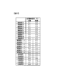
- FIG. 1 is a table showing the compositions of the active materials of the positive electrode and the negative electrode used in Examples and Comparative Examples according to the present invention.
- FIG. 2 is an explanatory diagram of a stacked electrode group inside the lithium ion secondary battery.
- FIG. 3 is a perspective view showing the structure of the lithium ion secondary battery.
- FIG. 4 is a table showing discharge capacity, average potential, energy density, and internal resistance of lithium ion secondary batteries prototyped as examples and comparative examples according to the present invention.
- FIG. 5 is a table showing the potentials of the positive electrode and the negative electrode during discharging of lithium ion secondary batteries produced as examples and comparative examples according to the present invention.
- the positive electrode active material used for the lithium ion secondary battery according to the present invention is represented by the general formula: Li a Mn x Ni y Co z O 2 .
- the positive electrode active material forms a solid solution.
- a, x, y, and z are 1.1 ⁇ a ⁇ 1.2, 0.45 ⁇ x ⁇ 0.55, 0.15 ⁇ y ⁇ 0.35, and 0 ⁇ z ⁇ 0, respectively.
- the negative electrode active material is composed of graphite and Si alloy, and the value of graphite mass / Si alloy mass, which is the mass ratio of graphite and Si alloy, is 0.67 or more and 9 or less.
- the positive electrode active material was prepared by the solid phase method described below. Lithium (Li) and transition metals such as manganese (Mn), nickel (Ni), and cobalt (Co) carbonates are housed in zirconia pots, acetone is added, and then a planetary ball mill is used. A mixed solution was prepared by pulverization and mixing. The raw material powder obtained by drying this mixed solution was fired at 500 ° C. for 12 hours in the air to obtain a temporarily fired body. The calcined product was placed in a zirconia pot, acetone was added, and the mixture was pulverized and mixed using a planetary ball mill device to prepare a raw material solution. After this raw material solution was dried, it was synthesized by firing at 900 to 1050 ° C. for 12 hours in the atmosphere to produce a positive electrode active material.
- Lithium (Li) and transition metals such as manganese (Mn), nickel (Ni), and cobalt (Co) carbonates are housed in zirc
- oxides of these metals can be used instead of using carbonates of lithium, manganese, nickel, and cobalt. Further, a synthesis method such as a coprecipitation method may be used instead of the solid phase method.
- the positive electrode is configured by forming a coating layer of a positive electrode active material mixture containing a positive electrode active material on both surfaces of an aluminum foil as a positive electrode current collector.
- a positive electrode active material mixture prepared by dispersing a positive electrode active material, a binder (binder), and a conductive additive in a solvent is used for the positive electrode current collector. Apply to the surface.
- Polyvinylidene fluoride hereinafter referred to as PVDF
- a carbon material was used as the conductive assistant.
- the mass ratio of the positive electrode active material, the binder, and the conductive material was 90: 5: 5.
- NMP N-methylpyrrolidone
- the coating amount of the positive electrode active material mixture on the positive electrode current collector was 240 g / m 2 .
- the density of the positive electrode active material mixture layer was 2.7 g / cm 3 by a roll press device. A roll press was performed. A positive electrode was produced by the process described above.
- positive electrode active materials having different compositions were prepared by changing the mixing ratio of the carbonates of lithium, manganese, nickel, and cobalt, and positive electrodes using these positive electrode active materials, respectively. Was made.
- the compositions of these positive electrode active materials are shown as Examples 1 to 16 in FIG.
- the negative electrode active material used for the lithium ion secondary battery according to the present invention is composed of a mixture of natural graphite and Si alloy.
- Si metal silicon
- the metal element in which Si is dispersed in the particle or in the Si particle is preferably one or more of Al, Ni, Cu, Fe, Ti, and Mn.
- the atomic ratio of metal elements other than Si and Si is preferably in the range of 50:50 to 90:10, and more preferably in the range of 60:40 to 80:20. That is, the atomic ratio of Si in the Si alloy is preferably 0.5 or more and 0.9 or less, and more preferably 0.6 or more and 0.8.
- the reason why it is preferable to use such an atomic ratio is considered as follows.
- the volume expansion coefficient during charging is suppressed to 130% or less in actual measurement, and 50% or more of Si contributes during discharging.
- the atomic ratio of Si and metal elements other than Si in the Si alloy must be in the above range.
- the volume expansion coefficient during charging is a theoretical value although there are some differences depending on the type of metal element. Is about 110%, and the measured value is about 130%.
- the atomic ratio of the metal element other than Si and Si exceeds 90:10, that is, when the ratio of Si in the Si alloy is too large, in the lithium ion secondary battery manufactured using such a negative electrode active material, The expansion of Si during charging cannot be suppressed by a metal other than Si.
- the atomic ratio of metal elements other than Si and Si is less than 50:50, that is, when the ratio of Si in the Si alloy is too small, there is less Si in the negative electrode active material that contributes to charge / discharge capacity, A lithium ion secondary battery manufactured using such a negative electrode active material has a low charge / discharge capacity.
- compositions of the Si alloy include Si 70 Ti 10 Fe 10 Al 10 (Examples 1 to 8), Si 70 Ti 15 Fe 15 (Example 9), Si 70 Al 10 Ni 20 (Example 10), Si 70 Al 30 (Example 11), Si 70 Ni 30 (Example 12), Si 70 Cu 30 (Example 13), Si 70 Fe 30 (Example 14), Si 70 Ti 30 (Example 15), Si 70 Mn 30 (Example 16) was used.
- the Si alloy can be produced mechanically by a mechanical alloy method, or can be produced by mixing Si particles and a metal element other than Si to form a mixture, and heating and cooling the mixture. In this embodiment, a mechanical alloy method is employed.
- the mixing ratio of Si alloy and natural graphite is such that the mass ratio of natural graphite particles and Si alloy particles is in the range of 40:60 to 90:10. That is, the value of natural graphite mass / Si alloy mass is in the range of 0.67-9.
- the negative electrode is configured by forming a coating layer of a negative electrode active material mixture containing a negative electrode active material on both surfaces of a copper foil as a negative electrode current collector.
- natural graphite and the above Si alloy are mixed at a mixing ratio in the above range to form a negative electrode active material, and a binder and a conductive additive are added to the solvent.
- the negative electrode active material mixture is prepared by dispersing in, and this is applied to the surface of the negative electrode current collector.
- Polyamideimide was used as the binder, and acetylene black was used as the conductive auxiliary.
- a material other than polyamideimide for example, polyimide or polyamide, or one in which one or more of polyamideimide, polyimide, and polyamide are contained in another organic material may be used.
- the mass ratio of the negative electrode active material, the conductive material, and the binder was 93: 2: 5. Further, NMP was used as a solvent, and the viscosity of the negative electrode active material mixture was adjusted according to the amount.
- This negative electrode active material mixture was applied to the surface of the negative electrode current collector to form a coating layer of the negative electrode active material mixture.
- the amount of the negative electrode active material mixture applied to the negative electrode current collector was adjusted so that the positive electrode capacity and the negative electrode capacity were equal.
- After the coating layer formed on the surface of the negative electrode current collector was dried, it was roll-pressed by a roll press device so that the density of the negative electrode active material mixture layer was 2.3 g / cm 3 . Thereafter, heating was performed at 250 ° C. in order to cure the polyamideimide.
- a negative electrode was produced by the above process.
- the mixing ratio of the Si alloy and natural graphite and the composition of the Si alloy are changed to prepare negative electrode active materials having various compositions, and negative electrodes using these negative electrode active materials are prepared. Produced.
- the weight ratio of Si alloy to natural graphite in these negative electrode active materials is shown as Examples 1 to 16 in FIG.
- a procedure for manufacturing a lithium ion secondary battery using the positive electrode and the negative electrode manufactured by the process described above will be described.
- a stacked electrode group was configured using a plurality of positive electrodes and a plurality of negative electrodes. Combinations of positive electrode and negative electrode compositions are shown as Examples 1 to 16 in FIG.
- FIG. 2 shows the configuration of the stacked electrode group.
- the stacked electrode group 9 has a configuration in which a plurality of plate-like positive electrodes 5 and a plurality of plate-like negative electrodes 6 are separated by a plurality of separators 7 and stacked. .
- the compositions of the positive electrode active materials of the plurality of positive electrodes constituting one stacked electrode group are all the same.
- the compositions of the negative electrode active materials of a plurality of negative electrodes constituting one stacked electrode group are all the same.
- a positive electrode uncoated portion 3 where a positive electrode active material mixture is not applied is formed on a part of the positive electrode current collector, and the aluminum foil is exposed in this portion.
- a negative electrode uncoated portion 4 where a negative electrode active material mixture is not applied is formed on a part of the negative electrode current collector, and the copper foil is exposed at this portion.
- the separator 7 should just be comprised with the material which interrupts
- polyolefin can be used.
- Polyolefin is a chain polymer material represented by polyethylene or polypropylene.
- the separator used in Examples 1 to 16 is a composite material of polyethylene and polypropylene.
- a material in which a heat-resistant resin such as polyamide, polyamideimide, polyimide, polysulfone, polyethersulfone, polyphenylsulfone, polyacrylonitrile or the like is added to polyolefin can be used as a material for the separator.
- the inorganic filler layer can be made of a material containing at least one of SiO 2 , Al 2 O 3 , montmorillonite, mica, ZnO, TiO 2 , BaTiO 3 , and ZrO 2 . From the viewpoint of cost and performance, it is preferable to use SiO 2 or Al 2 O 3 .
- the positive electrode uncoated portions 3 of the plurality of positive electrodes 5 constituting the stacked electrode group 9 are bundled together and ultrasonically welded to the positive electrode terminal 1.
- the negative electrode uncoated portions 4 of the plurality of negative electrodes 6 are also bundled together and ultrasonically welded. Electrode welding is not limited to ultrasonic welding, and resistance welding or the like may be used. In order to make the sealing of the lithium ion secondary battery more reliable, a heat welding resin is previously applied to or attached to the portion where the positive electrode terminal 1 and the negative electrode terminal 2 are sealed. It may be left.
- FIG. 3 shows an exploded perspective view of the laminate cell.
- the laminate cell 11 after the laminated electrode group 9 is sandwiched between the laminate films 8 and 10, the peripheral portions of the laminate films 8 and 10 are brought into contact with each other and heated at 175 ° C. for 10 seconds to be thermally welded, It was produced by sealing the periphery.
- As a procedure for sealing in order to provide a liquid injection port for injecting the electrolytic solution into the laminate cell, first, three sides except for one side as the liquid injection port are thermally welded, and the electrolytic solution is supplied from the liquid injection port.
- the gas discharge valve has an effect when gas is generated in the laminate cell as the completed lithium ion secondary battery is charged and discharged.
- a thin portion may be provided in a part of the laminate film 8, and the gas may be discharged from the thin portion.
- An organic electrolytic solution was used as the electrolytic solution.
- EC ethylene carbonate
- EMC ethyl methyl carbonate
- the above laminated cell type lithium ion secondary battery was charged for 22 hours at a constant voltage and constant current of 4.6 V and current of 50 mA, and then discharged at a constant voltage and constant current of 2.0 V and current of 50 mA. went.
- the discharge capacity at this time was determined as the discharge capacity of each lithium ion secondary battery, and the voltage when half of the discharge capacity was discharged was determined as the average voltage.
- the energy of the lithium ion secondary battery is the product of the discharge capacity and the average voltage, and the energy density was determined by dividing the energy by the mass of the lithium ion secondary battery.
- the internal resistance of the lithium ion secondary battery was obtained by charging from a voltage of 2.0 V at a current of 1 A for 10 seconds, and dividing the voltage change at this time by the current of 1 A.
- FIG. 4 shows discharge capacity, average voltage, energy density, and internal resistance for each example.
- FIG. 5 shows the discharge potentials of the positive electrode and the negative electrode during discharge.
- the lithium ion secondary batteries of Examples 1 to 16 have a discharge capacity of 1.1 to 1.2 Ah, an average voltage of 3.5 to 3.6 V, and an energy density of 0.26 to 0.29 kWh / kg.
- the internal resistance is 0.3 ⁇ .
- the discharge potentials of the positive electrode and the negative electrode at the time of 2.0 V discharge were 3.0 to 3.2 V and 1.0 to 1. 2V is shown.
- Lithium ion secondary batteries of Comparative Examples 1 to 6 having the positive electrode active material and the negative electrode active material having the composition shown in FIG. 1 were produced.
- the positive electrode active material of Comparative Example 1 has less Mn and more Co than the positive electrode active material according to the present invention.
- the positive electrode active material of Comparative Example 2 has more Mn and less Ni than the positive electrode active material according to the present invention.
- the negative electrode active material of Comparative Example 3 has a larger graphite / Si alloy mass ratio than the negative electrode active material according to the present invention. That is, there are few Si alloys.
- the graphite / Si alloy mass ratio of the negative electrode active material is smaller than that of the negative electrode active material according to the present invention. That is, there are many Si alloys.
- the negative electrode active material of Comparative Example 5 is composed of only an Si alloy and does not include graphite.
- the negative electrode active material of Comparative Example 6 does not contain a Si alloy, but has a composition containing SiO instead.
- the compositions of the Si alloys contained in the negative electrode active materials of Comparative Examples 1 to 5 are all Si 70 Ti 10 Fe 10 Al 10 .
- the discharge capacity, the average voltage, the energy density, and the internal resistance were determined in the same procedure as that performed for the lithium ion secondary batteries of Examples 1 to 16. Asked. The result is shown in FIG. Further, the discharge potentials of the positive electrode and the negative electrode were measured in the same procedure as that performed for the lithium ion secondary batteries of Examples 1 to 16. The result is shown in FIG.
- Comparative Example 1 has a smaller discharge capacity and lower energy density than Examples 1-16.
- the discharge capacity and the energy density are both about the same as those of Examples 1 to 16, but the internal resistance is large and the value is about twice that of Examples 1 to 16.
- Comparative Example 3 has a smaller discharge capacity and energy density and a higher internal resistance than Examples 1-16. Since the potential of the positive electrode at the time of discharge in Comparative Example 3 is low, this is considered to be a cause of large internal resistance.
- Comparative Examples 4 and 5 have a smaller discharge capacity and energy density than Examples 1-16.
- Comparative Examples 4 and 5 since the positive electrode potential at the time of discharge of Comparative Examples 4 and 5 is high, it can be seen that the capacity of the positive electrode is not sufficiently used, which is considered to be a factor of low energy density. Furthermore, the internal resistances of Comparative Examples 4 and 5 are larger than those of Examples 1-16. This is considered due to the magnitude of the resistance of the Si alloy. That is, the mass ratio of natural graphite in the negative electrode active material is 30 wt% in Comparative Example 4 and 0 wt% in Comparative Example 5, both of which have a high Si alloy ratio. As a result, in the negative electrode using these negative electrode active materials, it is considered that the conductivity is lowered, which is considered to be one of the causes of the increase in internal resistance.
- Comparative Example 6 has a smaller discharge capacity and energy density than Examples 1-16.
- the negative electrode active material of Comparative Example 6 is a mixture of SiO and graphite, and since the positive electrode potential during discharge is high, it can be seen that the capacity of the positive electrode is not sufficiently used. This is considered to be a factor of low energy density.
- the irreversible capacity is about 10% higher than the negative electrode using the negative electrode active material in which Si alloy and natural graphite are mixed. This is considered to be a factor that lowered the energy density.
- the lithium ion secondary battery is in the form of a laminated laminate cell, but it goes without saying that the present invention can also be applied to lithium-in secondary batteries having other configurations.
- the present invention can be applied to a wound structure or a metal can.
- a lithium ion secondary battery having both a high energy density and a low internal resistance can be provided.
Landscapes
- Chemical & Material Sciences (AREA)
- Chemical Kinetics & Catalysis (AREA)
- Electrochemistry (AREA)
- General Chemical & Material Sciences (AREA)
- Inorganic Chemistry (AREA)
- Engineering & Computer Science (AREA)
- Materials Engineering (AREA)
- Manufacturing & Machinery (AREA)
- Battery Electrode And Active Subsutance (AREA)
- Secondary Cells (AREA)
Abstract
正極と負極と電解質とを有するリチウムイオン二次電池であって、正極の活物質は、一般式:LiaMnxNiyCozO2(式中、a、x、yおよびzは、1.1≦a≦1.2、0.45≦x≦0.55、0.15≦y≦0.35、0≦z≦0.15を満たすパラメータである)で表され、負極の活物質は黒鉛とSi合金とからなり、黒鉛とSi合金の質量比である、黒鉛質量/Si合金質量の値は、0.67以上、かつ、9以下ある。
Description
本発明は、リチウムイオン二次電池に関する。
近年、地球温暖化や化石燃料枯渇の問題から、エネルギー消費の少ない電気自動車(EV)が各自動車メーカーにより開発されている。電気自動車の電源としては、エネルギー密度が高いリチウムイオン二次電池が求められているが、現状では十分なエネルギー密度を有するリチウムイオン二次電池は得られていない。
高いエネルギー密度のリチウムイオン二次電池を実現する正極活物質として、Li2MO3-LiM’O2固溶体が期待されている。ここで、Mは、Mn,Ti,Zrから選ばれる1種類以上の元素であり、M’は、Ni,Co,Mn,Fe,Ti,Zr,Al,Mg,Cr,Vから選ばれる1種類以上の元素である。
特許文献1には、Li[Ni0.17Li0.2Co0.07Mn0.56]O2)固溶体系正極を用いてリチウムイオン二次電池を構成し、段階的に容量を上げて充電することで、高容量と高電位での充放電による劣化抑制が実現されることが記載されている。
特許文献2には、Si合金と炭素質材料の複合体による負極活物質を用いてリチウムイオン二次電池を構成することで、高容量とサイクル特性の低下抑制が実現されることが記載されている。
しかし、固溶体を用いた正極やSi合金を含有する負極に対して、技術的な改良が種々行われているものの、高いエネルギー密度と低い内部抵抗を併せ持つリチウムイオン二次電池は実現されていない。
本発明のリチウムイオン二次電池は、正極と負極と電解質とを有し、正極の活物質は、一般式:LiaMnxNiyCozO2(式中、a、x、y、およびzはそれぞれ、1.1≦a≦1.2、0.45≦x≦0.55、0.15≦y≦0.35、および0≦z≦0.15を満たすパラメータである)で表され、負極の活物質は、黒鉛とSi合金とからなり、黒鉛とSi合金の質量比である黒鉛質量/Si合金質量の値は、0.67以上、かつ、9以下である。
本発明によれば、エネルギー密度が高く、かつ、内部抵抗の低いリチウムイオン二次電池を提供できる。
本発明に係るリチウムイオン二次電池の実施の形態について説明する。
<正極活物質および正極の作製>
本発明に係るリチウムイオン二次電池に用いる正極活物質は、一般式:LiaMnxNiyCozO2で表される。正極活物質は固溶体をなしている。式中、a、x、y、およびzはそれぞれ、1.1≦a≦1.2、0.45≦x≦0.55、0.15≦y≦0.35、および0≦z≦0.15を満たすパラメータである。また、負極活物質は、黒鉛とSi合金とからなり、黒鉛とSi合金の質量比である黒鉛質量/Si合金質量の値は0.67以上、かつ、9以下である。
<正極活物質および正極の作製>
本発明に係るリチウムイオン二次電池に用いる正極活物質は、一般式:LiaMnxNiyCozO2で表される。正極活物質は固溶体をなしている。式中、a、x、y、およびzはそれぞれ、1.1≦a≦1.2、0.45≦x≦0.55、0.15≦y≦0.35、および0≦z≦0.15を満たすパラメータである。また、負極活物質は、黒鉛とSi合金とからなり、黒鉛とSi合金の質量比である黒鉛質量/Si合金質量の値は0.67以上、かつ、9以下である。
本実施の形態の各実施例においては、正極活物質は次に説明する固相法にて作製した。リチウム(Li)と、遷移金属であるマンガン(Mn)、ニッケル(Ni)、コバルト(Co)それぞれの炭酸塩をジルコニア製のポットに収容し、アセトンを加えた後、遊星型ボールミル装置を用いて粉砕・混合して混合溶液を作製した。この混合溶液を乾燥して得た原料粉末を、大気中において500℃で12時間焼成して仮焼成体を得た。仮焼成体をジルコニア製ポットに収容してアセトンを加え、遊星型ボールミル装置を用いて粉砕・混合して原料溶液を作製した。この原料溶液を乾燥した後、大気中において900~1050℃で12時間焼成して合成し正極活物質を作製した。
なお、正極活物質の作製には、リチウム、マンガン、ニッケル、およびコバルトそれぞれの炭酸塩を用いる代わりに、これらの金属の酸化物を用いることも可能である。また、固相法の代わりに、共沈法等の合成方法を用いてもよい。
正極は、正極集電体としてのアルミニウム箔の両面に、正極活物質を含む正極活物質合剤の塗工層が形成されて構成される。正極活物質合剤の塗工層を形成するには、正極活物質とバインダ(結着材)と導電助剤とを溶媒中に分散させて調整した正極活物質合剤を正極集電体の表面に塗工する。バインダとしてはポリフッ化ビニリデン(以下、PVDFと記載する)を用い、導電助剤としては炭素材料を用いた。正極活物質、バインダ、および導電材の質量比は90:5:5とした。また、溶媒としてはN-メチルピロリドン(以下、NMPと略記する)を用い、その量により正極活物質合剤の粘度調整を行った。正極集電体への正極活物質合剤の塗工量は240g/m2とした。正極活物質合剤を塗工した正極集電体は、正極活物質合剤の塗工層を乾燥させた後、ロールプレス装置により正極活物質合剤層の密度が2.7g/cm3となるようにロールプレスした。以上説明した工程により正極を作製した。
正極活物質を作製する際には、リチウム、マンガン、ニッケル、およびコバルトのそれぞれの炭酸塩の混合比率を変化させて異なる組成の正極活物質を作製し、これらの正極活物質をそれぞれ用いた正極を作製した。これらの正極活物質の組成を、図1に実施例1~16として示す。
<負極活物質および負極の作製>
本発明に係るリチウムイオン二次電池に用いる負極活物質は、天然黒鉛とSi合金の混合物からなる。Si合金においては、金属ケイ素(Si)の微細な粒子がSi以外の金属元素の各粒子中に分散された状態となっているか、または、Si以外の金属元素がSiの各粒子中に分散された状態となっている。Siを粒子内部に分散させる、または、Si粒子中に分散させる金属元素としては、Al、Ni、Cu、Fe、Ti、Mnのいずれか1種類または2種類以上であることが好ましい。
本発明に係るリチウムイオン二次電池に用いる負極活物質は、天然黒鉛とSi合金の混合物からなる。Si合金においては、金属ケイ素(Si)の微細な粒子がSi以外の金属元素の各粒子中に分散された状態となっているか、または、Si以外の金属元素がSiの各粒子中に分散された状態となっている。Siを粒子内部に分散させる、または、Si粒子中に分散させる金属元素としては、Al、Ni、Cu、Fe、Ti、Mnのいずれか1種類または2種類以上であることが好ましい。
Si合金は、SiとSi以外の金属元素の原子比率が、50:50~90:10の範囲であることが好ましく、60:40~80:20の範囲であればより好ましい。即ち、Si合金に占めるSiの原子比率が、0.5以上、かつ、0.9以下であることが好ましく、0.6以上、かつ、0.8であることがより好ましい。このような原子比率とすることが好ましい理由は次のように考えられる。SiとのSiO2をモル比で50:50となるようにSiO2粒子中にSi結晶を分散させた負極活物質をリチウムイオン二次電池の負極に用いた場合、充電時における負極活物質の体積膨張率は、理論値で130%、実測値で150%であった。これらの値に基づいて、Si合金を負極活物質に用いた場合に、充電時の体積膨張率を実測値で130%以下に抑え、かつ、放電時にSiの50%以上が寄与するようにするためには、Si合金におけるSiとSi以外の金属元素の原子比率が上記範囲となるようにすることが必要であることがわかった。因みに、SiとSi以外の金属元素の原子比率が80:20のSi合金を負極活物質に用いた場合、金属元素の種類による多少の違いはあるものの、充電時の体積膨張率は、理論値で約110%、実測値で約130%である。
SiとSi以外の金属元素の原子比率が90:10を超える、即ち、Si合金に占めるSiの比率が大き過ぎる場合、このような負極活物質を用いて作製したリチウムイオン二次電池においては、充電時のSiの膨張をSi以外の金属により抑えることができない。逆に、SiとSi以外の金属元素の原子比率が50:50を下回る、即ち、Si合金に占めるSiの比率が小さ過ぎる場合、充放電容量に寄与する負極活物質中のSiが少ないため、このような負極活物質を用いて作製したリチウムイオン二次電池は充放電容量が低い。
Si合金の具体的な組成としては、Si70Ti10Fe10Al10(実施例1~8)、Si70Ti15Fe15(実施例9)、Si70Al10Ni20(実施例10)、Si70Al30(実施例11)、Si70Ni30(実施例12)、Si70Cu30(実施例13)、Si70Fe30(実施例14)、Si70Ti30(実施例15)、Si70Mn30(実施例16)とした。
Si合金は、メカニカルアロイ法により機械的に作製するか、またはSi粒子とSi以外の金属元素とを混合させて混合物とし、これを加熱した後、冷却することで作製することができる。本実施形態においては、メカニカルアロイ法を採用した。
Si合金と天然黒鉛との混合比は、天然黒鉛粒子とSi合金粒子のそれぞれ質量比が40:60~90:10の範囲とする。即ち、天然黒鉛質量/Si合金質量の値が0.67~9の範囲である。
負極は、負極集電体としての銅箔の両面に、負極活物質を含む負極活物質合剤の塗工層が形成されて構成される。負極活物質合剤の塗工層を形成するには、天然黒鉛と上記のSi合金とを上記範囲の混合比で混合して負極活物質をし、さらにバインダと導電助剤とを加えて溶媒中に分散させて負極活物質合剤を調整し、これを負極集電体の表面に塗工する。バインダとしてはポリアミドイミドを用い、導電助剤としてはアセチレンブラックを用いた。なお、バインダとしては、ポリアミドイミド以外の材料、例えば、ポリイミドやポリアミド、あるいは、ポリアミドイミド、ポリイミド、ポリアミドのうちの1種類以上を別の有機材料に含有させたものを用いてもよい。負極活物質、導電材、およびバインダの質量比は93:2:5とした。また、溶媒としてはNMPを用い、その量により負極活物質合剤の粘度調整を行った。
この負極活物質合剤を負極集電体の表面に塗工して負極活物質合剤の塗工層を形成した。負極集電体への負極活物質合剤の塗工量は、正極の容量と負極の容量が等しくなるように調節した。負極集電体の表面に形成した塗工層を乾燥させた後、ロールプレス装置により負極活物質合剤層の密度が2.3g/cm3となるようにロールプレスした。その後、ポリアミドイミドを硬化させるために250℃で加熱した。上記工程により負極を作製した。
負極活物質を作製する際には、Si合金と天然黒鉛の混合比やSi合金の組成を変化させて、種々の組成の負極活物質を作製し、これらの負極活物質をそれぞれ用いた負極を作製した。これらの負極活物質におけるSi合金と天然黒鉛の重量比について、図1に実施例1~16として示す。
<リチウムイオン二次電池の作製>
上記説明の工程により作製した正極と負極を用いて、リチウムイオン二次電池を作製する手順について説明する。複数の正極と複数の負極を用いて積層型電極群を構成した。正極と負極の組成の組み合わせは、図1に実施例1~16として示した。
上記説明の工程により作製した正極と負極を用いて、リチウムイオン二次電池を作製する手順について説明する。複数の正極と複数の負極を用いて積層型電極群を構成した。正極と負極の組成の組み合わせは、図1に実施例1~16として示した。
図2には積層型電極群の構成を示す。図2に示したように、積層型電極群9は、複数の板状の正極5と複数の板状の負極6との間が複数のセパレータ7で隔てられて積層された構成となっている。一つの積層型電極群を構成する複数の正極の正極活物質の組成は全て同じものである。同様に、一つの積層型電極群を構成する複数の負極の負極活物質の組成も全て同じものである。正極5には、正極集電体の一部に正極活物質合剤の塗工されない正極未塗工部3が形成されており、この部分ではアルミニウム箔が露出している。同様に、負極6には、負極集電体の一部に負極活物質合剤の塗工されない負極未塗工部4が形成されており、この部分では銅箔が露出している。
セパレータ7は、リチウムイオン二次電池が何らかの原因により発熱した際に、熱収縮によりリチウムイオンの移動を遮断する材料により構成されていればよい。このような材料として、例えば、ポリオレフィンを用いることができる。ポリオレフィンは、ポリエチレンやポリプロピレンをその代表とする鎖状の高分子材料である。実施例1~16に用いたセパレータは、ポリエチレンとポリプロピレンの複合材である。なお、他にセパレータの材料として、ポリオレフィンに対して、ポリアミド、ポリアミドイミド、ポリイミド、ポリスルホン、ポリエーテルスルホン、ポリフェニルスルホン、ポリアクリロニトリル等の耐熱性樹脂を含有させたものも用いることができる。さらに、セパレータの片面もしくは両面に無機フィラー層を形成してもよい。無機フィラー層としては、SiO2、Al2O3、モンモリロナイト、雲母、ZnO、TiO2、BaTiO3、ZrO2のうちの少なくとも1種類を含む材料により構成できる。コストや性能の観点からは、SiO2またはAl2O3を用いることが好ましい。
積層型電極群9を構成する複数の正極5の正極未塗工部3は互いに束ねられて正極端子1に超音波溶接される。また、複数の負極6の負極未塗工部4も互いに束ねられて超音波溶接される。電極の溶接は超音波溶接に限らず、抵抗溶接等を用いてもよい。リチウムイオン二次電池の封止をより確実にするために、正極端子1および負極端子2が封止される箇所には、あらかじめ熱溶着樹脂を端子の封止箇所に塗布するか、あるいは取り付けておいてもよい。
上記積層型電極群をラミネートフィルムに収納してラミネートセル型リチウムイオン二次電池を作製した。図3にこのラミネートセルの分解斜視図を示す。ラミネートセル11は、積層型電極群9を、ラミネートフィルム8および10で挟んだ後、ラミネートフィルム8および10の周縁部を互いに接触させた状態で、175℃で10秒間加熱して熱溶着させ、周縁部を封止することにより作製した。封止する手順としては、電解液をラミネートセル内に注入するための注液口を設けるために、まず、注液口とする一辺を除いた三辺を熱溶着し、注液口から電解液をラミネートセル内に注液した後に、注液口とした一辺を真空加圧しながら熱溶着を行い封止した。注液口とした一辺は、他の三辺に比べて熱溶着強度が弱くなるように調整した。これは、完成したリチウムイオン二次電池の充放電に伴ってラミネートセル内にガスが発生した場合に、ガス排出弁の効果を持たせるためである。ガス排出のための手段としては上記のような構成とする以外に、ラミネートフィルム8の一部に薄肉部を設け、この薄肉部からガスが排出されるようにしてもよい。
電解液としては有機電解液を用いた。この有機電解液は、電解質として1mol/dm-3のLiPF6を、エチレンカーボネート(EC):エチルメチルカーボネート(EMC)=1:3(vol%)の有機溶媒に溶解させたものである。電解液としては上記の他に、例えば、エチレンカーボネート、プロピレンカーボネート、ブチレンカーボネート、ジメチルカーボネート、エチルメチルカーボネート、ジエチルカーボネート、γ-ブチロラクトン、γ-バレロラクトン、メチルアセテート、エチルアセテート、メチルプロピオネート、テトラヒドロフラン、2-メチルテトラヒドロフラン、1,2-ジメトキシエタン、1-エトキシ-2-メトキシエタン、3-メチルテトラヒドロフラン、1,2-ジオキサン、1,3-ジオキサン、1,4-ジオキサン、1,3-ジオキソラン、2-メチル-1,3-ジオキソラン、4-メチル-1,3-ジオキソラン等のうちの少なくとも1種以上で構成された非水溶媒に、例えば、LiPF6、LiBF4、LiClO4、LiN(C2F5SO2)2等のうち少なくとも1種以上のリチウム塩を溶解させた有機電解液、あるいは、リチウムイオンの伝導性を有する固体電解質、あるいは、ゲル状電解質、あるいは、溶融塩等、既知のものを用いることができる。
<放電容量、平均電圧、エネルギー密度、および内部抵抗>
上記のラミネートセル型リチウムイオン二次電池に対して、電圧4.6V、電流50mAの定電圧定電流で22時間充電を行った後、電圧2.0V、電流50mAの定電圧定電流で放電を行った。このときの放電容量をそれぞれのリチウムイオン二次電池の放電容量とし、放電容量の半分が放電したときの電圧を平均電圧として各々求めた。リチウムイオン二次電池のエネルギーは、放電容量と平均電圧の積であり、エネルギー密度は、エネルギーをリチウムイオン二次電池の質量で除算して求めた。リチウムイオン二次電池の内部抵抗は、電圧2.0Vから電流1Aで10秒間充電し、このときの電圧変化を電流1Aで除算して求めた。図4に、放電容量、平均電圧、エネルギー密度、および内部抵抗を実施例毎に示す。
上記のラミネートセル型リチウムイオン二次電池に対して、電圧4.6V、電流50mAの定電圧定電流で22時間充電を行った後、電圧2.0V、電流50mAの定電圧定電流で放電を行った。このときの放電容量をそれぞれのリチウムイオン二次電池の放電容量とし、放電容量の半分が放電したときの電圧を平均電圧として各々求めた。リチウムイオン二次電池のエネルギーは、放電容量と平均電圧の積であり、エネルギー密度は、エネルギーをリチウムイオン二次電池の質量で除算して求めた。リチウムイオン二次電池の内部抵抗は、電圧2.0Vから電流1Aで10秒間充電し、このときの電圧変化を電流1Aで除算して求めた。図4に、放電容量、平均電圧、エネルギー密度、および内部抵抗を実施例毎に示す。
<正極と負極における放電電位>
エネルギーおよび内部抵抗の測定が終わった後、リチウムイオン二次電池を解体して正極および負極を取り出し、リチウム金属参照極を備えた小型テストセルに装着して、2.0Vで放電させ、このときの正極および負極の放電電位をそれぞれ測定した。図5に放電時の正極および負極の放電電位を示す。
エネルギーおよび内部抵抗の測定が終わった後、リチウムイオン二次電池を解体して正極および負極を取り出し、リチウム金属参照極を備えた小型テストセルに装着して、2.0Vで放電させ、このときの正極および負極の放電電位をそれぞれ測定した。図5に放電時の正極および負極の放電電位を示す。
図4からわかる通り、実施例1~16のリチウムイオン二次電池は、放電容量1.1~1.2Ah、平均電圧3.5~3.6V、エネルギー密度0.26~0.29kWh/kg、内部抵抗0.3Ωを示している。また、図5からわかる通り、実施例1~16のリチウムイオン二次電池は、2.0V放電時の正極および負極の放電電位は、それぞれ3.0~3.2Vと1.0~1.2Vを示している。
正極活物質および負極活物質を図1に示す組成とした比較例1~6のリチウムイオン二次電池を作製した。比較例1の正極活物質は本発明に係る正極活物質に比べてMnが少なくCoが多い。比較例2の正極活物質は本発明に係る正極活物質に比べてMnが多くNiが少ない。比較例3の負極活物質は本発明に係る負極活物質に比べて黒鉛/Si合金の質量比が大きい。即ち、Si合金が少ない。比較例4は本発明に係る負極活物質に比べて負極活物質の黒鉛/Si合金の質量比が小さい。即ち、Si合金が多い。比較例5の負極活物質はSi合金のみで構成されており黒鉛が含まれない。比較例6の負極活物質がSi合金を含まず、代わりにSiOを含む組成となっている。なお、比較例1~5の負極活物質に含まれるSi合金の組成はいずれもSi70Ti10Fe10Al10である。
比較例1~6のリチウムイオン二次電池に対して、実施例1~16のリチウムイオン二次電池に対して行った手順と同様の手順により、放電容量、平均電圧、エネルギー密度および内部抵抗を求めた。その結果を図4に示す。また、実施例1~16のリチウムイオン二次電池に対して行った手順と同様の手順で、正極および負極の放電電位を測定した。その結果を図5に示す。
図4および図5からわかる通り、比較例1は、実施例1~16に比べて放電容量が小さくエネルギー密度も小さい。比較例2は、放電容量とエネルギー密度については共に実施例1~16と同程度であるものの、内部抵抗が大きくその値は実施例1~16の2倍程度となっている。このようなリチウムイオン二次電池をEVに搭載することを想定した場合、急速充電する際に問題がある。比較例3は、実施例1~16に比べて放電容量もエネルギー密度も共に小さく、内部抵抗は大きい。比較例3の放電時における正極の電位が低いことから、このことが内部抵抗の大きい要因と考えられる。比較例4および5は、実施例1~16に比べて放電容量もエネルギー密度も共に小さい。また、比較例4および5の放電時の正極電位は高いことから、正極の容量が十分に使われていないことがわかり、このことがエネルギー密度の低い要因と考えられる。さらに、比較例4および5の内部抵抗は実施例1~16に比べて大きい。これはSi合金の抵抗の大きさに起因するものと考えられる。即ち、負極活物質に占める天然黒鉛の質量比が、比較例4では30wt%、比較例5では0wt%であり、共にSi合金の比率が高い。その結果、これらの負極活物質を用いた負極においては導電性が低下したものと考えられ、このことが内部抵抗増大の要因の一つと考えられる。比較例6は、実施例1~16に比べて放電容量もエネルギー密度も共に小さい。比較例6の負極活物質は、SiOと黒鉛とが混合されたものであり、放電時の正極電位が高いことから、正極の容量が十分に使われていないことがわかる。このことがエネルギー密度の低い要因と考えられる。なお、SiOと天然黒鉛とを混合した負極活物質を用いた負極では、Si合金と天然黒鉛とを混合した負極活物質を用いた負極に比べて不可逆容量が10%程度高いことも、容量とエネルギー密度が低下した要因であると考えられる。
実施例1~16では、リチウムイオン二次電池として積層型のラミネートセルの形態としたが、本発明は、それ以外の構成のリチウムイン二次電池にも適用できることは言うまでもない。例えば、捲回構造のものや金属缶に封入されたものに対しても適用可能である。
以上説明した通り、本発明によれば、高いエネルギー密度と低い内部抵抗を併せ持つリチウムイオン二次電池を提供できる。
上記の通り、種々の実施の形態及び変形例について説明したが、本発明はこれらの内容に限定されるものではない。本発明の技術的思想の範囲内で考えられるその他の態様も本発明の範囲内に含まれる。
1 正極端子
2 負極端子
3 正極未塗工部
4 負極未塗工部
5 正極
6 負極
7 セパレータ
8 ラミネートフィルム
9 積層型電極群
10 ラミネートフィルム
11 ラミネートセル
2 負極端子
3 正極未塗工部
4 負極未塗工部
5 正極
6 負極
7 セパレータ
8 ラミネートフィルム
9 積層型電極群
10 ラミネートフィルム
11 ラミネートセル
Claims (5)
- 正極と負極と電解質とを有するリチウムイオン二次電池であって、
前記正極の活物質は、一般式:
LiaMnxNiyCozO2
(式中、a、x、y、およびzはそれぞれ、1.1≦a≦1.2、0.45≦x≦0.55、0.15≦y≦0.35、および0≦z≦0.15を満たすパラメータである)で表され、
前記負極の活物質は、黒鉛とSi合金とからなり、前記黒鉛と前記Si合金の質量比である、黒鉛質量/Si合金質量の値が0.67以上、かつ、9以下であるリチウムイオン二次電池。
- 請求項1に記載のリチウムイオン二次電池において、
前記Si合金は、Siと、Al、Ni、Cu、Fe、Ti、Mnのグループから選択されたいずれか1種または2種以上を含むリチウムイオン二次電池。
- 請求項1または2に記載のリチウムイオン二次電池において、
前記Si合金に占めるSiの原子比率は、0.5以上、かつ、0.9以下であるリチウムイオン二次電池。
- 請求項1または2に記載のリチウムイオン二次電池において、
前記Si合金に占めるSiの原子比率は、0.6以上、かつ、0.8以下であるリチウムイオン二次電池。
- 請求項1~4のいずれか一項に記載のリチウムイオン二次電池において、
負極に用いるバインダは、ポリアミドイミド、ポリイミド、ポリアミドのいずれか1種または2種以上を含むリチウムイオン二次電池。
Priority Applications (2)
| Application Number | Priority Date | Filing Date | Title |
|---|---|---|---|
| JP2016505967A JPWO2015132856A1 (ja) | 2014-03-03 | 2014-03-03 | リチウムイオン二次電池 |
| PCT/JP2014/055281 WO2015132856A1 (ja) | 2014-03-03 | 2014-03-03 | リチウムイオン二次電池 |
Applications Claiming Priority (1)
| Application Number | Priority Date | Filing Date | Title |
|---|---|---|---|
| PCT/JP2014/055281 WO2015132856A1 (ja) | 2014-03-03 | 2014-03-03 | リチウムイオン二次電池 |
Publications (1)
| Publication Number | Publication Date |
|---|---|
| WO2015132856A1 true WO2015132856A1 (ja) | 2015-09-11 |
Family
ID=54054699
Family Applications (1)
| Application Number | Title | Priority Date | Filing Date |
|---|---|---|---|
| PCT/JP2014/055281 Ceased WO2015132856A1 (ja) | 2014-03-03 | 2014-03-03 | リチウムイオン二次電池 |
Country Status (2)
| Country | Link |
|---|---|
| JP (1) | JPWO2015132856A1 (ja) |
| WO (1) | WO2015132856A1 (ja) |
Cited By (6)
| Publication number | Priority date | Publication date | Assignee | Title |
|---|---|---|---|---|
| WO2016076014A1 (ja) * | 2014-11-11 | 2016-05-19 | 日立オートモティブシステムズ株式会社 | リチウムイオン二次電池および電池システム |
| JP2016100329A (ja) * | 2014-11-25 | 2016-05-30 | イルジン エレクトリック カンパニー リミテッド | 二次電池用負極活物質及びこれを用いた二次電池 |
| WO2017077986A1 (ja) * | 2015-11-06 | 2017-05-11 | 株式会社日立製作所 | リチウムイオン二次電池およびリチウムイオン二次電池の製造方法 |
| JP2018502419A (ja) * | 2014-11-25 | 2018-01-25 | イルジン エレクトリック カンパニー リミテッド | 二次電池用負極活物質およびこれを用いた二次電池 |
| JP2018503234A (ja) * | 2015-02-26 | 2018-02-01 | イルジン エレクトリック カンパニー リミテッド | リチウム二次電池用負極板およびこれを含むリチウム二次電池 |
| WO2024042871A1 (ja) * | 2022-08-26 | 2024-02-29 | パナソニックIpマネジメント株式会社 | 非水電解質二次電池 |
Citations (3)
| Publication number | Priority date | Publication date | Assignee | Title |
|---|---|---|---|---|
| JP2005276821A (ja) * | 2004-02-24 | 2005-10-06 | Sumitomo Metal Ind Ltd | 非水系二次電池用負極材料とその製造方法 |
| WO2010150513A1 (ja) * | 2009-06-23 | 2010-12-29 | キヤノン株式会社 | 電極構造体及び蓄電デバイス |
| JP2014010909A (ja) * | 2012-06-27 | 2014-01-20 | Asahi Kasei Corp | 複合酸化物及びその製造方法、並びに非水系二次電池 |
-
2014
- 2014-03-03 JP JP2016505967A patent/JPWO2015132856A1/ja active Pending
- 2014-03-03 WO PCT/JP2014/055281 patent/WO2015132856A1/ja not_active Ceased
Patent Citations (3)
| Publication number | Priority date | Publication date | Assignee | Title |
|---|---|---|---|---|
| JP2005276821A (ja) * | 2004-02-24 | 2005-10-06 | Sumitomo Metal Ind Ltd | 非水系二次電池用負極材料とその製造方法 |
| WO2010150513A1 (ja) * | 2009-06-23 | 2010-12-29 | キヤノン株式会社 | 電極構造体及び蓄電デバイス |
| JP2014010909A (ja) * | 2012-06-27 | 2014-01-20 | Asahi Kasei Corp | 複合酸化物及びその製造方法、並びに非水系二次電池 |
Cited By (9)
| Publication number | Priority date | Publication date | Assignee | Title |
|---|---|---|---|---|
| WO2016076014A1 (ja) * | 2014-11-11 | 2016-05-19 | 日立オートモティブシステムズ株式会社 | リチウムイオン二次電池および電池システム |
| JP2016091962A (ja) * | 2014-11-11 | 2016-05-23 | 日立オートモティブシステムズ株式会社 | リチウムイオン二次電池および電池システム |
| JP2016100329A (ja) * | 2014-11-25 | 2016-05-30 | イルジン エレクトリック カンパニー リミテッド | 二次電池用負極活物質及びこれを用いた二次電池 |
| JP2018502419A (ja) * | 2014-11-25 | 2018-01-25 | イルジン エレクトリック カンパニー リミテッド | 二次電池用負極活物質およびこれを用いた二次電池 |
| JP2018503234A (ja) * | 2015-02-26 | 2018-02-01 | イルジン エレクトリック カンパニー リミテッド | リチウム二次電池用負極板およびこれを含むリチウム二次電池 |
| JP7000155B2 (ja) | 2015-02-26 | 2022-01-19 | イルジン エレクトリック カンパニー リミテッド | リチウム二次電池用負極板およびこれを含むリチウム二次電池 |
| WO2017077986A1 (ja) * | 2015-11-06 | 2017-05-11 | 株式会社日立製作所 | リチウムイオン二次電池およびリチウムイオン二次電池の製造方法 |
| JPWO2017077986A1 (ja) * | 2015-11-06 | 2018-06-14 | 株式会社日立製作所 | リチウムイオン二次電池およびリチウムイオン二次電池の製造方法 |
| WO2024042871A1 (ja) * | 2022-08-26 | 2024-02-29 | パナソニックIpマネジメント株式会社 | 非水電解質二次電池 |
Also Published As
| Publication number | Publication date |
|---|---|
| JPWO2015132856A1 (ja) | 2017-03-30 |
Similar Documents
| Publication | Publication Date | Title |
|---|---|---|
| KR102633418B1 (ko) | 비수전해질 이차 전지용 부극 활물질 및 비수전해질 이차 전지, 그리고 비수전해질 이차 전지용 부극재의 제조 방법 | |
| JP6466161B2 (ja) | リチウムイオン電池用負極材料 | |
| JP6517007B2 (ja) | リチウムイオン二次電池の製造方法 | |
| JP5936406B2 (ja) | リチウムイオン二次電池 | |
| JP6422742B2 (ja) | リチウムイオン二次電池および電池システム | |
| JP6476094B2 (ja) | リチウムイオン二次電池 | |
| JP2018181539A (ja) | リチウムイオン二次電池用負極 | |
| JP6518061B2 (ja) | リチウムイオン二次電池 | |
| WO2014010312A1 (ja) | 二次電池の充電制御方法および充電制御装置 | |
| JPWO2015132856A1 (ja) | リチウムイオン二次電池 | |
| WO2017077986A1 (ja) | リチウムイオン二次電池およびリチウムイオン二次電池の製造方法 | |
| JP2019029212A (ja) | リチウムイオン二次電池およびその製造方法 | |
| JP6067844B2 (ja) | リチウムイオン二次電池 | |
| JP2018107053A (ja) | リチウムイオン二次電池 | |
| WO2015079549A1 (ja) | リチウムイオン二次電池およびその製造方法、リチウムイオン二次電池用結着剤溶液 | |
| JP2017091886A (ja) | 非水電解液二次電池 | |
| US9960459B2 (en) | Method of manufacturing nonaqueous electrolyte secondary battery | |
| JP6639889B2 (ja) | 二次電池 | |
| JP6718784B2 (ja) | リチウムイオン二次電池 | |
| JP6120101B2 (ja) | 非水電解質二次電池およびその製造方法 | |
| JP2018206619A (ja) | リチウムイオン二次電池 | |
| JP2016167394A (ja) | リチウムイオン電池 | |
| JP2019153539A (ja) | 非水電解質二次電池 | |
| JP2011113770A (ja) | リチウム電池 | |
| JP2018181695A (ja) | リチウムイオン二次電池 |
Legal Events
| Date | Code | Title | Description |
|---|---|---|---|
| 121 | Ep: the epo has been informed by wipo that ep was designated in this application |
Ref document number: 14884275 Country of ref document: EP Kind code of ref document: A1 |
|
| ENP | Entry into the national phase |
Ref document number: 2016505967 Country of ref document: JP Kind code of ref document: A |
|
| NENP | Non-entry into the national phase |
Ref country code: DE |
|
| 122 | Ep: pct application non-entry in european phase |
Ref document number: 14884275 Country of ref document: EP Kind code of ref document: A1 |