WO2015129746A1 - 紙幣識別装置 - Google Patents
紙幣識別装置 Download PDFInfo
- Publication number
- WO2015129746A1 WO2015129746A1 PCT/JP2015/055389 JP2015055389W WO2015129746A1 WO 2015129746 A1 WO2015129746 A1 WO 2015129746A1 JP 2015055389 W JP2015055389 W JP 2015055389W WO 2015129746 A1 WO2015129746 A1 WO 2015129746A1
- Authority
- WO
- WIPO (PCT)
- Prior art keywords
- banknote
- bill
- transport
- moving
- guide
- Prior art date
- Legal status (The legal status is an assumption and is not a legal conclusion. Google has not performed a legal analysis and makes no representation as to the accuracy of the status listed.)
- Ceased
Links
Images

















Classifications
-
- B—PERFORMING OPERATIONS; TRANSPORTING
- B65—CONVEYING; PACKING; STORING; HANDLING THIN OR FILAMENTARY MATERIAL
- B65H—HANDLING THIN OR FILAMENTARY MATERIAL, e.g. SHEETS, WEBS, CABLES
- B65H5/00—Feeding articles separated from piles; Feeding articles to machines
- B65H5/36—Article guides or smoothers, e.g. movable in operation
-
- B—PERFORMING OPERATIONS; TRANSPORTING
- B65—CONVEYING; PACKING; STORING; HANDLING THIN OR FILAMENTARY MATERIAL
- B65H—HANDLING THIN OR FILAMENTARY MATERIAL, e.g. SHEETS, WEBS, CABLES
- B65H9/00—Registering, e.g. orientating, articles; Devices therefor
- B65H9/10—Pusher and like movable registers; Pusher or gripper devices which move articles into registered position
- B65H9/101—Pusher and like movable registers; Pusher or gripper devices which move articles into registered position acting on the edge of the article
-
- G—PHYSICS
- G07—CHECKING-DEVICES
- G07F—COIN-FREED OR LIKE APPARATUS
- G07F7/00—Mechanisms actuated by objects other than coins to free or to actuate vending, hiring, coin or paper currency dispensing or refunding apparatus
- G07F7/04—Mechanisms actuated by objects other than coins to free or to actuate vending, hiring, coin or paper currency dispensing or refunding apparatus by paper currency
-
- B—PERFORMING OPERATIONS; TRANSPORTING
- B65—CONVEYING; PACKING; STORING; HANDLING THIN OR FILAMENTARY MATERIAL
- B65H—HANDLING THIN OR FILAMENTARY MATERIAL, e.g. SHEETS, WEBS, CABLES
- B65H2403/00—Power transmission; Driving means
- B65H2403/40—Toothed gearings
- B65H2403/45—Toothed gearings helical gearing
-
- B—PERFORMING OPERATIONS; TRANSPORTING
- B65—CONVEYING; PACKING; STORING; HANDLING THIN OR FILAMENTARY MATERIAL
- B65H—HANDLING THIN OR FILAMENTARY MATERIAL, e.g. SHEETS, WEBS, CABLES
- B65H2404/00—Parts for transporting or guiding the handled material
- B65H2404/70—Other elements in edge contact with handled material, e.g. registering, orientating, guiding devices
- B65H2404/74—Guiding means
- B65H2404/742—Guiding means for guiding transversely
-
- B—PERFORMING OPERATIONS; TRANSPORTING
- B65—CONVEYING; PACKING; STORING; HANDLING THIN OR FILAMENTARY MATERIAL
- B65H—HANDLING THIN OR FILAMENTARY MATERIAL, e.g. SHEETS, WEBS, CABLES
- B65H2701/00—Handled material; Storage means
- B65H2701/10—Handled articles or webs
- B65H2701/19—Specific article or web
- B65H2701/1912—Banknotes, bills and cheques or the like
Definitions
- the present invention relates to a banknote recognition apparatus for identifying and storing a plurality of types of banknotes having different widths.
- the inserted banknote is conveyed into the banknote identification device for identification. If the banknote is correctly identified, the banknote is stored, and if it cannot be correctly identified, the banknote is returned. Like to do.
- Banknotes issued in Japan are the same dimension as the length (width) in the short direction of 76 mm, 2000 yen, 5000 yen bill, and 10,000 yen bill. Only the length in the longitudinal direction is different for each denomination.
- the width of the banknote inserted into the banknote identification device is constant, when the banknote is conveyed and identified and stored in the banknote identification device, the banknote passage, the identification section, and the path width of the storage section are set. It is possible to convey the banknotes in a well-aligned state by configuring them with a certain size.
- banknotes having different widths depending on denominations euro banknotes and Chinese banknotes are known as banknotes having different widths depending on denominations.
- the banknote identification unit defines a predetermined banknote unless the position in the width direction of the banknote is determined. Since the feature of the location cannot be detected, a banknote with a narrow width cannot be recognized.
- the banknotes are stored in a fixed-width banknote conveyance path.
- the banknote with a narrow width is conveyed in a state where it is offset toward one side of the passage, or the banknote itself is inclined with respect to the conveying direction.
- Patent Document 1 a side contact member that can move from a position opened on both sides of a large banknote insertion slot that accepts banknotes in the vertical direction to a narrowed position, and a banknote in contact with the side contact member. Centering the banknote (with the center of the banknote) with the side contact member drive mechanism having a drive motor for accelerating the side contact member from the open position to the narrowed position until it is resisted by the side A bill centering device is disclosed that performs the adjustment to the center of the transport path.
- a movable wall provided in the bill width direction of the passage, a movable wall drive unit coupled to the movable wall, and a drive unit control circuit connected to an input of the movable wall drive unit And a banknote width detection sensor provided between the banknote insertion slot and the banknote transport section, and the drive section control circuit is connected to the banknote insertion slot.
- a banknote identification device that determines the width of an inserted banknote and performs centering of banknotes by moving the movable wall to a width corresponding to the width of the inserted banknote based on the determination result. Has been.
- a gear is rotated by a movable wall drive motor, and a rotary motion is converted into a reciprocating motion by a crank slider composed of a pin and a slider provided on the gear.
- the direction of motion is converted by a cam mechanism comprising a pin and a cam groove provided on the slider.
- Patent Literature 3 includes a pair of movable pieces that regulate the side edge of a bill conveyed by a drive source and correct the inclination with respect to the conveyance direction of the bill, and the pair of movable pieces includes a bill that is a movable piece. Until the distance between the one movable piece and the other movable piece is shorter than the width of the bill by the driving source in the direction of the bill conveyance direction.
- a banknote processing apparatus that corrects the inclination (skew correction) and performs centering to align the center of the banknote with the center of the conveyance path is disclosed.
- a banknote insertion slot formed in a passage width corresponding to the maximum horizontal width of a plurality of types of banknotes having different widths, and a banknote for detecting left and right side ends of a banknote inserted into the banknote insertion slot.
- a bill position control mechanism that variably sets the guide width according to the width of the inserted bill and controls the left and right positions of the inserted bill, and the bill position control mechanism is located right and left in the immediate vicinity of the bill insertion slot.
- It has left and right adjustment guides that rotate around an axis that is spaced apart by a predetermined interval, and the adjustment guides are controlled to rotate so that the interval between the insertion direction leading ends of the inserted banknotes is equal to the width of the inserted banknotes.
- a bill discriminating device that variably sets a guide width and performs centering conveyance of bills while being guided at the center of a conveyance path.
- Patent Document 4 when a narrow banknote having a narrow width is inserted, the banknote width sensor does not detect both side edges of the banknote, the solenoid does not move with respect to the narrow banknote, and the banknote The regulation guide portions at the left and right ends of the conveyance path are held at the width position corresponding to the narrow banknote.
- the banknote width sensor detects both side edges of the banknote and the solenoid operates, and the regulation guide sections on the left and right edges of the banknote transport path correspond to the wide banknote.
- the banknote processing apparatus which corrects the inclination of the conveyance direction of a banknote (skew correction
- JP-T 2002-536752 gazette JP 2005-338990 A JP 2009-166917 A Japanese Patent No. 5182370
- these disclosed inventions require a dedicated drive source (drive motor, solenoid, etc.) for banknote skew correction and centering separately from the banknote transport drive source, and have a complicated mechanism and a complicated banknote position.
- the need for control increases the cost.
- the banknote recognition device is provided by releasing the position of the banknote again after releasing the sandwiched banknote, or by wasting time associated with temporarily stopping the conveyance of the banknote.
- An object of the present invention is to provide a bill discriminating apparatus that can be driven by a common drive source to correct and move the sheet to a predetermined position in the conveyance path.
- a banknote recognition apparatus is a banknote identification apparatus that identifies and stores a plurality of types of banknotes having different widths, and has the maximum width of the banknotes.
- the banknote identification apparatus provided with the banknote conveyance part which conveys the said banknote inserted in the banknote insertion port formed in the corresponding channel
- a pair of drive-side inclined gears that are symmetric with respect to the direction of the inclined teeth, and a longitudinal center direction of a driven shaft that is meshed with each of the pair of driving-side inclined gears and that rotates following the rotation of the drive shaft
- a pair of moving side bevel gears that are movably provided on the left side of the pair of moving side bevel gears so as to hold the banknotes conveyed in conjunction with the movement from the left and right sides.
- Paper to guide to the center of Characterized in that it has a formed paper money position guiding mechanism and a guide.
- the moving force of the moving side bevel gear in the longitudinal center direction of the driven shaft is generated by pressing the pressure gear against the wall by spring pressure. It is generated by applying a load torque to the moving side bevel gear according to the surface pressure.
- the banknote identification device is characterized in that, in the above invention, the banknote guide for sandwiching the conveyed banknote from the left and right thereof is moved symmetrically by a left-right interlocking link device.
- the banknote identification apparatus concerning this invention provides a banknote conveyance roller in the aspect contact
- the said banknote conveyance is carried out by rotation operation of the said eccentric roller.
- the bill is conveyed in cooperation with a roller.
- the banknote guide is sandwiched by the pressing force of the banknote being lost.
- the banknote moves in the central direction of the banknote transport unit.
- the banknote identification apparatus concerning this invention is a banknote identification apparatus which discriminate
- the said banknote conveyance part is fixed to a drive shaft, the drive side inclined gear, and the said drive side inclined tooth
- It has a bill position guide mechanism comprised from a bill guide which pinches the bill conveyed in conjunction with and guides in one direction of the bill conveyance part.
- the moving force of the moving side bevel gear is such that the moving side bevel has a surface pressure generated by pressing the pressure gear against the wall by a spring pressure. It is generated when a load torque is applied to the gear.
- the banknote identification apparatus concerning this invention provides a banknote conveyance roller in the aspect contact
- the said banknote conveyance is carried out by rotation operation of the said eccentric roller.
- the bill is conveyed in cooperation with a roller.
- the banknote guide is sandwiched by the pressing force of the banknote being lost.
- the banknote moves in one direction of the banknote transport unit.
- the moving side bevel gear stops moving in one direction of the banknote transport unit and performs only a rotation operation.
- the banknote identification apparatus concerning this invention is a banknote identification apparatus which discriminate
- the banknote conveyed is pinched
- a bill position guide mechanism having a pair of bill guides is provided, and when the cam rotates in one direction by the driving means, the first cam pin provided on the cam is disengaged from the bill guide.
- the banknote guide from which the first cam pin is removed moves toward the center of the banknote transport section by the force of a moving spring, and sandwiches the banknote being transported from the left and right sides of the banknote transport section. Characterized in that it guides to.
- the banknote identification device is the above-described invention, wherein the banknote position guide mechanism is disposed so as to be movable in the left-right direction with respect to the banknote transport direction, and a pair of movements during banknote transport standby.
- a banknote transport roller whose movement is limited by a limit guide is provided, and when the cam rotates in one direction, the movement limit guide is moved outward by a second cam pin provided on the cam, and the banknote transport roller Is movable in the left-right direction, and the banknotes sandwiched and transported by the banknote guide are moved in the center direction of the banknote transport section.
- the banknote identification apparatus concerning this invention is the said invention.
- the said banknote guide clamps the rigidity of the said banknote from the right and left, and the said banknote.
- the banknote guide stops moving in the central direction of the banknote transport section when the force of the moving spring pressing the banknote guide in the center direction of the banknote transport section becomes equal. It is characterized by.
- the movement restriction guide moves inward by the force of a return spring. Then, the cam rotates in the other direction, and the bill guide and the bill transport roller return to the bill transport standby position.
- the banknote transport unit is a pair of drive-side inclined gears that are symmetrical with respect to the direction of the inclined tooth that is fixed to the drive shaft and rotates, A pair of drive side bevel gears meshed with each of the pair of drive side bevel gears and provided so as to be movable in the longitudinal center direction of the driven shaft that rotates following the rotation of the drive shaft;
- a bill position guide mechanism comprising a bill guide that abuts on each of the moving side bevel gears and sandwiches the bill to be conveyed in conjunction with its movement from the left and right and guides it in the center direction of the bill conveyance unit.
- the moving force of the moving side bevel gear in the longitudinal center direction of the driven shaft is caused by the surface pressure generated when the pressure gear is pressed against the wall by the spring pressure.
- the banknote guide for sandwiching the banknote to be transported from the left and right is moved symmetrically by the left-right interlocking link device, thereby accurately transporting the banknote to be transported in the center of the transport path. Can be sent to.
- the banknote transport roller is provided in a manner to contact the longitudinal surface of the eccentric roller provided on the driven shaft, and cooperates with the banknote transport roller by the rotational operation of the eccentric roller. And providing a bill discriminating device capable of correcting the inclination of the transport direction and transporting the bill with the center of the transport passage aligned with the center of the transport passage by a common drive source. Is possible.
- the banknote held by the banknote guide is lost when the banknote is not pressed.
- the banknote transport section of the pair of moving side bevel gears and the rigidity of the banknote sandwiched by the banknote guide since the pair of moving side bevel gears stops the movement in the central direction of the bill transport unit and performs only the rotation operation, the plurality of types of lateral widths are obtained. Even when the banknote is conveyed, it is possible to provide a banknote identification device capable of correcting the inclination of the conveyance direction and conveying the banknote in alignment with the center of the conveyance path.
- a banknote recognition device for discriminating and storing a plurality of types of banknotes having different widths, and inserted into a banknote insertion slot formed in a passage width corresponding to the maximum width of the banknote.
- the banknote recognition apparatus provided with the banknote conveyance part which conveys the said banknote to a banknote identification part, the said banknote conveyance part meshes with the drive side inclined gear fixed to a drive shaft, and the said drive side inclined gear.
- a driven side gear that moves in one direction of the bill transport unit and a driven side gear that is driven by rotation of the drive shaft, and abuts on the moving side toothed gear and interlocks with the movement.
- a banknote position guide mechanism that includes a banknote guide that sandwiches the transported banknote and guides it in one direction of the banknote transport section. Even if inserted The bill also becomes possible to provide a common bill validator can be driven by a drive source to convey is moved to a predetermined position of the conveyance path while correcting the inclination in the conveying direction.
- the moving force of the moving side bevel gear is such that a load torque is applied to the moving side bevel gear by the surface pressure generated when the pressure gear is pressed against the wall by the spring pressure.
- the banknote transport roller is provided in a manner to contact the longitudinal surface of the eccentric roller provided on the driven shaft, and cooperates with the banknote transport roller by the rotational operation of the eccentric roller.
- the banknote held by the banknote guide is lost when the banknote is not pressed.
- the moving side bevel gear stops the movement in one direction of the banknote transport unit and performs only the rotating operation, thereby allowing a plurality of types of horizontal banknotes to be obtained. Even in the case of transport, it is possible to provide a banknote recognition apparatus that can correct the inclination in the transport direction and transport the paper by moving it to a predetermined position in the transport path.
- a banknote recognition device for discriminating and storing a plurality of types of banknotes having different widths, and inserted into a banknote insertion slot formed in a passage width corresponding to the maximum width of the banknote.
- the banknote identification apparatus provided with the banknote conveyance part which conveys the said banknote to a banknote identification part, a pair of the said banknote to be conveyed is pinched
- a bill position guide mechanism having a bill guide is provided.
- the bill position guide mechanism is disposed so as to be movable in the left-right direction with respect to the bill conveyance direction, and is moved by a pair of movement restriction guides during bill conveyance standby.
- the movement restriction guide is moved to the outside by a second cam pin provided on the cam, and the bill conveyance roller is moved in the left-right direction.
- the bill that is movable and sandwiched and transported by the bill guide moves in the center direction of the bill transport unit, thereby correcting the tilt in the transport direction and aligning the center of the bill with the center of the transport path. It is possible to provide a banknote identification device capable of
- the banknote guide clamps the banknote between the rigidity of the banknote sandwiched from the left and right and the banknote guide.
- the banknote guide stops moving in the central direction of the banknote transport unit.
- the movement restriction guide moves inward by the force of a return spring, and the cam
- the banknote guide and the banknote transport roller rotate in the other direction and return to the banknote transport standby position, a plurality of types of horizontal banknotes are transported without requiring a complicated mechanism or complicated banknote position control.
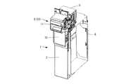
- FIG. 1 is an external perspective view showing a banknote recognition apparatus according to Embodiment 1 of the present invention.
- FIG. 2 is an external perspective view showing a state in which the front mask of the banknote recognition apparatus shown in FIG. 1 is removed.
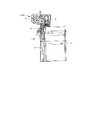
- FIG. 3 is a side sectional view showing the banknote recognition apparatus shown in FIG.
- FIG. 4 is a side sectional perspective view showing the banknote identification device shown in FIG.
- FIG. 5 is a perspective view showing a state in which the banknote guide of the banknote position guide mechanism of the banknote identification apparatus shown in FIG. 3 is open.
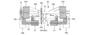
- 6A is a front view of the banknote position guide mechanism shown in FIG.
- FIG. 6B is a plan view of the banknote position guide mechanism shown in FIG.
- FIG. 6C is a rear view of the bill position guide mechanism shown in FIG.
- FIG. 7 is a perspective view showing a state in which the banknote guide of the banknote position guide mechanism shown in FIG. 5 is closed in the central direction of the banknote transport unit.
- FIG. 8A is a front view of the bill position guide mechanism shown in FIG.
- FIG. 8B is a plan view of the banknote position guide mechanism shown in FIG.
- FIG. 8C is a rear view of the bill position guide mechanism shown in FIG.
- FIG. 9 is a diagram showing the axial force (moving force in the longitudinal center direction of the driven shaft) of the moving side inclined gear of the bill position guide mechanism shown in FIG.
- FIG. 9 is a diagram showing the axial force (moving force in the longitudinal center direction of the driven shaft) of the moving side inclined gear of the bill position guide mechanism shown in FIG. FIG.
- FIG. 10 is a view showing a state in which a bill guide that is in contact with the movement-side oblique gear of the bill position guide mechanism shown in FIG.
- FIG. 11 is a diagram illustrating a state in which the moving side bevel gear and the bill guide illustrated in FIG. 10 start moving in the longitudinal center direction of the driven shaft.
- FIG. 12 is a diagram showing a state in which the moving side bevel gear and the bill guide shown in FIG. 11 have been moved in the longitudinal center direction of the driven shaft and are transporting bills.
- FIG. 13 is an external perspective view showing the banknote recognition apparatus according to the second embodiment of the present invention.
- FIG. 14 is a side sectional view showing the banknote identification device shown in FIG. FIG.
- FIG. 15 is a perspective view showing a state where the banknote guide of the banknote position guide mechanism of the banknote identification apparatus shown in FIG. 14 is open.
- FIG. 16A is a front view of the banknote position guide mechanism shown in FIG. 16B is a plan view of the banknote position guide mechanism shown in FIG.
- FIG. 16C is a rear view of the bill position guide mechanism shown in FIG. 15.
- FIG. 17 is a perspective view showing a state in which the banknote guide of the banknote position guide mechanism shown in FIG. 15 is closed in one direction of the banknote transport unit.
- 18A is a front view of the bill position guide mechanism shown in FIG. 18B is a plan view of the banknote position guide mechanism shown in FIG. 18C is a rear view of the bill position guide mechanism shown in FIG.
- FIG. 18A is a front view of the bill position guide mechanism shown in FIG. 18B is a plan view of the banknote position guide mechanism shown in FIG. 18C is a rear view of the bill position guide mechanism shown in FIG.
- FIG. 19 is a view showing a state in which a bill guide that is in contact with the movement side inclined gear of the bill position guide mechanism shown in FIG.
- FIG. 20 is a diagram illustrating a state in which the moving side inclined gear and the bill guide illustrated in FIG. 19 start moving in one direction of the driven shaft.
- FIG. 21 is a diagram illustrating a state in which the moving side bevel gear and the bill guide illustrated in FIG. 20 have been moved in one direction of the driven shaft and are transporting bills.
- FIG. 22 is an external perspective view showing the banknote recognition apparatus according to the third embodiment of the present invention.
- FIG. 23 is a side sectional view showing the banknote recognition apparatus shown in FIG. FIG.
- FIG. 24A is a perspective view of a state in which the bill guide of the bill position guide mechanism of the bill identifying apparatus shown in FIG.
- FIG. 24B is a rear perspective view of the banknote guide of the banknote position guide mechanism of the banknote recognition apparatus shown in FIG. 25A is a plan view of the banknote position guide mechanism shown in FIG.
- FIG. 25B is a front view of the banknote position guide mechanism shown in FIG.
- FIG. 25C is a rear view of the bill position guide mechanism shown in FIG.
- FIG. 26A is a perspective view of a state where the banknote guide of the banknote position guide mechanism shown in FIG. 24 is closed in the center direction of the banknote transport unit, as viewed obliquely from above.
- FIG. 24A is a perspective view of a state where the banknote guide of the banknote position guide mechanism shown in FIG. 24 is closed in the center direction of the banknote transport unit, as viewed obliquely from above.
- 26B is a rear perspective view of the banknote guide of the banknote position guide mechanism shown in FIG. 24 as viewed obliquely from below in the center direction of the banknote transport unit.
- 27A is a plan view of the bill position guide mechanism shown in FIG. 27B is a front view of the bill position guide mechanism shown in FIG.
- FIG. 27C is a rear view of the bill position guide mechanism shown in FIG.
- FIG. 28 is a diagram illustrating a state in which the banknote guide of the banknote position guide mechanism illustrated in FIG. 24 starts to move toward the center of the banknote transport unit.
- FIG. 29 is a diagram illustrating a state in which the banknote guide of the banknote position guide mechanism illustrated in FIG. 24 has completed the movement of the banknote transport unit in the center direction and is transporting banknotes.
- the banknote recognition apparatus of the first embodiment is configured to identify and store the authenticity of a plurality of types of banknotes having different widths such as euro banknotes and Chinese banknotes depending on denominations.
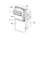
- FIG. 1 is an external perspective view showing a banknote identification device according to Embodiment 1 of the present invention
- FIG. 2 is an external perspective view showing a state where a front mask of the banknote identification device shown in FIG. 1 is removed.
- the banknote identification device 1 is composed of a main body frame section 2 and a banknote transport section 3 on the front side, a banknote identification section 5 and a banknote storage section 6 fixed behind the banknote identification section 5 and the banknote storage section 6. It is detachably mounted on the back surface of the part 2.
- a front mask 10 is disposed on the front upper portion of the main body frame portion 2. This front mask 10 has a bill insertion slot 11 formed in a passage width corresponding to the maximum width of the bill S to be inserted, and a bolt insertion groove 10a for fixing to the inside of the front door of the vending machine with a screw or the like. Is formed.
- a banknote transport unit 3 that transports the inserted banknote S to the banknote recognition unit 5 is disposed at the rear end of the banknote insertion slot 11.
- the banknote S inserted from the banknote insertion slot 11 of the front mask 10 is conveyed to the banknote identification part 5 by the banknote conveyance part 3, and the authenticity and denomination are identified by the identification sensor of the banknote identification part 5.
- the banknote S held in the banknote transport unit 3 passage is disposed below the banknote identification unit 5. It is conveyed to and stored in the bill storage unit 6.
- the banknote S in the banknote transport passage of the banknote transport unit 3 is sent back to the banknote insertion slot 11. Is done.
- FIG. 3 is a side sectional view showing the banknote recognition apparatus of FIG. 1
- FIG. 4 is a side sectional perspective view of FIG.
- the banknotes S to be identified and stored are banknotes having different dimensions (horizontal width) depending on the denomination. Therefore, the horizontal width of the banknote insertion slot 11 is set to 71 mm corresponding to, for example, a 10 yuan banknote or a 20 yuan banknote having a maximum horizontal width (70 mm) of a Chinese banknote. Moreover, the banknote conveyance part 3 is provided with the banknote position guide mechanism 30 by which the guide width is moved corresponding to the lateral width of the banknote inserted therein.
- the banknote transport unit 3 includes a plurality of transport rollers and a plurality of drive rollers that are rotationally driven by a banknote transport motor (not shown).
- an activation sensor (not shown) for detecting insertion of the inserted banknote S and activating a banknote transporting drive motor is disposed in the banknote transport unit 3 in the vicinity of the banknote insertion slot 11 and is predetermined in the banknote identification circuit. Is configured to send a signal.
- FIG. 5 is a perspective view showing a state where the banknote guide of the banknote position guide mechanism is open.
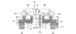
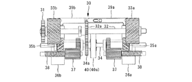
- 6A is a front view of the bill position guide mechanism shown in FIG. 6B is a plan view of the bill position guide mechanism shown in FIG. 6C is a back view of the bill position guide mechanism shown in FIG.
- FIG. 7 is a perspective view showing a state in which the banknote guide of the banknote position guide mechanism is closed in the central direction of the banknote transport unit.
- FIG. 8A is a front view of the bill position guide mechanism shown in FIG. 8B is a plan view of the bill position guide mechanism shown in FIG. 8C is a back view of the banknote position guide mechanism shown in FIG.
- FIG. 9 is a diagram showing the axial force (moving force toward the longitudinal center of the driven shaft) of the moving side bevel gear.
- the banknote position guide mechanism 30 is a pair of drive-side inclined teeth that are symmetrical with respect to the direction of the inclined teeth that are fixed and rotated by a drive shaft 32 that is rotationally driven by a drive motor (banknote conveying drive motor) via a drive gear 31.
- Gears 33a (left twisted direction), 33b (right twisted direction), and a drive shaft 32 rotated via a drive gear 32a and a driven gear 34a are provided so as to be movable in the longitudinal center direction of the driven shaft 34 that is driven and rotated.
- the movement-side inclined gears 35a (right twist direction), 35b (left-hand twist direction) and the movement-side inclined gears 35a, 35b are brought into contact with and linked to the movement of the bill S to be conveyed from the left and right.
- Banknote guides 36a and 36b that are sandwiched and guided toward the center of the banknote transport unit 3 are provided, and the moving side inclined gears 35a and 35b are engaged with the driving side inclined gears 33a and 33b, respectively.
- the pressure gear 37 meshed with the rotating gears 35aa and 35bb that are fixed to the moving side inclined gears 35a and 35b and rotates is the spring of the compression spring 38.
- a load (input) torque T is applied to the moving side bevel gears 35a, 35b by the surface pressure generated by being pressed against the left and right walls (not shown) by the pressure, an axial force is applied to the moving side bevel gears 35a, 35b.
- Fx moving force in the longitudinal center direction of the driven shaft 34
- the axial force Fx of the moving side bevel gears 35a and 35b is obtained by the following equation (see FIG. 9).
- T Load (input) torque (N ⁇ cm)
- d Reference pitch circle diameter (mm)
- ⁇ 30 °
- T 0.5 N ⁇ cm
- d 10 mm
- banknote guides 36a and 36b that sandwich the conveyed banknote S from the left and right are provided with left and right interlocking link devices 39a and 39b, and the banknote guides 36a and 36b that sandwich the banknote S to be transported from the left and right are symmetrical.
- the bill S is moved toward the longitudinal center of the driven shaft 34 with high accuracy.
- the banknote conveyance roller 41 is provided in a manner in contact with the longitudinal surface 40 a of the eccentric roller 40 provided on the driven shaft 34, and the banknote S is conveyed in cooperation with the banknote conveyance roller 41 by the rotation operation of the eccentric roller 40. (See FIG. 6A).
- FIG. 10 is a view showing a state in which a bill guide that is in contact with the movement side inclined gear of the bill position guide mechanism and interlocked with the movement is open.
- FIG. 11 is a figure which shows the state which a movement side inclined gear and a banknote guide start a movement to the longitudinal center direction of a driven shaft.
- FIG. 12 is a figure which shows the state which the movement side oblique gear and the banknote guide have completed the movement to the longitudinal center direction of a driven shaft, and are conveying the banknote.
- banknote guides 36 a and 36 b that are in contact with the movement-side bevel gears 35 a and 35 b of the banknote position guide mechanism 30 and interlock with the movement are provided. is open. And if the banknote S is inserted in the banknote insertion port 11, the banknote S in which the starting sensor (not shown) was inserted will be detected, and a predetermined signal will be sent to a banknote identification circuit.
- the drive shaft 32 When it is detected that the bill S has been inserted into the bill insertion slot 11, the drive shaft 32 is rotated counterclockwise (from the right in the figure) via the drive gear 31 by the drive motor as shown in FIG. It is driven to rotate.
- the driven shaft 34 When the drive shaft 32 is rotationally driven in the counterclockwise direction, the driven shaft 34 is also driven through the drive gear 32a and the driven gear 34a to rotate in the clockwise direction (viewed from the right in the figure).
- a pair of drive-side inclined gears 33a and 33b that are symmetrical with respect to the direction of the inclined tooth are respectively meshed with the moving-side inclined gears 35a and 35b that are movably provided in the longitudinal center direction of the driven shaft 34.
- Guidance is made so that the bill conveyance unit 3 is moved toward the center.
- the banknote S is transported in the direction toward the back of the banknote transport path in cooperation with the banknote transport roller 41 by the rotation operation of the eccentric roller 40 provided on the driven shaft 34.
- the eccentric roller 40 rotates and its short surface 40b faces the banknote transport roller 41, a gap is formed between the short surface 40b of the eccentric roller 40 and the banknote transport roller 41.
- the banknote S held by the banknote guides 36a and 36b is moved in the central direction of the banknote transport section 3 because the pressing force of the banknote S of the banknote transport roller 41 with respect to 40 is lost, and the banknote S is inclined in the transport direction. Is corrected (skew correction) and a centering operation for aligning the center of the banknote S with the center of the banknote transport unit 3 is performed.
- the pair of moving side bevel gears 35a, 35b stops moving in the central direction of the banknote transport unit 3 and performs only a rotating operation.
- the banknote S in which the inclination of the transport direction is corrected and the center of the banknote transport unit 3 is aligned is transported through the banknote transport path.
- the drive shaft 32 is rotated in the clockwise direction via the drive gear 31 (in the drawing, The banknotes S in the banknote transport passage of the banknote transport section 3 are rotated back to the banknote insertion slot 11 and returned to the banknote insertion slot 11.
- the banknote recognition device 1 that identifies and stores a plurality of types of banknotes S having different widths, and has a passage width corresponding to the maximum width of the banknotes S.
- the banknote transport unit 3 that transports the banknote S inserted into the banknote insertion slot 11 to the banknote recognition unit 5
- the banknote transport unit 3 is fixed to the drive shaft 32 and rotates.
- a pair of drive side inclined gears 33a, 33b that are symmetrical with each other, and a driven shaft 34 that is meshed with each of the pair of drive side inclined gears 33a, 33b and rotates when the drive shaft 32 rotates.
- the banknotes S that are brought into contact with the movement side bevel gears 35a and 35b and the pair of movement side bevel gears 35a and 35b that are movably provided in the longitudinal direction of the Banknotes are held from both sides
- the moving force (axial force Fx) of the moving side bevel gears 35a, 35b in the direction of the longitudinal center of the driven shaft 34 is moved by the surface pressure generated when the pressure gear 37 is pressed against the wall by the spring pressure.
- a load (input) torque T on the side bevel gears 35a and 35b even when a plurality of types of horizontal bills S are conveyed, the inclination in the conveying direction is corrected and the center of the conveying path is corrected. It becomes possible to provide the banknote identification device 1 that can be driven by a common drive source to transport the banknotes S together.
- banknote guides 36a and 36b which clamp the conveyed banknote S from the left and right move left and right symmetrically by the left and right interlocking link devices 39a and 39b, so that the banknote S to be transported is accurately brought to the center of the transport path. Is possible.
- the banknote conveyance roller 41 is provided in a manner in contact with the longitudinal surface 40 a of the eccentric roller 40 provided on the driven shaft 34, and the banknote S is conveyed in cooperation with the banknote conveyance roller 41 by the rotation operation of the eccentric roller 40.
- the banknote identification device 1 can be driven by a common driving source while correcting the inclination in the transport direction and transporting the center of the transport path with the center of the banknote S being aligned.
- the banknote S held by the banknote guides 36 a and 36 b is moved in the central direction of the banknote transport section 3 because the pressing force of the banknote S is lost.
- the banknote recognition device 1 that can correct the inclination in the transport direction and align the center of the banknote S with the center of the transport path.
- the rigidity of the banknote S held by the banknote guides 36a and 36b and the pair of moving side bevel gears 35a and 35b toward the center of the banknote transport unit 3 are moved.
- the pair of moving side bevel gears 35a and 35b can stop the movement of the banknote transport unit 3 in the center direction and perform only the rotating operation, thereby making a plurality of movements.
- the banknote recognition apparatus identifies and stores the authenticity of a plurality of types of banknotes such as euro banknotes and Chinese banknotes having different widths depending on the denomination. Is.
- FIG. 13 is an external perspective view showing the banknote recognition apparatus according to the second embodiment of the present invention.
- FIG. 14 is a side sectional view of the banknote recognition apparatus shown in FIG.
- the banknote recognition device 101 is composed of a main body frame section 102 and a banknote transport section 103 on the front side, a banknote identification section 105 and a banknote storage section 106 fixed behind the banknote identification section 105, and the banknote identification section 105 and the banknote storage section 106 are composed of a main body frame. It is detachably mounted on the back surface of the portion 102.
- a front mask 110 is disposed on the front upper portion of the main body frame portion 102.
- the front mask 110 has a bill insertion slot 111 formed with a passage width corresponding to the maximum width of the bill S to be inserted, and a bolt insertion groove 110a for fixing to the inside of the front door of the vending machine with a screw or the like. Is formed.
- a bill transport unit 103 that transports the inserted bill S to the bill recognition unit 105 is disposed at the rear end of the bill insertion slot 111.
- the banknote S inserted from the banknote insertion slot 111 of the front mask 110 is conveyed to the banknote identification part 105 by the banknote conveyance part 103, and the authenticity and denomination are identified by the identification sensor of the banknote identification part 105.
- the banknote S held in the banknote transport unit 103 passage is disposed below the banknote identification unit 105. It is conveyed to and stored in the bill storage unit 106.
- the banknote S in the banknote transport path of the banknote transport unit 103 is sent back to the banknote insertion slot 111. Is done.
- the banknote conveyance path inside the banknote recognition apparatus will be described.
- the banknote S to be identified and stored is a banknote having a different dimension (width) in the short direction depending on the denomination. Therefore, the horizontal width of the banknote insertion slot 111 is set to 71 mm, for example, corresponding to a 10 yuan banknote or a 20 yuan banknote having a maximum horizontal width (70 mm) of a Chinese banknote.
- the banknote conveyance part 103 is provided with the banknote position guide mechanism 130 by which the guide width is moved corresponding to the horizontal width of the banknote inserted therein.
- the banknote transport unit 103 includes a plurality of transport rollers and a plurality of drive rollers that are rotationally driven by a banknote transport drive motor (not shown).
- an activation sensor (not shown) for detecting the insertion of the inserted banknote S and activating the banknote transport motor is disposed in the banknote transport unit 103 in the vicinity of the banknote insertion slot 111, and the banknote identification circuit has a predetermined one. Is configured to send a signal.
- FIG. 15 is a perspective view showing a state in which the bill guide of the bill position guide mechanism is open.
- 16A is a front view of the banknote position guide mechanism shown in FIG.
- FIG. 16B is a plan view of the banknote position guide mechanism shown in FIG.
- FIG. 16C is a rear view of the bill position guide mechanism shown in FIG. 15.
- FIG. 17 is a perspective view showing a state where the banknote guide of the banknote position guide mechanism is closed in one direction of the banknote transport unit.
- 18A is a front view of the bill position guide mechanism shown in FIG.
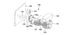
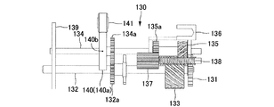
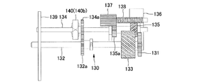
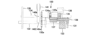
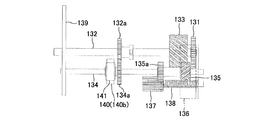
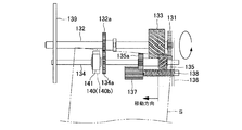
- the bill position guide mechanism 130 is driven by a drive side inclined gear 133 (right twist direction) fixed to a drive shaft 132 and rotated by a drive motor (banknote transport drive motor) via a drive gear 131.
- a drive side inclined gear 135 left twisted direction
- a moving side inclined gear 135 left twisted direction
- a moving side inclined tooth A bill guide 136 that contacts the gear 135 and interlocks with the movement of the gear 135 to sandwich the conveyed bill S and guide it in one direction (left direction in the figure) of the bill transport unit 103
- the tooth gear 135 is meshed with the drive-side bevel gear 133.
- the left end of the drive shaft 132 and the driven shaft 134 is arrange
- the pressure gear 137 meshed with the rotating gear 135a fixed to the moving side bevel gear 135 and rotated by the spring pressure of the compression spring 138 causes the right wall ( A load (input) torque T is applied to the moving side bevel gear 135 due to a surface pressure generated by being pressed against the moving side bevel gear 135 by an axial force Fx (in the longitudinal direction of the driven shaft 134). Movement force).
- the axial force Fx of the moving side bevel gear 135 is obtained by the following equation (see FIG. 9).
- T Load (input) torque (N ⁇ cm)
- d Reference pitch circle diameter (mm)
- ⁇ 30 °
- T 0.5 N ⁇ cm
- d 10 mm
- the banknote conveyance roller 141 is provided in a manner in contact with the longitudinal surface 140 a of the eccentric roller 140 provided on the driven shaft 134, and the banknote S is conveyed in cooperation with the banknote conveyance roller 141 by the rotation operation of the eccentric roller 140. (See FIG. 16A).
- the banknote S held by the banknote guide 136 moves in one direction (leftward in the figure) of the banknote transport unit 103 by eliminating the pressing force of the banknote S of the banknote transport roller 141 against the bank 140.
- the banknote S can be aligned in one direction of the transport path (in the figure, the banknote side wall 139 side) (see FIG. 18A).
- the rigidity of the banknote S held by the banknote guide 136 and the left side of the banknote transport unit 103 of the moving side bevel gear 135 are determined.
- the moving side bevel gear 135 stops moving the banknote transport unit 103 in the left direction and performs only the rotating operation.
- the bill position guide mechanism corrects the inclination of the bill conveyance direction (skew correction) and moves and aligns the bill S in one direction of the conveyance path (in the figure, the side wall 139 side). This will be described in detail with reference to FIG.
- FIG. 19 is a view showing a state in which a bill guide that is in contact with the movement-side oblique gear of the bill position guide mechanism and interlocked with the movement is open.
- FIG. 20 is a diagram illustrating a state in which the moving side bevel gear and the bill guide start moving in one direction of the driven shaft.
- FIG. 21 is a diagram illustrating a state in which the moving side bevel gear and the bill guide are transported in the bill after the movement of the driven shaft in one direction is completed.
- the banknote guide 136 that is in contact with the movement-side inclined gear 135 of the banknote position guide mechanism 130 and interlocked with the movement is open. And if the banknote S is inserted in the banknote insertion port 111, the banknote S in which the starting sensor (not shown) was inserted will be detected, and a predetermined signal will be sent to a banknote identification circuit.
- the drive shaft 132 When it is detected that the bill S has been inserted into the bill insertion slot 111, as shown in FIG. 20, the drive shaft 132 is rotated counterclockwise (from the right in the figure) via the drive gear 131 by the drive motor. It is driven to rotate. When the drive shaft 132 is rotationally driven in the counterclockwise direction, the driven shaft 134 is also driven through the drive gear 132a and the driven gear 134a to rotate in the clockwise direction (viewed from the right in the drawing).
- the moving side inclined gear 135 meshed with the driving side inclined gear 133 and movable in the longitudinal direction of the driven shaft 134 moves in the longitudinal direction (left direction in the figure) of the driven shaft 134.
- Force (axial force Fx) is generated, and the bill S 136 is sandwiched between the bills S taken in the bill transport passage (not shown) and is placed on the left side of the bill transport unit 103 (the bill side wall 139 side). Guide them to come.
- the bill S is transported in the direction toward the back of the bill transport path in cooperation with the bill transport roller 141 by the rotation operation of the eccentric roller 140 provided on the driven shaft 134.
- the eccentric roller 140 rotates and its short surface 140b faces the banknote transport roller 141, a gap is generated between the short surface 140b of the eccentric roller 140 and the banknote transport roller 141. Since the pressing force of the banknote S of the banknote transport roller 141 with respect to 140 disappears, the banknote S held by the banknote guide 136 moves in the left (in the figure, banknote side wall 39 side) direction of the banknote transport section 103. The movement of the banknote S is corrected (skew correction) and the banknote S is moved to the left side of the banknote transport unit 103 (in the figure, the banknote side wall 139 side).
- the rigidity of the banknote S held by the banknote guide 136 and the left side of the banknote transport unit 103 of the moving side bevel gear 135 are determined.
- the moving force (axial force Fx) in the direction (in the bill side wall 139 side in the figure) becomes equal, the moving side inclined gear 135 stops moving the bill conveying unit 103 in the left direction and rotates.
- the inclination in the transport direction is corrected, and the banknote S that is aligned with the left side of the banknote transport unit 103 is transported through the banknote transport path.
- the drive shaft 132 is rotated in the clockwise direction (in the drawing, The banknotes S in the banknote transport passage of the banknote transport section 103 are rotated back to the banknote insertion slot 111 and returned to the banknote insertion slot 111.
- the banknote recognition apparatus 101 that recognizes and stores a plurality of types of banknotes S having different widths is formed to have a passage width corresponding to the maximum width of the banknotes S.
- the banknote conveyance part 103 which conveys the banknote S inserted in the banknote insertion port 111 to the banknote identification part 105
- the banknote conveyance part 103 is fixed to the drive shaft 132, and the drive side diagonal. The movement which meshes with the toothed gear 133 and the drive-side bevel gear 133 and moves the driven shaft 134 which rotates following the rotation of the driving shaft 132 in one direction (left direction in the figure) of the bill transport unit 103.
- the moving force of the moving side bevel gear 135 is generated by applying a load torque to the moving side bevel gear 135 due to the surface pressure generated when the pressure gear 137 is pressed against the wall by the spring pressure.
- a bill recognition device that can be driven by a common drive source to correct the inclination in the transport direction and move the transport passage to a predetermined position in the transport passage. 101 can be provided.
- the banknote conveyance roller 141 is provided in a manner in contact with the longitudinal surface 140 a of the eccentric roller 140 provided on the driven shaft 134, and the banknote S is conveyed in cooperation with the banknote conveyance roller 141 by the rotation operation of the eccentric roller 140.
- the banknote recognition apparatus 101 can be driven by a common drive source while correcting the inclination in the transport direction and moving the transport path to a predetermined position in the transport path.
- the banknote recognition device 101 that can correct the inclination in the transport direction and can be moved to a predetermined position in the transport path.
- the moving side bevel gear 135 stops moving in one direction (in the left direction in the figure) of the bill conveyance unit 103 and only rotates.
- the banknote recognition apparatus identifies and determines the authenticity of multiple types of banknotes such as euro banknotes and Chinese banknotes having different widths depending on the denomination. It is to be stored.
- FIG. 22 is an external perspective view showing the banknote recognition apparatus according to the third embodiment of the present invention
- FIG. 23 is a side sectional view of the banknote identification apparatus shown in FIG.
- the banknote identification device 201 is composed of a main body frame section 202 and a banknote transport section 203 on the front side, a banknote identification section 205 and a banknote storage section 206 fixed to the back, and the banknote identification section 205 and the banknote storage section 206 are composed of a main body frame. It is detachably mounted on the back surface of the section 202.
- a front mask 210 is disposed on the front upper portion of the main body frame portion 202.
- the front mask 210 has a bill insertion slot 211 formed with a passage width corresponding to the maximum width of the bill S to be inserted, and a bolt insertion groove 210a for fixing to the inside of the front door of the vending machine with a screw or the like. Is formed.
- a bill transport unit 203 that transports the inserted bill S to the bill recognition unit 205 is disposed at the rear end of the bill insertion slot 211.
- the banknote S inserted from the banknote insertion slot 211 of the front mask 210 is conveyed to the banknote identification part 205 by the banknote conveyance part 203, and the authenticity and denomination are identified by the identification sensor of the banknote identification part 205.
- the banknote S held in the banknote transport unit 203 passage is disposed below the banknote identification unit 205. It is conveyed to and stored in the bill storage unit 206.
- the banknote S in the banknote transport passage of the banknote transport unit 203 is sent back to the banknote insertion slot 211. Is done.
- the banknote conveyance path inside the banknote recognition apparatus will be described.
- the horizontal width of the banknote insertion slot 211 is set to 71 mm corresponding to, for example, a 10-yuan banknote or a 20-yuan banknote having a maximum horizontal width (70 mm) of a Chinese banknote.
- the banknote conveyance part 203 is provided with the banknote position guide mechanism 230 by which the guide width
- the banknote transport unit 203 includes a plurality of transport rollers and a plurality of drive rollers that are rotationally driven by a banknote transport motor (not shown).
- an activation sensor (not shown) for detecting insertion of the inserted banknote S and activating the banknote transporting drive motor is disposed in the banknote transport unit 203 in the vicinity of the banknote insertion slot 211. Is configured to send a signal.
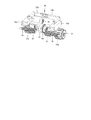
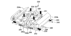
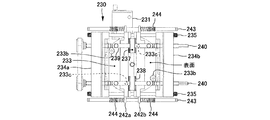
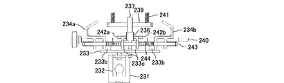
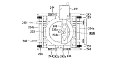
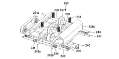
- FIG. 24A is a perspective view of a state in which the bill guide of the bill position guide mechanism of the bill identifying apparatus shown in FIG.
- FIG. 24B is a rear perspective view of the banknote guide of the banknote position guide mechanism of the banknote identification apparatus shown in FIG.
- FIG. 25A is a plan view of the bill position guide mechanism shown in FIG.
- FIG. 25B is a front view of the banknote position guide mechanism shown in FIG.
- FIG. 25C is a rear view of the bill position guide mechanism shown in FIG.
- FIG. 25A is a plan view of the bill position guide mechanism shown in FIG.
- FIG. 25B is a front view of the banknote position guide mechanism shown in FIG.
- FIG. 25C is a rear view of the bill position guide mechanism shown in FIG.
- FIG. 25A is a plan view of the bill position guide mechanism shown in FIG.
- FIG. 25B is a front view of the banknote position guide mechanism shown in FIG.
- FIG. 25C is a rear view of the bill position
- FIG. 26A is the perspective view which looked at the state which the banknote guide of the banknote position guidance mechanism has closed in the center direction of a banknote conveyance part from diagonally upward.
- FIG. 26B is a rear perspective view of a state in which the bill guide of the bill position guide mechanism is closed in the central direction of the bill transport unit, as viewed obliquely from below.
- 27A is a plan view of the bill position guide mechanism shown in FIG.
- FIG. 27B is a front view of the bill position guide mechanism shown in FIG.
- FIG. 27C is a rear view of the bill position guide mechanism shown in FIG.
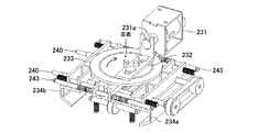
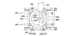
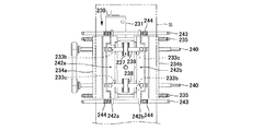
- the cam 233 has a cam pin (first cam pin) 233b and a cam pin (second cam pin) 233c on a surface (hereinafter referred to as a front surface) opposite to a surface (hereinafter referred to as a back surface) on which the cam pin 233a is disposed. Is arranged.
- a pair of banknote guides 234a for holding the banknote S to be conveyed from the left and right sides (the end face in the short direction of the banknote S) and guiding it in the center direction of the banknote transport section 203, 234b is inserted and arranged in the guide shaft 235, and the banknote guides 234a and 234b are arranged on the inner side corresponding to a 10 yuan banknote or a 20 yuan banknote having a maximum width (70 mm) of, for example, a Chinese banknote by a cam pin 233b at the time of banknote conveyance standby The width is pushed wide (see FIGS. 24 and 25).
- the banknote S being conveyed is sandwiched from the left and right sides (the end face in the short side direction of the banknote S) and the skew of the banknote S being guided in the center direction of the banknote transport section 203 is corrected and the centering of the banknote S is performed. (See FIGS. 26 and 27). Thereby, even if it is a case where the banknote S of multiple types of width is inserted from the banknote insertion port 211, while adjusting the inclination of a conveyance direction of any banknote S, the center of the banknote S is aligned with the center of a conveyance path. Thus, it is possible to provide a banknote recognition apparatus 201 that can be conveyed.
- banknote transport rollers 237 and 238 are inserted into the shafts 239 and 240 and are arranged so as to be movable in the left-right direction (short direction of the banknote S) with respect to the transport direction of the banknote S.
- the bill transport roller 237 is pressed against the bill transport roller 238 by the force of the spring 241 pressing the shaft 239 and the shaft 240 is driven to rotate, the bill transport roller 237 and the bill transport roller 238 cooperate with each other.
- the bill S is conveyed.
- a pair of movement restriction guides 242a and 242b are provided which are inserted into the shaft 243 and press the banknote transport rollers 237 and 238 from both sides by the return spring 244 at the time of banknote transport standby.
- the banknotes S being held and conveyed by the banknote guides 234a and 234b move in the central direction of the banknote transport section 203, thereby correcting the inclination of the transport direction and aligning the center of the banknotes with the center of the transport path. Can be provided.
- the banknote guides 234a and 234b sandwich the rigidity of the banknote S and the banknote S sandwiched from its left and right (end surfaces in the short direction of the banknote S).
- the bill guides 234a and 234b move in the center direction of the bill transport unit 203 by the force of the moving spring 236 pressing the bill guides 234a and 234b being pushed toward the center direction of the bill transport unit 203. To stop.
- the movement restriction guides 242a and 242b are moved inward by the force of the return spring 244, and the cam 233 is moved in the other direction (an arrow shown in FIG. 24B).
- the bill guides 234a and 234b and the bill transport rollers 237 and 238 return to the bill transport standby position, so that a plurality of types of horizontal bills are required without requiring a complicated mechanism or complicated bill position control. Even when the banknote is conveyed, it is possible to provide the banknote identification device 201 that can correct the inclination in the transport direction and transport the banknote S in the center of the transport path.
- FIG. 28 is a diagram illustrating a state in which the bill guide of the bill position guide mechanism starts moving toward the center of the bill transport unit.
- FIG. 29 is a figure which shows the state which the banknote guide of a banknote position guidance mechanism completes the movement to the center direction of a banknote conveyance part, and is conveying the banknote.
- the banknote guides 234a and 234b of the banknote position guide mechanism 230 are open as shown in FIG. And when the banknote S is inserted in the banknote insertion slot 211, the banknote S by which the starting sensor (not shown) was inserted is detected, a predetermined signal is sent to a banknote identification circuit, and banknote guides 234a and 234b are banknote conveyance parts. The movement starts toward the center 203.
- the movement restriction guides 242a and 242b are moved to the outside by the cam pins 233c provided on the cam 233 so that the bill transport rollers 237 and 238 are movable in the left and right direction (short direction of the bill S). Even when the banknotes S sandwiched and transported by 234a and 234b move in the center direction of the banknote transport section 203, the inclination of the banknote S in the transport direction is corrected and the center of the banknotes S is aligned with the center of the transport path.
- the bill transport roller 237 and the bill transport roller 238 cooperate to transport the bill S.
- the bill transport unit 237 and 238 are rotated in the reverse direction to drive the bill transport unit.
- the bill S in the bill transport passage 203 is sent back to the bill insertion slot 211 and returned.
- the third embodiment it is a banknote recognition device 201 that discriminates and stores a plurality of types of banknotes S having different widths, and has a passage width corresponding to the maximum width of the banknotes S.
- the banknote recognition apparatus 201 provided with the banknote conveyance part 203 which conveys the banknote S inserted in the banknote insertion slot 211 to the banknote identification part 205, the banknote S to convey is pinched
- any banknote S is corrected with the inclination in the transport direction and transported with the center of the banknote aligned with the center of the transport path. It becomes possible to provide the bill discriminating apparatus 201 that can be used.
- the banknote position guide mechanism 230 is disposed so as to be movable in the left-right direction with respect to the banknote S transport direction, and the banknote transport roller whose movement is restricted by a pair of movement restriction guides 242a and 242b during banknote transport standby.
- the cam 233 rotates in one direction, the movement restriction guides 242a and 242b are moved to the outside by cam pins (second cam pins) 233c provided on the cam 233, so that the bill transport rollers 237 and 238 are moved.
- the banknote guides 234a and 234b sandwich the banknote S sandwiched from the left and right and the banknote guides 234a and 234b sandwiching the banknote S are transferred to the banknote transport unit 203.
- the bill guides 234a and 234b stop moving in the center direction of the bill transport unit 203, so that a plurality of types of horizontal bills Even in the case of transporting S, it is possible to provide a banknote recognition device 201 that can correct the inclination in the transport direction and transport the banknote S while aligning the center of the transport path.
- the movement restriction guides 242a and 242b are moved inward by the force of the return spring 244 and the cam 233 is rotated in the other direction.
- the banknote guides 234a and 234b and the banknote transport rollers 237 and 238 return to the banknote transport standby position, a plurality of types of horizontal banknotes S are transported without requiring a complicated mechanism or complicated banknote position control.
Landscapes
- Engineering & Computer Science (AREA)
- Mechanical Engineering (AREA)
- Physics & Mathematics (AREA)
- General Physics & Mathematics (AREA)
- Registering Or Overturning Sheets (AREA)
- Inspection Of Paper Currency And Valuable Securities (AREA)
Abstract
Description
この実施の形態1の紙幣識別装置は、横幅が金種によって異なるユーロ紙幣や中国紙幣などの複数種類の横幅の紙幣の真贋を一台で識別判定して収納するものである。
Ft=20T/d
β:斜歯歯車のねじれ角(°)
T:負荷(入力)トルク(N・cm)
d:基準ピッチ円直径(mm)
例えば、β=30°、T=0.5N・cm、d=10mmとすると、軸方向力Fxには約0.6Nの力が発生する。
次に、実施の形態2について説明する。この実施の形態2の紙幣識別装置は、実施の形態1と同様に、横幅が金種によって異なるユーロ紙幣や中国紙幣などの複数種類の横幅の紙幣の真贋を一台で識別判定して収納するものである。
Ft=20T/d
β:斜歯歯車のねじれ角(°)
T:負荷(入力)トルク(N・cm)
d:基準ピッチ円直径(mm)
例えば、β=30°、T=0.5N・cm、d=10mmとすると、軸方向力Fxには約0.6Nの力が発生する。
次に、実施の形態3について説明する。この実施の形態3の紙幣識別装置は、実施の形態1,2と同様に、横幅が金種によって異なるユーロ紙幣や中国紙幣などの複数種類の横幅の紙幣の真贋を一台で識別判定して収納するものである。
2,102,202 本体フレーム部
3,103,203 紙幣搬送部
5,105,205 紙幣識別部
6,106,206 紙幣収納部
10,110,210 フロントマスク
11,111,211 紙幣挿入口
30,130,230 紙幣位置案内機構
31,131 駆動歯車
32,132 駆動軸
33a,33b,133 駆動側斜歯歯車
34,134 従動軸
35a,35b,135 移動側斜歯歯車
36a,36b,136,234a,234b 紙幣ガイド
37,137 加圧歯車
38,138 圧縮ばね
39a,39b 左右連動リンク装置
40,140 偏芯ローラ
40a,140a 偏芯ローラの長手面
40b,140b 偏芯ローラの短手面
41,141 紙幣搬送ローラ
231 ソレノイド(駆動手段)
233 カム
233b カムピン(第1のカムピン)
233c カムピン(第2のカムピン)
236 移動ばね
237,238 紙幣搬送ローラ
242a、242b 移動制限ガイド
244 復帰ばね
S 紙幣
Claims (15)
- 横幅の異なる複数種類の紙幣を識別判定して収納する紙幣識別装置であって、
前記紙幣の最大横幅に対応した通路幅に形成された紙幣挿入口に挿入された前記紙幣を紙幣識別部へと搬送する紙幣搬送部を備えた紙幣識別装置において、
前記紙幣搬送部は、駆動軸に固定されて回転する斜歯の方向を対称とする一対の駆動側斜歯歯車と、前記一対の駆動側斜歯歯車のそれぞれに噛み合わされて前記駆動軸が回転することに従動して回転する従動軸の長手中心方向に移動自在に設けられた移動側斜歯歯車と、前記一対の移動側斜歯歯車のそれぞれに当接してその移動に連動して前記搬送される紙幣をその左右から挟持して前記紙幣搬送部の中心方向に案内する紙幣ガイドとから構成される紙幣位置案内機構を有していることを特徴とする紙幣識別装置。 - 前記移動側斜歯歯車の前記従動軸の長手中心方向への移動力は、加圧歯車がばね圧により壁に押し付けられることで発生する面圧により前記移動側斜歯歯車に負荷トルクが加わることで発生することを特徴とする請求項1に記載の紙幣識別装置。
- 前記搬送される紙幣をその左右から挟持する前記紙幣ガイドは、左右連動リンク装置により左右対称に移動することを特徴とする請求項1に記載の紙幣識別装置。
- 前記従動軸に設けた偏芯ローラの長手面に当接する態様で紙幣搬送ローラを設け、前記偏芯ローラの回転動作により前記紙幣搬送ローラと協働して前記紙幣を搬送することを特徴とする請求項1に記載の紙幣識別装置。
- 前記偏芯ローラの短手面が前記紙幣搬送ローラに相対したときには前記紙幣の押え力が無くなることで前記紙幣ガイドが挟持している前記紙幣が前記紙幣搬送部の中心方向に移動することを特徴とする請求項4に記載の紙幣識別装置。
- 前記紙幣が前記紙幣搬送部の中心に移動すると、前記紙幣ガイドが挟持している前記紙幣の剛性と前記一対の移動側斜歯歯車の前記紙幣搬送部の中心方向への移動力とが相等しくなることで、前記一対の移動側斜歯歯車は前記紙幣搬送部の中心方向への移動を停止して回転動作のみを行うことを特徴とする請求項1または請求項5に記載の紙幣識別装置。
- 横幅の異なる複数種類の紙幣を識別判定して収納する紙幣識別装置であって、
前記紙幣の最大横幅に対応した通路幅に形成された紙幣挿入口に挿入された前記紙幣を紙幣識別部へと搬送する紙幣搬送部を備えた紙幣識別装置において、
前記紙幣搬送部は、駆動軸に固定されて回転する駆動側斜歯歯車と、前記駆動側斜歯歯車に噛み合わされて前記駆動軸が回転することに従動して回転する従動軸を前記紙幣搬送部の一方向に移動する移動側斜歯歯車と、前記移動側斜歯歯車に当接してその移動に連動して前記搬送される紙幣を挟持して前記紙幣搬送部の一方向に案内する紙幣ガイドとから構成される紙幣位置案内機構を有していることを特徴とする紙幣識別装置。 - 前記移動側斜歯歯車の移動力は、加圧歯車がばね圧により壁に押し付けられることで発生する面圧により前記移動側斜歯歯車に負荷トルクが加わることで発生することを特徴とする請求項7に記載の紙幣識別装置。
- 前記従動軸に設けた偏芯ローラの長手面に当接する態様で紙幣搬送ローラを設け、前記偏芯ローラの回転動作により前記紙幣搬送ローラと協働して前記紙幣を搬送することを特徴とする請求項7に記載の紙幣識別装置。
- 前記偏芯ローラの短手面が前記紙幣搬送ローラに相対したときには前記紙幣の押え力が無くなることで前記紙幣ガイドが挟持している前記紙幣が前記紙幣搬送部の一方向に移動することを特徴とする請求項9に記載の紙幣識別装置。
- 前記紙幣が前記紙幣搬送部の一方向に移動すると、前記紙幣ガイドが挟持している前記紙幣の剛性と前記移動側斜歯歯車の前記紙幣搬送部の一方向への移動力とが相等しくなることで、前記移動側斜歯歯車は前記紙幣搬送部の一方向への移動を停止して回転動作のみを行うことを特徴とする請求項7または請求項10に記載の紙幣識別装置。
- 横幅の異なる複数種類の紙幣を識別判定して収納する紙幣識別装置であって、
前記紙幣の最大横幅に対応した通路幅に形成された紙幣挿入口に挿入された前記紙幣を紙幣識別部へと搬送する紙幣搬送部を備えた紙幣識別装置において、
前記紙幣搬送部には搬送する前記紙幣をその左右から挟持して前記紙幣搬送部の中心方向に案内する一対の紙幣ガイドを有する紙幣位置案内機構が設けられ、該紙幣位置案内機構は、駆動手段によりカムが一方向に回転すると、該カムに設けられた第1のカムピンが前記紙幣ガイドから外れ、該第1のカムピンが外れた前記紙幣ガイドは、移動ばねの力で前記紙幣搬送部の中心方向へと移動し、搬送している前記紙幣をその左右から挟持して前記紙幣搬送部の中心方向に案内することを特徴とする紙幣識別装置。 - 前記紙幣位置案内機構には、前記紙幣の搬送方向に対してその左右方向に移動自在に配設され、紙幣搬送待機時には一対の移動制限ガイドにより移動が制限される紙幣搬送ローラを備え、前記カムが一方向に回転すると、該カムに設けられた第2のカムピンにより前記移動制限ガイドがその外側へと移動して前記紙幣搬送ローラがその左右方向に移動自在となり、前記紙幣ガイドが挟持して搬送している前記紙幣が前記紙幣搬送部の中心方向に移動することを特徴とする請求項12に記載の紙幣識別装置。
- 前記紙幣が前記紙幣搬送部の中心に移動すると、前記紙幣ガイドがその左右から挟持している前記紙幣の剛性と前記紙幣を挟持している前記紙幣ガイドを前記紙幣搬送部の中心方向へと押圧している前記移動ばねの力とが相等しくなることで、前記紙幣ガイドは前記紙幣搬送部の中心方向への移動を停止することを特徴とする請求項12または請求項13に記載の紙幣識別装置。
- 前記紙幣が前記紙幣位置案内機構から前記紙幣識別部へと搬送されると、前記移動制限ガイドは復帰ばねの力により内側へと移動して前記カムが他方向に回転し、前記紙幣ガイドおよび前記紙幣搬送ローラは紙幣搬送待機位置に戻ることを特徴とする請求項13に記載の紙幣識別装置。
Priority Applications (2)
| Application Number | Priority Date | Filing Date | Title |
|---|---|---|---|
| CN201580001492.9A CN105474277B (zh) | 2014-02-26 | 2015-02-25 | 纸币识别装置 |
| KR1020167002391A KR20160125941A (ko) | 2014-02-26 | 2015-02-25 | 지폐 식별 장치 |
Applications Claiming Priority (6)
| Application Number | Priority Date | Filing Date | Title |
|---|---|---|---|
| JP2014-035815 | 2014-02-26 | ||
| JP2014035815A JP2015162016A (ja) | 2014-02-26 | 2014-02-26 | 紙幣識別装置 |
| JP2014035816A JP6248699B2 (ja) | 2014-02-26 | 2014-02-26 | 紙幣識別装置 |
| JP2014-035816 | 2014-02-26 | ||
| JP2014047873A JP2015172818A (ja) | 2014-03-11 | 2014-03-11 | 紙幣識別装置 |
| JP2014-047873 | 2014-03-11 |
Publications (1)
| Publication Number | Publication Date |
|---|---|
| WO2015129746A1 true WO2015129746A1 (ja) | 2015-09-03 |
Family
ID=54009061
Family Applications (1)
| Application Number | Title | Priority Date | Filing Date |
|---|---|---|---|
| PCT/JP2015/055389 Ceased WO2015129746A1 (ja) | 2014-02-26 | 2015-02-25 | 紙幣識別装置 |
Country Status (3)
| Country | Link |
|---|---|
| KR (1) | KR20160125941A (ja) |
| CN (1) | CN105474277B (ja) |
| WO (1) | WO2015129746A1 (ja) |
Families Citing this family (1)
| Publication number | Priority date | Publication date | Assignee | Title |
|---|---|---|---|---|
| JP2020071707A (ja) * | 2018-10-31 | 2020-05-07 | 富士電機株式会社 | 硬貨検銭装置 |
Citations (3)
| Publication number | Priority date | Publication date | Assignee | Title |
|---|---|---|---|---|
| JPH0867376A (ja) * | 1994-08-30 | 1996-03-12 | Toyo Commun Equip Co Ltd | 紙葉類搬送装置に於ける幅寄せ機構 |
| JP2005115811A (ja) * | 2003-10-10 | 2005-04-28 | Japan Cash Machine Co Ltd | 有価紙葉鑑別装置 |
| JP2006248723A (ja) * | 2005-03-11 | 2006-09-21 | Ricoh Printing Systems Ltd | 画像形成装置 |
Family Cites Families (6)
| Publication number | Priority date | Publication date | Assignee | Title |
|---|---|---|---|---|
| EP1149362A1 (en) | 1999-02-02 | 2001-10-31 | Cashcode Company Inc. | Banknote centering device for a validator |
| JP3914807B2 (ja) * | 2001-09-11 | 2007-05-16 | 日立オムロンターミナルソリューションズ株式会社 | 紙幣入出金装置 |
| JP2005338990A (ja) | 2004-05-25 | 2005-12-08 | Matsushita Electric Ind Co Ltd | 紙幣識別装置 |
| JP5274999B2 (ja) * | 2007-12-12 | 2013-08-28 | 日立オムロンターミナルソリューションズ株式会社 | 紙幣取扱装置 |
| JP5184104B2 (ja) | 2008-01-11 | 2013-04-17 | 株式会社ユニバーサルエンターテインメント | 紙葉類処理装置 |
| CN102037498B (zh) * | 2008-06-27 | 2013-09-25 | 富士电机株式会社 | 纸币识别装置 |
-
2015
- 2015-02-25 KR KR1020167002391A patent/KR20160125941A/ko not_active Withdrawn
- 2015-02-25 CN CN201580001492.9A patent/CN105474277B/zh not_active Expired - Fee Related
- 2015-02-25 WO PCT/JP2015/055389 patent/WO2015129746A1/ja not_active Ceased
Patent Citations (3)
| Publication number | Priority date | Publication date | Assignee | Title |
|---|---|---|---|---|
| JPH0867376A (ja) * | 1994-08-30 | 1996-03-12 | Toyo Commun Equip Co Ltd | 紙葉類搬送装置に於ける幅寄せ機構 |
| JP2005115811A (ja) * | 2003-10-10 | 2005-04-28 | Japan Cash Machine Co Ltd | 有価紙葉鑑別装置 |
| JP2006248723A (ja) * | 2005-03-11 | 2006-09-21 | Ricoh Printing Systems Ltd | 画像形成装置 |
Also Published As
| Publication number | Publication date |
|---|---|
| KR20160125941A (ko) | 2016-11-01 |
| CN105474277B (zh) | 2018-06-12 |
| CN105474277A (zh) | 2016-04-06 |
Similar Documents
| Publication | Publication Date | Title |
|---|---|---|
| WO2009088090A1 (ja) | 紙葉類処理装置 | |
| CN101889297B (zh) | 纸币处理装置 | |
| CN111032545B (zh) | 摩擦运送装置以及纸张运送装置 | |
| JP5694785B2 (ja) | 紙葉類幅寄せ機構及び紙葉類幅寄せ方法 | |
| WO2015129746A1 (ja) | 紙幣識別装置 | |
| US7708273B2 (en) | Paper sheet processing apparatus | |
| JP5119530B2 (ja) | 紙幣識別収納装置の一時保留装置 | |
| JP6248699B2 (ja) | 紙幣識別装置 | |
| CN103548061B (zh) | 纸张类识别装置 | |
| JP2009134631A5 (ja) | ||
| JP2015162016A (ja) | 紙幣識別装置 | |
| WO2016000522A1 (zh) | 纸币清分机 | |
| JP2015172818A (ja) | 紙幣識別装置 | |
| JP2015099425A (ja) | 紙幣処理装置 | |
| JP6259525B2 (ja) | 搬送装置 | |
| JP6263363B2 (ja) | 紙幣処理装置 | |
| JP5091593B2 (ja) | 紙幣処理装置 | |
| KR20160018092A (ko) | 위폐감별기의 가이드장치 | |
| JP2023031462A (ja) | 紙幣整列機構及びこれを用いた紙幣識別装置 | |
| JP2015172819A (ja) | 紙幣識別装置 | |
| JPWO2019016964A1 (ja) | 紙葉類搬送装置、紙葉類取扱装置及び紙葉類搬送方法 | |
| JP5079353B2 (ja) | 紙幣識別装置 | |
| JP2016031665A (ja) | 貨幣交換装置および貨幣パック | |
| JP5889711B2 (ja) | 紙幣処理装置 | |
| JP2007220031A (ja) | 紙幣取扱装置 |
Legal Events
| Date | Code | Title | Description |
|---|---|---|---|
| WWE | Wipo information: entry into national phase |
Ref document number: 201580001492.9 Country of ref document: CN |
|
| 121 | Ep: the epo has been informed by wipo that ep was designated in this application |
Ref document number: 15755953 Country of ref document: EP Kind code of ref document: A1 |
|
| ENP | Entry into the national phase |
Ref document number: 20167002391 Country of ref document: KR Kind code of ref document: A |
|
| NENP | Non-entry into the national phase |
Ref country code: DE |
|
| 122 | Ep: pct application non-entry in european phase |
Ref document number: 15755953 Country of ref document: EP Kind code of ref document: A1 |