WO2015129441A1 - 集塵装置、及び電気掃除機 - Google Patents
集塵装置、及び電気掃除機 Download PDFInfo
- Publication number
- WO2015129441A1 WO2015129441A1 PCT/JP2015/053512 JP2015053512W WO2015129441A1 WO 2015129441 A1 WO2015129441 A1 WO 2015129441A1 JP 2015053512 W JP2015053512 W JP 2015053512W WO 2015129441 A1 WO2015129441 A1 WO 2015129441A1
- Authority
- WO
- WIPO (PCT)
- Prior art keywords
- dust
- centrifuge
- centrifugal separator
- air
- collecting
- Prior art date
- Legal status (The legal status is an assumption and is not a legal conclusion. Google has not performed a legal analysis and makes no representation as to the accuracy of the status listed.)
- Ceased
Links
Images



Classifications
-
- A—HUMAN NECESSITIES
- A47—FURNITURE; DOMESTIC ARTICLES OR APPLIANCES; COFFEE MILLS; SPICE MILLS; SUCTION CLEANERS IN GENERAL
- A47L—DOMESTIC WASHING OR CLEANING; SUCTION CLEANERS IN GENERAL
- A47L9/00—Details or accessories of suction cleaners, e.g. mechanical means for controlling the suction or for effecting pulsating action; Storing devices specially adapted to suction cleaners or parts thereof; Carrying-vehicles specially adapted for suction cleaners
- A47L9/10—Filters; Dust separators; Dust removal; Automatic exchange of filters
- A47L9/16—Arrangement or disposition of cyclones or other devices with centrifugal action
- A47L9/1683—Dust collecting chambers; Dust collecting receptacles
-
- A—HUMAN NECESSITIES
- A47—FURNITURE; DOMESTIC ARTICLES OR APPLIANCES; COFFEE MILLS; SPICE MILLS; SUCTION CLEANERS IN GENERAL
- A47L—DOMESTIC WASHING OR CLEANING; SUCTION CLEANERS IN GENERAL
- A47L9/00—Details or accessories of suction cleaners, e.g. mechanical means for controlling the suction or for effecting pulsating action; Storing devices specially adapted to suction cleaners or parts thereof; Carrying-vehicles specially adapted for suction cleaners
- A47L9/10—Filters; Dust separators; Dust removal; Automatic exchange of filters
- A47L9/16—Arrangement or disposition of cyclones or other devices with centrifugal action
- A47L9/1616—Multiple arrangement thereof
- A47L9/1625—Multiple arrangement thereof for series flow
- A47L9/1633—Concentric cyclones
-
- A—HUMAN NECESSITIES
- A47—FURNITURE; DOMESTIC ARTICLES OR APPLIANCES; COFFEE MILLS; SPICE MILLS; SUCTION CLEANERS IN GENERAL
- A47L—DOMESTIC WASHING OR CLEANING; SUCTION CLEANERS IN GENERAL
- A47L9/00—Details or accessories of suction cleaners, e.g. mechanical means for controlling the suction or for effecting pulsating action; Storing devices specially adapted to suction cleaners or parts thereof; Carrying-vehicles specially adapted for suction cleaners
- A47L9/10—Filters; Dust separators; Dust removal; Automatic exchange of filters
- A47L9/16—Arrangement or disposition of cyclones or other devices with centrifugal action
- A47L9/1616—Multiple arrangement thereof
- A47L9/1641—Multiple arrangement thereof for parallel flow
Definitions
- the present invention relates to a dust collector and a vacuum cleaner.
- a so-called cyclonic electric vacuum cleaner equipped with a cyclone type dust collecting device that centrifuges dust by swirling sucked air in a dust collecting container is known.
- a cyclone type dust collector is provided with a filter for further filtering the air after the dust is centrifuged. As a result, fine dust that has not been centrifuged is collected by the filter.
- multi-cyclone vacuum cleaners that are provided with two stages of centrifugal separators for swirling air and that are designed so that the size of the dust that is centrifuged in each centrifugal separator is different.
- Such a multi-cyclone type vacuum cleaner is disclosed in Patent Document 1, for example.
- JP 2013-236671 A (published on November 28, 2013)
- the coarse dust separated by the first centrifugal separator is stored in the bottom lid of the case part.
- the fine dust separated by the second centrifugal separator is stored in a fine dust reservoir that communicates with the lower end of the second centrifugal separator.
- the fine dust reservoir portion is provided in an annular shape, and extends upward with respect to the case portion continuously to the entire peripheral edge portion of the upper end portion of the case portion of the first centrifugal separation portion.
- the open / close lid part of the fine dust reservoir is opened and closed in conjunction with the opening and closing of the lower part of the first centrifugal separation part (case part) by the bottom cover.
- the user opens the bottom lid of the case portion to discard the coarse dust, and the fine dust accumulated in the fine dust reservoir portion is also moved to the first centrifugal separation portion side only by this operation.
- Guide and dispose of together with the coarse dust Therefore, in the dust collector of Patent Document 1, in order to dispose of the fine dust collected in the fine dust reservoir together with the coarse dust, the open / close lid portion of the fine dust reservoir is linked to the opening / closing of the bottom lid. A structure for opening and closing is required, and the structure of the apparatus becomes complicated.
- the air path first extends upward from the second centrifugal separator and is bent to the side of the second centrifugal separator in the middle. That is, since the air passage in the dust collector is bent in this way, the pressure loss in the air passage increases, and the suction power of the cleaner decreases.
- the exhaust air passage communicates with the downstream side of the second centrifugal separator, and the flow rate of air from above the second centrifugal separator to the side of the second centrifugal separator. It is continuous and narrows backward. As described above, since there is a portion where the width is narrowed in the air passage, in the vacuum cleaner described in Patent Document 1, turning noise and wind noise increase. Furthermore, the structure of the exhaust air passage is complicated.
- the present invention has been made in view of the above-described conventional problems.
- the first object of the present invention is to separate fine dust separated by the second centrifugal separator and the first centrifugal separator by a simple structure.
- An object of the present invention is to provide a dust collector and a vacuum cleaner that can dispose of coarse dust together.
- the present invention has been made in view of the above-described conventional problems, and a second object thereof is a dust collector capable of suppressing an increase in pressure loss in an air passage, and a vacuum cleaner. Is to provide.
- a dust collector communicates with a first centrifugal separation unit that separates first dust in dust-containing air, and the first centrifugal separation unit.
- a second centrifuge for separating second dust smaller than the first dust in the dust-containing air that has passed through the first centrifuge, and collecting the first and second dust.
- a dust collecting container for collecting dust, the dust collecting container being divided into a first dust collecting chamber for collecting the first dust and a second dust collecting chamber for collecting the second dust.
- a part of the wall surface constituting the second dust collection chamber is an outer peripheral surface of the first dust collection chamber.
- the dust collector which concerns on 1 aspect of this invention is the 1st centrifuge part which isolate
- a second centrifuge unit that separates second dust that is smaller than the first dust in the dust-containing air that has been provided in the upper stage and has passed through the first centrifuge unit, and the first and first A dust collecting device that collects the dust of the second dust, and is provided with a discharge port for discharging the air from which the first and second dusts are separated.
- the exhaust air passage from the air outlet to the exhaust port in the centrifugal separator is provided above the second centrifugal separator.
- FIG. 1 It is a perspective view which shows the structure of the vacuum cleaner main body with which the vacuum cleaner which concerns on embodiment of this invention was equipped. It is sectional drawing which shows the structure of the cleaner body shown in FIG. It is a perspective view which shows the structure of the dust collector which concerns on embodiment of this invention. It is a disassembled perspective view which shows the structure of the dust collector which concerns on embodiment of this invention. It is sectional drawing for demonstrating the flow of the air in the dust collector which concerns on embodiment of this invention. It is sectional drawing which shows the structure of the dust collector which concerns on embodiment of this invention. It is a disassembled perspective view which shows the structure of the dust collection part main body in the dust collector which concerns on embodiment of this invention. It is a disassembled perspective view which shows the structure of the 2nd centrifuge unit in the dust collector which concerns on embodiment of this invention. It is a disassembled perspective view which shows the structure of the filter unit in the dust collector which concerns on embodiment of this invention.
- Embodiment 1 (Vacuum cleaner body)
- Embodiment 1 of the present invention will be described in detail.
- the vacuum cleaner according to the present embodiment has a configuration including a vacuum cleaner body, a suction port, a connection pipe, a connection hose, an operation handle, and the like.
- FIG. 1 is a perspective view showing a configuration of a vacuum cleaner body 1 provided in the electric vacuum cleaner according to the present embodiment.
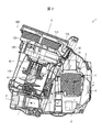
- FIG. 2 is a cross-sectional view showing the configuration of the cleaner body 1.
- the cleaner body 1 includes a drive device 2 and a cyclone dust collector 100.
- the drive device 2 supports the dust collector 100 in a detachable manner in the front.
- the surface on which the cleaner body 1 is installed is a horizontal surface.
- a direction perpendicular to the horizontal plane is defined as a height direction.
- the opposite side to the drive device 2 in the dust collector 100 be a front side, and let the opposite side to this front side be a rear side.
- the driving device 2 includes a connecting portion 3, an external exhaust port 4 for discharging internal air to the outside, an electric blower 5, and a control device 6.
- a connection hose provided in the vacuum cleaner according to the present embodiment is connected to the connection unit 3.
- the drive device 2 has an exhaust port 31 and an intake port 32.
- the electric blower 5 has a blower fan for performing intake air and a blower drive motor that rotationally drives the blower fan.
- the control device 6 has a control unit such as a CPU, a RAM, and a ROM, and comprehensively controls the electric vacuum cleaner. Specifically, in the control device 6, the CPU executes various processes according to a control program stored in the ROM.
- the electric blower 5 built in the cleaner main body 1 is operated, whereby intake is performed from the suction port portion.
- the air containing dust sucked from the suction port portion passes through the suction path Y indicated by the broken-line arrow from the connection portion 3 to the dust collecting device 100 from the exhaust port 31 of the driving device 2. be introduced.
- the air sucked in the dust collector 100 is sucked from the air inlet 32 of the drive device 2 in a state where the dust is centrifuged and the dust is removed.
- the air sucked from the intake port 32 is discharged to the outside from the external exhaust port 4 provided at the rear portion of the drive device 2 through the exhaust path Z indicated by the solid line arrow.
- the exhaust path Z passes through the control device 6. For this reason, the control device 6 is cooled by the air flowing through the exhaust path Z.
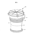
- FIG. 3 is a perspective view showing the configuration of the dust collector 100.
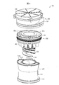
- FIG. 4 is an exploded perspective view showing the configuration of the dust collector 100.
- FIG. 5 is a cross-sectional view for explaining the flow of air in the dust collector 100.
- FIG. 6 is a cross-sectional view showing the configuration of the dust collector 100. 5 and 6, the cross-sectional direction of the dust collector 100 is different.
- the dust collector 100 is mounted on the driving device 2 and constitutes the cleaner body 1, and the central axis C is about 20 ° with respect to the horizontal plane. It is arranged to incline to.
- the height and front-rear direction dimensions of the cleaner body 1 can be reduced, and a compact design of the cleaner body 1 becomes possible.
- the dust collector 100 is tilted so that the central axis C exceeds 30 ° with respect to the horizontal plane, the height dimension can be suppressed, but the front-back dimension increases.
- the cleaner main body 1 can be designed in a compact manner by inclining the central axis C of the dust collector 100 around 20 ° with respect to the horizontal plane.
- the dust collector 100 includes a dust collector main body 110, a second centrifuge unit 120, and a filter unit 130.
- the dust collection unit main body 110 includes a dust collection cup 111 having an upper opening.
- the second centrifuge unit 120 is detachably attached to the upper opening of the dust collection cup 111.
- the filter unit 130 is attached to the upper part of the second centrifuge unit 120.
- the dust collection unit main body 110 includes a dust collection cup 111 in which an inflow port 113 for introducing air containing dust is formed.
- the dust collection cup 111 is open at the top and is divided into a first dust collection chamber 111A and a second dust collection chamber 111B formed around the first dust collection chamber 111A.
- the second dust collection chamber 111B is configured such that its inner wall includes the outer peripheral surface 111C of the first dust collection chamber 111A.
- the lower part (bottom) of the dust collection cup 111 is also opened.
- a bottom cover 114 is provided at the bottom of the dust collection cup 111 so as to be openable and closable. Since the second dust collection chamber 111B is provided on the outer periphery of the first dust collection chamber 111A, the dust collection cup 111 can be easily washed with water, and maintenance is facilitated.
- FIG. 7 is an exploded perspective view showing the configuration of the dust collector main body 110. With reference to FIG. 7, the configuration of the bottom cover 114 will be described in detail.
- the bottom lid 114 is rotatably attached to the dust collection cup 111 via a shaft portion (not shown) supported by the shaft support portion 112 so that the bottom lid 114 can be opened and closed with respect to the dust collection cup 111.
- An opening 114 a is formed in the center portion of the bottom lid 114.
- the bottom cover 114 is provided with a rotation transmission mechanism 50 (first rotation transmission mechanism).
- the rotation transmission mechanism 50 is rotatably provided in the opening 114a of the bottom cover 114.
- the opening 114a has a cylindrical shape protruding upward.
- a receiving portion 114b that functions as a bearing of the rotation transmission mechanism 50 (first rotation transmission mechanism) is integrally provided on the inner surface of the opening 114a.
- the receiving part 114b has a cylindrical shape as shown in FIGS.
- a support portion 51 is rotatably provided below the receiving portion 114b.
- the support portion 51 has an opening that substantially matches the inner diameter of the cylinder of the receiving portion 114b, and is formed with a league-shaped recess that fits into the receiving portion 114b.
- a transmission gear 52 for transmitting rotation is provided via a coil spring 53 below the support portion 51.
- An annular lower seal material 54 is provided to seal between the lower surface of the bottom lid 114 and the transmission gear 52.
- the lower seal material 54 is fitted and fixed between the opening 114 a and the receiving portion 114 b of the bottom lid 114, and the lower surface is in close contact with the transmission gear 52.
- the upper portion of the coil spring 53 is in contact with a flange portion 51 a formed on the outer periphery of the support portion 51.
- the lower portion of the coil spring 53 is fitted into an annular hole 52a formed in an annular shape in the transmission gear 52, and is in contact with the bottom surface of the annular hole 52a.
- the coil spring 53 is interposed between the support portion 51 and the transmission gear 52.
- the transmission gear 52 is urged downward by the action of the urging force of the coil spring 53.
- a connecting part 55 is provided in the opening part 114a via an upper sealing material 56.
- the connecting portion 55 is for transmitting the rotational force that is the driving force of the transmission gear 52 to the rotation transmission mechanism 60 that rotates the compression portion 123 of the second centrifugal separation unit 120.
- the connecting portion 55 is integrally provided with a ring-shaped flange portion 55a at a substantially central portion in the vertical direction (height direction).
- the upper seal material 56 is fitted and fixed to the flange portion 55a.
- the outer peripheral surface of the upper seal material 56 comes into contact with the opening 114 a and seals the dust collection space inside the dust collection cup 111.
- the upper surface of the upper seal material 56 is provided in an exposed state in the dust collection cup 111, and a lower end of a compression portion constituting a second rotation transmission mechanism described later comes into contact with the member. Has the function of sealing.
- the connecting portion 55 is provided with a connecting body 55b that protrudes upward from the flange portion 55a and a shaft portion 55c that protrudes downward from the flange portion 55a.
- the connection body 55b is provided to connect to the rotation transmission mechanism 60 that rotates the compression unit 123 of the second centrifuge unit 120.
- the shaft portion 55c passes through the opening of the receiving portion 114b of the opening portion 114a.
- a portion of the shaft portion 55c corresponding to the opening of the receiving portion 114b has a cylindrical shape, and a lower portion thereof has a quadrangular prism shape. And the four protrusion part protruded from each surface of the said square pole shape is provided.
- An opening is formed in the support portion 51 so as to match the lower shape of the shaft portion 55c.
- the transmission gear 52 is formed with a coupling portion 52b that engages with the lower shape of the shaft portion 55c.
- the coupling portion 52b has an opening that matches the lower shape of the shaft portion 55c. Therefore, the transmission gear 52 is screw-fixed by fastening the central portion of the connecting portion 55 with the fixing screw 57A and the nut 57B with the coil spring 53 interposed therebetween. And it connects rotatably via the receiving part 114b of the opening part 114a of the bottom cover 114. As shown in FIG.
- the transmission gear 52 is provided on the bottom surface of the dust collector 100, that is, on the bottom lid 114 of the dust collection cup 111.
- the inside of the dust collection cup 111 is sealed with an upper sealing material 56 and a lower 54.
- annular sealing material 58 is attached to the lower surface of the collar portion of the dust collection cup 111.
- the annular sealing material 58 maintains the hermetic sealing between the openable / closable bottom lid 114 and the dust collecting cup 111.
- a transmission drive gear constituting a drive unit serving as a drive source is provided on the drive device 2 side.
- the transmission drive gear is configured to mesh with the transmission gear 52.
- FIG. 8 is an exploded perspective view showing the configuration of the second centrifuge unit 120.
- the second centrifuge unit 120 includes an upper lid body 121 that closes the dust collection cup 111 from above, an inner cylinder portion 122, a compression portion 123, and a rotation transmission mechanism 60. (Second rotation transmission mechanism).
- an opening 121a is formed in the center of the upper surface of the upper lid body 121.
- the upper cover main body 121 has the cylindrical part 121b in the upper part.
- a connecting projection 121c is formed at the lowermost portion of the upper lid body 121, and a tapered portion 121d is connected to the connecting projection 121c.
- the upper lid body 121 is detachably attached to the dust collection cup 111. For this reason, the dust collector 100 can be easily disassembled, and maintenance becomes easy.
- the second centrifuges 80 are arranged side by side along the inner surface constituting the cylindrical part 121b of the upper lid body 121.
- an inflow port 81 is formed so as to communicate with the space in the cylindrical part 121b.
- the second centrifugal separation unit 80 includes a swivel cylinder portion 82 in which air flowing in from the inflow port 81 swirls.
- the swivel cylinder portion 82 has a tapered structure configured to become narrower downward.
- An exhaust cylinder 83 is provided so as to extend downward from the outlet 83a. The air separated by the second centrifugal separator 80 passes through the exhaust pipe 83 and is discharged upward from the outlet 83a provided in the upper part.
- a flat surface that is flush with the upper surface of the second centrifuge 80 is formed on the upper portion of the upper lid body 121. For this reason, the upper part of the upper lid body 121 can be easily cleaned, and maintenance of the dust collector 100 is facilitated.
- Each second centrifuge 80 has a structure protruding vertically downward from the upper lid body 121.
- the second centrifuge unit 120 is attached to the dust collection unit main body 110
- the lower part of each second centrifuge unit 80 is accommodated in the second dust collection chamber 111 ⁇ / b> B of the dust collection cup 111.
- the second dust collection chamber 111B of the dust collection cup 111 is provided with a space for accommodating the swivel cylinder portion 82 in the lower portion of each second centrifugal separator 80. Accordingly, the height of the dust collector 100 can be reduced by the amount that the second centrifugal separator 80 is accommodated in the second dust collection chamber 111B.
- a taper wall surface adapted to the taper structure of the swivel cylinder portion 82 of the second centrifugal separator 80 is formed in a space in the second dust collecting chamber 111B in which the second centrifugal separators 80 are accommodated. Thereby, each second centrifuge 80 can be stably held in the second dust collecting chamber 111B.
- all the openings at the lower end of the second centrifugal separator 80 are arranged so as to communicate with the second dust collecting chamber 111B. And in the state where the 2nd centrifuge unit 120 was attached to dust collection part main part 110, the lower end part of the 2nd centrifuge part 80 comes to be positioned by the wall surface which constitutes the 2nd dust collection room 111B. Yes.
- the inner cylinder part 122 is connected to the lower part of the upper lid body 121, and is configured to vent the air after the cyclone separation by the first centrifugal separator described later to the upper part of the upper lid body 121.
- the compressing unit 123 is for compressing the dust collected in the dust collecting cup 111.
- the rotation transmission mechanism 60 is for transmitting the rotational force of the rotation transmission mechanism 50 to the compression unit 123.
- the inner cylinder part 122 has an upper opening edge 122a that expands upward, and a body part 122c having a plurality of slits 122b for allowing air after centrifugation to pass through. Note that a mesh-shaped intake-side filter is wound around the outer periphery of the body portion 122c.
- the upper opening edge 122a of the inner cylinder part 122 is joined to the taper part 121d of the upper lid body 121 with a screw.
- a sealing material (not shown) is fixed to the upper edge of the upper opening edge 122a of the inner cylinder portion 122 in advance. The space between the upper edge of the upper opening edge 122a and the lower surface of the tapered portion 121d of the upper lid body 121 is sealed with this sealing material.
- a seal member 124 is provided at the lower end of the body portion 122 c of the inner cylinder portion 122.
- the compression part 123 has a large-diameter cylindrical part 123a at the top.
- a small diameter cylindrical portion 123b having a diameter smaller than that of the large diameter cylindrical portion 123a is provided below the large diameter cylindrical portion 123a.
- the large-diameter cylindrical portion 123a communicates with the inner cylindrical portion 122, and has a function of classifying the upper portion of the dust collection cup 111 as a centrifugal separation portion (cyclone portion) and the lower portion as a dust collection portion that collects dust after separation. Prepare. For this reason, the diameter of the large diameter cylindrical portion 123 a is larger than the cylindrical diameter of the inner cylindrical portion 122.
- the compression part 123 has a spiral blade 123c doubled on its outer peripheral surface over the large diameter cylindrical part 123a and the small diameter cylindrical part 123b.
- Each spiral blade 123c has a function of compressing dust and dust in the dust collection cup 111 by rotating.
- a plurality of small protrusions 123d are formed on the lower surface of the spiral blade 123c. These protrusions 123d have a function of contacting and pushing down the dust and dust when the spiral blades 123c rotate, and this function can increase the compressibility of the dust and dust.
- the lower end of the small diameter cylindrical portion 123b of the compression portion 123 is in close contact with the upper sealing material 56 provided on the bottom lid 114 as shown in FIG.
- the sealing by the upper sealing material 56 can prevent the dust in the dust collection cup 111 and the dust in the compression portion 123 from being mixed.
- the rotation transmission mechanism 60 includes an engaging portion 61, a first rotating cylinder 62, and a second rotating cylinder 63.
- the engaging portion 61 is integrally formed inside the small diameter cylindrical portion 123 b of the compression portion 123, and is engaged and connected to the connecting portion 55 of the rotation transmission mechanism 50.
- the engagement / connection between the connecting portion 55 and the engaging portion 61 is not particularly limited, and a conventionally known connecting mechanism can be used to connect the drive.
- the compression portion 123 is provided with a connecting piece 123 e having a flat shape.
- the connecting piece 123e is configured such that the large-diameter cylindrical portion 123a and the small-diameter cylindrical portion 123b are vertically connected.
- the first rotating cylinder 62 and the second rotating cylinder 63 are supported and fixed to the connecting piece 123e.
- the first rotating cylinder 62 and the second rotating cylinder 63 are housed in the inner cylinder portion 122.
- the second rotating cylinder 63 is fixed with screws 64 (see FIG. 5).
- the cylinder inner diameter of the second rotating cylinder 63 is substantially the same as the inner cylinder inner diameter of the small diameter cylindrical portion 123b.
- the second rotating cylinder 63 is formed so that the inner diameter of the cylinder is substantially the same as the inner diameter of the first rotating cylinder 62.
- the first rotating cylinder 62 is provided in the inner cylinder portion 122 so as to be rotatable.
- a support portion 62 a that protrudes outward is integrally formed at the upper end of the first rotating cylinder 62.
- the support portion 62 a is held (supported) on the upper opening edge 122 a of the inner cylinder portion 122.
- the support portion 62 a is supported by being sandwiched between the lower end of the connection projecting portion 121 c of the upper lid body 121 and the upper opening edge 124 a.
- the first rotating cylinder 62 is rotatably supported by the inner cylinder portion 122.
- the first rotating cylinder 62 and the second rotating cylinder 63 have substantially the same structure as the inner cylinder part 122, and a slit is formed in the cylindrical body part. Thereby, air can be ventilated between the inside and the outside of the first rotating cylinder 62 and the second rotating cylinder 63.
- the first rotating cylinder 62 is integrally provided with four connecting pieces 62b protruding upward.
- the connecting piece 62b is formed inward of the support portion 62a and inward of the connecting protrusion 121c of the upper lid body 121.
- the upper lid main body 121 is provided with a locking piece that protrudes downward.
- This locking piece is provided so as to be locked to the connecting piece 62b of the first rotating cylinder 62, and locks at least two connecting pieces 62b.
- FIG. 9 is an exploded perspective view showing the configuration of the filter unit 130.
- the filter unit 130 includes a filter case 131, an exhaust-side filter 132, a sealing material 133, and a filter cover 134.
- the filter case 131 supports the lower part of the exhaust side filter 132.
- the exhaust side filter 132 is detachably accommodated in the filter case 131.
- the filter cover 134 is detachably attached to the filter case 131 and is configured to cover the upper part of the exhaust-side filter 132.
- a sealing material 133 is attached to the outer periphery of the exhaust side filter 132. The sealing material 133 is used to bring the exhaust filter 132 and the filter cover 134 into close contact with each other.
- the exhaust-side filter 132 includes a filter main body 132a made of a folded HEPA filter, an annular frame 132b for holding the filter main body 132a, a central boss portion 132c penetrating in a direction perpendicular to the filter main body 132a, It has a coupling piece 132d formed by coupling the boss part 132c and the frame.
- the sealing material 133 is fitted and fixed to the outer peripheral surface of the frame 132b.
- the filter case 131 includes an opening edge 131a having an upper opening, a step part 131b, a body part 131c, and a connecting cylinder part 131d.
- the filter cover 134 is supported by the upper end part of the opening edge 131a.
- the step portion 131 b is in close contact with the sealing material 133 fitted into the frame body 132 b in the exhaust side filter 132 and supports the exhaust side filter 132.
- the trunk 131c is connected to the opening edge 131a via the step 131b, and has an opening diameter smaller than that of the opening edge 131a.
- the connecting cylinder part 131d is formed in the lower part of the body part 131c.
- a thread groove 131e (see FIG.
- a screw thread 121e is formed on the upper portion of the upper lid body.
- the filter unit 130 is detachably attached to the upper portion of the second centrifuge unit 120 by the thread 121e and the thread groove 131e being engaged and fastened.
- the control device 6 operates the electric blower 5 and sucks air from the suction port.
- the air sucked from the suction port portion flows into the cleaner body 1 through the connection pipe and the connection hose and through the connection portion 3 connected to the connection hose.
- the dust-containing air that has flowed into the cleaner body 1 flows into the dust collector 100 via the suction path Y indicated by the arrow in FIG.
- the dust-containing air that has flowed into the inlet 113 of the dust collector 100 is discharged from the outlet 135 via the separation path X indicated by the arrows in FIGS.
- the upper part acts as the first centrifugal separator 70 (cyclone part) with the large-diameter cylindrical part 123 a at the upper part of the compressing part 123 in the dust collecting cup 111 as a boundary. That is, in the dust collector 100, the first centrifugal separation unit 70 is a swirling air path constituted by the inner surface of the first dust collection chamber 111 ⁇ / b> A in the dust collection cup 111, the outer peripheral surface of the inner cylinder portion 122, and the like.
- the inflow port 113 opens in the tangential direction of the swirling air passage formed by the first centrifugal separator 70.
- the dust-containing air that has flowed in via the inflow port 113 swirls the swirling air passage formed by the first centrifugal separator 70, so that particularly coarse dust (first dust) in the dust-containing air is reduced. Then, it is centrifuged, falls along the inner surface of the dust collection cup 111, and is collected on the bottom lid 114.
- the air from which the coarse dust has been separated passes through the inner cylindrical portion 122 and reaches the cylindrical portion 121b of the upper lid body 121.
- the air in the cylindrical part 121b flows into each second centrifuge part 80.
- the inflow port 81 into which dust-containing air flows is opened in the tangential direction of the swirl flow path of air formed between the swirl tube portion 82 and the exhaust tube 83. Therefore, the dust-containing air that has flowed in from the inflow port 81 swirls along the inner peripheral surface of the swivel cylinder portion 82.
- the swirl direction of air in the second centrifuge 80 is opposite to the swirl direction of air in the first centrifuge 70.
- the air swirl axis in the second centrifuge 80 is substantially parallel to the air swirl axis in the first centrifuge 70.
- the second centrifugal separator 80 is configured so that the turning radius of the dust-containing air is smaller than the turning radius in the first centrifugal separator 70 and the turning speed is higher than the turning speed in the first centrifugal separator 70. Designed. Thereby, with respect to the dust-containing air that has passed through the first centrifugal separator 70, dust that is smaller than the coarse dust separated by the first centrifugal separator 70, that is, fine dust, can be separated.
- the fine dust (second dust) in the dust-containing air is centrifuged by the swirling of the air in the second centrifugal separator 80, falls along the inner peripheral surface of the swivel cylinder 82, and the second 2 enters the dust collecting chamber 111B and is finally stored on the bottom lid 114 in the second dust collecting chamber 111B.
- the air from which fine dust (second dust) has been separated passes through the exhaust pipe 83 provided at the center of each second centrifugal separator 80 and is discharged from the outlet 83a.
- the air discharged from the outlet 83 a passes through the exhaust filter 132 in the vertical direction and is discharged from the dust collector 100 through the discharge port 135.
- a discharge air path from the outlet 83 a to the discharge port 135 is provided above the second centrifugal separator 80.
- the second centrifuge unit 120 and the filter unit 120 are separated from each other and the structure can be prevented from becoming complicated, the maintenance is facilitated.
- the discharge path becomes a simple path from the bottom to the top, and the dust collector 100 The increase of the turning sound and wind noise generated in the vehicle can be suppressed.
- the air discharged from the dust collector 100 passes through the intake port 32, and is discharged to the outside through the exhaust path Z shown in FIG.
- the transmission gear 52 provided on the bottom surface of the dust collector 100 is rotated by a drive motor (not shown).
- the connecting portion 55 is rotated by the rotation transmission mechanism 50.
- the engaging part 61 connected with the connection part 55 rotates.
- the engaging portion 61 is provided integrally with the compressing portion 123. Therefore, the compression portion 123 is rotated by the rotation of the engaging portion 61.
- the spiral blade 123c rotates in a direction in which the collected dust is compressed.
- the spiral blade 123c may be continuously rotated during a cleaning period, or may be operated by sequentially repeating rotation and stop at regular intervals. Moreover, you may rotate when the quantity of dust increases.
- the rotation direction of the spiral blade 123c can be set as appropriate according to the structure of the spiral blade 123c, and may be a direction in which the spiral blade 123c of the compression unit 123 can be compressed.
- the compression unit 123 When cleaning is completed, the user stops the operation of the electric blower 5. At this time, the compression unit 123 is rotated in the direction opposite to the compression rotation direction by the spiral blade 123c. Therefore, the dust is not compressed after the operation of the electric blower 5 is stopped. The dust collected in the first dust collecting chamber 111A of the dust collecting cup 111 by the compressing operation by the compressing unit 123 is sufficiently compressed during cleaning. For this reason, even if the compression unit 123 rotates in the direction opposite to the compression rotation direction after the operation of the electric blower 5 is stopped, the compressed dust is not affected at all.
- the user removes the dust collector 100 from the cleaner body 1.
- the user rotates the bottom lid 114 by its own weight when the user externally operates, for example, a trash disposal button (not shown).
- a trash disposal button not shown
- the coarse dust (first dust) and the fine dust (second dust) accumulated on the bottom cover 114 are discarded together at the disposal position.
- the dust collection cup 111 is divided into the first dust collection chamber 111A that collects coarse dust and the second dust collection chamber 111B that collects fine dust.
- a part of the wall surface constituting the second dust collection chamber 111B is the outer peripheral surface 111C of the first dust collection chamber 111A. Therefore, in the dust collector 100, the coarse dust separated by the first centrifugal separator 70 is accommodated in the first dust collecting chamber 111A, while the fine dust separated by the second centrifugal separator 80 is the second dust. It is accommodated in the second dust collection chamber 111B, which is a space independent of the first dust collection chamber 111A. Then, by opening the dust collecting cup 111, coarse dust and fine dust are discarded together.
- the fine dust centrifuged by the second centrifugal separator 80 when the collected dust is discarded is collected in the bottom lid 114 together with the coarse dust centrifuged by the first centrifugal separator 70. No need for structure. Therefore, according to the configuration of the dust collector 100, the fine dust separated by the second centrifugal separator 80 and the coarse dust separated by the first centrifugal separator 70 can be discarded together with a simple structure. .
- the position of the bottom of the first dust collection chamber 111A and the position of the bottom of the second dust collection chamber 111B are substantially the same position.
- the second dust collection chamber 111B that accumulates fine dust separated by the second centrifugal separator 80 can have a sufficient height equivalent to the first dust collection chamber 111A. Therefore, it becomes difficult for fine dust to flow out to the outside of the second dust collection chamber 111B.
- the dust collector 100 can sufficiently ensure the separation performance between coarse dust and fine dust.
- the air discharged from the outlet 83 a passes through the exhaust side filter 132 in the vertical direction and is discharged from the dust collector 100 through the discharge port 135.
- a discharge air path from the outlet 83 a to the discharge port 135 is provided above the second centrifugal separator 80.
- the discharge flow path is formed by the inner wall of the filter case 131 and the filter cover 134, and does not bend downward or to the side of the second centrifugal separator 80.
- the airflow generated in the discharge air path from the outlet 83a to the outlet 135 is indicated by a line, there is a line connecting at least the outlet 83a and the outlet 135 in the shortest distance among these lines. Is ideal.
- the airflow of the air exhausted from the exhaust side filter 132 is bent only one place in the exhaust port 135 vicinity. Ideally, this bend is eliminated.
- the position of the exhaust port 135 from the exhaust side filter 132 is disposed above the exhaust side filter 132.
- bent portions of the airflow of the air exhausted from the exhaust side filter 132 can be eliminated.
- produce in the dust collector 100 can be suppressed.
- the filter unit 130 is attached to the dust collector 100 side.
- the filter unit 130 is not limited to the configuration of the first embodiment.
- the filter unit 130 is attached to the drive device 2 side.
- the dust collector 100 includes the dust collector main body 110 and the second centrifuge unit 120, and the weight of the device can be reduced.
- the dust collector 100 communicates with the first centrifuge 70 that separates the first dust in the dust-containing air and the first centrifuge 70, and the first centrifuge 70.
- the dust collection container (dust collection cup 111) includes a first dust collection chamber 111A for collecting the first dust and a second dust collection chamber 111B for collecting the second dust.
- a part of the wall surface constituting the second dust collection chamber 111B is the outer peripheral surface 111C of the first dust collection chamber 111A.
- separated by the 2nd centrifugation part 80 is 1st collection. It is housed in the second dust collection chamber 111B, which is a space independent of the dust chamber 111A. Then, by opening the dust collecting cup 111, coarse dust and fine dust are discarded together. Therefore, according to the above configuration, the fine dust centrifuged by the second centrifugal separator 80 when the collected dust is discarded is combined with the coarse dust centrifuged by the first centrifugal separator 70 on the bottom lid 114. Does not require a structure to collect. Therefore, according to said structure, the fine dust isolate
- the dust collector 100 according to Aspect 2 of the present invention may have a configuration including the bottom lid 114 capable of opening and closing both the first dust collection chamber 111A and the second dust collection chamber 111B in the above Aspect 1.
- the bottom cover 114 which can open and close both the said 1st dust collection chamber 111A and the 2nd dust collection chamber 111B is provided, the fine dust isolate
- the second dust collecting chamber 111B may be provided with a space for accommodating the lower portion of the second centrifugal separator 80. .
- the dust collector 100 can be reduced in height by the amount that the second centrifugal separator 80 is accommodated in the second dust collection chamber 111B.
- the lower part of the second centrifugal separator 80 has a tapered structure in the aspect 3, and the second centrifugal separator 80 in the second dust collecting chamber 111B. It is preferable that a taper wall surface adapted to the taper structure is formed on the wall portion that constitutes the space in which is accommodated.
- the wall part which comprises the space in which the said 2nd centrifugation part 80 in the said 2nd dust collection chamber 111B is accommodated since the wall part which comprises the space in which the said 2nd centrifugation part 80 in the said 2nd dust collection chamber 111B is accommodated, the taper wall surface suitable for the said taper structure is formed, The second centrifugal separator 80 can be stably held in the second dust collection chamber 111B.
- the dust collector 100 according to aspect 5 of the present invention is the above-described aspect 1 to 4 in which the second centrifugal separator 80 is provided, and an upper lid (upper lid main body) that closes the dust collection container (dust collection cup 111) from above. 121), and the lower lid of the second centrifugal separator 80 constitutes the second dust collecting chamber 111B in a state where the upper lid (upper lid body 121) is attached to the dust collecting container (dust collecting cup 111). It is preferable to be positioned by the wall surface.
- the 2nd centrifugation part 80 since the position of the 2nd centrifugation part 80 with respect to the 2nd dust collection chamber 111B is hold
- the position of the bottom of the first dust collecting chamber 111A and the position of the bottom of the second dust collecting chamber 111B are substantially the same position. It may be a configuration.
- the second dust collection chamber 111B that accumulates fine dust separated by the second centrifugal separator 80 can have a sufficient height equivalent to the first dust collection chamber 111A. Therefore, according to the above configuration, it is difficult for fine dust to flow out to the outside of the second dust collection chamber 111B. As a result, the dust collector 100 can sufficiently ensure the separation performance between coarse dust and fine dust.
- the vacuum cleaner according to aspect 7 of the present invention has the dust collector according to aspects 1 to 6 described above.
- the fine dust separated by the second centrifugal separator 80 and the coarse dust separated by the first centrifugal separator 70 can be discarded together with a simple structure.
- a dust collector 100 is provided with a first centrifuge 70 that separates first dust in dust-containing air, and a first centrifuge that is provided above the first centrifuge 70.
- a second centrifugal separator 80 that separates second dust smaller than the first dust in the dust-containing air that has passed through the separator 70, and a dust collecting container that collects the first and second dust
- a dust collecting device provided with a discharge port 135 for discharging the air from which the first and second dusts have been separated, and the second centrifugal separator 80.
- the exhaust air passage from the air outlet 83 a to the exhaust port 135 is provided above the second centrifugal separator 80.
- the main air passage from the bottom to the top is formed in the air passage in the dust collector 100 and is not bent in the middle. Therefore, according to said structure, the increase in the pressure loss in the air path of the dust collector 100 can be suppressed.
- the dust collecting apparatus 100 includes the upper lid (upper lid main body 121) that closes the dust collecting container (dust collecting cup 111) in the above-described aspect 8, and an upper part of the upper lid (upper lid main body 121). May have a configuration in which a flat surface that is flush with the upper surface of the second centrifuge 80 is formed.
- the upper part of the upper lid (upper lid body 121) can be easily cleaned, and maintenance of the dust collector 100 is facilitated.
- the dust collecting apparatus 100 includes the upper lid (upper lid main body 121) that closes the dust collecting container (dust collecting cup 111) in the eighth or ninth aspect, and the upper lid (upper lid main body 121) includes: The structure provided so that attachment or detachment with respect to the said dust collection container (dust collection cup 111) may be sufficient.
- the dust collector 100 can be easily disassembled, and maintenance is facilitated.
- a dust collector 100 according to an aspect 11 of the present invention includes the filter (exhaust side filter 132) disposed above the second centrifugal separator 80 in the above aspects 8 to 10, and the filter (exhaust side filter 132). ) May be provided in the middle of the exhaust air passage.
- the dust collecting apparatus 100 is the dust cover 100 according to the eighth to eleventh aspects, wherein the second centrifuge 80 is provided, and the upper lid (upper lid main body) that closes the dust collecting container (dust collecting cup 111) from above. 121), and the lower lid of the second centrifugal separator 80 constitutes the second dust collecting chamber 111B in a state where the upper lid (upper lid body 121) is attached to the dust collecting container (dust collecting cup 111). It is preferable to be positioned by the wall surface.
- the 2nd centrifugation part 80 since the position of the 2nd centrifugation part 80 with respect to the 2nd dust collection chamber 111B is hold
- a vacuum cleaner according to aspect 13 of the present invention is configured to include the dust collecting device according to aspects 8 to 12 above.
- a vacuum cleaner that suppresses an increase in pressure loss in the air passage of the dust collector 100 can be realized.
- the example of the cyclone dust collecting device as the dust collecting device has been described, but not only the cyclone type dust collecting device but also dust in the air is separated and separated.
- the dust can be collected, and the separated air can be used in general vacuum cleaners that remove fine dust through a filter.
Landscapes
- Engineering & Computer Science (AREA)
- Mechanical Engineering (AREA)
- Filters For Electric Vacuum Cleaners (AREA)
Abstract
Description
(掃除機本体)
以下、本発明の実施の形態1について、詳細に説明する。
以下、図2~6を参照して、集塵装置100の構成について詳細に説明する。図3は、集塵装置100の構成を示す斜視図である。また、図4は、集塵装置100の構成を示す分解斜視図である。図5は、集塵装置100内の空気の流れを説明するための断面図である。図6は、集塵装置100の構成を示す断面図である。なお、図5及び図6では、集塵装置100の断面方向が異なる。
集塵部本体110は、図5及び6に示されるように、塵埃を含む空気を導入するための流入口113が形成された集塵カップ111を備えている。集塵カップ111は、上部が開口されており、第1集塵室111Aと、該第1集塵室111Aの周囲に形成された第2集塵室111Bとに区分されている。第2集塵室111Bは、その内側壁が第1集塵室111Aの外周面111Cを含むように構成されている。また、集塵カップ111は、下部(底)も開口されている。集塵カップ111の底は、開閉可能に底蓋114が設けられている。第1集塵室111Aの外周に第2集塵室111Bが設けられているため、集塵カップ111の水洗いが容易になり、メンテナンスが容易になる。
図5、6、及び8を参照して、第2遠心分離ユニット120の構成について詳細に説明する。図8は、第2遠心分離ユニット120の構成を示す分解斜視図である。
図5、6、及び9を参照して、フィルタユニット130の構成について詳細に説明する。図9は、フィルタユニット130の構成を示す分解斜視図である。
本実施形態に係る電気掃除機の動作について、以下に説明する。まず、電気掃除機を操作すると、制御装置6は、電動送風機5を作動させ、吸入口部から吸気する。吸込口部から吸気された空気は、接続管及び接続ホースを通じ、接続ホースに接続された接続部3を介して掃除機本体1に流入する。掃除機本体1を流入した塵埃含有空気は、図2の矢印で示す吸込経路Yを経由して集塵装置100に流入する。集塵装置100の流入口113に流入した塵埃含有空気は、図2、5の矢印で示す分離経路Xを経由して、排出口135から排出される。
本発明の他の実施形態2について、以下に説明する。
本発明のさらに他の実施形態3について、以下に説明する。
本発明の態様1に係る集塵装置100は、塵埃含有空気中の第1の塵埃を分離する第1遠心分離部70と、上記第1遠心分離部70に連通し、第1遠心分離部70を通過した塵埃含有空気中の、上記第1の塵埃よりも小さい第2の塵埃を分離する第2の遠心分離部と、上記第1及び第2の塵埃を集塵する集塵容器(集塵カップ111)を備え、上記集塵容器(集塵カップ111)は、上記第1の塵埃を集塵する第1集塵室111Aと、上記第2の塵埃を集塵する第2集塵室111Bとに区分されており、上記第2集塵室111Bを構成する壁面の一部は、上記第1集塵室111Aの外周面111Cであることを特徴としている。
2 駆動装置
3 接続部
4 外部排気口
5 電動送風機
6 制御装置
50 回転伝達機構
60 回転伝達機構
70 第1遠心分離部
80 第2遠心分離部
81 流入口
82 旋回筒部
83 排気筒
83a 流出口
100 集塵装置
110 集塵部本体
111 集塵カップ(集塵容器)
111A 第1集塵室
111B 第2集塵室
111C 外周面
113 流入口
114 底蓋
120 第2遠心分離ユニット
121 上蓋本体(上蓋)
122 内筒部
123 圧縮部
130 フィルタユニット
131 フィルタケース
132 排気側フィルタ(フィルタ)
134 フィルタカバー
135 排出口
C 中心軸
X 分離経路
Y 吸込経路
Z 排気経路
Claims (9)
- 塵埃含有空気中の第1の塵埃を分離する第1の遠心分離部と、
上記第1の遠心分離部に連通し、第1の遠心分離部を通過した塵埃含有空気中の、上記第1の塵埃よりも小さい第2の塵埃を分離する第2の遠心分離部と、
上記第1及び第2の塵埃を集塵する集塵容器を備え、
上記集塵容器は、上記第1の塵埃を集塵する第1の集塵室と、上記第2の塵埃を集塵する第2の集塵室とに区分されており、上記第2の集塵室を構成する壁面の一部は、上記第1の集塵室の外周面であることを特徴とする集塵装置。 - 上記第1及び第2の集塵室を共に開閉可能な底蓋を備えたことを特徴とする請求項1に記載の集塵装置。
- 上記第2の集塵室には、上記第2の遠心分離部の下部を収容する空間が設けられていることを特徴とする請求項1または2に記載の集塵装置。
- 上記第2の遠心分離部の下部はテーパ構造になっており、
上記第2の集塵室における上記第2の遠心分離部が収容される空間を構成する壁部には、上記テーパ構造に適合したテーパ壁面が形成されていることを特徴とする請求項3に記載の集塵装置。 - 塵埃含有空気中の第1の塵埃を分離する第1の遠心分離部と、
上記第1の遠心分離部よりも上段に設けられ、第1の遠心分離部を通過した塵埃含有空気中の、上記第1の塵埃よりも小さい第2の塵埃を分離する第2の遠心分離部と、
上記第1及び第2の塵埃を集塵する集塵容器と、を備え、上記第1及び第2の塵埃が分離された空気を排出するための排出口が設けられた集塵装置であって、
上記第2の遠心分離部における空気の流出口から上記排出口へ至る排出風路は、上記第2の遠心分離部よりも上側に設けられていることを特徴とする集塵装置。 - 上記集塵容器を閉塞する上蓋を備え、
上記上蓋の上部には、上記第2の遠心分離部の上面と面一である平坦面が形成されていることを特徴とする請求項5に記載の集塵装置。 - 上記集塵容器を閉塞する上蓋を備え、
上記上蓋は、上記集塵容器に対し着脱可能に設けられていることを特徴とする請求項5または6に記載の集塵装置。 - 上記第2の遠心分離部の上部に配されたフィルタを備え、
上記フィルタは、上記排出風路の途中に設けられていることを特徴とする請求項5~7の何れか1項に記載の集塵装置。 - 請求項1~8の何れか1項に記載の集塵装置を備えたことを特徴とする電気掃除機。
Priority Applications (2)
| Application Number | Priority Date | Filing Date | Title |
|---|---|---|---|
| KR1020167005449A KR101759849B1 (ko) | 2014-02-28 | 2015-02-09 | 집진 장치 및 전기 청소기 |
| CN201580001786.1A CN105530847B (zh) | 2014-02-28 | 2015-02-09 | 集尘装置和电动吸尘器 |
Applications Claiming Priority (4)
| Application Number | Priority Date | Filing Date | Title |
|---|---|---|---|
| JP2014-039532 | 2014-02-28 | ||
| JP2014039533A JP6334205B2 (ja) | 2014-02-28 | 2014-02-28 | 集塵装置、及び電気掃除機 |
| JP2014-039533 | 2014-02-28 | ||
| JP2014039532A JP6334204B2 (ja) | 2014-02-28 | 2014-02-28 | 集塵装置、及び電気掃除機 |
Publications (1)
| Publication Number | Publication Date |
|---|---|
| WO2015129441A1 true WO2015129441A1 (ja) | 2015-09-03 |
Family
ID=54008765
Family Applications (1)
| Application Number | Title | Priority Date | Filing Date |
|---|---|---|---|
| PCT/JP2015/053512 Ceased WO2015129441A1 (ja) | 2014-02-28 | 2015-02-09 | 集塵装置、及び電気掃除機 |
Country Status (3)
| Country | Link |
|---|---|
| KR (1) | KR101759849B1 (ja) |
| CN (1) | CN105530847B (ja) |
| WO (1) | WO2015129441A1 (ja) |
Cited By (6)
| Publication number | Priority date | Publication date | Assignee | Title |
|---|---|---|---|---|
| US10398267B2 (en) | 2001-06-30 | 2019-09-03 | Jiangsu Midea Cleaning Appliances Co., Ltd. | Dust cup, dust cup assembly and handheld cleaner |
| JP2021016593A (ja) * | 2019-07-19 | 2021-02-15 | 東芝ライフスタイル株式会社 | 電気掃除機 |
| JP2021016803A (ja) * | 2020-10-01 | 2021-02-15 | 東芝ライフスタイル株式会社 | 電気掃除機 |
| TWI809509B (zh) * | 2016-03-31 | 2023-07-21 | 南韓商Lg電子股份有限公司 | 吸塵器 |
| US11937758B2 (en) | 2016-03-31 | 2024-03-26 | Lg Electronics Inc. | Cleaner |
| US11992169B2 (en) | 2016-03-31 | 2024-05-28 | Lg Electronics Inc. | Cleaner |
Families Citing this family (8)
| Publication number | Priority date | Publication date | Assignee | Title |
|---|---|---|---|---|
| CN206924038U (zh) * | 2016-12-01 | 2018-01-26 | 天佑电器(苏州)有限公司 | 吸尘器 |
| JP7085424B2 (ja) * | 2018-07-04 | 2022-06-16 | シャープ株式会社 | 電気掃除機 |
| KR102015092B1 (ko) * | 2018-08-30 | 2019-10-21 | 삼성전자주식회사 | 집진 장치 및 이를 구비한 청소기 |
| CN111839351A (zh) * | 2019-04-30 | 2020-10-30 | 苏州市春菊电器有限公司 | 一种具有灰尘隔离及压缩机构的吸尘器尘杯 |
| CN112021996B (zh) * | 2019-06-04 | 2022-07-01 | 康塔有限公司 | 旋风分离器 |
| WO2021246695A1 (ko) * | 2020-06-01 | 2021-12-09 | 엘지전자 주식회사 | 청소기 |
| US12605020B2 (en) * | 2020-06-01 | 2026-04-21 | Lg Electronics Inc. | Cleaner |
| WO2021246693A1 (ko) * | 2020-06-01 | 2021-12-09 | 엘지전자 주식회사 | 청소기 |
Citations (5)
| Publication number | Priority date | Publication date | Assignee | Title |
|---|---|---|---|---|
| US20040194250A1 (en) * | 1999-01-08 | 2004-10-07 | Fantom Technologies Inc. | Vacuum cleaner having two cyclonic cleaning stages |
| JP2006272322A (ja) * | 2005-03-29 | 2006-10-12 | Samsung Kwangju Electronics Co Ltd | サイクロン集塵装置 |
| US7815703B2 (en) * | 2006-06-27 | 2010-10-19 | Lg Electronics Inc. | Dust collecting unit of vacuum cleaner |
| JP2011098150A (ja) * | 2009-11-09 | 2011-05-19 | Mitsubishi Electric Corp | 電気掃除機 |
| WO2012165034A1 (ja) * | 2011-06-02 | 2012-12-06 | 三菱電機株式会社 | 電気掃除機 |
Family Cites Families (2)
| Publication number | Priority date | Publication date | Assignee | Title |
|---|---|---|---|---|
| US6141826A (en) * | 1999-01-08 | 2000-11-07 | G.B.D. Corp. | Center air feed for cyclonic separator |
| KR100577679B1 (ko) * | 2005-03-29 | 2006-05-10 | 삼성광주전자 주식회사 | 사이클론 집진장치 및 이를 포함하는 진공청소기 |
-
2015
- 2015-02-09 CN CN201580001786.1A patent/CN105530847B/zh not_active Expired - Fee Related
- 2015-02-09 WO PCT/JP2015/053512 patent/WO2015129441A1/ja not_active Ceased
- 2015-02-09 KR KR1020167005449A patent/KR101759849B1/ko not_active Expired - Fee Related
Patent Citations (5)
| Publication number | Priority date | Publication date | Assignee | Title |
|---|---|---|---|---|
| US20040194250A1 (en) * | 1999-01-08 | 2004-10-07 | Fantom Technologies Inc. | Vacuum cleaner having two cyclonic cleaning stages |
| JP2006272322A (ja) * | 2005-03-29 | 2006-10-12 | Samsung Kwangju Electronics Co Ltd | サイクロン集塵装置 |
| US7815703B2 (en) * | 2006-06-27 | 2010-10-19 | Lg Electronics Inc. | Dust collecting unit of vacuum cleaner |
| JP2011098150A (ja) * | 2009-11-09 | 2011-05-19 | Mitsubishi Electric Corp | 電気掃除機 |
| WO2012165034A1 (ja) * | 2011-06-02 | 2012-12-06 | 三菱電機株式会社 | 電気掃除機 |
Cited By (20)
| Publication number | Priority date | Publication date | Assignee | Title |
|---|---|---|---|---|
| US10398267B2 (en) | 2001-06-30 | 2019-09-03 | Jiangsu Midea Cleaning Appliances Co., Ltd. | Dust cup, dust cup assembly and handheld cleaner |
| US12004701B2 (en) | 2016-03-31 | 2024-06-11 | Lg Electronics Inc. | Cleaner |
| US12011135B2 (en) | 2016-03-31 | 2024-06-18 | Lg Electronics Inc. | Cleaner |
| US12478231B2 (en) | 2016-03-31 | 2025-11-25 | Lg Electronics Inc. | Cleaner |
| US12446741B2 (en) | 2016-03-31 | 2025-10-21 | Lg Electronics Inc. | Cleaner |
| TWI809509B (zh) * | 2016-03-31 | 2023-07-21 | 南韓商Lg電子股份有限公司 | 吸塵器 |
| US11844486B2 (en) | 2016-03-31 | 2023-12-19 | Lg Electronics Inc. | Cleaner |
| US11937758B2 (en) | 2016-03-31 | 2024-03-26 | Lg Electronics Inc. | Cleaner |
| US11963654B2 (en) | 2016-03-31 | 2024-04-23 | Lg Electronics Inc. | Cleaner |
| US12318056B2 (en) | 2016-03-31 | 2025-06-03 | Lg Electronics Inc. | Cleaner |
| US11992169B2 (en) | 2016-03-31 | 2024-05-28 | Lg Electronics Inc. | Cleaner |
| US12121199B2 (en) | 2016-03-31 | 2024-10-22 | Lg Electronics Inc. | Cleaner |
| TWI846315B (zh) * | 2016-03-31 | 2024-06-21 | 南韓商Lg電子股份有限公司 | 吸塵器 |
| US12053137B2 (en) | 2016-03-31 | 2024-08-06 | Lg Electronics Inc. | Cleaner |
| US12064079B2 (en) | 2016-03-31 | 2024-08-20 | Lg Electronics Inc. | Cleaner |
| US12070179B2 (en) | 2016-03-31 | 2024-08-27 | Lg Electronics Inc. | Cleaner |
| US10575694B2 (en) | 2016-06-30 | 2020-03-03 | Jiangsu Midea Cleaning Appliances Co., Ltd. | Dust cup assembly and handheld cleaner having same |
| JP2021016593A (ja) * | 2019-07-19 | 2021-02-15 | 東芝ライフスタイル株式会社 | 電気掃除機 |
| JP7275086B2 (ja) | 2020-10-01 | 2023-05-17 | 東芝ライフスタイル株式会社 | 電気掃除機 |
| JP2021016803A (ja) * | 2020-10-01 | 2021-02-15 | 東芝ライフスタイル株式会社 | 電気掃除機 |
Also Published As
| Publication number | Publication date |
|---|---|
| KR20160037236A (ko) | 2016-04-05 |
| CN105530847A (zh) | 2016-04-27 |
| CN105530847B (zh) | 2018-04-13 |
| KR101759849B1 (ko) | 2017-07-19 |
Similar Documents
| Publication | Publication Date | Title |
|---|---|---|
| WO2015129441A1 (ja) | 集塵装置、及び電気掃除機 | |
| RU2328961C1 (ru) | Пылесос (варианты) | |
| JP2006320713A (ja) | マルチサイクロン集塵装置 | |
| JP2005204880A (ja) | 電気掃除機及びその集塵装置 | |
| CN103648348B (zh) | 电动吸尘器 | |
| CN107105955B (zh) | 电动吸尘器 | |
| KR20080032179A (ko) | 진공 청소기의 집진장치 | |
| JP6338972B2 (ja) | 集塵装置、及び電気掃除機 | |
| JP2022095426A (ja) | 集塵装置及び電気機器 | |
| JP6334204B2 (ja) | 集塵装置、及び電気掃除機 | |
| JP6461737B2 (ja) | 電気掃除機 | |
| JP6491779B2 (ja) | 集塵装置、及び電気掃除機 | |
| JP6367509B2 (ja) | 集塵装置、及び電気掃除機 | |
| JP2017060590A (ja) | 電気掃除機 | |
| JP6212451B2 (ja) | 集塵装置、及び電気掃除機 | |
| JP6334205B2 (ja) | 集塵装置、及び電気掃除機 | |
| JP6437609B2 (ja) | 集塵装置、及び電気掃除機 | |
| JP2014023782A (ja) | 電気掃除機 | |
| JP2004215760A (ja) | 電気掃除機 | |
| WO2016031773A1 (ja) | 集塵装置、及び電気掃除機 | |
| JP6709830B2 (ja) | 集塵装置、及び電気掃除機 | |
| JP2004089263A (ja) | 電気掃除機 | |
| JP2016043139A (ja) | 集塵装置、及び電気掃除機 | |
| JP6731317B2 (ja) | 電気掃除機の集塵装置 | |
| CN103565363B (zh) | 集尘装置以及具备该集尘装置的电动吸尘器 |
Legal Events
| Date | Code | Title | Description |
|---|---|---|---|
| WWE | Wipo information: entry into national phase |
Ref document number: 201580001786.1 Country of ref document: CN |
|
| 121 | Ep: the epo has been informed by wipo that ep was designated in this application |
Ref document number: 15755602 Country of ref document: EP Kind code of ref document: A1 |
|
| ENP | Entry into the national phase |
Ref document number: 20167005449 Country of ref document: KR Kind code of ref document: A |
|
| NENP | Non-entry into the national phase |
Ref country code: DE |
|
| 122 | Ep: pct application non-entry in european phase |
Ref document number: 15755602 Country of ref document: EP Kind code of ref document: A1 |