WO2015129316A1 - マーキング装置およびパターン生成装置 - Google Patents
マーキング装置およびパターン生成装置 Download PDFInfo
- Publication number
- WO2015129316A1 WO2015129316A1 PCT/JP2015/050866 JP2015050866W WO2015129316A1 WO 2015129316 A1 WO2015129316 A1 WO 2015129316A1 JP 2015050866 W JP2015050866 W JP 2015050866W WO 2015129316 A1 WO2015129316 A1 WO 2015129316A1
- Authority
- WO
- WIPO (PCT)
- Prior art keywords
- marking
- drawing pattern
- unit
- pattern
- laser processing
- Prior art date
- Legal status (The legal status is an assumption and is not a legal conclusion. Google has not performed a legal analysis and makes no representation as to the accuracy of the status listed.)
- Ceased
Links
Images







Classifications
-
- B—PERFORMING OPERATIONS; TRANSPORTING
- B23—MACHINE TOOLS; METAL-WORKING NOT OTHERWISE PROVIDED FOR
- B23K—SOLDERING OR UNSOLDERING; WELDING; CLADDING OR PLATING BY SOLDERING OR WELDING; CUTTING BY APPLYING HEAT LOCALLY, e.g. FLAME CUTTING; WORKING BY LASER BEAM
- B23K26/00—Working by laser beam, e.g. welding, cutting or boring
- B23K26/08—Devices involving relative movement between laser beam and workpiece
- B23K26/082—Scanning systems, i.e. devices involving movement of the laser beam relative to the laser head
-
- B—PERFORMING OPERATIONS; TRANSPORTING
- B23—MACHINE TOOLS; METAL-WORKING NOT OTHERWISE PROVIDED FOR
- B23K—SOLDERING OR UNSOLDERING; WELDING; CLADDING OR PLATING BY SOLDERING OR WELDING; CUTTING BY APPLYING HEAT LOCALLY, e.g. FLAME CUTTING; WORKING BY LASER BEAM
- B23K26/00—Working by laser beam, e.g. welding, cutting or boring
- B23K26/08—Devices involving relative movement between laser beam and workpiece
- B23K26/083—Devices involving movement of the workpiece in at least one axial direction
- B23K26/0838—Devices involving movement of the workpiece in at least one axial direction by using an endless conveyor belt
- B23K26/0846—Devices involving movement of the workpiece in at least one axial direction by using an endless conveyor belt for moving elongated workpieces longitudinally, e.g. wire or strip material
-
- B—PERFORMING OPERATIONS; TRANSPORTING
- B23—MACHINE TOOLS; METAL-WORKING NOT OTHERWISE PROVIDED FOR
- B23K—SOLDERING OR UNSOLDERING; WELDING; CLADDING OR PLATING BY SOLDERING OR WELDING; CUTTING BY APPLYING HEAT LOCALLY, e.g. FLAME CUTTING; WORKING BY LASER BEAM
- B23K26/00—Working by laser beam, e.g. welding, cutting or boring
- B23K26/352—Working by laser beam, e.g. welding, cutting or boring for surface treatment
- B23K26/355—Texturing
-
- B—PERFORMING OPERATIONS; TRANSPORTING
- B23—MACHINE TOOLS; METAL-WORKING NOT OTHERWISE PROVIDED FOR
- B23K—SOLDERING OR UNSOLDERING; WELDING; CLADDING OR PLATING BY SOLDERING OR WELDING; CUTTING BY APPLYING HEAT LOCALLY, e.g. FLAME CUTTING; WORKING BY LASER BEAM
- B23K26/00—Working by laser beam, e.g. welding, cutting or boring
- B23K26/36—Removing material
- B23K26/361—Removing material for deburring or mechanical trimming
-
- B—PERFORMING OPERATIONS; TRANSPORTING
- B23—MACHINE TOOLS; METAL-WORKING NOT OTHERWISE PROVIDED FOR
- B23K—SOLDERING OR UNSOLDERING; WELDING; CLADDING OR PLATING BY SOLDERING OR WELDING; CUTTING BY APPLYING HEAT LOCALLY, e.g. FLAME CUTTING; WORKING BY LASER BEAM
- B23K26/00—Working by laser beam, e.g. welding, cutting or boring
- B23K26/36—Removing material
- B23K26/362—Laser etching
-
- B—PERFORMING OPERATIONS; TRANSPORTING
- B23—MACHINE TOOLS; METAL-WORKING NOT OTHERWISE PROVIDED FOR
- B23K—SOLDERING OR UNSOLDERING; WELDING; CLADDING OR PLATING BY SOLDERING OR WELDING; CUTTING BY APPLYING HEAT LOCALLY, e.g. FLAME CUTTING; WORKING BY LASER BEAM
- B23K26/00—Working by laser beam, e.g. welding, cutting or boring
- B23K26/36—Removing material
- B23K26/40—Removing material taking account of the properties of the material involved
- B23K26/402—Removing material taking account of the properties of the material involved involving non-metallic material, e.g. isolators
-
- B—PERFORMING OPERATIONS; TRANSPORTING
- B23—MACHINE TOOLS; METAL-WORKING NOT OTHERWISE PROVIDED FOR
- B23K—SOLDERING OR UNSOLDERING; WELDING; CLADDING OR PLATING BY SOLDERING OR WELDING; CUTTING BY APPLYING HEAT LOCALLY, e.g. FLAME CUTTING; WORKING BY LASER BEAM
- B23K2103/00—Materials to be soldered, welded or cut
- B23K2103/50—Inorganic materials other than metals or composite materials
Definitions
- the present invention relates to a marking device and a pattern generation device.
- the marking device is a device that prints (marks) a predetermined shape such as a character, symbol, figure, or wiring pattern on a workpiece such as a semiconductor device, a liquid crystal display substrate, or an electronic component.
- a laser marking device for converging a laser beam with a predetermined dot diameter and irradiating the surface of the work piece in a two-dimensional direction to mark characters or figures on the surface of the work piece has been proposed (for example, Patent Document 1).
- a configuration of the laser marking device a configuration is also known in which one pulsed laser beam irradiated from one laser unit is processed by being distributed to a plurality of optical paths (for example, Patent Document 2).
- JP 2005-66611 A Japanese Patent Laid-Open No. 2005-74479 JP 2009-285693 A
- the requirement required for the marking device is that the processing accuracy is high, but in consideration of productivity, a reduction in work time is also required.
- Patent Documents 1 to 3 have a problem that it is difficult to achieve both machining accuracy and shortening of work time.
- Patent Document 1 has a problem that the processing accuracy and the reduction in work time are in a trade-off relationship.
- Patent Document 2 the technique of distributing and marking a plurality of laser beams from a single laser light source to a plurality of optical paths reduces the working time compared to the case of marking using only one optical path.
- machining accuracy cannot be improved, and there is a problem that there is no change in the point that the machining accuracy and the shortening of the working time are in a trade-off relationship.
- Patent Document 3 in the structure of marking while changing the dot diameter irradiated from one laser light source, both the processing accuracy can be reduced to some extent and the work time can be shortened. In addition, fine setting changes of the laser optical system and laser output are required.
- the present invention has been made in view of the above problems, and an object of the present invention is to provide a marking device capable of simultaneously improving machining accuracy and shortening work time.
- a first aspect of the present invention is a marking device for drawing a predetermined drawing pattern in a marking area set on a workpiece, and marking the workpiece with a first dot diameter.
- a first marking portion to be performed a second marking portion for marking the workpiece with a second dot diameter smaller than the first dot diameter, and the drawing pattern at the first marking portion.
- a marking apparatus comprising: a divided drawing pattern registration unit that divides and registers a first drawing pattern to be drawn and a second drawing pattern to be drawn by the second marking unit.
- an overall drawing pattern registration unit for registering the entire drawing pattern to be marked by the marking device according to the first aspect as an overall drawing pattern, and the first drawing pattern from the whole drawing pattern.
- a divided drawing pattern generation device including a divided drawing pattern generation unit that generates the second drawing pattern in a divided manner.
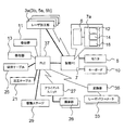
- FIG. 1 is a block diagram of a marking device 1 according to an embodiment of the present invention, in which a thick line indicates a connection by a dedicated line, a waveform line indicates a connection by communication, a thin line indicates a connection by an I / O (input / output) port, and a dotted line Means an analog line connection.
- a thick line indicates a connection by a dedicated line
- a waveform line indicates a connection by communication
- a thin line indicates a connection by an I / O (input / output) port
- a dotted line Means an analog line connection.
- FIG. 4 is a plan view showing an example of a drawing pattern 113 formed on a film 100.
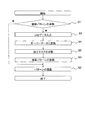
- FIG. It is a flowchart which shows the procedure of marking using the marking apparatus.
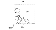
- FIG. 7 is a plan view showing an example of a drawing pattern 113 formed on a film 100, and is an enlarged view of the vicinity of the wiring pattern 70 of FIG. It is an enlarged view of the area
- FIG. 9 is a plan view showing an example of a first drawing pattern 115, corresponding to FIG.
- FIG. 9 is a plan view illustrating an example of a second drawing pattern 117, corresponding to FIG. It is a detailed flowchart of S6 of FIG.
- the marking device 1 a laser marking device that performs marking on the surface of the film 100 using a laser is illustrated.
- the marking device 1 according to the present invention includes a plurality of marking portions. In this example, first and second marking portions are provided.
- the illustrated marking device 1 includes two first laser processing units 3a and 3b as a first marking unit for marking a workpiece with a laser having a first dot diameter, and a first dot diameter.
- Two second laser processing parts 5a and 5b are provided as second marking parts for marking a workpiece with a laser having a second dot diameter smaller than that of the laser beam.
- the device PC7 shown in FIG. 2 operates together with a PLC (Programmable Logic Controller) 37 as a control device for controlling marking described later.
- PLC Programmable Logic Controller
- the apparatus PC7 has a control unit 6 and a storage unit 7a, and the storage unit 7a stores a drawing area which is information on the entire pattern shape to be marked, and the first laser processing units 3a and 3b.
- the apparatus PC 7 operates as a divided drawing pattern registration unit that divides and registers a drawing pattern.
- the apparatus PC7 performs the process of registering the drawing pattern and generating the first drawing pattern and the second drawing pattern by dividing the drawing pattern, so that the apparatus PC7 performs the entire drawing pattern registration unit and the division. It has a function as a drawing pattern generation unit.
- the configuration of the marking device 1 will be described in more detail with reference to FIGS.
- the marking device 1 has an unwinder 11 for unwinding a film 100 as a workpiece, and a winder 13 for unwinding the film 100 unwound from the unwinder 11. is doing.
- the film 100 is obtained by forming a metal layer 103 on a base material 101 such as a polymer film, and the first laser processing portions 3 a and 3 b and the second laser processing are formed on the metal layer 103.
- the irradiated portions are removed and a predetermined wiring pattern is formed.
- a processing table as a relative moving unit that holds the marking area 203 (details will be described later) of the film 100 between the unwinder 11 and the winder 13 and below the film 100. 21 is provided.
- the processing table 21 is driven by the drive unit 23 in directions parallel to the transport direction of the film 100, + x and ⁇ x in FIG. 1, and + z and ⁇ z that are parallel to the normal direction of the surface of the film 100. It is possible to move in the direction.
- the processing table 21 has a movable distance in the + x and ⁇ x directions limited to the distance H in FIG. 1, and holding tables 25 for temporarily adsorbing and holding the film 100 at both ends of the movement limit. Is provided.
- the holding table 25 can be moved in the directions of + z and ⁇ z in FIG. 1 by an actuator (not shown).
- the processing table 21 adsorbs the film 100 at the time of marking, and prevents the position of the film 100 from being displaced by moving following the film 100 at the time of film conveyance.
- the processing table 21 When the processing table 21 reaches the movement limit due to the conveyance of the film 100, the film 100 is temporarily sucked by the holding table 25, and the processing table 21 is separated from the film 100 to the upstream side (unwinder 11 side). Return the processing table to.
- the first laser processing units 3a, 3b and the second laser processing units 5a, 5b are provided above the processing table 21, and further, alignment as an overlay deviation amount measuring unit for alignment correction described later.
- a unit 27 is provided. As shown in FIG. 2, the alignment unit 27 is provided with an imaging unit 28 such as a CCD (Charge Coupled Device) camera as a reference mark imaging unit.
- CCD Charge Coupled Device
- the first laser processing units 3a and 3b are fixed, but the second laser processing units 5a and 5b are provided with a driving stage 29 such as an XY ⁇ stage or a UVW stage as a marking position correction unit.
- the second laser processing units 5a and 5b can move relative to the film 100 and the first laser processing units 3a and 3b in the horizontal (XY) direction and the rotation ( ⁇ ) direction with the z direction as the rotation axis. It has become.
- the marking device 1 has a laser power meter 33 and a converter 35 for measuring the output of the laser.
- the device PC7 is a computer that drives and controls each component of the marking device 1.
- the device PC7 is provided with a monitor 8 and a keyboard 10 for operating the device PC7 as input / output devices. These input / output devices may be tablet-type input / output devices.
- the apparatus PC7 controls the processing table 21 (and the unwinder 11 and the winder 13) to move the first laser processing units 3a and 3b and the second laser processing units 5a and 5b relative to the film 100. It also has a function as a movement marking control unit that performs marking while moving. Furthermore, as described above, in this embodiment, the apparatus PC 7 and the PLC 37 operate as a control apparatus that controls marking described later. More specifically, the apparatus PC7 uses the laser processing conditions (laser current value, laser oscillation frequency, galvano scanning speed, conveyance speed of the processing table 21) of the first laser processing units 3a, 3b and the second laser processing units 5a, 5b.
- laser processing conditions laser current value, laser oscillation frequency, galvano scanning speed, conveyance speed of the processing table 21
- the conveyance distance of the processing table 21, the conditions of the alignment unit 27, the conditions of the laser power meter 33, the layout of the laser processing, the accuracy correction data of the laser processing, and the first laser processing units 3a, 3b and the second laser processing unit In addition to mainly performing processing instruction control related to 5a and 5b, it also plays a role of transmitting information (processing completion trigger) indicating that processing is completed to the PLC 37.
- the PLC 37 controls the operation of the processing table 21, the operation of the holding table 25, the control of the holding table 25 of the processing table 21 and the vacuum suction and release of the suction, the operation of a dust collector (not shown), a laser chiller, a table nip, etc
- first laser processing units 3a, 3b, second laser processing units 5a, 5b, unwinder 11, winder 13, processing table 21, holding table 25, alignment unit 27, drive stage 29, laser power meter 33 (converter 35) is connected via a PLC (Programmable Logic Controller) 37.
- PLC Programmable Logic Controller
- the illustrated first laser processing units 3a and 3b, second laser processing units 5a and 5b are in the direction in which the first laser processing units 3a and 3b and the second laser processing units 5a and 5b are in the transport direction of the film 100. It is arranged in parallel (perpendicular to the conveying direction).
- the regions (marking area 203) for marking at one time on the film 100 are rough processing regions 103a and 103b processed by the first laser processing units 3a and 3b and the second laser processing unit 5a as shown in FIG. 5b is divided into four finely processed regions 105a and 105b to be processed.
- the marking area 203 is drawn by the first drawing pattern (2 regions) drawn by the first laser processing units 3a and 3b and the second drawing pattern (2 regions) drawn by the second laser processing units 5a and 5b (The information of the pattern divided into (2 areas) needs to be registered in the apparatus PC 7 in advance.
- the first laser processing unit 3a is provided on a light source 51 that emits a laser such as a YAG (Yttrium Aluminum Garnet) laser, and on the optical path of the laser emitted from the light source, and adjusts the dot diameter of the laser Adjustment of the focal point in the Z-axis (see FIG. 5) direction of the laser incident from the corner mirrors 55 and 57 and the corner mirrors 57 for changing the direction of the laser beam transmitted through the beam expander 53.
- the laser irradiated with a predetermined output from the light source 51 is adjusted to a predetermined dot diameter by the beam expander 53, and irradiated by the Z scanner 59, the objective lens 61, and the XY galvano scanner 63.
- the position coordinates and the focal point at that position are adjusted, and a desired position on the film 100 is irradiated with the first dot diameter 303.
- the dot diameter can be varied by adjusting the Z scanner 59, the objective lens 61, and the like.
- the present invention adjusts the plurality of laser processing portions so that lasers with different dot diameters have substantially the same energy on the film 100.
- the output of the first laser processing units 3a and 3b is 11 watts, and the repetition frequency is 40 kHz.
- the second laser processing units 5a and 5b differ from the first laser processing units 3a and 3b only in that the laser is irradiated with the second dot diameter 304.
- the size of the second dot diameter 304 is not particularly limited as long as it is smaller than the first dot diameter.
- the diameter of the first dot diameter 303 and the diameter of the second dot diameter 304 are not limited.
- the ratio is about 4: 1.
- the output of the second laser processing units 5a and 5b is 2 watts, and the repetition frequency is 40 kHz.
- the drawing pattern 113 in the rectangular marking area 203 is provided with 16 wiring patterns 70, and further, alignment confirmation reference marks 71 for alignment are provided at the four corners of the marking area 203. ing.
- the apparatus PC7 (the control unit 6) of the marking apparatus 1 determines whether or not the drawing pattern 113 and the first drawing pattern and the second drawing pattern corresponding to the drawing pattern are registered in the storage unit 7a (see FIG. 7 (S1), if registered, marking (pattern drawing) is performed according to the registered pattern (S2 in FIG. 7).
- the control unit 6 of the apparatus PC 7 When the first drawing pattern and the second drawing pattern are not registered, the control unit 6 of the apparatus PC 7 generates and registers the first drawing pattern and the second drawing pattern (divided drawing pattern) according to the following procedure.
- the apparatus PC7 is used as a divided drawing pattern generation unit (or divided drawing pattern generation apparatus) for generating a divided drawing pattern.
- the drawing pattern is produced not by the apparatus PC7 but by another computer (pattern generation apparatus). ) May be used.
- control unit 6 of the apparatus PC 7 reads pattern shape data such as CAD data corresponding to the drawing pattern (S3 in FIG. 7).
- control unit 6 of the apparatus PC 7 converts the read CAD data into Gerber data (S4 in FIG. 7).
- the control unit 6 of the apparatus PC 7 divides the Gerber data into a plurality of regions corresponding to the number of laser processing units (S5 in FIG. 7).
- the way of division and the shape of the region are the same as in FIG. That is, since the marking device 1 has four laser processing parts, the first laser processing parts 3a and 3b and the second laser processing parts 5a and 5b, the Gerber data is divided into four regions.
- control unit 6 of the apparatus PC 7 generates and registers the first drawing pattern and the second drawing pattern from the divided areas and registers them (S6 in FIG. 7).
- the first laser processing units 3a and 3b for drawing the first drawing pattern have a larger laser dot diameter at the time of drawing than the second laser processing units 5a and 5b for drawing the second drawing pattern. Since a large area can be drawn at high speed, an area that can be drawn with the first dot diameter 303 is basically set as a first drawing pattern.
- a second drawing pattern is set as a region that complements a region that is not drawn with the first dot diameter 303.
- Such areas include areas as shown in FIGS. 8 and 9.
- the regions 305, 306, 307, and 309 smaller than D are subjected to the first laser processing. Since the portions 3a and 3b cannot be drawn, the second drawing pattern drawn by the second laser processing portions 5a and 5b having the second dot diameter 304 is set.
- FIG. 10 shows the first drawing pattern 115 generated in this way
- FIG. 11 shows the second drawing pattern 117.
- the above is the method of dividing the drawing pattern into the first drawing pattern and the second drawing pattern.
- the marking apparatus 1 can simultaneously improve the processing accuracy and shorten the working time by accurately drawing the portion that requires the processing by the laser processing unit having a small dot diameter.
- the marking device 1 (PLC 37 of the device PC7) drives the unwinder 11 and the winder 13 with a motor or the like (not shown), and the marking area of the film 100 at a position where the first laser processing units 3a and 3b can draw.
- the film 100 is conveyed so that 203 is arranged (S11 in FIG. 12).
- the processing table 21 moves under the control of the PLC 37 while adsorbing and holding the lower surface of the marking area 203.
- the PLC 37 transmits information (movement completion trigger) indicating that the movement is completed and position information of the machining table 21 to the apparatus PC7.
- the apparatus PC 7 that has received the movement completion trigger and the position information of the processing table 21 matches the position information from the processing layout of the storage unit 7 a based on the position information of the processing table 21 (first drawing pattern). ) Is selected, and processing is instructed to the first laser processing units 3a and 3b (laser processing unit PC39) based on the selected processing layout.
- the first laser processing units 3a and 3b perform patterning by irradiating the rough processing regions 103a and 103b with laser based on the first drawing pattern (S12 in FIG. 12).
- the reference mark 71 for position confirmation is drawn in the rough processing regions 103a and 103b by the first laser processing units 3a and 3b.
- the position confirmation reference mark 71 depicted by the first laser processing parts 3a and 3b is referred to as a first position confirmation reference mark 73.
- the apparatus PC 7 transmits information (machining completion trigger) indicating that the machining is completed to the PLC 37.
- the PLC 37 that has received the processing completion trigger drives the unwinder 11 and the winder 13 with a motor or the like (not shown), and the regions corresponding to the previous rough processing regions 103a and 103b are the next micro-processing regions 105a and 105b.
- the film 100 is conveyed in the direction of + x to a position overlapping with (S13 in FIG. 12).
- the processing table 21 also moves following the conveyance while adsorbing and holding the lower surface of the marking area 203.
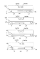
- the PLC 7 uses the alignment unit 27 to image the first position confirmation reference mark 73 moved to the microfabrication regions 105a and 105b by the imaging unit 28, and causes the alignment unit 27 to calculate the position shift. It is determined whether or not the positional deviation is within an allowable range. If the positional deviation is not within the allowable range, alignment correction is performed (S14 in FIG. 12, FIG. 13A). The alignment correction is performed, for example, by the PLC 7 controlling the drive stage 29 to correct the positions of the second laser processing units 5a and 5b. When the alignment correction is finished or the calculation of the position deviation is finished (when the position deviation is within an allowable range), the PLC 7 obtains information (alignment completion trigger) indicating that the alignment is completed and the position information of the processing table 21. It transmits to apparatus PC7.
- information alignment completion trigger
- the apparatus PC7 that has received the alignment completion trigger and the position information of the processing table 21 is based on the position information of the processing table 21 and the first drawing pattern and the first drawing pattern that match the position information from the processing layout of the storage unit 7a.
- Two drawing patterns are selected, and processing is instructed to the first laser processing units 3a and 3b and the second laser processing units 5a and 5b (laser processing unit PC39) based on the selected drawing pattern.
- the first laser processing units 3a and 3b and the second laser processing units 5a and 5b that have received the instructions are divided into rough processing regions 103a and 103b and fine processing regions 105a and 105b based on the first drawing pattern and the second drawing pattern. Patterning is performed by laser irradiation (S15 in FIG. 12, FIG. 13B).
- the second drawing pattern is formed in the microfabrication regions 105a and 105b so as to overlap the region where the first drawing pattern is formed in S12, and the entire drawing pattern is drawn.
- the first laser processing units 3a and 3b depict the first position confirmation reference marks 73 in the rough processing regions 103a and 103b, similarly to S12.
- the second laser processing parts 5a and 5b also draw the position confirmation reference marks 71 in the micro-processed areas 105a and 105b.
- the reference mark 71 for position confirmation depicted by the second laser processing parts 5a and 5b is referred to as a second reference mark 75 for position confirmation.
- the first position confirmation reference mark 73 and the second position confirmation reference mark 75 are drawn so as to overlap with the place where the position confirmation reference mark 71 is to be drawn. .
- the apparatus PC 7 transmits a machining completion trigger to the PLC 37.
- the PLC 37 that has received the processing completion trigger uses the alignment unit 27 to image the portion where the first position confirmation reference mark 73 and the second position confirmation reference mark 75 are overlapped by the imaging unit 28, as shown in FIG.
- the alignment unit 27 measures the relative displacement G between the first position confirmation reference mark 73 and the second position confirmation reference mark 75. If the positional deviation G is not within the allowable range, alignment correction is performed (S16 in FIG. 12, FIG. 13C).
- As a specific alignment correction method there is a method of correcting the laser irradiation condition using the laser processing unit PC39 in addition to the method described in S14.
- the PLC 37 of the marking device 1 determines whether or not the position of the processing table 21 is at the movement limit on the downstream side (winder 13 side) (S17 in FIG. 12). If not, the process returns to S13.
- the marking device 1 When the position of the machining table 21 is at the downstream movement limit, the marking device 1 needs to return the machining table 21 to the upstream side (unwinder 11 side), and therefore moves the machining table 21 according to the following procedure.
- the PLC 37 of the marking device 1 moves the holding table 25 in the + z direction by using an actuator (not shown) or the like, and sucks and holds the film 100 (S18 in FIG. 12, FIG. 13 (d)).
- the PLC 37 of the marking device 1 releases the adsorption of the film 100 by the processing table 21, and moves the processing table 21 in the -z direction using the driving unit 23 to separate it from the film 100 (S19 in FIG. 12, FIG. 14 (a)).
- the PLC 37 of the marking device 1 uses the drive unit 23 to move the processing table 21 in the -x direction and moves it upstream (S20 in FIG. 12, FIG. 14 (b)).
- the PLC 37 of the marking device 1 uses the drive unit 23 to move the processing table 21 in the + z direction to contact the film 100 again, thereby attracting the film 100 (S21 in FIG. 12, FIG. 14 (c)). .
- the PLC 37 of the marking device 1 releases the suction of the holding table 25 to the film 100, moves the holding table 25 in the direction of ⁇ z, and pulls it away from the film 100 (S22 in FIG. 12, FIG. 14 (d)). .
- the processing table 21 since the processing table 21 always holds the marking area 203 by suction from below, the positional deviation of the film 100 at the time of marking can be minimized.
- the marking device 1 includes the first laser processing units 3a and 3b as the first marking units for marking the workpiece with the first dot diameter 303, and the first laser processing units 3a and 3b.
- the second laser processing units 5a and 5b serving as second marking units for marking the workpiece with the second dot diameter 304 smaller than the dot diameter and the drawing pattern are drawn by the first laser processing units 3a and 3b.
- It has apparatus PC7 as a division
- the marking device 1 can simultaneously improve processing accuracy and shorten work time.
- the marking device 1 is exemplified by a device that performs marking using a laser.
- the present invention is not limited to this, and any device that can mark a workpiece is used.
- an apparatus for marking using a coating apparatus such as an inkjet or a dispenser may be used.
- the alignment correction is performed every time the film 100 is moved.
- the conditions for performing the alignment correction are not limited to this, and each time the film is moved several times, the alignment correction is performed. You may perform alignment correction on various conditions, such as after progress, or after a new drawing pattern is registered.
- marking is performed by arranging the first laser processing units 3a and 3b and the second laser processing units 5a and 5b in parallel two by two, but each one or three or more You may arrange a laser processing part.
- the film 100 is moved and the second laser processing units 5a and 5b perform the second drawing.
- the drawing pattern is drawn, the first drawing pattern and the second drawing pattern may be drawn simultaneously. That is, the drawing may be performed without dividing the processing region into the rough processing region and the fine processing region.
- the marking object (workpiece) to which the present invention can be applied is not limited to a long sheet such as the film 100, but a rectangular substrate such as a glass plate or a printed board, or a circular substrate such as a semiconductor wafer or a glass wafer. Etc. can be illustrated.
Landscapes
- Engineering & Computer Science (AREA)
- Physics & Mathematics (AREA)
- Optics & Photonics (AREA)
- Plasma & Fusion (AREA)
- Mechanical Engineering (AREA)
- Laser Beam Processing (AREA)
- Manufacturing Of Printed Circuit Boards (AREA)
Abstract
Description
3a :第1レーザ加工部
3b :第1レーザ加工部
5a :第2レーザ加工部
6 :制御部
7 :装置PC
7a :記憶部
8 :モニタ
10 :キーボード
11 :巻出器
12 :格納領域
13 :巻取器
14 :第1の部分格納領域
16 :第2の部分格納領域
21 :加工テーブル
23 :駆動部
25 :保持テーブル
27 :アライメントユニット
28 :撮像部
29 :駆動ステージ
33 :レーザパワーメータ
35 :変換器
39 :レーザ加工ユニットPC
51 :光源
53 :ビームエキスパンダ
55 :コーナーミラー
57 :コーナーミラー
59 :Zスキャナ
61 :対物レンズ
63 :XYガルバノスキャナ
70 :配線パターン
71 :位置確認用基準マーク
73 :第1位置確認用基準マーク
75 :第2位置確認用基準マーク
100 :フィルム
101 :基材
103 :金属層
103a :粗加工領域
105a :微細加工領域
113 :描画パターン
115 :第1描画パターン
117 :第2描画パターン
203 :マーキングエリア
303 :第1のドット径
304 :第2のドット径
305 :領域
311 :角部
313 :輪郭
315 :隙間
G :位置ずれ
H :距離
Claims (9)
- 被加工物に設定したマーキングエリアに所定の描画パターンを描画するマーキング装置において、
第1のドット径で前記被加工物にマーキングを行う第1マーキング部と、
前記第1のドット径よりもドット径の小さい第2のドット径で前記被加工物にマーキングを行う第2マーキング部と、
前記描画パターンを、前記第1マーキング部で描画する第1描画パターンおよび前記第2マーキング部で描画する第2描画パターンに分割して登録する、分割描画パターン登録部と、
を有することを特徴とするマーキング装置。 - 前記第2描画パターンは、所定の前記描画パターンのうち、前記第1描画パターンで描画されない部分を補完するパターンで構成されていることを特徴とする、請求項1に記載のマーキング装置。
- 前記第2描画パターンは、所定の前記描画パターンのうち、前記第1のドット径で描画できない部分を描画するパターンで構成されていることを特徴とする、請求項2に記載のマーキング装置。
- 前記第2描画パターンは、所定の前記描画パターンのうち第1描画パターンと、所定の前記描画パターンの輪郭部の間を補完するパターンで構成されていることを特徴とする、
請求項1~3のいずれか一項に記載のマーキング装置。 - 前記第1マーキング部でマーキングされ、マーキングエリアの基準位置を示す第1位置確認用基準マークを撮像する基準マーク撮像部と、
前記基準マーク撮像部で撮像した前記第1位置確認用基準マークの位置情報に基づいて、前記第2マーキング部でマーキングする位置を補正する、マーキング位置補正部を備え、
前記第2マーキング部は、前記マーキング位置補正部で補正された位置でマーキングを行うことを特徴とする、請求項1~4のいずれか一項に記載のマーキング装置。 - 前記第1マーキング部でマーキングした前記第1位置確認用基準マークと、前記第2マーキング部でマーキングされ、マーキングエリアの基準位置を示す第2位置確認用基準マークとを前記基準マーク撮像部で撮像し、当該第1位置確認用基準マークと当該第2位置確認用基準マークとの相対的な位置ずれ量を測定する、重ね合わせずれ量測定部を備えた、ことを特徴とする、請求項5に記載のマーキング装置。
- 前記被加工物と前記第1マーキング部および前記第2マーキング部を相対的に移動させる相対移動部と、
前記相対移動部を制御して前記被加工物に対して前記第1マーキング部および前記第2マーキング部を相対的に移動させながらマーキングを行う移動マーキング制御部を備えた、
請求項1~6のいずれか一項に記載のマーキング装置。 - 前記被加工物にマーキングする全体の前記描画パターンを全体描画パターンとして登録する全体描画パターン登録部と、
前記全体描画パターンから前記第1描画パターンおよび前記第2描画パターンを分割生成する分割描画パターン生成部を備えた、
請求項1~7のいずれか一項に記載のマーキング装置。 - 請求項1~7のいずれか一項に記載のマーキング装置でマーキングする全体の前記描画パターンを全体描画パターンとして登録する全体描画パターン登録部と、
前記全体描画パターンから前記第1描画パターンおよび前記第2描画パターンを分割生成する分割描画パターン生成部を備えた、
パターン生成装置。
Priority Applications (2)
| Application Number | Priority Date | Filing Date | Title |
|---|---|---|---|
| KR1020167023118A KR102192600B1 (ko) | 2014-02-27 | 2015-01-15 | 마킹 장치 및 패턴 생성 장치 |
| CN201580009197.8A CN106029288A (zh) | 2014-02-27 | 2015-01-15 | 标印装置和图案生成装置 |
Applications Claiming Priority (2)
| Application Number | Priority Date | Filing Date | Title |
|---|---|---|---|
| JP2014-037194 | 2014-02-27 | ||
| JP2014037194A JP6278451B2 (ja) | 2014-02-27 | 2014-02-27 | マーキング装置およびパターン生成装置 |
Publications (1)
| Publication Number | Publication Date |
|---|---|
| WO2015129316A1 true WO2015129316A1 (ja) | 2015-09-03 |
Family
ID=54008645
Family Applications (1)
| Application Number | Title | Priority Date | Filing Date |
|---|---|---|---|
| PCT/JP2015/050866 Ceased WO2015129316A1 (ja) | 2014-02-27 | 2015-01-15 | マーキング装置およびパターン生成装置 |
Country Status (5)
| Country | Link |
|---|---|
| JP (1) | JP6278451B2 (ja) |
| KR (1) | KR102192600B1 (ja) |
| CN (1) | CN106029288A (ja) |
| TW (1) | TWI627006B (ja) |
| WO (1) | WO2015129316A1 (ja) |
Cited By (8)
| Publication number | Priority date | Publication date | Assignee | Title |
|---|---|---|---|---|
| JP2017052103A (ja) * | 2015-09-07 | 2017-03-16 | 凸版印刷株式会社 | フィルムへのレーザー加工方法 |
| WO2017061222A1 (ja) * | 2015-10-09 | 2017-04-13 | 東レエンジニアリング株式会社 | マーキング装置 |
| CN109014595A (zh) * | 2018-09-12 | 2018-12-18 | 昆山卓研智能科技有限公司 | 离线全自动标识设备 |
| US10213974B2 (en) | 2015-09-07 | 2019-02-26 | Toppan Printing Co., Ltd. | Laser processing apparatus |
| JP2020019058A (ja) * | 2018-08-03 | 2020-02-06 | ファナック株式会社 | レーザ加工装置の制御装置及びレーザ加工装置 |
| CN114260588A (zh) * | 2022-01-10 | 2022-04-01 | 中国科学院力学研究所 | 一种振镜式大幅面激光飞行打标方法 |
| CN116851929A (zh) * | 2023-09-04 | 2023-10-10 | 武汉华工激光工程有限责任公司 | 一种运动状态下的物体视觉定位激光打标方法及系统 |
| CN117260002A (zh) * | 2023-11-20 | 2023-12-22 | 西安精谐科技有限责任公司 | 基于激光加工的半球谐振陀螺电极及加工方法、系统 |
Families Citing this family (5)
| Publication number | Priority date | Publication date | Assignee | Title |
|---|---|---|---|---|
| EP3421225A1 (de) | 2017-06-26 | 2019-01-02 | Raylase GmbH | Automatisierte kalibrierung einer vorrichtung zur vollparallelisierten additiven fertigung eines bauteils mit kombinierten arbeitsfeldern |
| WO2019082314A1 (ja) | 2017-10-25 | 2019-05-02 | 株式会社ニコン | 加工装置、加工システム、及び、移動体の製造方法 |
| JP7252769B2 (ja) * | 2019-02-01 | 2023-04-05 | 株式会社ディスコ | アライメント方法 |
| JP7596849B2 (ja) | 2021-02-25 | 2024-12-10 | 株式会社リコー | マーキング装置、及びマーキング方法 |
| JP7600754B2 (ja) | 2021-02-26 | 2024-12-17 | 株式会社リコー | レーザ照射装置、レーザ照射方法 |
Citations (2)
| Publication number | Priority date | Publication date | Assignee | Title |
|---|---|---|---|---|
| JP2006224481A (ja) * | 2005-02-18 | 2006-08-31 | Dainippon Screen Mfg Co Ltd | 印刷版の製版装置 |
| JP2013184171A (ja) * | 2012-03-06 | 2013-09-19 | Toray Eng Co Ltd | マーキング装置及び方法 |
Family Cites Families (6)
| Publication number | Priority date | Publication date | Assignee | Title |
|---|---|---|---|---|
| WO1997040957A1 (es) * | 1996-04-26 | 1997-11-06 | Servicio Industrial De Marcaje Y Codificacion, S.A. | Sistema y procedimiento de marcaje o de perforacion |
| JP4461740B2 (ja) | 2003-08-21 | 2010-05-12 | オムロン株式会社 | レーザマーキング装置 |
| JP3872462B2 (ja) | 2003-09-01 | 2007-01-24 | 住友重機械工業株式会社 | レーザ加工装置、及びレーザ加工方法 |
| JP2006095931A (ja) * | 2004-09-30 | 2006-04-13 | Dainippon Screen Mfg Co Ltd | 印刷版の製版方法および印刷版の製版装置 |
| JP5248205B2 (ja) | 2008-05-29 | 2013-07-31 | パナソニック デバイスSunx株式会社 | レーザマーキング装置 |
| JP4734437B2 (ja) * | 2009-04-17 | 2011-07-27 | 沓名 宗春 | 繊維強化複合材料のレーザ加工方法 |
-
2014
- 2014-02-27 JP JP2014037194A patent/JP6278451B2/ja not_active Expired - Fee Related
-
2015
- 2015-01-15 KR KR1020167023118A patent/KR102192600B1/ko not_active Expired - Fee Related
- 2015-01-15 CN CN201580009197.8A patent/CN106029288A/zh active Pending
- 2015-01-15 WO PCT/JP2015/050866 patent/WO2015129316A1/ja not_active Ceased
- 2015-01-29 TW TW104103071A patent/TWI627006B/zh not_active IP Right Cessation
Patent Citations (2)
| Publication number | Priority date | Publication date | Assignee | Title |
|---|---|---|---|---|
| JP2006224481A (ja) * | 2005-02-18 | 2006-08-31 | Dainippon Screen Mfg Co Ltd | 印刷版の製版装置 |
| JP2013184171A (ja) * | 2012-03-06 | 2013-09-19 | Toray Eng Co Ltd | マーキング装置及び方法 |
Cited By (13)
| Publication number | Priority date | Publication date | Assignee | Title |
|---|---|---|---|---|
| US10213974B2 (en) | 2015-09-07 | 2019-02-26 | Toppan Printing Co., Ltd. | Laser processing apparatus |
| JP2017052103A (ja) * | 2015-09-07 | 2017-03-16 | 凸版印刷株式会社 | フィルムへのレーザー加工方法 |
| TWI677392B (zh) * | 2015-10-09 | 2019-11-21 | 日商東麗工程股份有限公司 | 標記裝置 |
| CN108025392A (zh) * | 2015-10-09 | 2018-05-11 | 东丽工程株式会社 | 标印装置 |
| JP2017070989A (ja) * | 2015-10-09 | 2017-04-13 | 東レエンジニアリング株式会社 | マーキング装置 |
| WO2017061222A1 (ja) * | 2015-10-09 | 2017-04-13 | 東レエンジニアリング株式会社 | マーキング装置 |
| JP2020019058A (ja) * | 2018-08-03 | 2020-02-06 | ファナック株式会社 | レーザ加工装置の制御装置及びレーザ加工装置 |
| US11945044B2 (en) | 2018-08-03 | 2024-04-02 | Fanuc Corporation | Control device for laser machining apparatus, and laser machining apparatus |
| CN109014595A (zh) * | 2018-09-12 | 2018-12-18 | 昆山卓研智能科技有限公司 | 离线全自动标识设备 |
| CN114260588A (zh) * | 2022-01-10 | 2022-04-01 | 中国科学院力学研究所 | 一种振镜式大幅面激光飞行打标方法 |
| CN116851929A (zh) * | 2023-09-04 | 2023-10-10 | 武汉华工激光工程有限责任公司 | 一种运动状态下的物体视觉定位激光打标方法及系统 |
| CN117260002A (zh) * | 2023-11-20 | 2023-12-22 | 西安精谐科技有限责任公司 | 基于激光加工的半球谐振陀螺电极及加工方法、系统 |
| CN117260002B (zh) * | 2023-11-20 | 2024-02-09 | 西安精谐科技有限责任公司 | 基于激光加工的半球谐振陀螺电极及加工方法、系统 |
Also Published As
| Publication number | Publication date |
|---|---|
| CN106029288A (zh) | 2016-10-12 |
| KR20160125971A (ko) | 2016-11-01 |
| KR102192600B1 (ko) | 2020-12-17 |
| JP6278451B2 (ja) | 2018-02-14 |
| JP2015160235A (ja) | 2015-09-07 |
| TWI627006B (zh) | 2018-06-21 |
| TW201532720A (zh) | 2015-09-01 |
Similar Documents
| Publication | Publication Date | Title |
|---|---|---|
| JP6278451B2 (ja) | マーキング装置およびパターン生成装置 | |
| US20180264599A1 (en) | Laser processing apparatus | |
| JP5896459B2 (ja) | マーキング装置及び方法 | |
| JP6223091B2 (ja) | 位置計測装置、アライメント装置、パターン描画装置および位置計測方法 | |
| CN111992893A (zh) | 激光加工装置 | |
| JP2018008307A (ja) | 光加工装置及び光加工物の生産方法 | |
| KR20130098838A (ko) | 레이저 가공 장치, 레이저 가공 방법 및 레이저 가공 프로그램을 기록한 컴퓨터가 판독 가능한 기록 매체 | |
| CN108025392B (zh) | 标印装置 | |
| WO2016117224A1 (ja) | マーキング装置および方法、パターン生成装置、並びに被加工物 | |
| WO2016147977A1 (ja) | 描画装置 | |
| JP6313148B2 (ja) | マーキング装置 | |
| JP2012209443A (ja) | パターン描画装置およびパターン描画方法 | |
| JP2017113787A (ja) | 光加工装置 | |
| JP2009006339A (ja) | レーザ加工装置、及び、レーザ加工方法 | |
| JP2005088045A (ja) | レーザ穴あけ方法及び装置 | |
| JP4886719B2 (ja) | 加工装置 | |
| JP2008046457A (ja) | 描画装置 | |
| JP2002001562A (ja) | 光加工方法及びその装置並びに記録媒体 | |
| TW201032936A (en) | System and method for laser processing | |
| JP7451049B2 (ja) | レーザ加工装置及びレーザ加工方法 | |
| JP2011031248A (ja) | レーザ加工装置及びレーザ加工方法 | |
| CN116060799A (zh) | 照明光学系统和激光加工装置 | |
| CN116060798A (zh) | 照明光学系统和激光加工装置 | |
| JP2016161825A (ja) | 露光装置、基板、および露光方法 | |
| JP2014146011A (ja) | パターン形成装置及びパターン形成方法 |
Legal Events
| Date | Code | Title | Description |
|---|---|---|---|
| 121 | Ep: the epo has been informed by wipo that ep was designated in this application |
Ref document number: 15754860 Country of ref document: EP Kind code of ref document: A1 |
|
| ENP | Entry into the national phase |
Ref document number: 20167023118 Country of ref document: KR Kind code of ref document: A |
|
| NENP | Non-entry into the national phase |
Ref country code: DE |
|
| 32PN | Ep: public notification in the ep bulletin as address of the adressee cannot be established |
Free format text: NOTING OF LOSS OF RIGHTS PURSUANT TO RULE 112(1) EPC (EPO FORM 1205A DATED 09.12.2016) |
|
| 122 | Ep: pct application non-entry in european phase |
Ref document number: 15754860 Country of ref document: EP Kind code of ref document: A1 |