WO2015111302A1 - 空気入りタイヤ - Google Patents
空気入りタイヤ Download PDFInfo
- Publication number
- WO2015111302A1 WO2015111302A1 PCT/JP2014/081783 JP2014081783W WO2015111302A1 WO 2015111302 A1 WO2015111302 A1 WO 2015111302A1 JP 2014081783 W JP2014081783 W JP 2014081783W WO 2015111302 A1 WO2015111302 A1 WO 2015111302A1
- Authority
- WO
- WIPO (PCT)
- Prior art keywords
- groove
- shoulder
- tire
- center
- grooves
- Prior art date
Links
Images


Classifications
-
- B—PERFORMING OPERATIONS; TRANSPORTING
- B60—VEHICLES IN GENERAL
- B60C—VEHICLE TYRES; TYRE INFLATION; TYRE CHANGING; CONNECTING VALVES TO INFLATABLE ELASTIC BODIES IN GENERAL; DEVICES OR ARRANGEMENTS RELATED TO TYRES
- B60C11/00—Tyre tread bands; Tread patterns; Anti-skid inserts
- B60C11/03—Tread patterns
- B60C11/0302—Tread patterns directional pattern, i.e. with main rolling direction
-
- B—PERFORMING OPERATIONS; TRANSPORTING
- B60—VEHICLES IN GENERAL
- B60C—VEHICLE TYRES; TYRE INFLATION; TYRE CHANGING; CONNECTING VALVES TO INFLATABLE ELASTIC BODIES IN GENERAL; DEVICES OR ARRANGEMENTS RELATED TO TYRES
- B60C11/00—Tyre tread bands; Tread patterns; Anti-skid inserts
- B60C11/03—Tread patterns
- B60C11/0306—Patterns comprising block rows or discontinuous ribs
-
- B—PERFORMING OPERATIONS; TRANSPORTING
- B60—VEHICLES IN GENERAL
- B60C—VEHICLE TYRES; TYRE INFLATION; TYRE CHANGING; CONNECTING VALVES TO INFLATABLE ELASTIC BODIES IN GENERAL; DEVICES OR ARRANGEMENTS RELATED TO TYRES
- B60C11/00—Tyre tread bands; Tread patterns; Anti-skid inserts
- B60C11/03—Tread patterns
- B60C11/12—Tread patterns characterised by the use of narrow slits or incisions, e.g. sipes
-
- B—PERFORMING OPERATIONS; TRANSPORTING
- B60—VEHICLES IN GENERAL
- B60C—VEHICLE TYRES; TYRE INFLATION; TYRE CHANGING; CONNECTING VALVES TO INFLATABLE ELASTIC BODIES IN GENERAL; DEVICES OR ARRANGEMENTS RELATED TO TYRES
- B60C11/00—Tyre tread bands; Tread patterns; Anti-skid inserts
- B60C11/03—Tread patterns
- B60C11/13—Tread patterns characterised by the groove cross-section, e.g. for buttressing or preventing stone-trapping
- B60C11/1376—Three dimensional block surfaces departing from the enveloping tread contour
- B60C11/1392—Three dimensional block surfaces departing from the enveloping tread contour with chamfered block edges
-
- B—PERFORMING OPERATIONS; TRANSPORTING
- B60—VEHICLES IN GENERAL
- B60C—VEHICLE TYRES; TYRE INFLATION; TYRE CHANGING; CONNECTING VALVES TO INFLATABLE ELASTIC BODIES IN GENERAL; DEVICES OR ARRANGEMENTS RELATED TO TYRES
- B60C11/00—Tyre tread bands; Tread patterns; Anti-skid inserts
- B60C11/03—Tread patterns
- B60C11/12—Tread patterns characterised by the use of narrow slits or incisions, e.g. sipes
- B60C11/1236—Tread patterns characterised by the use of narrow slits or incisions, e.g. sipes with special arrangements in the tread pattern
- B60C11/125—Tread patterns characterised by the use of narrow slits or incisions, e.g. sipes with special arrangements in the tread pattern arranged at the groove bottom
-
- B—PERFORMING OPERATIONS; TRANSPORTING
- B60—VEHICLES IN GENERAL
- B60C—VEHICLE TYRES; TYRE INFLATION; TYRE CHANGING; CONNECTING VALVES TO INFLATABLE ELASTIC BODIES IN GENERAL; DEVICES OR ARRANGEMENTS RELATED TO TYRES
- B60C11/00—Tyre tread bands; Tread patterns; Anti-skid inserts
- B60C11/03—Tread patterns
- B60C2011/0337—Tread patterns characterised by particular design features of the pattern
- B60C2011/0339—Grooves
- B60C2011/0358—Lateral grooves, i.e. having an angle of 45 to 90 degees to the equatorial plane
- B60C2011/0367—Lateral grooves, i.e. having an angle of 45 to 90 degees to the equatorial plane characterised by depth
- B60C2011/0369—Lateral grooves, i.e. having an angle of 45 to 90 degees to the equatorial plane characterised by depth with varying depth of the groove
-
- B—PERFORMING OPERATIONS; TRANSPORTING
- B60—VEHICLES IN GENERAL
- B60C—VEHICLE TYRES; TYRE INFLATION; TYRE CHANGING; CONNECTING VALVES TO INFLATABLE ELASTIC BODIES IN GENERAL; DEVICES OR ARRANGEMENTS RELATED TO TYRES
- B60C11/00—Tyre tread bands; Tread patterns; Anti-skid inserts
- B60C11/03—Tread patterns
- B60C2011/0337—Tread patterns characterised by particular design features of the pattern
- B60C2011/0339—Grooves
- B60C2011/0374—Slant grooves, i.e. having an angle of about 5 to 35 degrees to the equatorial plane
- B60C2011/0379—Slant grooves, i.e. having an angle of about 5 to 35 degrees to the equatorial plane characterised by depth
-
- B—PERFORMING OPERATIONS; TRANSPORTING
- B60—VEHICLES IN GENERAL
- B60C—VEHICLE TYRES; TYRE INFLATION; TYRE CHANGING; CONNECTING VALVES TO INFLATABLE ELASTIC BODIES IN GENERAL; DEVICES OR ARRANGEMENTS RELATED TO TYRES
- B60C11/00—Tyre tread bands; Tread patterns; Anti-skid inserts
- B60C11/03—Tread patterns
- B60C2011/0337—Tread patterns characterised by particular design features of the pattern
- B60C2011/0339—Grooves
- B60C2011/0381—Blind or isolated grooves
- B60C2011/0383—Blind or isolated grooves at the centre of the tread
-
- B—PERFORMING OPERATIONS; TRANSPORTING
- B60—VEHICLES IN GENERAL
- B60C—VEHICLE TYRES; TYRE INFLATION; TYRE CHANGING; CONNECTING VALVES TO INFLATABLE ELASTIC BODIES IN GENERAL; DEVICES OR ARRANGEMENTS RELATED TO TYRES
- B60C11/00—Tyre tread bands; Tread patterns; Anti-skid inserts
- B60C11/03—Tread patterns
- B60C2011/0337—Tread patterns characterised by particular design features of the pattern
- B60C2011/0386—Continuous ribs
- B60C2011/0388—Continuous ribs provided at the equatorial plane
Definitions
- the present invention relates to a pneumatic tire having good steering stability.
- Patent Document 1 describes a pneumatic tire in which an inclined groove is provided in a middle land portion.
- the present invention has been devised in view of the above circumstances, and its main object is to provide a pneumatic tire having good steering stability.
- the present invention provides the tread portion with a pair of center main grooves disposed on both sides of the tire equator and a pair of shoulder main grooves disposed on both sides of the tire equator.
- a pneumatic tire provided with a middle land portion divided between a groove and the shoulder main groove, wherein each middle land portion is provided with a plurality of middle slant grooves, and each middle slant groove Extends from the outer end in the tire axial direction communicating with the shoulder main groove to the tire equator side, and the inner end in the tire axial direction terminates without communicating with the center main groove.
- An outer shallow bottom portion having a groove depth smaller than the maximum groove depth of the middle inclined groove is provided on the outer end side.
- an inner shallow bottom portion having a depth smaller than a maximum groove depth of the middle inclined groove is provided on the inner end side of the middle inclined groove.
- a depth of the inner shallow bottom portion is smaller than a depth of the outer shallow bottom portion.
- a sipe extending along the middle inclined groove is provided on a groove bottom surface of the outer shallow bottom portion.
- the tread portion is provided with a shoulder land portion outside each shoulder main groove, and each shoulder land portion is provided with a plurality of shoulder lateral grooves.
- the shoulder lateral groove includes a first shoulder lateral groove and a second shoulder lateral groove having a groove width smaller than the first shoulder lateral groove, and the first shoulder main groove and the second shoulder main groove are arranged in the tire circumferential direction. It is desirable to arrange them alternately.
- the groove width of the second shoulder lateral groove is 70% to 90% of the groove width of the first shoulder lateral groove.
- the shoulder lateral groove extends to a grounding end of the tread portion, and an angle of the shoulder lateral groove with respect to a tire circumferential direction at the grounding end is 80 degrees or more.
- the tread portion is provided with a center land portion between the center main grooves, and the center land portion terminates without extending from the center main groove and reaching the tire equator. It is desirable that the rib is provided with a center lug groove.
- the length of the center lug groove in the tire axial direction is preferably 30% or less of the width of the center land portion.
- each middle inclined groove has an outer end in the tire axial direction that communicates with the shoulder main groove, and an inner end in the tire axial direction that terminates without communicating with the center main groove.
- the middle inclined groove can discharge the water film between the middle land and the road surface to the outside of the tire through the shoulder main groove.
- the middle land since the middle sloping groove does not completely cross the middle land, the middle land has high rigidity and exhibits good steering stability.
- the outer shallow bottom portion having a depth smaller than the maximum groove depth of the middle inclined groove is provided on the outer end side of the middle inclined groove, deformation of the middle land portion is effectively performed during turning. Suppressing and better steering stability is exhibited.
- FIG. 3 is a cross-sectional view taken along line AA in FIG. 2. It is a partial expansion perspective view of the tire land direction inside of a middle land part.
- FIG. 3 is a cross-sectional view taken along the line BB in FIG. It is a partial expansion perspective view of a shoulder land part.
- FIG. 1 shows a development view of a tread portion 2 of a pneumatic tire 1 according to an embodiment of the present invention.
- the pneumatic tire of the present embodiment is implemented as a radial tire 1 for a passenger car in which the rotation direction R is specified.
- the rotational direction R is displayed on the sidewall portion of the pneumatic tire 1 using characters or symbols.
- the tread portion 2 is provided with a pair of center main grooves 3 and 3 disposed on both sides of the tire equator C and a pair of shoulder main grooves 4 and 4 disposed on both sides thereof.
- These main grooves 3 and 4 desirably have a groove depth of, for example, 6 mm or more, more preferably 7 to 11 mm so that sufficient drainage can be obtained.
- the center main groove 3 extends linearly along the tire circumferential direction, for example. Thereby, a good drainage action is obtained in the central region of the tread portion 2.
- the center main groove 3 may be formed in a zigzag shape.
- the center main groove 3 has a relatively wide groove width.
- the center main groove 3 desirably has a groove width of, for example, 3% or more of the tread ground contact width TW, more preferably 5% or more.
- the groove width of the center main groove 3 is, for example, 10% or less, more preferably 8% or less of the tread ground contact width TW.
- the tread contact width TW is a distance in the tire axial direction between the tread contact ends Te and Te of the tire in a normal state.
- the “normal state” is a no-load state in which the tire 1 is mounted on the normal rim and the normal internal pressure is filled. Unless otherwise specified, the various dimensions of the tire are values in this normal state.
- Regular rim is a rim determined for each tire in the standard system including the standard on which the tire is based. For example, a standard rim for JATMA, “Design Rim” for TRA, or ETRTO If there is “Measuring Rim”.
- Regular internal pressure is the air pressure that each standard defines for each tire in the standard system including the standard on which the tire is based. It is the maximum air pressure for JATMA, and the table “TIRE LOAD LIMITS AT VARIOUS” for TRA. The maximum value described in COLD “INFLATION” PRESSURES ”is“ INFLATION PRESSURE ”in the case of ETRTO. However, when the tire is for a passenger car, the normal internal pressure is uniformly 180 kPa.
- the “tread grounding end” is the outermost position in the tire axial direction of the tread grounding surface when a normal load is applied to the tire in a normal state and the tread portion 2 is pressed against a flat surface with a camber angle of 0 °.
- Regular load is the load that each standard defines for each tire in the standard system including the standard on which the tire is based. If it is JATMA, it is the maximum load capacity, and if it is TRA, "TIRE LOAD LIMITS” AT The maximum value described in “VARIOUS COLD INFLATION ⁇ PRESSURES” or “LOAD CAPACITY” for ETRTO. However, when the tire is for a passenger car, the normal load is a load corresponding to 88% of the load.
- the shoulder main groove 4 extends linearly along the tire circumferential direction, for example. Thereby, a good drainage action is obtained in the outer region of the tread portion 2.
- the shoulder main groove 4 may be formed in a zigzag shape.
- the shoulder main groove 4 desirably has a groove width of, for example, 2% or more of the tread ground contact width TW, more preferably 3% or more.
- the groove width of the shoulder main groove 4 is, for example, 9% or less of the tread ground contact width TW, more preferably 7% or less.
- the shoulder main groove 4 has a smaller groove width than the center main groove 3.
- the tread portion 2 is divided into five land portions by providing the center main groove 3 and the shoulder main groove 4.
- the land portion 5 includes a center land portion 5 divided between the center main grooves 3 and 3, a pair of middle land portions 6 divided between the center main groove 3 and the shoulder main grooves 4, and the shoulder main groove 4.
- a pair of shoulder land portions 7 that are divided on the outer side.
- middle land portions 6 on both sides of the tire equator C have a great influence on the steering stability during turning.
- a plurality of middle inclined grooves 10 are provided in each middle land portion 6.
- FIG. 2 shows a partially enlarged view of the middle land portion 6 of FIG.
- Each middle inclined groove 10 extends from the outer end 10o in the tire axial direction to the inner end 10i.
- the outer end 10 o of the middle inclined groove 10 communicates with the shoulder main groove 4.
- the inner end 10 i of the middle inclined groove 10 terminates before the center main groove 3 without communicating with the center main groove 3. Therefore, the middle land portion 6 is formed as a rib that is a land portion continuously extending in the tire circumferential direction. Such ribs have higher circumferential rigidity than the block row, and are useful for improving the steering stability of the tire.
- Each middle inclined groove 10 extends from the inner end 10 i to the outer end 10 o toward the rear arrival side in the rotation direction R. As a result, the middle inclined groove 10 contacts the road surface from the inner end 10 i, so that the water in the middle inclined groove 10 is pushed out to the outer end 10 o side by the contact pressure during tire travel, and is effective from the shoulder main groove 4. Are exhausted.
- the distance D in the tire axial direction between the inner end 10i of the middle inclined groove 10 and the center main groove 3 is the width of the middle land portion 6 in the tire axial direction. It is desirable to be about 30% to 40% of Wm.
- the middle inclined groove 10 includes an outer portion 10a extending from the outer end 10o to the inside in the tire axial direction, and an inner portion 10b extending from the inner end 10i to the outer side in the tire axial direction.
- the outer portion 10a has, for example, a larger angle with respect to the tire circumferential direction than the inner portion 10b.
- the middle inclined groove 10 is formed as a bent groove that is smoothly bent.
- the middle inclined groove 10 as described above can increase the lateral rigidity of the middle land portion 6 on the outer side in the tire axial direction while improving the drainage property on the inner side in the tire axial direction of the middle land portion 6.
- the angle ⁇ 1 of the inner portion 10b with respect to the tire circumferential direction is 35 to 60 °
- the angle ⁇ 2 of the outer portion 10a with respect to the tire circumferential direction is 5 to 25 °.
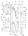
- FIG. 3 shows an AA cross-sectional view of the middle inclined groove 10 of FIG.
- the outer shallow bottom portion 12 is provided on the outer end 10 o side of the middle inclined groove 10.
- the outer shallow bottom portion 12 has a groove depth do smaller than the maximum groove depth dm of the middle inclined groove 10.
- Such an outer shallow bottom portion 12 reduces the influence of land portion rigidity reduction caused by the middle inclined groove 10 on the outer side of the middle land portion 6. Therefore, the outer shallow bottom portion 12 suppresses deformation of the middle land portion 6 at the time of turning, and consequently improves the steering stability.
- the groove depth do of the outer shallow bottom portion 12 is preferably as small as possible.
- the minimum groove depth do of the outer shallow bottom portion 12 is 45% or more, more preferably 50% or more of the maximum groove depth dm of the middle inclined groove 10, preferably 65% or less, More preferably, it is 60% or less.
- the outer shallow bottom portion 12 includes a base portion 12a extending in the groove length direction with a minimum groove depth do and an inclined portion 12b extending in the groove length direction so that the groove depth gradually increases from the base portion 12a. Contains.
- the inclined portion 12b is smoothly connected to the deepest portion 15 having the maximum groove depth dm. Such an inclined portion 12b can suppress an abrupt change in rigidity between the base portion 12a of the outer shallow bottom portion 12 and the deepest portion 15 and effectively prevent strain from being concentrated there.
- the outer shallow bottom portion 12 is provided in a certain range including the outer end 10o of the middle inclined groove 10. In order to sufficiently exhibit the above-described operation, it is desirable that the outer shallow bottom portion 12 is provided along the middle inclined groove 10 in a range of, for example, 4 to 8 mm.
- a sipe 13 extending along the middle inclined groove 10 is provided on the groove bottom surface of the outer shallow bottom portion 12.
- the sipe 13 has a cut shape with a width of 1 mm or less, for example. Even when the tread portion 2 is worn so that the outer shallow bottom portion 12 is in contact with the road surface, the sipe 13 allows the middle inclined groove 10 and the shoulder main groove 4 to communicate with each other, thereby preventing deterioration of drainage performance. Further, during traveling, the air compressed in the middle inclined groove 10 is discharged to the shoulder main groove 4 through the sipe 13. Therefore, the sipe 13 suppresses an increase in pumping noise or the like generated in the middle inclined groove 10.
- the sipe 13 preferably extends in the center position of the groove width of the outer shallow bottom portion 12.
- the depth of the sipe 13 is not particularly limited, for example, as shown in FIG. 3, it is desirable that the bottom portion 13 a of the sipe 13 reaches the position of the maximum groove depth dm of the middle inclined groove 10. Such a sipe 13 can exert the above-described action until the end of wear.
- the middle inclined groove 10 is provided with an inner shallow bottom portion 14 on the inner end 10i side.
- the inner shallow bottom portion 14 has a depth smaller than the maximum groove depth dm of the middle inclined groove 10. The inner shallow bottom portion 14 can further suppress the influence of the lowering of the rigidity of the middle land portion 6 due to the middle inclined groove 10 while ensuring the drainage performance in the middle inclined groove 10.
- the inner shallow bottom portion 14 has, for example, a smaller depth than the outer shallow bottom portion 12 or is larger along the groove length direction than the range of the outer shallow bottom portion 12. It is desirable to be formed.
- the groove depth di of the inner shallow bottom portion 14 is smaller than the groove depth do of the outer shallow bottom portion 12 and larger than the range of the outer shallow bottom portion 12 along the groove length direction.
- the groove depth di at the inner shallow bottom portion 14 is preferably as small as possible.
- the minimum groove depth di of the inner shallow bottom portion 14 is 10% or more, more preferably 15% or more of the maximum groove depth dm of the middle inclined groove 10, preferably 35% or less, More preferably, it is 30% or less.
- the inner shallow bottom portion 14 includes a base portion 14a extending in the groove length direction with a minimum groove depth di, and an inclined portion 14b extending in the groove length direction so that the groove depth gradually increases from the base portion 14a. Contains.
- the inclined portion 14 b is smoothly connected to the deepest portion 15. Such an inclined portion 14b can suppress an abrupt change in rigidity between the base portion 14a of the inner shallow bottom portion 14 and the deepest portion 15, and can effectively prevent the strain from being concentrated there.
- the inner shallow bottom portion 14 is provided in a certain range including the inner end 10 i of the middle inclined groove 10. In the preferred embodiment, the inner shallow bottom portion 14 is desirably provided in a range of 40 to 60% of the inner portion 10 b of the middle inclined groove 10.
- the deepest portion 15 of the middle inclined groove 10 is provided between the outer shallow portion 12 and the inner shallow portion 14. It is desirable that the deepest portion 15 has a maximum groove depth dm of, for example, about 65 to 100%, more preferably 70 to 90% of the groove depth of the center main groove 3.
- the deepest portion 15 of the middle inclined groove 10 is provided across, for example, both the outer portion 10a and the inner portion 10b of the middle inclined groove 10 (that is, including a bent portion).
- the inclined portion 14 b of the inner shallow bottom portion 14 has a gentler inclination than the inclined portion 12 b of the outer shallow bottom portion 12.
- the middle land portion 6 of the present embodiment is further provided with a plurality of slots 19.
- a plurality of slots 19 are provided in the tire circumferential direction at substantially the same pitch as the middle inclined groove 10.
- the slot 19 extends from the center main groove 3 in the tire axial direction and terminates in the middle land portion 6. In the preferred embodiment, the slot 19 extends at substantially the same angle as the outer portion 10 a of the middle inclined groove 10. Such a slot 19 maintains the rigidity of the middle land portion 6 inside and outside the tire in a well-balanced manner and suppresses the occurrence of uneven wear.
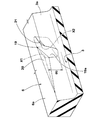
- FIG. 4 shows a partially enlarged perspective view of the middle land portion 6 on the inner side in the tire axial direction.
- the depth dc of the slot 19 is preferably determined within the same range as the maximum groove depth dm of the middle inclined groove 10, for example.
- a first chamfered portion 20 is provided at the corner portion X1 on the obtuse angle side where the slot 19 and the center main groove 3 intersect.
- the first chamfered portion 20 is a slope provided at a corner portion formed by the tread surface 6 a of the middle land portion 6, the groove wall surface 3 a of the center main groove 3, and the wall surface 19 a of the slot 19. As shown in FIG. 2, the width of the first chamfered portion 20 in the tire axial direction gradually decreases with increasing distance from the slot 19 so as to form a triangular shape in plan view. Such a first chamfered portion 20 can relieve stress concentration around the slot 19 and suppress the occurrence of rubber chipping and cracks there.
- a second chamfered portion 21 is provided at the corner portion X ⁇ b> 2 on the acute angle side where the slot 19 and the center main groove 3 intersect.
- the second chamfered portion 21 is a slope inclined inward in the tire radial direction from the tread surface 6a of the middle land portion 6 toward the tip of the corner portion X2.
- the second chamfered portion 21 is also formed in a triangular shape in plan view. Such a second chamfered portion 21 can also relieve stress concentration around the slot 19 and suppress the occurrence of rubber chipping and cracks there.
- a center land portion 5 is provided between the middle land portions 6 and 6.
- the configuration of the center land portion 5 is not particularly limited.
- the center land portion 5 is provided with a center lug groove 23.
- a plurality of center lug grooves 23 are provided in the tire circumferential direction at substantially the same pitch as the middle inclined groove 10 on each side of the center land portion 5.
- the center lug groove 23 extends from the center main groove 3 to the tire equator C side and terminates in the center land portion 5 without reaching the tire equator C.
- the center land portion 5 is formed as a rib extending continuously in the tire circumferential direction.
- the center lug groove 23 relaxes the tire circumferential rigidity of the center land portion 5 and approximates the tire circumferential direction rigidity of the middle land portion 6. Thereby, since the rigidity of the tread part 2 changes gradually from the tire equator C to the middle land part 6, the steering stability is further improved.
- the length L of the center lug groove 23 in the tire axial direction is desirably 30% or less of the width Wc of the center land portion 5.
- the depth of the center lug groove 23 is desirably determined within the same range as the maximum groove depth dm of the middle inclined groove 10, for example.
- a third chamfered portion 24 is provided at the corner portion X3 on the acute angle side where the center lug groove 23 and the center main groove 3 intersect.
- the third chamfered portion 24 is a slope inclined inward in the tire radial direction from the tread surface of the center land portion 5 toward the tip of the corner portion X3.
- the third chamfered portion 24 is formed in a triangular shape in plan view.
- Such a third chamfered portion 21 can alleviate stress concentration around the center lug groove 23 and suppress the occurrence of rubber chipping and cracks there.
- the shoulder land portion 7 is provided outside the middle land portion 6 in the tire axial direction.
- Each shoulder land portion 7 is provided with, for example, a plurality of shoulder lateral grooves 25.
- the shoulder lateral groove 25 extends from the shoulder main groove 4 to the tread grounding end Te.
- the shoulder land portion 7 is divided into a plurality of shoulder blocks 28.
- the shoulder lateral groove 25 extends substantially along the tire axial direction.
- it is desirable that the angle ⁇ 3 of the shoulder lateral groove 25 with respect to the tire circumferential direction is 80 to 90 degrees at the position of the tread ground contact edge Te.
- the shoulder lateral groove 25 of the present embodiment includes a first shoulder lateral groove 26 having a groove width G1 and a second shoulder lateral groove 27 having a groove width G2 smaller than the first shoulder lateral groove 26.
- the first shoulder lateral grooves 26 and the second shoulder lateral grooves 27 are preferably arranged alternately in the tire circumferential direction.
- Such an arrangement of the shoulder lateral grooves 25 can disperse pitch noise caused by the shoulder lateral grooves 25 in a wide frequency band during running and provide good noise performance.
- the groove width G2 of the second shoulder lateral groove 27 is 70% to 90% of the groove width G1 of the first shoulder lateral groove 26. The degree is desirable.
- the total number of shoulder lateral grooves 25 on each side of the tire equator C is twice the total number of middle inclined grooves 10.
- the middle land portion 6 is provided with the middle inclined groove 10 at a relatively low density, thereby further increasing the rigidity of the middle land portion 6.
- the inner end of the first shoulder lateral groove 26 having a large groove width is provided at a position that is smoothly continuous with the middle inclined groove 10 via the shoulder main groove 4.
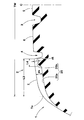
- FIG. 5 is a sectional view taken along the line BB of FIG.
- the shoulder lateral groove 25 includes a base portion 25a having a maximum groove depth ds and an inner shallow bottom portion 25b having a groove depth dt smaller than the maximum groove depth ds.
- the inner shallow bottom portion 25b is provided on the inner end side of the shoulder lateral groove 25 in the tire axial direction.
- the inner shallow bottom portion 25b suppresses deformation in the tire circumferential direction of each shoulder block 28 during driving braking while maintaining drainage, and effectively suppresses, for example, heel and toe wear (H / T wear). Can do.
- the depth dt of the inner shallow bottom 25b of the shoulder lateral groove 25 is preferably about 30% to 70% of the depth of the shoulder main groove 4.
- the length L4 of the inner shallow bottom portion 25b of the shoulder lateral groove 25 is preferably about 10% to 20% of the length L3 of the shoulder main groove 4 in the tire axial direction.
- FIG. 6 shows a partially enlarged perspective view of the shoulder land portion 7.
- the shoulder block 28 may be provided with a fourth chamfered portion 29.
- the fourth chamfered portion 29 is provided at a corner portion X4 formed by the shoulder lateral groove 25 on the first arrival side in the rotational direction R of the shoulder block 28 and the shoulder main groove 4.
- the fourth chamfered portion 29 is an inclined surface inclined inward in the tire radial direction from the tread surface of the shoulder block 28 toward the corner portion X4.
- the fourth chamfered portion 29 is formed in a triangular shape in plan view (FIG. 2).
- Such a 4th chamfer part 29 suppresses the deformation
- the fourth chamfered portion 29 can further suppress the occurrence of rubber chipping and cracks there.
- the shoulder block 28 may be provided with a fifth chamfered portion 30.
- the fifth chamfered portion 30 is provided at a corner portion X5 formed by the shoulder lateral groove 25 and the shoulder main groove 4 on the rearward side of the rotation direction R of the shoulder block 28.
- the fifth chamfered portion 30 is a slope inclined inward in the tire radial direction from the tread surface 28a of the shoulder block 28 toward the corner portion X5.
- the fifth chamfered portion 30 is formed on the rearward side of the rotation direction R of the fourth chamfered portion 29, and is longer in the tire circumferential direction than the fourth chamfered portion 29 in the plan view (FIG. 2) and is opposite to the reverse It is formed in a triangular shape.
- Such a fifth chamfered portion 30 suppresses deformation even when a large lateral force acts on the shoulder block 28 during turning, thereby improving the ground contact property of the shoulder block 28 and improving the steering stability.
- the tread portion 2 of the present embodiment has a substantially line-symmetric shape with respect to the tire equator C, but the tread half on one side of the tire equator C and the tread half on the other side of the tire equator C are A pattern shifted in the tire circumferential direction is employed. In such a pattern, the middle inclined grooves 10 and the shoulder lateral grooves 25 on both sides of the tire equator C are displaced from each other and contact with the road surface, so that even better noise performance can be obtained.
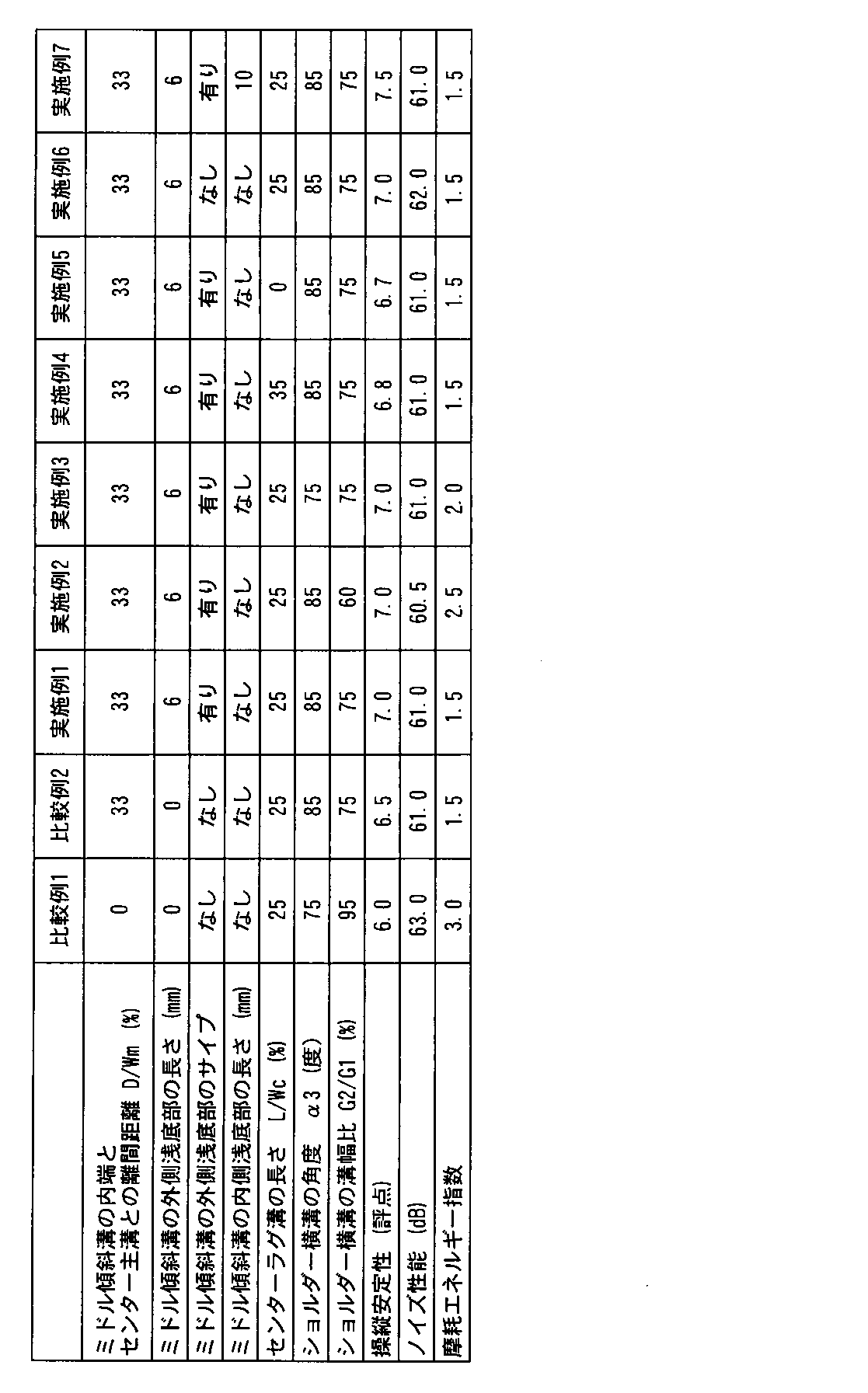
- radial tires for passenger cars of size 205 / 55R16 were prototyped based on the specifications in Table 1, and various performances were tested.
- the test method is as follows.
- OA value Passing noise
Abstract
Description
図1には、本発明の一実施形態の空気入りタイヤ1のトレッド部2の展開図が示されている。本実施形態の空気入りタイヤは、回転方向Rが指定された乗用車用のラジアルタイヤ1として実施されている。回転方向Rは、空気入りタイヤ1のサイドウォール部などに文字又は記号等を用いて表示される。
ショルダー横溝25は、最大溝深さdsを有する基部25aと、最大溝深さdsよりも小さい溝深さdtを有する内側浅底部25bとを含んでいる。内側浅底部25bは、ショルダー横溝25のタイヤ軸方向の内端側に設けられている。内側浅底部25bは、排水性を維持しながら駆動制動時での各ショルダーブロック28のタイヤ周方向の変形を抑制し、例えば、ヒールアンドトウ摩耗(H/T摩耗)を効果的に抑制することができる。
プロのテストドライバーが、下記条件でテストタイヤが装着された乗用車を、テストコースで運転し、各タイヤの操縦安定性を官能評価した。結果は、評点であり、数値が大きいほど良好である。
リムサイズ:6.6J
内圧:200kPa
上記乗用車を速度60km/hでアスファルト路を走行させたときの、通過騒音(O.A値)が測定された。数値が小さいほど良好である。
摩耗エネルギー試験機を用いて、ヒールアンドトウ摩耗(H/T摩耗)が測定された。結果は、摩耗エネルギー値の指数であり、数値が小さいほど良好である。
テストの結果等は表1に示される。
2 トレッド部
3 センター主溝
4 ショルダー主溝
5 センター陸部
6 ミドル陸部
7 ショルダー陸部
10 ミドル傾斜溝
12 外側浅底部
13 サイプ
14 内側浅底部
15 最深部
23 センターラグ溝
25 ショルダー横溝
26 第1ショルダー横溝
27 第2ショルダー横溝
dm 最大溝深さ
Claims (9)
- トレッド部に、タイヤ赤道の両側に配された一対のセンター主溝と、その両側に配された一対のショルダー主溝とが設けられることにより、タイヤ赤道の両側に、前記センター主溝と前記ショルダー主溝との間で区分されたミドル陸部が設けられた空気入りタイヤであって、
前記各ミドル陸部には、複数本のミドル傾斜溝が設けられ、
前記各ミドル傾斜溝は、前記ショルダー主溝に連通しているタイヤ軸方向の外端からタイヤ赤道側にのび、かつ、タイヤ軸方向の内端が前記センター主溝に連通することなく終端し、
前記ミドル傾斜溝の前記外端側には、前記ミドル傾斜溝の最大溝深さよりも小さい溝深さを有する外側浅底部が設けられていることを特徴とする空気入りタイヤ。 - 前記ミドル傾斜溝の前記内端側には、前記ミドル傾斜溝の最大溝深さよりも小さい深さを有する内側浅底部が設けられている請求項1記載の空気入りタイヤ。
- 前記内側浅底部の深さは、前記外側浅底部の深さよりも小さい請求項2記載の空気入りタイヤ。
- 前記外側浅底部の溝底面には、前記ミドル傾斜溝に沿ってのびるサイプが設けられている請求項1乃至3のいずれかに記載の空気入りタイヤ。
- 前記トレッド部は、前記各ショルダー主溝の外側にショルダー陸部が設けられており、
前記各ショルダー陸部には、複数本のショルダー横溝が設けられており、
前記ショルダー横溝は、第1ショルダー横溝と、前記第1ショルダー横溝よりも溝幅が小さい第2ショルダー横溝とを含み、
前記第1ショルダー主溝と前記第2ショルダー主溝とがタイヤ周方向に交互に配されている請求項1乃至4のいずれかに記載の空気入りタイヤ。 - 前記第2ショルダー横溝の溝幅は、前記第1ショルダー横溝の溝幅の70%~90%である請求項5記載の空気入りタイヤ。
- 前記ショルダー横溝は、前記トレッド部の接地端までのびており、
前記ショルダー横溝の前記接地端でのタイヤ周方向に対する角度が80度以上である請求項5又は6記載の空気入りタイヤ。 - 前記トレッド部は、前記センター主溝間にセンター陸部が設けられており、
前記センター陸部は、前記センター主溝からのびかつタイヤ赤道に達することなく終端するセンターラグ溝が設けられたリブである請求項1乃至7のいずれかに記載の空気入りタイヤ。 - 前記センターラグ溝のタイヤ軸方向の長さは、前記センター陸部の幅の30%以下である請求項8記載の空気入りタイヤ。
Priority Applications (4)
| Application Number | Priority Date | Filing Date | Title |
|---|---|---|---|
| US15/114,158 US10279631B2 (en) | 2014-01-27 | 2014-12-01 | Pneumatic tire |
| CN201480072781.3A CN105899376B (zh) | 2014-01-27 | 2014-12-01 | 充气轮胎 |
| EP14880068.3A EP3093163B1 (en) | 2014-01-27 | 2014-12-01 | Pneumatic tire |
| RU2016133292A RU2664139C2 (ru) | 2014-01-27 | 2014-12-01 | Пневматическая шина |
Applications Claiming Priority (2)
| Application Number | Priority Date | Filing Date | Title |
|---|---|---|---|
| JP2014-012639 | 2014-01-27 | ||
| JP2014012639A JP5903113B2 (ja) | 2014-01-27 | 2014-01-27 | 空気入りタイヤ |
Publications (1)
| Publication Number | Publication Date |
|---|---|
| WO2015111302A1 true WO2015111302A1 (ja) | 2015-07-30 |
Family
ID=53681124
Family Applications (1)
| Application Number | Title | Priority Date | Filing Date |
|---|---|---|---|
| PCT/JP2014/081783 WO2015111302A1 (ja) | 2014-01-27 | 2014-12-01 | 空気入りタイヤ |
Country Status (6)
| Country | Link |
|---|---|
| US (1) | US10279631B2 (ja) |
| EP (1) | EP3093163B1 (ja) |
| JP (1) | JP5903113B2 (ja) |
| CN (1) | CN105899376B (ja) |
| RU (1) | RU2664139C2 (ja) |
| WO (1) | WO2015111302A1 (ja) |
Cited By (4)
| Publication number | Priority date | Publication date | Assignee | Title |
|---|---|---|---|---|
| JP2017039407A (ja) * | 2015-08-20 | 2017-02-23 | 住友ゴム工業株式会社 | タイヤ |
| WO2017145681A1 (ja) * | 2016-02-26 | 2017-08-31 | 横浜ゴム株式会社 | 空気入りタイヤ |
| WO2018015044A1 (de) * | 2016-07-21 | 2018-01-25 | Continental Reifen Deutschland Gmbh | Fahrzeugluftreifen |
| CN108349329A (zh) * | 2016-01-21 | 2018-07-31 | 横滨橡胶株式会社 | 充气轮胎 |
Families Citing this family (10)
| Publication number | Priority date | Publication date | Assignee | Title |
|---|---|---|---|---|
| JP6668782B2 (ja) * | 2016-01-26 | 2020-03-18 | 住友ゴム工業株式会社 | タイヤ |
| JP6819110B2 (ja) * | 2016-07-21 | 2021-01-27 | 住友ゴム工業株式会社 | タイヤ |
| JP6880789B2 (ja) * | 2017-02-02 | 2021-06-02 | 横浜ゴム株式会社 | 空気入りタイヤ |
| WO2018207112A1 (en) * | 2017-05-12 | 2018-11-15 | Pirelli Tyre S.P.A. | Tyre for vehicle wheels |
| JP6929188B2 (ja) * | 2017-10-13 | 2021-09-01 | Toyo Tire株式会社 | 空気入りタイヤ |
| EP3326841B1 (en) * | 2017-11-27 | 2020-01-08 | Nokian Renkaat Oyj | A groove arrangement of a tread for a tire or a tread band |
| JP6624216B2 (ja) * | 2018-02-05 | 2019-12-25 | 横浜ゴム株式会社 | 空気入りタイヤ |
| JP7268429B2 (ja) * | 2019-03-20 | 2023-05-08 | 住友ゴム工業株式会社 | タイヤ |
| JP7298354B2 (ja) | 2019-07-10 | 2023-06-27 | 横浜ゴム株式会社 | 空気入りタイヤ |
| DE102021209903A1 (de) * | 2021-09-08 | 2023-03-09 | Continental Reifen Deutschland Gmbh | Fahrzeugreifen |
Citations (10)
| Publication number | Priority date | Publication date | Assignee | Title |
|---|---|---|---|---|
| JPH05254312A (ja) * | 1992-03-16 | 1993-10-05 | Bridgestone Corp | 空気入りタイヤ |
| JP2001138716A (ja) * | 1999-11-17 | 2001-05-22 | Bridgestone Corp | 空気入りタイヤ |
| JP2004106747A (ja) * | 2002-09-19 | 2004-04-08 | Sumitomo Rubber Ind Ltd | 重荷重用タイヤ |
| JP2004210189A (ja) | 2003-01-07 | 2004-07-29 | Sumitomo Rubber Ind Ltd | 空気入りタイヤ |
| JP2010132236A (ja) * | 2008-12-08 | 2010-06-17 | Sumitomo Rubber Ind Ltd | 空気入りタイヤ |
| JP2012140091A (ja) * | 2010-12-29 | 2012-07-26 | Sumitomo Rubber Ind Ltd | 空気入りタイヤ |
| JP2013049325A (ja) * | 2011-08-30 | 2013-03-14 | Sumitomo Rubber Ind Ltd | 空気入りタイヤ |
| JP2013063701A (ja) * | 2011-09-16 | 2013-04-11 | Sumitomo Rubber Ind Ltd | 空気入りタイヤ |
| JP2013100020A (ja) * | 2011-11-08 | 2013-05-23 | Sumitomo Rubber Ind Ltd | 空気入りタイヤ |
| JP2013139194A (ja) * | 2011-12-29 | 2013-07-18 | Sumitomo Rubber Ind Ltd | 空気入りタイヤ |
Family Cites Families (7)
| Publication number | Priority date | Publication date | Assignee | Title |
|---|---|---|---|---|
| JP3482033B2 (ja) | 1994-07-04 | 2003-12-22 | 住友ゴム工業株式会社 | 空気入りタイヤ |
| JP4813492B2 (ja) * | 2005-08-23 | 2011-11-09 | 株式会社ブリヂストン | 空気入りタイヤ |
| JP4145341B1 (ja) * | 2007-03-30 | 2008-09-03 | 横浜ゴム株式会社 | 空気入りタイヤ |
| JP5140146B2 (ja) * | 2010-12-09 | 2013-02-06 | 住友ゴム工業株式会社 | 空気入りタイヤ |
| JP5395786B2 (ja) * | 2010-12-29 | 2014-01-22 | 住友ゴム工業株式会社 | 空気入りタイヤ |
| JP5438719B2 (ja) * | 2011-04-20 | 2014-03-12 | 住友ゴム工業株式会社 | 空気入りタイヤ |
| JP5391262B2 (ja) * | 2011-12-29 | 2014-01-15 | 住友ゴム工業株式会社 | 空気入りタイヤ |
-
2014
- 2014-01-27 JP JP2014012639A patent/JP5903113B2/ja active Active
- 2014-12-01 US US15/114,158 patent/US10279631B2/en active Active
- 2014-12-01 CN CN201480072781.3A patent/CN105899376B/zh active Active
- 2014-12-01 RU RU2016133292A patent/RU2664139C2/ru active
- 2014-12-01 WO PCT/JP2014/081783 patent/WO2015111302A1/ja active Application Filing
- 2014-12-01 EP EP14880068.3A patent/EP3093163B1/en active Active
Patent Citations (10)
| Publication number | Priority date | Publication date | Assignee | Title |
|---|---|---|---|---|
| JPH05254312A (ja) * | 1992-03-16 | 1993-10-05 | Bridgestone Corp | 空気入りタイヤ |
| JP2001138716A (ja) * | 1999-11-17 | 2001-05-22 | Bridgestone Corp | 空気入りタイヤ |
| JP2004106747A (ja) * | 2002-09-19 | 2004-04-08 | Sumitomo Rubber Ind Ltd | 重荷重用タイヤ |
| JP2004210189A (ja) | 2003-01-07 | 2004-07-29 | Sumitomo Rubber Ind Ltd | 空気入りタイヤ |
| JP2010132236A (ja) * | 2008-12-08 | 2010-06-17 | Sumitomo Rubber Ind Ltd | 空気入りタイヤ |
| JP2012140091A (ja) * | 2010-12-29 | 2012-07-26 | Sumitomo Rubber Ind Ltd | 空気入りタイヤ |
| JP2013049325A (ja) * | 2011-08-30 | 2013-03-14 | Sumitomo Rubber Ind Ltd | 空気入りタイヤ |
| JP2013063701A (ja) * | 2011-09-16 | 2013-04-11 | Sumitomo Rubber Ind Ltd | 空気入りタイヤ |
| JP2013100020A (ja) * | 2011-11-08 | 2013-05-23 | Sumitomo Rubber Ind Ltd | 空気入りタイヤ |
| JP2013139194A (ja) * | 2011-12-29 | 2013-07-18 | Sumitomo Rubber Ind Ltd | 空気入りタイヤ |
Cited By (12)
| Publication number | Priority date | Publication date | Assignee | Title |
|---|---|---|---|---|
| JP2017039407A (ja) * | 2015-08-20 | 2017-02-23 | 住友ゴム工業株式会社 | タイヤ |
| CN108349329A (zh) * | 2016-01-21 | 2018-07-31 | 横滨橡胶株式会社 | 充气轮胎 |
| CN108349329B (zh) * | 2016-01-21 | 2020-07-31 | 横滨橡胶株式会社 | 充气轮胎 |
| US11577551B2 (en) | 2016-01-21 | 2023-02-14 | The Yokohama Rubber Co., Ltd. | Pneumatic tire |
| WO2017145681A1 (ja) * | 2016-02-26 | 2017-08-31 | 横浜ゴム株式会社 | 空気入りタイヤ |
| CN108602389A (zh) * | 2016-02-26 | 2018-09-28 | 横滨橡胶株式会社 | 充气轮胎 |
| JPWO2017145681A1 (ja) * | 2016-02-26 | 2018-12-13 | 横浜ゴム株式会社 | 空気入りタイヤ |
| RU2704766C1 (ru) * | 2016-02-26 | 2019-10-30 | Дзе Йокогама Раббер Ко., Лтд. | Пневматическая шина |
| DE112017001006B4 (de) | 2016-02-26 | 2022-06-30 | The Yokohama Rubber Co., Ltd. | Luftreifen |
| US11472231B2 (en) | 2016-02-26 | 2022-10-18 | The Yokohama Rubber Co., Ltd. | Pneumatic tire |
| WO2018015044A1 (de) * | 2016-07-21 | 2018-01-25 | Continental Reifen Deutschland Gmbh | Fahrzeugluftreifen |
| US11254168B2 (en) | 2016-07-21 | 2022-02-22 | Continental Reifen Deutschland Gmbh | Vehicle tire |
Also Published As
| Publication number | Publication date |
|---|---|
| EP3093163A4 (en) | 2017-09-06 |
| EP3093163B1 (en) | 2020-02-05 |
| US20170008346A1 (en) | 2017-01-12 |
| RU2016133292A (ru) | 2018-03-05 |
| JP2015140046A (ja) | 2015-08-03 |
| CN105899376B (zh) | 2018-06-26 |
| RU2016133292A3 (ja) | 2018-06-14 |
| RU2664139C2 (ru) | 2018-08-15 |
| EP3093163A1 (en) | 2016-11-16 |
| CN105899376A (zh) | 2016-08-24 |
| JP5903113B2 (ja) | 2016-04-13 |
| US10279631B2 (en) | 2019-05-07 |
Similar Documents
| Publication | Publication Date | Title |
|---|---|---|
| JP5903113B2 (ja) | 空気入りタイヤ | |
| US10414211B2 (en) | Pneumatic tire | |
| JP6006772B2 (ja) | 空気入りタイヤ | |
| JP5890796B2 (ja) | 空気入りタイヤ | |
| JP5038739B2 (ja) | スタッドレスタイヤ | |
| JP5592783B2 (ja) | 空気入りタイヤ | |
| JP5883373B2 (ja) | 空気入りタイヤ | |
| JP6010704B2 (ja) | 空気入りタイヤ | |
| US9815335B2 (en) | Pneumatic tire | |
| US10300745B2 (en) | Pneumatic tire | |
| EP3135504B1 (en) | Heavy duty tire | |
| JP2010241267A (ja) | 空気入りタイヤ | |
| EP3115229B1 (en) | Heavy duty pneumatic tire | |
| JP6077934B2 (ja) | 空気入りタイヤ | |
| US10967684B2 (en) | Tire | |
| US10889150B2 (en) | Pneumatic tire | |
| JP6848359B2 (ja) | タイヤ | |
| WO2018225371A1 (ja) | 空気入りタイヤ | |
| JP5993400B2 (ja) | 空気入りタイヤ | |
| JP6312646B2 (ja) | 空気入りタイヤ | |
| JP6980446B2 (ja) | 空気入りタイヤ | |
| JP6383323B2 (ja) | 空気入りタイヤ | |
| JP6369603B1 (ja) | 空気入りタイヤ | |
| JP6369602B1 (ja) | 空気入りタイヤ | |
| JP6658934B2 (ja) | 重荷重用タイヤ |
Legal Events
| Date | Code | Title | Description |
|---|---|---|---|
| 121 | Ep: the epo has been informed by wipo that ep was designated in this application |
Ref document number: 14880068 Country of ref document: EP Kind code of ref document: A1 |
|
| WWE | Wipo information: entry into national phase |
Ref document number: 15114158 Country of ref document: US |
|
| NENP | Non-entry into the national phase |
Ref country code: DE |
|
| REEP | Request for entry into the european phase |
Ref document number: 2014880068 Country of ref document: EP |
|
| WWE | Wipo information: entry into national phase |
Ref document number: 2014880068 Country of ref document: EP |
|
| ENP | Entry into the national phase |
Ref document number: 2016133292 Country of ref document: RU Kind code of ref document: A |