WO2015111179A1 - スライダー組立機のカバー取付装置 - Google Patents
スライダー組立機のカバー取付装置 Download PDFInfo
- Publication number
- WO2015111179A1 WO2015111179A1 PCT/JP2014/051448 JP2014051448W WO2015111179A1 WO 2015111179 A1 WO2015111179 A1 WO 2015111179A1 JP 2014051448 W JP2014051448 W JP 2014051448W WO 2015111179 A1 WO2015111179 A1 WO 2015111179A1
- Authority
- WO
- WIPO (PCT)
- Prior art keywords
- cover
- slider
- handle
- column
- plate
- Prior art date
- Legal status (The legal status is an assumption and is not a legal conclusion. Google has not performed a legal analysis and makes no representation as to the accuracy of the status listed.)
- Ceased
Links
Images





Classifications
-
- A—HUMAN NECESSITIES
- A44—HABERDASHERY; JEWELLERY
- A44B—BUTTONS, PINS, BUCKLES, SLIDE FASTENERS, OR THE LIKE
- A44B19/00—Slide fasteners
- A44B19/42—Making by processes not fully provided for in one other class, e.g. B21D53/50, B21F45/18, B22D17/16, B29D5/00
-
- A—HUMAN NECESSITIES
- A44—HABERDASHERY; JEWELLERY
- A44B—BUTTONS, PINS, BUCKLES, SLIDE FASTENERS, OR THE LIKE
- A44B19/00—Slide fasteners
- A44B19/24—Details
- A44B19/26—Sliders
- A44B19/30—Sliders with means for locking in position
- A44B19/306—Sliders with means for locking in position in the form of a locking spring member actuated by the pull member
Definitions
- the present invention relates to a cover attaching device for attaching a cover of an assembly machine for assembling a slider for a slide fastener to a body.
- a slider for slide fastener As a slider for slide fastener, it has a fuselage, a handle, and a cover. The slider is assembled by attaching the cover to the fuselage with the handle placed on the fuselage, and then crimping the cover to the fuselage. Is common.
- a slider for a slide fastener a slider with an automatic stop device is known.
- a slider with an automatic stop device disclosed in Patent Document 1 is known.
- the slider includes a body 1, a cover 2, a spring 3, and a handle 4.
- the fuselage 1 has a guide groove 13 that guides the fastener element by connecting the upper wing plate 10 and the lower wing plate 11 with a guide column 12, and a notch that is opened at the rear portion of the upper wing plate 10 is formed.
- a support column 15 is provided at the front portion of the upper blade 10 and an engagement column 16 is provided at the rear portion.
- a spring mounting groove 17 is formed in the center of the upper blade 10 in the width direction. The front portion of the groove 17 continues to the support column 15, and the rear portion continues to the rear through the engagement column 16.
- the front part and the rear part are directions in which the slider moves along the fastener element. When the slider moves toward the rear part, the fastener element is separated, and when the slider moves toward the front part, the fastener element meshes.
- the cover 2 has a substantially box shape in which the upper surface plate 20, the front surface plate 21, the rear surface plate 22, and the both side surface plates 23 are long in the front-rear direction and the lower surface is opened, and a locking piece 24 is provided continuously to the lower end of the rear surface plate 22.
- the lower surface of both side plates 23 has a substantially circular arc shape as a cam surface 25, and stop pawls 26 are provided downward toward the rear.
- the spring 3 is fitted and attached to the spring mounting groove 17 of the body 1, and the end 3 a of the spring 3 protrudes rearward from the engaging column 16.
- the pull handle 4 has a shaft 4 a and is placed on the upper surface of the body 1 so that the shaft 4 a is positioned between the support column 15 and the engagement column 16.
- the cover 2 covers the column 15 and the engagement column 16 on the upper surface of the body 1 and is assembled so that the locking piece 24 is in contact with the lower surface of the rear end portion 3a of the spring 3. It can be swung up and down by caulking.
- the cover 2 attached to the fuselage 1 has an upper surface plate 20 parallel to the upper wing plate 10 of the fuselage 1, that is, the cover 2 is parallel to the fuselage 1.
- the cover 2 is swingably held by a spring 3 in a downward posture.
- the stop claw 26 protrudes from the claw hole 14 into the guide groove 13 of the fuselage 1, locks by interfering between fastener elements of a slide fastener (not shown), and the slider moves. Stop not to.
- the cover is lowered straight from above and assembled to the fuselage, and the cover is attached to the fuselage by tightening the cover. Because it can, the cover can be attached to the body in the correct posture.
- the cover 2 is assembled to the body 1 with the spring 3 and the handle 4 arranged on the body 1, and both side plates of the cover 2 are assembled. 23 is attached to the support 15 by crimping.
- the locking piece 24 of the cover 2 contacts the lower surface of the end 3 a of the spring 3, the cover 2 cannot be lowered straight and attached to the body 1. Therefore, the present applicant temporarily places the cover 2 diagonally so that the locking piece 24 does not interfere with the spring 3, moves the cover 2 obliquely upward, and moves the locking piece 24 to the end of the spring 3.
- the cover 2 is almost horizontal, the locking piece 24 is in contact with the lower surface of the end portion 3a on the spring 3, and the cover 2 is assembled to the body 1 so as to cover the support column 15 and the engagement column 16.
- the two side plates 23 are swaged to the column 15 so that the cover 2 is attached to the body 1.
- the present invention has been made in view of the above-described problems, and an object of the present invention is to provide a slider assembling machine that allows a cover to be attached to a trunk in a correct posture when assembling a slider including a trunk, a handle, a spring, and a cover.
- This is a cover mounting device.
- a slider of a slide fastener includes a body 1, a spring 3 and a handle 4 attached to the upper surface of the body 1, and a cover 2 attached to the upper surface of the body 1.
- the cover 2 includes a top plate 20, a front plate 21, a rear plate 22, both side plates 23, a locking piece 24 provided near the rear plate 22 of the cover 2, and a stop claw 26,
- a support column 15 and an engagement column 16 are formed on the upper surface of the body 1
- the cover 2 covers the support column 15 and the engagement column 16 of the fuselage 1 on the upper surface of the fuselage 1, the locking piece 24 is in contact with the lower surface of the end 3 a of the spring 3, and close to the front plate 21 of the side plates 23.
- a cover mounting device for a slider assembling machine for assembling a slider for a slide fastener that is movably mounted on the column 15 of the body 1
- the slider assembly machine has a temporary placement portion for the cover 2 in which the rear plate 22 is lower than the front plate 21 and temporarily places the cover 2 in an inclined posture on the body 1.
- a cover attaching device for a slider assembly machine comprising: a cover attaching portion for attaching both side plates 23 of the cover 2 assembled to the body 1 to the support column 15 of the body 1.
- the cover set 40 is lowered to a position facing the rear plate 22 of the cover 2 temporarily placed on the body 1 and moved in a direction toward the rear plate 22 to temporarily A cover pusher 42 for pressing the placed cover 2 and assembling the cover 2 to the body 1;
- a cover pusher pad 43 that descends to a position in contact with the upper surface plate 20 of the cover 2 assembled to the body 1;
- a cover positioning piece 44 that descends to a position in contact with the front plate 21 of the cover 2 assembled to the body 1 can be provided.
- the cover 2 can be positioned by the cover pressure pad 43 and the cover positioning piece 44, and the cover 2 can be correctly assembled
- FIG. when the cover 2 is attached to the support column 15 by the cover attaching portion, the upper surface plate 20 of the cover 2 can be pressed by the cover pressure pad 43, and the attaching operation is easy.
- the cover mounting portion can be provided with a cover crimping portion 50 for crimping both side plates 23 of the cover 2 assembled to the fuselage 1 to the column 15 of the fuselage 1.
- the cover 2 can be attached by crimping the both side plates 23 of the cover 2 to the support column 15.
- the cover assembly device for a slider assembly machine is characterized in that the slider assembly machine has a handle holder 45 for supporting a handle 4 attached to the body 1, and the handle holder 45 moves in the vertical direction. Change the posture of 4 A cover crimping portion 50 for crimping the slider cover 2 to the support column 15 of the body 1 and a handle receiving base 45 for changing the posture of the handle 4 at a position where the handle 4 does not interfere can be provided.
- the cover assembly device for a slider assembly machine includes a turntable 31 that intermittently rotates every predetermined angle, and a storage recess 31a that stores the body 1 in the turntable 31.
- the temporary placement portion of the cover 2 may be provided with a cover support member 39 that is in contact with the rear plate 22 of the cover 2 temporarily placed on the trunk 1 near the turntable rotation center of the storage recess 31a.
- the cover crimping portion 50 includes a pair of crimping punches 53 that move toward the rotation center from the outer peripheral side of the turntable 31 and perform the crimping operation on the cover 2.
- the caulking punch 53 can be moved up and down between a lower position where the both side plates 23 of the cover 2 are caulked to the column 15 of the body 1 and an upper position above the cover 2.
- the caulking punch 53 does not get in the way when the caulking operation is not performed.
- the cover 2 temporarily placed on the body 1 is pushed and assembled by the cover set portion 40, and in this state, the cover 2 can be attached to the support column 15 by the cover mounting portion, so the body 1, the handle 4, the spring 3, and the cover
- the cover 2 can be attached to the body 1 in a correct posture.
- the slider assembling machine of the present invention assembles sliders for slide fasteners shown in FIGS. 1, 2 and 3.
- the machine frame 30 includes a base 30a and the base.
- the center frame 30b provided in the center of 30a is provided.
- a device 36, a finished product inspection device 37, and a finished product discharge device 38 are attached at intervals in the rotation direction of the turntable 31.
- the turntable 31 has a disc shape, and has a plurality of body support portions, for example, storage recesses 31a, which are supported at the periphery of the turntable 31 so as not to move the slider body 1 at regular intervals in the rotation direction.
- the above slider assembly machine assembles the slider as follows.
- the turntable 31 is intermittently rotated so that one storage recess 31a is opposed to the body supply device 32, and the body 1 is supplied from the body supply device 32 to the storage recess 31a and stored.
- the housing recess 31 a in which the body 1 is housed by rotation of the turntable 31 is opposed to the spring supply device 33, and the spring 3 is supplied to the body 1 by the spring supply device 33 and inserted into the groove 17.
- the handle 4 is supplied to the body 1 by the handle supply device 34 and placed, the cover 2 is supplied to the body 1 by the cover supply device 35 and temporarily placed, and the cover 2 is mounted by the cover mounting device 36.
- the assembly is completed by attaching it to 1, and the slider is a finished product.
- the completed slider is detected by the finished product inspection device 37, and the finished product discharge device 38 sorts and discharges it from the storage recess 31a of the turntable 31 into a good product storage portion and a defective product storage portion (not shown).
- the storage recess 31 a of the turntable 31 opens on the upper surface 31 b of the turntable 31 and the outer peripheral surface 31 c on the side opposite to the rotation center.
- the body 1 is accommodated in the housing recess 31 a by placing the support column 15 (front part) on the outer peripheral surface 31 c side of the turntable 31 and the engaging column 16 (rear part) on the rotation center side of the turntable 31.
- the handle 4 is placed, and then the cover 2 is temporarily placed on the body 1.
- the handle 4 is placed on the body 1 such that the shaft 4 a is in contact with the support column 15 on the upper surface of the body 1 and the engagement column 16 and protrudes from the outer peripheral surface 31 c of the turntable 31.
- the temporary placement of the cover 2 is a front plate 21 (front portion) with respect to a horizontal posture in which the upper plate 20 (upper surface) of the cover 2 is parallel to the upper wing plate 10 (upper surface) of the fuselage 1. Is inclined lower than the rear plate 22 (rear part), the front plate 21 is in contact with the upper surface of the column 15, the inner side of the upper plate 20 is in contact with the upper surface of the engagement column 16, and the locking piece 24 is the end of the spring 3.
- the cover 2 is placed on the body 1 so as to be lower than the portion 3a and separated from the rear side (the rotation center side of the turntable 31).
- a temporary placement portion for the cover 2 is provided on the turntable 31.
- the temporary placement portion of the cover 2 has a cover support member 39 provided on the rear side of the body 1 of the storage recess 31 a of the turntable 31, that is, near the rotation center of the turntable 31.
- the cover support member 39 has a support portion 39a that contacts and supports a part of the cover 2 in an inclined manner.
- a part of the cover support member 39 is cut off in the support portion 39 a, and the cross section thereof is a tapered surface or an arcuate surface and is in contact with the arcuate portion or the edge of the cover 2.
- the rear plate 22 of the cover 2 is in contact with the support portion 39a of the cover support member 39 so that the cover 2 can be temporarily placed on the upper surface of the body 1 with the cover 2 tilted.
- the cover 2 can be temporarily placed on the upper surface of the body 1 by lowering the cover 2 toward the body 1 with the cover supply device 35.
- the cover attachment device 36 has a cover set portion 40 for attaching the cover 2 temporarily placed on the fuselage 1 in an inclined posture to the upper surface of the fuselage 1, and a cover attachment portion for attaching the assembled cover 2 to the fuselage. is doing.
- the cover mounting portion includes a cover crimping portion 50 that crimps both side plates 23 of the cover 2 to the column 15 of the body 1.
- the cover set unit 40 includes an elevating body 41 provided on the central frame 30b to be movable up and down, a cover pusher 42 provided on the elevating body 41 so as to be swingable, a cover pressure pad 43 provided on the elevating body 41 so as to be movable up and down, A cover positioning piece 44 and a handle holder 45 attached to the outer peripheral surface 31c of the turntable 31 so as to be movable up and down are provided.
- the cover caulking portion 50 includes a main body 51 attached to the base 30a, a punch attachment body 52 attached to the main body 51 so as to be movable up and down, and attached to the punch attachment body 52 in a horizontal direction toward the turntable 31.
- a pair of movable crimping punches 53 and a punch moving mechanism 54 for performing a crimping operation by moving the pair of crimping punches 53 in the horizontal direction are provided.
- the pair of caulking punches 53 can reciprocate from the outer peripheral side of the turntable (31) toward the center of rotation. The pair of caulking punches 53 moves up and down together with the punch mounting body 52.
- the caulking punch 53 includes a caulking position where the cover 2 is caulked by the caulking portion 53 a of the caulking punch 53 to the column 15 of the body 1 placed in the storage recess 31 a of the turntable 31, and a position above the column 15. Move up and down.
- the caulking portion 53 a has a protrusion, and the both side plates 23 of the cover 2 are pressed by the protrusion of the caulking portion 53 a to crimp the cover 2 to the column 15 of the body 1.
- the rotation center side in the direction connecting the rotation center of the turntable 31 and the outer peripheral surface 31c is the rear side
- the outer peripheral surface 30c side is the front side, that is, the front part of the body 1 is the front side
- the rear part of the body 1 is the rear side.
- the cover pusher 42 is located closer to the rear side than the rear surface plate 22 of the temporarily placed cover 2, and as shown in FIG. 7, is substantially at the same height as the rear surface plate 22 of the temporarily placed cover 2, that is, the rear surface plate 22.
- the cover is lowered to the cover pressing position opposite to.
- the cover pusher 42 swings (moves) in the direction toward the rear plate 22 of the cover 2 as shown by an arrow a at the cover pressing position, and pushes the cover 2 toward the front portion of the body 1.
- the cover pressure pad 43 has a lower surface 43a substantially horizontal, preferably horizontal, and is positioned above the upper surface plate 20 of the temporarily placed cover 2. Further, as shown in FIG. 7, the cover pressure pad 43 descends toward the upper surface plate 20 of the cover 2 that is correctly assembled to the upper surface of the body 1 in the state indicated by the phantom line, and the lower surface 43 a of the cover pressure pad 43. The cover 2 moves down to the cover pressing position where the upper surface plate 20 contacts.
- the cover positioning piece 44 is lowered to a positioning position where the cover contact surface 44a is in contact with the front plate 21 of the cover 2 that is correctly assembled to the body 1.
- the handle cradle 45 attached to the outer peripheral surface 31c of the turntable 31 is movable in the vertical direction, and moves to the upper position indicated by the phantom line in FIG. It swings and the posture of the handle 4 is tilted so that it is above the to-be-clamped portion 15 a of the support column 15.
- the posture of the handle 4 is changed by moving the handle base 45 supporting the handle 4 up and down. This prevents the handle 4 and the crimping punch 53 from interfering when the side plates 23 of the cover 2 are crimped by the pair of crimping punches 53 so that the handle 4 does not get in the way when crimping.
- the handle holder 45 may be attached to the machine frame 30 instead of a part of the turntable 31 and is provided in the slider assembling machine.
- the pair of caulking punches 53 includes a base portion 53b that is movably mounted in a horizontal direction along the guide groove 55 of the punch mounting body 52, and a tip portion 53c provided on the base portion 53b.
- the crimping part 53a is provided in the front part 53c.
- a pair of arms 56 are attached to the punch attachment body 52 with a vertical axis 57 so as to be swingable in the horizontal plane direction.
- the distal end portion of the arm 56 and the base portion 53b of the caulking punch 53 are connected so that the base portion 53b moves along the guide groove 55 when the arm 56 swings in the horizontal direction.
- a pin provided at the tip of the arm 56 is fitted and connected to the groove of the base 53b.
- a pair of caulking punches 53 is formed by attaching a tension spring 58 across the base end portions of the pair of arms 56 protruding from the punch mounting body 52 so that the base end portions of the pair of arms 56 are parallel to each other. Is kept in a separated state.
- a roller 59 is attached to the base end portion of the pair of arms 56.
- a cam body 60 is attached to the main body 51 so as to reciprocate in a direction toward the rotation center of the turntable 31.
- the cam body 60 has arcuate cam grooves 61 into which the respective rollers 59 are fitted, and the arms 56 are arranged in a direction in which the base ends thereof are separated by fitting the rollers 59 into the cam grooves 61. It swings.
- the pair of arms 56 swings in the direction in which the base ends thereof are separated, the pair of crimping punches 53 moves in the approaching direction and performs a crimping operation.
- the punch mounting body 52 When the crimping punch 53 is in the upper position, as shown in FIG. 6, the punch mounting body 52 is positioned closer to the upper side of the cam body 60 provided in the main body 51, and the roller 59 is positioned higher than the cam groove 61 of the cam body 60. Is off.
- the caulking punch 53 When the caulking punch 53 is in the caulking position, the punch mounting body 52 is the same height as the cam body 60, and the roller 59 is the same height as the cam groove 61.
- the caulking punch 53 is movable in the vertical direction and lowers the caulking punch 53 to the caulking position, but the caulking position becomes the lower position.
- a pair of caulking is achieved by moving the punch mounting body 52 downward to bring the caulking punch 53 into the caulking position (downward position) and moving the cam body 60 toward the punch mounting body 52.
- Both side plates 23 of the cover 2 correctly attached to the body 1 by the punch 53 can be crimped to the support column 15.
- the both side plates 23 of the cover 2 are crimped to the to-be-clamped portions 15 a of the support columns 15 by denting the side surface plates 23 by the caulking portions 53 a that protrude inward from the caulking punch 53 and have protrusions.
- the punch attachment body 52 has a recess 52 a on the side facing the turntable 31, and the punch attachment body 52 is mounted on the trunk 1 stored in the storage recess 31 a of the turntable 31. It does not interfere with the cradle 45.
- the cover pusher 42 is lowered to the cover pressing position, and the lower end portion 42 a of the cover pusher 42 is opposed to the rear plate 22 of the cover 2 temporarily placed on the body 1 in an inclined posture.
- the cover pusher 42 is swung in the direction of the arrow a and moved to push the cover 2 toward the front portion of the body 1.
- the cover 2 has the upper surface plate 20 along the upper surface of the engagement column 16, the front plate 21 moves along the upper surface of the support column 15 toward the front portion of the body 1, and the locking piece 24 is moved to the spring 3.
- the front plate 21 is removed from the upper surface of the support column 15, and the cover 2 covers the support column 15 and the engagement column 16 on the upper surface of the body 1 as shown in FIG. Is assembled to the upper surface of the body 1 so as to be in contact with the lower surface of the end 3 a of the spring 3. If it becomes the attitude
- the cover pressure pad 43 moves to a pressing position where the upper surface of the cover 2 is pressed, and the cover positioning piece 44 moves to a positioning position where the front of the cover 2 is pressed.
- the lower surface 43 a contacts the upper surface plate 20 of the cover 2, and the cover contact surface 44 a of the cover positioning piece 44 contacts the front plate 21 of the cover 2, thereby positioning the cover 2 in a posture that is correctly assembled to the body 1.
- the cover pusher 42 contacts the rear plate 22 of the cover 2 and the cover 2 is held by the body 1.
- the cover positioning piece 44 is raised and separated from the front plate 21 of the cover 2, the cover pusher 42 is separated from the rear plate 22 of the cover 2, and the handle cradle 45 is raised and moved upward.
- the handle 4 is swung in an upward posture so that the cover positioning piece 44 and the handle 4 do not interfere with the caulking operation of the cover 2.
- the pair of caulking punches 53 are moved to the caulking position of the cover 2, the cam body 60 is moved, and the pair of caulking punches 53 are moved in the approaching direction, so that the both side plates 23 of the cover 2 are caulked to the column 15. Fasten the cover 2 to the body 1 so that it can swing up and down.
- the cover pusher 42 and the cover pressure pad 43 are lifted and separated from the cover 2, and the handle holder 45 is lowered to bring the handle 4 into a horizontal posture in contact with the upper surface of the body 1.
- the pair of caulking punches 53 are moved in the separation direction and are raised to the standby position.
Landscapes
- Slide Fasteners (AREA)
- Automatic Assembly (AREA)
- Closures For Containers (AREA)
Abstract
胴体に停止爪が付いたカバーを取り付けできるスライダー組立機のカバー取付装置とする。スライダーの胴体(1)にスプリング(3)、引手(4)を置いた状態でカバー(2)の係止片(24)がスプリング(3)の端部(3a)の下面に接するように停止爪(26)が付いたカバー(2)を胴体(1)に組み付け、カバー(2)を胴体(1)の支柱(15)に移動自在に加締めたスライドファスナー用のスライダーを組み立てる際に、胴体(1)にカバー(2)を取り付ける装置であって、胴体(1)に、その係止片(24)がスプリング(3)の端部(3a)よりも下方の傾斜姿勢で仮置きしたカバー(2)を、胴体(1)に組み付けるカバーセット部(40)と、組み付けたカバー(2)を支柱(15)に加締めるカバー加締め部(50)を備え、胴体(1)にカバー(2)を取り付けできるようにする。
Description
本発明は、スライドファスナー用のスライダーを組み立てる組立機のカバーを胴体に取り付けるカバー取付装置に関する。
スライドファスナー用のスライダーとしては、胴体と引手とカバーを備え、胴体に引手を置いた状態でカバーを胴体に組み付けて、そのカバーを胴体に加締めることでカバーを胴体に取り付けてスライダーを組み立てるものが一般的である。
スライドファスナー用のスライダーとしては、自動停止装置付きのスライダーが知られている。
例えば、特許文献1に開示された自動停止装置付きのスライダーが知られている。
スライドファスナー用のスライダーとしては、自動停止装置付きのスライダーが知られている。
例えば、特許文献1に開示された自動停止装置付きのスライダーが知られている。
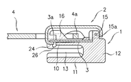
このスライダーは、図1及び図2に示すように、胴体1とカバー2とスプリング3と引手4を備えている。
胴体1は、上翼板10と下翼板11を案内柱12で連結してファスナーエレメントをガイドするガイド溝13を有し、上翼板10の後部に開口した切欠部が形成されて爪孔14としてある。
上翼板10の前部に支柱15、後部に係合柱16がそれぞれ設けてある。
上翼板10の幅方向中央にスプリング取付用の溝17が形成してある。この溝17の前部は支柱15まで連続し、後部は係合柱16を通して後方まで連続している。
前部、後部とはスライダーがファスナーエレメントに沿って移動する方向で、後部に向けて移動するとファスナーエレメントが分離し、前部に向けて移動するとファスナーエレメントが噛合する。
胴体1は、上翼板10と下翼板11を案内柱12で連結してファスナーエレメントをガイドするガイド溝13を有し、上翼板10の後部に開口した切欠部が形成されて爪孔14としてある。
上翼板10の前部に支柱15、後部に係合柱16がそれぞれ設けてある。
上翼板10の幅方向中央にスプリング取付用の溝17が形成してある。この溝17の前部は支柱15まで連続し、後部は係合柱16を通して後方まで連続している。
前部、後部とはスライダーがファスナーエレメントに沿って移動する方向で、後部に向けて移動するとファスナーエレメントが分離し、前部に向けて移動するとファスナーエレメントが噛合する。
カバー2は、上面板20と前面板21と後面板22と両側面板23とで前後方向に長く下面が開口した略箱形状で、後面板22の下端と連続して係止片24が設けてあり、両側面板23の下面を略円弧形状としてカム面25としてあると共に、後部寄りに停止爪26がそれぞれ下向きに設けてある。
スプリング3は胴体1のスプリング取付用の溝17に嵌合して取り付けて、そのスプリング3の端部3aが係合柱16から後方に向けて突出する。
引手4は軸4aを有し、その軸4aが支柱15と係合柱16との間に位置するように胴体1の上面に載置される。
カバー2は胴体1の上面に支柱15と係合柱16を覆うと共に、係止片24がスプリング3の後端部3aの下面に接するように組み付けられ、両側面板23の前部寄りを支柱15に加締めることで上下揺動自在に取り付ける。
胴体1に取り付けたカバー2は、その上面板20が胴体1の上翼板10と平行、つまりカバー2は胴体1と平行である。
スプリング3は胴体1のスプリング取付用の溝17に嵌合して取り付けて、そのスプリング3の端部3aが係合柱16から後方に向けて突出する。
引手4は軸4aを有し、その軸4aが支柱15と係合柱16との間に位置するように胴体1の上面に載置される。
カバー2は胴体1の上面に支柱15と係合柱16を覆うと共に、係止片24がスプリング3の後端部3aの下面に接するように組み付けられ、両側面板23の前部寄りを支柱15に加締めることで上下揺動自在に取り付ける。
胴体1に取り付けたカバー2は、その上面板20が胴体1の上翼板10と平行、つまりカバー2は胴体1と平行である。
カバー2はスプリング3で下向き姿勢に揺動して保持される。
カバー2が下向き姿勢であると、図2に示すように停止爪26が爪孔14から胴体1のガイド溝13に突出し、図示しないスライドファスナーのファスナーエレメント間に干渉してロックし、スライダーが移動しないように停止する。
カバー2が下向き姿勢であると、図2に示すように停止爪26が爪孔14から胴体1のガイド溝13に突出し、図示しないスライドファスナーのファスナーエレメント間に干渉してロックし、スライダーが移動しないように停止する。
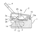
引手4を手で持って図3に示すように斜め上方に移動することで、引手4の軸4aがカバー2のカム面25に接してカバー2をスプリング3に抗して上向姿勢に揺動する。
カバー2が上向姿勢であると、停止爪26が胴体1のガイド溝13から抜け出し、スライダーは図示しないファスナーエレメントに沿って移動できる。
引手4から手を離すことで、スプリング3でカバー2が下向き姿勢に揺動するので、スライダーが移動しないように自動的に停止する。
カバー2が上向姿勢であると、停止爪26が胴体1のガイド溝13から抜け出し、スライダーは図示しないファスナーエレメントに沿って移動できる。
引手4から手を離すことで、スプリング3でカバー2が下向き姿勢に揺動するので、スライダーが移動しないように自動的に停止する。
前述した胴体、引手、カバーを備えた一般的なスライダーであれば、胴体に引手を設置した状態で上方からカバーを真直ぐ下降して胴体に組み付けて、カバーを加締めることでカバーを胴体に取り付けできるので、カバーを胴体に正しい姿勢で取り付けることができる。
前述した胴体、引手、スプリング、カバーを備えた自動停止装置付きのスライダーの場合には、胴体1にスプリング3、引手4を配置した状態でカバー2を胴体1に組み付けて、カバー2の両側面板23を支柱15に加締めて取り付けするが、カバー2の係止片24がスプリング3の端部3aの下面に接するので、カバー2を真直ぐ下降して胴体1に取り付けることができない。
そこで、本出願人は、係止片24がスプリング3と干渉しないようにしてカバー2を斜めに仮置きし、カバー2を斜め上方に向けて移動して係止片24をスプリング3の端部3aの下方に位置させ、カバー2をほぼ水平として係止片24をスプリング3に端部3aの下面に接し、かつ支柱15と係合柱16を覆うようにカバー2を胴体1に組み付け、カバー2の両側面板23を支柱15に加締めてカバー2を胴体1に取り付けるようにした。
そこで、本出願人は、係止片24がスプリング3と干渉しないようにしてカバー2を斜めに仮置きし、カバー2を斜め上方に向けて移動して係止片24をスプリング3の端部3aの下方に位置させ、カバー2をほぼ水平として係止片24をスプリング3に端部3aの下面に接し、かつ支柱15と係合柱16を覆うようにカバー2を胴体1に組み付け、カバー2の両側面板23を支柱15に加締めてカバー2を胴体1に取り付けるようにした。
しかしながら、カバー2を前述のように複雑に移動して組み付け、取り付けするので、カバー2と胴体1を組み付ける際に位置ずれし易く、カバー2を胴体1に正しい姿勢で取り付けることが困難であった。
本発明は、前述の課題に鑑みなされたものであり、その目的は、胴体と引手とスプリングとカバーを備えたスライダーを組み立てる際に、胴体にカバーを正しい姿勢で取り付けできるようにしたスライダー組立機のカバー取付装置とすることである。
本発明は、スライドファスナーのスライダーは、胴体1と、胴体1の上面に取り付けたスプリング3及び引手4と、胴体1の上面に取り付けたカバー2を備え、
前記カバー2は、上面板20と前面板21と後面板22と両側面板23と、このカバー2の後面板22寄りに設けた係止片24、停止爪26を有し、
胴体1の上面に支柱15と係合柱16を形成し、
前記カバー2は、胴体1の上面で、胴体1の支柱15、係合柱16を覆い、その係止片24がスプリング3の端部3aの下面に接し、かつ両側面板23の前面板21寄りが胴体1の支柱15に移動自在に取り付けられたスライドファスナー用のスライダーを組み立てるスライダー組立機のカバー取付装置であって、
前記スライダー組立機は、前記の胴体1に、後面板22が前面板21よりも低く、傾斜姿勢でカバー2を仮置きするカバー2の仮置き部を有し、
前記胴体1に、後面板22が前面板21よりも低く、係止片24がスプリング3の端部3aよりも下方である傾斜姿勢で仮置きしたカバー2を、胴体1の上面に組み付けるカバーセット部40と、
胴体1に組み付けたカバー2の両側面板23を胴体1の支柱15に取り付けるカバー取付け部と、を備えていることを特徴とするスライダー組立機のカバー取付装置である。
前記カバー2は、上面板20と前面板21と後面板22と両側面板23と、このカバー2の後面板22寄りに設けた係止片24、停止爪26を有し、
胴体1の上面に支柱15と係合柱16を形成し、
前記カバー2は、胴体1の上面で、胴体1の支柱15、係合柱16を覆い、その係止片24がスプリング3の端部3aの下面に接し、かつ両側面板23の前面板21寄りが胴体1の支柱15に移動自在に取り付けられたスライドファスナー用のスライダーを組み立てるスライダー組立機のカバー取付装置であって、
前記スライダー組立機は、前記の胴体1に、後面板22が前面板21よりも低く、傾斜姿勢でカバー2を仮置きするカバー2の仮置き部を有し、
前記胴体1に、後面板22が前面板21よりも低く、係止片24がスプリング3の端部3aよりも下方である傾斜姿勢で仮置きしたカバー2を、胴体1の上面に組み付けるカバーセット部40と、
胴体1に組み付けたカバー2の両側面板23を胴体1の支柱15に取り付けるカバー取付け部と、を備えていることを特徴とするスライダー組立機のカバー取付装置である。
本発明のスライダー組立機のカバー取付装置は、前記カバーセット部40は、胴体1に仮置きしたカバー2の後面板22と対向した位置まで下降し、後面板22に向かう方向に移動して仮置きしたカバー2を押して胴体1にカバー2を組み付けるカバープッシャ42と、
胴体1に組み付けたカバー2の上面板20に接する位置まで下降するカバープッシャパッド43と、
胴体1に組み付けたカバー2の前面板21と当接する位置まで下降するカバー位置決め片44を備えているものにできる。
胴体1に組み付けたカバー2の上面板20に接する位置まで下降するカバープッシャパッド43と、
胴体1に組み付けたカバー2の前面板21と当接する位置まで下降するカバー位置決め片44を備えているものにできる。
このようにすれば、カバープレッシャパッド43とカバー位置決め片44とでカバー2を位置決めし、胴体1にカバー2を正しく組み付けできる。
しかも、カバー取付部でカバー2を支柱15に取り付けるときに、カバープレッシャパッド43でカバー2の上面板20を押さえることができ、取り付け動作がやり易い。
しかも、カバー取付部でカバー2を支柱15に取り付けるときに、カバープレッシャパッド43でカバー2の上面板20を押さえることができ、取り付け動作がやり易い。
本発明のスライダー組立機のカバー取付装置は、カバー取付け部は、胴体1に組み付けたカバー2の両側面板23を胴体1の支柱15に加締めるカバー加締め部50を備えているものにできる。
このようにすれば、カバー2の両側面板23を支柱15に加締めることで、カバー2を取り付けできる。
本発明のスライダー組立機のカバー取付装置は、前記スライダー組立機は、胴体1に取り付けた引手4を支持する引手受台45を有し、前記引手受台45が上下方向に移動することで引手4の姿勢を変化させ、
スライダーのカバー2を胴体1の支柱15に加締めるカバー加締め部50と引手4が干渉しない位置に引手4の姿勢を変化させる引手受台45を備えているものにできる。
スライダーのカバー2を胴体1の支柱15に加締めるカバー加締め部50と引手4が干渉しない位置に引手4の姿勢を変化させる引手受台45を備えているものにできる。
このようにすれば、カバー2を加締めるときに引手4が邪魔にならない。
本発明のスライダー組立機のカバー取付装置は、前記スライダー組立機は、所定角度ごとに間欠回転するターンテーブル31と、ターンテーブル31に胴体1を収納する収納凹部31aを有し、
前記カバー2の仮置き部は、前記収納凹部31aのターンテーブル回転中心寄りに、胴体1に仮置きしたカバー2の後面板22が接するカバー支持部材39を設けたものにできる。
前記カバー2の仮置き部は、前記収納凹部31aのターンテーブル回転中心寄りに、胴体1に仮置きしたカバー2の後面板22が接するカバー支持部材39を設けたものにできる。
このようにすれば、胴体1に仮置きしたカバー2をカバー支持部39で支持することができる。
本発明のスライダー組立機のカバー取付装置は、前記カバー加締め部50は、ターンテーブル31の外周側から回転中心寄りに移動してカバー2を加締め動作する一対の加締パンチ53を備え、
前記加締パンチ53は、カバー2の両側面板23を胴体1の支柱15に加締める下方位置と、カバー2よりも上方の上方位置とに渡って上下移動自在とすることができる。
前記加締パンチ53は、カバー2の両側面板23を胴体1の支柱15に加締める下方位置と、カバー2よりも上方の上方位置とに渡って上下移動自在とすることができる。
このようにすれば、加締め動作しないときに加締めパンチ53が邪魔にならない。
本発明によれば、胴体1に仮置きしたカバー2をカバーセット部40で押して組み付け、その状態でカバー取付部でカバー2を支柱15に取り付けできるので、胴体1と引手4とスプリング3とカバー2を備えたスライダーを組み立てる際に、胴体1にカバー2を正しい姿勢で取り付けできる。
本発明のスライダー組立機は、図1、図2、図3に示すスライドファスナー用のスライダーを組み立てるもので、図4に概略的に示すように、機械フレーム30は基台30aと、この基台30aの中央に設けた中央フレーム30bを備えている。
中央フレーム30bに設けられ、所定角度ごとに矢印方向に間欠回転する回転盤であるターンテーブル31の周囲に、胴体供給装置32、スプリング供給装置33、引手供給装置34、カバー供給装置35、カバー取付装置36、完成品検査装置37、完成品排出装置38を、ターンテーブル31の回転方向に間隔を置いて取り付けてある。
ターンテーブル31は円盤状で、その周縁部にスライダーの胴体1を動かさないように支持する胴体支持部、例えば収納凹部31aを回転方向に等間隔で複数有している。
中央フレーム30bに設けられ、所定角度ごとに矢印方向に間欠回転する回転盤であるターンテーブル31の周囲に、胴体供給装置32、スプリング供給装置33、引手供給装置34、カバー供給装置35、カバー取付装置36、完成品検査装置37、完成品排出装置38を、ターンテーブル31の回転方向に間隔を置いて取り付けてある。
ターンテーブル31は円盤状で、その周縁部にスライダーの胴体1を動かさないように支持する胴体支持部、例えば収納凹部31aを回転方向に等間隔で複数有している。
前述のスライダー組立機はスライダーを次のようにして組み立てる。
ターンテーブル31を間欠回転して1つの収納凹部31aを胴体供給装置32と対向させ、その胴体供給装置32から胴体1を収納凹部31aに供給して収納する。
この後、ターンテーブル31の回転により胴体1が収納された収納凹部31aをスプリング供給装置33と対向させ、そのスプリング供給装置33で胴体1にスプリング3を供給して溝17に挿入する。
以下、同様にして引手供給装置34で胴体1に引手4を供給して載置し、カバー供給装置35でカバー2を胴体1に供給して仮置きし、カバー取付装置36でカバー2を胴体1に取り付けて組み立て完了し、完成品のスライダーとする。
この組立完了したスライダーを完成品検査装置37で検出し、完成品排出装置38でターンテーブル31の収納凹部31aから図示しない良品溜め部と不良品溜め部に選別して排出する。
ターンテーブル31を間欠回転して1つの収納凹部31aを胴体供給装置32と対向させ、その胴体供給装置32から胴体1を収納凹部31aに供給して収納する。
この後、ターンテーブル31の回転により胴体1が収納された収納凹部31aをスプリング供給装置33と対向させ、そのスプリング供給装置33で胴体1にスプリング3を供給して溝17に挿入する。
以下、同様にして引手供給装置34で胴体1に引手4を供給して載置し、カバー供給装置35でカバー2を胴体1に供給して仮置きし、カバー取付装置36でカバー2を胴体1に取り付けて組み立て完了し、完成品のスライダーとする。
この組立完了したスライダーを完成品検査装置37で検出し、完成品排出装置38でターンテーブル31の収納凹部31aから図示しない良品溜め部と不良品溜め部に選別して排出する。
図5に示すように、ターンテーブル31の収納凹部31aはターンテーブル31の上面31b及び回転中心と反対側の外周面31cに開口している。
胴体1は収納凹部31a内に、支柱15(前部)がターンテーブル31の外周面31c側で、係合柱16(後部)がターンテーブル31の回転中心側として置かれ収容される。
胴体1の溝17にスプリング3を挿入した後に引手4を載置し、その後にカバー2を胴体1に仮置きする。
引手4は軸4aが胴体1の上面の支柱15と係合柱16との間に接し、ターンテーブル31の外周面31cよりも突出して胴体1に載置される。
胴体1は収納凹部31a内に、支柱15(前部)がターンテーブル31の外周面31c側で、係合柱16(後部)がターンテーブル31の回転中心側として置かれ収容される。
胴体1の溝17にスプリング3を挿入した後に引手4を載置し、その後にカバー2を胴体1に仮置きする。
引手4は軸4aが胴体1の上面の支柱15と係合柱16との間に接し、ターンテーブル31の外周面31cよりも突出して胴体1に載置される。
カバー2の仮置きとは、図5に示すようにカバー2の上面板20(上面)が胴体1の上翼板10(上面)と平行である水平姿勢に対して前面板21(前部)が後面板22(後部)よりも低い傾斜姿勢で、前面板21が支柱15の上面に接すると共に、上面板20の内側が係合柱16の上面に接し、係止片24がスプリング3の端部3aよりも下方で、かつ後方側(ターンテーブル31の回転中心側)に離隔するようにしてカバー2を胴体1に置くことである。
ターンテーブル31にカバー2の仮置き部を設けてある。カバー2の仮置き部は、ターンテーブル31の収納凹部31aの胴体1よりも後側、つまりターンテーブル31の回転中心寄りに設けたカバー支持部材39を有している。
カバー支持部材39は、カバー2の一部に接触し傾斜支持する支持部39aを有する。支持部39aはカバー支持部材39の一部が切りかかれており、その断面はテーパー面や円弧状面であり、カバー2の円弧状部や縁部に接する。
そして、カバー2の後面板22をカバー支持部材39の支持部39aに接することで、カバー2を傾斜させた状態で胴体1の上面に仮置きできるようにしてある。
カバー支持部材39は、カバー2の一部に接触し傾斜支持する支持部39aを有する。支持部39aはカバー支持部材39の一部が切りかかれており、その断面はテーパー面や円弧状面であり、カバー2の円弧状部や縁部に接する。
そして、カバー2の後面板22をカバー支持部材39の支持部39aに接することで、カバー2を傾斜させた状態で胴体1の上面に仮置きできるようにしてある。
カバー供給装置35でカバー2を胴体1に向けて下降することによりカバー2を胴体1の上面に仮置きすることができる。
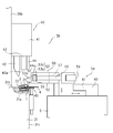
カバー取付装置36は、図6に示すように、胴体1に傾斜姿勢で仮置きしたカバー2を胴体1の上面に組み付けるカバーセット部40と、組み付けたカバー2を胴体に取り付けるカバー取付部を有している。カバー取付部は、カバー2の両側面板23を胴体1の支柱15に加締めるカバー加締め部50を備えている。
カバーセット部40は中央フレーム30bに上下動自在に設けた昇降体41と、この昇降体41に揺動自在に設けたカバープッシャ42、昇降体41に上下移動自在に設けたカバープレッシャパッド43、カバー位置決め片44と、ターンテーブル31の外周面31cに上下動自在に取り付けた引手受台45を備えている。
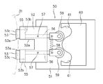
カバー加締め部50は基台30aに取り付けた本体51と、この本体51に上下動自在に取り付けたパンチ取付体52と、このパンチ取付体52に取り付けられてターンテーブル31に向かって水平方向に移動自在な一対の加締パンチ53と、一対の加締パンチ53を水平方向に移動して加締め動作するパンチ移動機構54を備えている。一対の加締パンチ53は、ターンテーブル(31)の外周側から回転中心寄りに往復し移動自在である。
一対の加締パンチ53はパンチ取付体52とともに上下に移動する。加締パンチ53は、ターンテーブル31の収納凹部31aに置かれた胴体1の支柱15に加締パンチ53の加締部53aでカバー2を加締める加締め位置と、支柱15よりも上方位置とに渡って上下方向に移動する。加締部53aは突起を有し、加締部53aの突起によってカバー2の両側面板23を押圧してカバー2を胴体1の支柱15に加締める。
一対の加締パンチ53はパンチ取付体52とともに上下に移動する。加締パンチ53は、ターンテーブル31の収納凹部31aに置かれた胴体1の支柱15に加締パンチ53の加締部53aでカバー2を加締める加締め位置と、支柱15よりも上方位置とに渡って上下方向に移動する。加締部53aは突起を有し、加締部53aの突起によってカバー2の両側面板23を押圧してカバー2を胴体1の支柱15に加締める。
カバーセット部40の詳細を説明する。なお、ターンテーブル31の回転中心と外周面31cを結ぶ方向の回転中心側を後側、外周面30c側を前側、つまり胴体1の前部を前側、胴体1の後部を後側として説明する。
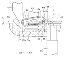
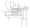
カバープッシャ42は、仮置きしたカバー2の後面板22よりも後側寄りに位置し、図7に示すように、仮置きしたカバー2の後面板22とほぼ同一高さ位置、つまり後面板22と対向したカバー押し位置まで下降する。
そして、カバープッシャ42はカバー押し位置において矢印aで示すように、カバー2の後面板22に向かう方向に揺動(移動)し、カバー2を胴体1の前部に向けて押す。
カバープッシャ42は、仮置きしたカバー2の後面板22よりも後側寄りに位置し、図7に示すように、仮置きしたカバー2の後面板22とほぼ同一高さ位置、つまり後面板22と対向したカバー押し位置まで下降する。
そして、カバープッシャ42はカバー押し位置において矢印aで示すように、カバー2の後面板22に向かう方向に揺動(移動)し、カバー2を胴体1の前部に向けて押す。
カバープレッシャパッド43は、下面43aがほぼ水平、好ましくは水平で、仮置きしたカバー2の上面板20の上方に位置する。また、カバープレッシャパッド43は、図7に示すように、仮想線で示す状態で胴体1の上面に正しく組み付けられたカバー2の上面板20に向かって下降し、カバープレッシャパッド43の下面43aとカバー2の上面板20が接するカバー押え位置まで下降する。
カバー位置決め片44の下部には、正しく組み付けたカバー2の前面板21とほぼ同一形状、好ましくは同一形状のカバー当接面44aを有している。
カバー位置決め片44は、そのカバー当接面44aが、胴体1に正しく組み付けたカバー2の前面板21と接する位置決め位置まで下降する。
カバー位置決め片44は、そのカバー当接面44aが、胴体1に正しく組み付けたカバー2の前面板21と接する位置決め位置まで下降する。
ターンテーブル31の外周面31cに取り付けられた引手受台45は上下方向に移動自在で、図7に仮想線で示す上方位置まで移動することで、引手4を仮想線で示すように上向き姿勢に揺動し、引手4の姿勢を傾斜させて支柱15の被加締部15aよりも上方とする。引手4を支持する引手受台45が上下に移動することによって、引手4の姿勢が変化する。これによって、一対の加締パンチ53でカバー2の両側面板23を加締めるときに引手4と加締パンチ53を干渉させず、加締時に引手4が邪魔にならないようにする。
なお、引手受台45はターンテーブル31の一部ではなく機械フレーム30に取り付けられていてもよく、スライダー組立機に設けられている。
なお、引手受台45はターンテーブル31の一部ではなく機械フレーム30に取り付けられていてもよく、スライダー組立機に設けられている。
カバー加締め部50の詳細を説明する。
図6及び図8に示すように、一対の加締パンチ53はパンチ取付体52のガイド溝55に沿って水平方向に移動自在に取り付けた基部53bと、この基部53bに設けた先部53cを備え、先部53cに加締部53aが設けてある。
パンチ取付体52には一対のアーム56が縦軸57で水平面方向に揺動自在に取り付けてある。
このアーム56の先端部と加締パンチ53の基部53bが、アーム56が水平方向に揺動することで基部53bがガイド溝55に沿って移動するように連結してある。例えば、アーム56の先端部に設けたピンを基部53bの溝に嵌合して連結してある。
図6及び図8に示すように、一対の加締パンチ53はパンチ取付体52のガイド溝55に沿って水平方向に移動自在に取り付けた基部53bと、この基部53bに設けた先部53cを備え、先部53cに加締部53aが設けてある。
パンチ取付体52には一対のアーム56が縦軸57で水平面方向に揺動自在に取り付けてある。
このアーム56の先端部と加締パンチ53の基部53bが、アーム56が水平方向に揺動することで基部53bがガイド溝55に沿って移動するように連結してある。例えば、アーム56の先端部に設けたピンを基部53bの溝に嵌合して連結してある。
このようであるから、アーム56を揺動することで一対の加締パンチ53は接近して加締め動作したり、離隔したりする。
一対のアーム56のパンチ取付体52よりも突出した基端部間に渡って引張スプリング58を取り付け、一対のアーム56の基端部を平行となるようにすることで、一対の加締めパンチ53を離隔した状態に保持している。
一対のアーム56の基端部にはローラ59が取り付けてある。
本体51にはカム体60がターンテーブル31の回転中心に向かう方向に往復移動自在に取り付けてある。このカム体60には各ローラ59が嵌まり込みする円弧状のカム溝61をそれぞれ有し、このカム溝61にローラ59が嵌まり込むことでアーム56は、その基端部が離れる方向に揺動するようにしてある。
一対のアーム56が、その基端部が離れる方向に揺動すると一対の加締パンチ53は接近方向に移動して加締め動作する。
一対のアーム56の基端部にはローラ59が取り付けてある。
本体51にはカム体60がターンテーブル31の回転中心に向かう方向に往復移動自在に取り付けてある。このカム体60には各ローラ59が嵌まり込みする円弧状のカム溝61をそれぞれ有し、このカム溝61にローラ59が嵌まり込むことでアーム56は、その基端部が離れる方向に揺動するようにしてある。
一対のアーム56が、その基端部が離れる方向に揺動すると一対の加締パンチ53は接近方向に移動して加締め動作する。
加締パンチ53が上方位置のときには図6に示すようにパンチ取付体52は本体51に設けたカム体60の上方寄りに位置し、ローラ59はカム体60のカム溝61よりも上方に位置がずれている。
加締パンチ53が加締め位置のときにはパンチ取付体52はカム体60と同一高さで、ローラ59がカム溝61と同一高さである。加締パンチ53は上下方向に移動可能であり加締パンチ53を加締め位置まで下降させるが、その加締め位置が下方位置となる。
この状態でカム体60をパンチ取付体52に向けて移動するとカム溝61がローラ59に向けて移動し、ローラ59とカム溝61が嵌まり合って図9に示すようにアーム56は、その基端部が離れる方向に揺動し、一対の加締パンチ53が接近する方向に移動する。
加締パンチ53が加締め位置のときにはパンチ取付体52はカム体60と同一高さで、ローラ59がカム溝61と同一高さである。加締パンチ53は上下方向に移動可能であり加締パンチ53を加締め位置まで下降させるが、その加締め位置が下方位置となる。
この状態でカム体60をパンチ取付体52に向けて移動するとカム溝61がローラ59に向けて移動し、ローラ59とカム溝61が嵌まり合って図9に示すようにアーム56は、その基端部が離れる方向に揺動し、一対の加締パンチ53が接近する方向に移動する。
このようであるから、パンチ取付体52を下方に移動して加締パンチ53を加締め位置(下方位置)とし、カム体60をパンチ取付体52に向けて移動することで、一対の加締パンチ53により胴体1に正しく取り付けられたカバー2の両側面板23を支柱15に加締めることができる。カバー2の両側面板23は、加締パンチ53から内側に突出して突起を有する加締部53aによって両側面板23を凹ませて支柱15の被加締部15aに加締められる。
図8に示すように、パンチ取付体52はターンテーブル31に向かう側に凹部52aを有し、パンチ取付体52がターンテーブル31の収納凹部31aに収納した胴体1に載置した引手2及び引手受台45と干渉しないようにしてある。
次に、胴体1にカバー2を正しく組み付ける動作を説明する。
図10に示すように、カバープッシャ42をカバー押し位置まで下降し、その下端部42aを胴体1に傾斜姿勢で仮置きしたカバー2の後面板22と対向する。
この状態でカバープッシャ42を矢印a方向に揺動し移動することで、カバー2を胴体1の前部に向けて押す。
これにより、カバー2は、上面板20が係合柱16の上面に沿うと共に、前面板21が支柱15の上面に沿って胴体1の前部に向けて移動し、係止片24がスプリング3の端部3aの下方に入り込み、前面板21が支柱15の上面から外れ、図11に示すようにカバー2が胴体1の上面で、支柱15及び係合柱16を覆うと共に、係合片24がスプリング3の端部3aの下面に接するように胴体1の上面に組み付けられる。このカバー2の姿勢となると、図7の仮想線と図11に示されているようにカバー2が胴体1に正しく組み付けられた状態となる。
図10に示すように、カバープッシャ42をカバー押し位置まで下降し、その下端部42aを胴体1に傾斜姿勢で仮置きしたカバー2の後面板22と対向する。
この状態でカバープッシャ42を矢印a方向に揺動し移動することで、カバー2を胴体1の前部に向けて押す。
これにより、カバー2は、上面板20が係合柱16の上面に沿うと共に、前面板21が支柱15の上面に沿って胴体1の前部に向けて移動し、係止片24がスプリング3の端部3aの下方に入り込み、前面板21が支柱15の上面から外れ、図11に示すようにカバー2が胴体1の上面で、支柱15及び係合柱16を覆うと共に、係合片24がスプリング3の端部3aの下面に接するように胴体1の上面に組み付けられる。このカバー2の姿勢となると、図7の仮想線と図11に示されているようにカバー2が胴体1に正しく組み付けられた状態となる。
この後に、図12に示すように、カバープレッシャパッド43がカバー2の上面を押さえる押え位置に移動すると共に、カバー位置決め片44がカバー2の前方を押える位置決め位置に移動し、カバープレッシャパッド43の下面43aがカバー2の上面板20に接すると共に、カバー位置決め片44のカバー当接面44aがカバー2の前面板21に当接することで、カバー2を胴体1に正しく組み付けた姿勢に位置決めする。
胴体1の上面でカバー2が正しく組み付けた姿勢となるときには、カバープレッシャパッド43の下面43aがカバー2の上面板20に接し、カバー位置決め片44のカバー当接面44aがカバー2の前面板21に当接し、カバープッシャ42がカバー2の後面板22に当接してカバー2が胴体1に保持される。
胴体1の上面でカバー2が正しく組み付けた姿勢となるときには、カバープレッシャパッド43の下面43aがカバー2の上面板20に接し、カバー位置決め片44のカバー当接面44aがカバー2の前面板21に当接し、カバープッシャ42がカバー2の後面板22に当接してカバー2が胴体1に保持される。
この後、図13に示すようにカバー位置決め片44を上昇させてカバー2の前面板21と離隔し、カバープッシャ42をカバー2の後面板22と離隔し、引手受台45を上昇させて上方位置とすることで、引手4を上向き姿勢に揺動して移動させ、カバー位置決め片44及び引手4がカバー2の加締め動作の邪魔にならないようにする。
一対の加締パンチ53をカバー2の加締め位置に移動し、カム体60を移動して一対の加締パンチ53を接近方向に移動することで、カバー2の両側面板23を支柱15に加締めてカバー2を胴体1に上下揺動自在に取り付ける。
カバー2の取り付けが完了したら、カバープッシャ42、カバープレッシャパッド43を上昇してカバー2と離隔し、引手受台45を下降して引手4を胴体1の上面に接した水平な姿勢とする。
これと同時に、一対の加締パンチ53を離隔方向に移動し、待機位置まで上昇する。
これと同時に、一対の加締パンチ53を離隔方向に移動し、待機位置まで上昇する。
1…胴体、2…カバー、3…スプリング、3a…端部、4…引手、4a…軸、15…支柱、15a…被加締め部、16…係合柱、20…上面板、21…前面板、22…後面板、23…両側面板、24…係止片、26…停止爪、31…ターンテーブル、31a…収納凹部、36…カバー取付装置、39…カバー支持部材、40…カバーセット部、42…カバープッシャ、43…カバープレッシャパッド、44…カバー位置決め片、45…引手受台、50…カバー加締め部、53…加締パンチ。
Claims (6)
- スライドファスナーのスライダーは、胴体(1)と、胴体(1)の上面に取り付けたスプリング(3)及び引手(4)と、胴体(1)の上面に取り付けたカバー(2)を備え、
前記カバー(2)は、上面板(20)と前面板(21)と後面板(22)と両側面板(23)と、このカバー(2)の後面板(22)寄りに設けた係止片(24)、停止爪(26)を有し、
胴体(1)の上面に支柱(15)と係合柱(16)を形成し、
前記カバー(2)は、胴体(1)の上面で、胴体(1)の支柱(15)、係合柱(16)を覆い、その係止片(24)がスプリング(3)の端部(3a)の下面に接し、かつ両側面板(23)の前面板(21)寄りが胴体(1)の支柱(15)に移動自在に取り付けられたスライドファスナー用のスライダーを組み立てるスライダー組立機のカバー取付装置であって、
前記スライダー組立機は、前記の胴体(1)に、後面板(22)が前面板(21)よりも低く、傾斜姿勢でカバー(2)を仮置きするカバー(2)の仮置き部を有し、
前記胴体(1)に、後面板(22)が前面板(21)よりも低く、係止片(24)がスプリング(3)の端部(3a)よりも下方である傾斜姿勢で仮置きしたカバー(2)を、胴体(1)の上面に組み付けるカバーセット部(40)と、
胴体(1)に組み付けたカバー(2)の両側面板(23)を胴体(1)の支柱(15)に取り付けるカバー取付け部と、を備えていることを特徴とするスライダー組立機のカバー取付装置。 - 前記カバーセット部(40)は、胴体(1)に仮置きしたカバー(2)の後面板(22)と対向した位置まで下降し、後面板(22)に向かう方向に移動して仮置きしたカバー(2)を押して胴体(1)にカバー(2)を組み付けるカバープッシャ(42)と、
胴体(1)に組み付けたカバー(2)の上面板(20)に接する位置まで下降するカバープッシャパッド(43)と、
胴体(1)に組み付けたカバー(2)の前面板(21)と当接する位置まで下降するカバー位置決め片(44)を備えている請求項1記載のスライダー組立機のカバー取付装置。 - カバー取付け部は、胴体(1)に組み付けたカバー(2)の両側面板(23)を胴体(1)の支柱(15)に加締めるカバー加締め部(50)を備えている請求項1又は2記載のスライダー組立機のカバー取付装置。
- 前記スライダー組立機は、胴体(1)に取り付けた引手(4)を支持する引手受台(45)を有し、前記引手受台(45)が上下方向に移動することで引手(4)の姿勢を変化させ、
スライダーのカバー(2)を胴体(1)の支柱(15)に加締めるカバー加締め部(50)と引手(4)が干渉しない位置に引手(4)の姿勢を変化させる引手受台(45)を備えている請求項3記載のスライダー組立機のカバー取付装置。 - 前記スライダー組立機は、所定角度ごとに間欠回転するターンテーブル(31)と、ターンテーブル(31)に胴体(1)を収納する収納凹部(31a)を有し、
前記カバー(2)の仮置き部は、前記収納凹部(31a)のターンテーブル回転中心寄りに、胴体(1)に仮置きしたカバー(2)の後面板(22)が接するカバー支持部材(39)を設けた請求項1又は2又は3又は4記載のスライダー組立機のカバー取付装置。 - 前記カバー加締め部(50)は、ターンテーブル(31)の外周側から回転中心寄りに移動してカバー(2)を加締め動作する一対の加締パンチ(53)を備え、
前記加締パンチ(53)は、カバー(2)の両側面板(23)を胴体(1)の支柱(15)に加締める下方位置と、カバー(2)よりも上方の上方位置とに渡って上下移動自在である請求項3又は4記載のスライダー組立機のカバー取付装置。
Priority Applications (3)
| Application Number | Priority Date | Filing Date | Title |
|---|---|---|---|
| CN201480002691.7A CN104755223B (zh) | 2014-01-24 | 2014-01-24 | 滑动件组装机的盖体安装装置 |
| PCT/JP2014/051448 WO2015111179A1 (ja) | 2014-01-24 | 2014-01-24 | スライダー組立機のカバー取付装置 |
| TW104100003A TWI547245B (zh) | 2014-01-24 | 2015-01-05 | 滑動件組裝機的蓋體安裝裝置 |
Applications Claiming Priority (1)
| Application Number | Priority Date | Filing Date | Title |
|---|---|---|---|
| PCT/JP2014/051448 WO2015111179A1 (ja) | 2014-01-24 | 2014-01-24 | スライダー組立機のカバー取付装置 |
Publications (1)
| Publication Number | Publication Date |
|---|---|
| WO2015111179A1 true WO2015111179A1 (ja) | 2015-07-30 |
Family
ID=53593835
Family Applications (1)
| Application Number | Title | Priority Date | Filing Date |
|---|---|---|---|
| PCT/JP2014/051448 Ceased WO2015111179A1 (ja) | 2014-01-24 | 2014-01-24 | スライダー組立機のカバー取付装置 |
Country Status (3)
| Country | Link |
|---|---|
| CN (1) | CN104755223B (ja) |
| TW (1) | TWI547245B (ja) |
| WO (1) | WO2015111179A1 (ja) |
Cited By (1)
| Publication number | Priority date | Publication date | Assignee | Title |
|---|---|---|---|---|
| CN109967685A (zh) * | 2019-04-16 | 2019-07-05 | 东莞卓众自动化科技有限公司 | 一种扳扣自动组装机 |
Citations (4)
| Publication number | Priority date | Publication date | Assignee | Title |
|---|---|---|---|---|
| JPS4886639A (ja) * | 1972-01-27 | 1973-11-15 | ||
| JPS4943446Y1 (ja) * | 1968-10-15 | 1974-11-28 | ||
| JPS6044611U (ja) * | 1983-09-02 | 1985-03-29 | ワイケイケイ株式会社 | 自動停止装置付きスライダ− |
| JPS61247402A (ja) * | 1984-09-28 | 1986-11-04 | 韓國ジツパ−株式会社 | フアスナ用スライダの連続組立装置 |
Family Cites Families (11)
| Publication number | Priority date | Publication date | Assignee | Title |
|---|---|---|---|---|
| US3964615A (en) * | 1974-07-01 | 1976-06-22 | Textron, Inc. | Apparatus for positioning sliders |
| JPH065066Y2 (ja) * | 1985-12-17 | 1994-02-09 | 吉田工業株式会社 | スライドフアスナ−用スライダ−組立機における部品取付装置 |
| JPH0857715A (ja) * | 1994-08-18 | 1996-03-05 | Hitachi Zosen Corp | 管体用の付属品位置決め装置 |
| JPH10129390A (ja) * | 1996-10-31 | 1998-05-19 | Nippon Plast Co Ltd | エアバッグ装置の製造装置 |
| JP2004358572A (ja) * | 2003-06-02 | 2004-12-24 | Fuji Heavy Ind Ltd | ワーク圧入方法及びワーク圧入装置 |
| CN201168870Y (zh) * | 2008-01-30 | 2008-12-24 | 陈曜田 | 拉链头的拉片组装机 |
| CN201220339Y (zh) * | 2008-05-27 | 2009-04-15 | 陈莹霜 | 拉链头自动铆压机 |
| CN201320679Y (zh) * | 2008-12-18 | 2009-10-07 | 黄玉珍 | 拉链头铆压装置及拉链头自动四点铆压机 |
| CN102210502B (zh) * | 2010-04-01 | 2014-10-22 | 福建浔兴拉链科技股份有限公司 | 止滑式拉链头 |
| CN102335820A (zh) * | 2010-07-16 | 2012-02-01 | 中国第一汽车集团公司 | 辅助分装设备 |
| CN201889628U (zh) * | 2010-11-24 | 2011-07-06 | 比亚迪股份有限公司 | 一种发动机共线分装设备 |
-
2014
- 2014-01-24 CN CN201480002691.7A patent/CN104755223B/zh active Active
- 2014-01-24 WO PCT/JP2014/051448 patent/WO2015111179A1/ja not_active Ceased
-
2015
- 2015-01-05 TW TW104100003A patent/TWI547245B/zh active
Patent Citations (4)
| Publication number | Priority date | Publication date | Assignee | Title |
|---|---|---|---|---|
| JPS4943446Y1 (ja) * | 1968-10-15 | 1974-11-28 | ||
| JPS4886639A (ja) * | 1972-01-27 | 1973-11-15 | ||
| JPS6044611U (ja) * | 1983-09-02 | 1985-03-29 | ワイケイケイ株式会社 | 自動停止装置付きスライダ− |
| JPS61247402A (ja) * | 1984-09-28 | 1986-11-04 | 韓國ジツパ−株式会社 | フアスナ用スライダの連続組立装置 |
Cited By (2)
| Publication number | Priority date | Publication date | Assignee | Title |
|---|---|---|---|---|
| CN109967685A (zh) * | 2019-04-16 | 2019-07-05 | 东莞卓众自动化科技有限公司 | 一种扳扣自动组装机 |
| CN109967685B (zh) * | 2019-04-16 | 2024-01-09 | 东莞卓众自动化科技有限公司 | 一种扳扣自动组装机 |
Also Published As
| Publication number | Publication date |
|---|---|
| TWI547245B (zh) | 2016-09-01 |
| CN104755223A (zh) | 2015-07-01 |
| TW201528996A (zh) | 2015-08-01 |
| CN104755223B (zh) | 2016-11-30 |
Similar Documents
| Publication | Publication Date | Title |
|---|---|---|
| KR101134611B1 (ko) | 압입기를 구비한 스냅링 자동조립체결장치 | |
| WO2015004763A1 (ja) | スライドファスナー用スライダー | |
| JPS637761B2 (ja) | ||
| KR20050080352A (ko) | 프레스 금형 | |
| WO2014076835A1 (ja) | スライダー組立機の胴体セット装置 | |
| US4750245A (en) | Gemstone mounting apparatus and method | |
| CN104755223B (zh) | 滑动件组装机的盖体安装装置 | |
| JP5859030B2 (ja) | ボタン取付装置及びボタン保持ダイ | |
| CN210388342U (zh) | 一种用于固定钉匣臂的夹持装置 | |
| WO2014181457A1 (ja) | スライダー組立機の引手保持装置 | |
| CN115644571B (zh) | 一种拉链头自动组装设备 | |
| WO2015068237A1 (ja) | カバーの板バネ取付装置 | |
| JPH0753124B2 (ja) | スライドファスナー用金属製務歯の取付装置 | |
| CN111644843B (zh) | 一种钩扣组装夹具及钩扣组装设备 | |
| US2997716A (en) | Hand attaching tool | |
| WO2014097424A1 (ja) | スライダー組立機のロックピン組付装置 | |
| KR102157737B1 (ko) | 계단형 비엠피시비 제조금형 및 이를 이용한 제조방법 | |
| JP2581570Y2 (ja) | 自動かしめ装置 | |
| JPH1110234A (ja) | プレス型 | |
| US20150089989A1 (en) | Metal Forming Head, A Machine With Such A Head And A Metal Forming Method | |
| JPS5856105Y2 (ja) | テイケツソウチ | |
| CN119658335B (zh) | 一种表带扣钉全自动组装设备 | |
| CN107205528B (zh) | 拉链用滑动件的组装装置 | |
| JPS6313213Y2 (ja) | ||
| CN211102527U (zh) | 一种文具夹自动组装设备的成品取出装置 |
Legal Events
| Date | Code | Title | Description |
|---|---|---|---|
| 121 | Ep: the epo has been informed by wipo that ep was designated in this application |
Ref document number: 14880197 Country of ref document: EP Kind code of ref document: A1 |
|
| DPE2 | Request for preliminary examination filed before expiration of 19th month from priority date (pct application filed from 20040101) | ||
| NENP | Non-entry into the national phase |
Ref country code: DE |
|
| 122 | Ep: pct application non-entry in european phase |
Ref document number: 14880197 Country of ref document: EP Kind code of ref document: A1 |
|
| NENP | Non-entry into the national phase |
Ref country code: JP |