WO2015098351A1 - Pompe d'alimentation en carburant à haute pression - Google Patents
Pompe d'alimentation en carburant à haute pression Download PDFInfo
- Publication number
- WO2015098351A1 WO2015098351A1 PCT/JP2014/080289 JP2014080289W WO2015098351A1 WO 2015098351 A1 WO2015098351 A1 WO 2015098351A1 JP 2014080289 W JP2014080289 W JP 2014080289W WO 2015098351 A1 WO2015098351 A1 WO 2015098351A1
- Authority
- WO
- WIPO (PCT)
- Prior art keywords
- valve
- fuel
- pressure
- relief
- supply pump
- Prior art date
Links
Images


Classifications
-
- F—MECHANICAL ENGINEERING; LIGHTING; HEATING; WEAPONS; BLASTING
- F02—COMBUSTION ENGINES; HOT-GAS OR COMBUSTION-PRODUCT ENGINE PLANTS
- F02M—SUPPLYING COMBUSTION ENGINES IN GENERAL WITH COMBUSTIBLE MIXTURES OR CONSTITUENTS THEREOF
- F02M59/00—Pumps specially adapted for fuel-injection and not provided for in groups F02M39/00 -F02M57/00, e.g. rotary cylinder-block type of pumps
- F02M59/44—Details, components parts, or accessories not provided for in, or of interest apart from, the apparatus of groups F02M59/02 - F02M59/42; Pumps having transducers, e.g. to measure displacement of pump rack or piston
- F02M59/447—Details, components parts, or accessories not provided for in, or of interest apart from, the apparatus of groups F02M59/02 - F02M59/42; Pumps having transducers, e.g. to measure displacement of pump rack or piston means specially adapted to limit fuel delivery or to supply excess of fuel temporarily, e.g. for starting of the engine
-
- F—MECHANICAL ENGINEERING; LIGHTING; HEATING; WEAPONS; BLASTING
- F02—COMBUSTION ENGINES; HOT-GAS OR COMBUSTION-PRODUCT ENGINE PLANTS
- F02M—SUPPLYING COMBUSTION ENGINES IN GENERAL WITH COMBUSTIBLE MIXTURES OR CONSTITUENTS THEREOF
- F02M59/00—Pumps specially adapted for fuel-injection and not provided for in groups F02M39/00 -F02M57/00, e.g. rotary cylinder-block type of pumps
- F02M59/44—Details, components parts, or accessories not provided for in, or of interest apart from, the apparatus of groups F02M59/02 - F02M59/42; Pumps having transducers, e.g. to measure displacement of pump rack or piston
- F02M59/46—Valves
-
- F—MECHANICAL ENGINEERING; LIGHTING; HEATING; WEAPONS; BLASTING
- F02—COMBUSTION ENGINES; HOT-GAS OR COMBUSTION-PRODUCT ENGINE PLANTS
- F02M—SUPPLYING COMBUSTION ENGINES IN GENERAL WITH COMBUSTIBLE MIXTURES OR CONSTITUENTS THEREOF
- F02M59/00—Pumps specially adapted for fuel-injection and not provided for in groups F02M39/00 -F02M57/00, e.g. rotary cylinder-block type of pumps
- F02M59/44—Details, components parts, or accessories not provided for in, or of interest apart from, the apparatus of groups F02M59/02 - F02M59/42; Pumps having transducers, e.g. to measure displacement of pump rack or piston
- F02M59/48—Assembling; Disassembling; Replacing
-
- F—MECHANICAL ENGINEERING; LIGHTING; HEATING; WEAPONS; BLASTING
- F04—POSITIVE - DISPLACEMENT MACHINES FOR LIQUIDS; PUMPS FOR LIQUIDS OR ELASTIC FLUIDS
- F04B—POSITIVE-DISPLACEMENT MACHINES FOR LIQUIDS; PUMPS
- F04B1/00—Multi-cylinder machines or pumps characterised by number or arrangement of cylinders
- F04B1/04—Multi-cylinder machines or pumps characterised by number or arrangement of cylinders having cylinders in star- or fan-arrangement
- F04B1/0404—Details or component parts
- F04B1/0452—Distribution members, e.g. valves
-
- F—MECHANICAL ENGINEERING; LIGHTING; HEATING; WEAPONS; BLASTING
- F04—POSITIVE - DISPLACEMENT MACHINES FOR LIQUIDS; PUMPS FOR LIQUIDS OR ELASTIC FLUIDS
- F04B—POSITIVE-DISPLACEMENT MACHINES FOR LIQUIDS; PUMPS
- F04B49/00—Control, e.g. of pump delivery, or pump pressure of, or safety measures for, machines, pumps, or pumping installations, not otherwise provided for, or of interest apart from, groups F04B1/00 - F04B47/00
- F04B49/02—Stopping, starting, unloading or idling control
- F04B49/03—Stopping, starting, unloading or idling control by means of valves
- F04B49/035—Bypassing
-
- F—MECHANICAL ENGINEERING; LIGHTING; HEATING; WEAPONS; BLASTING
- F04—POSITIVE - DISPLACEMENT MACHINES FOR LIQUIDS; PUMPS FOR LIQUIDS OR ELASTIC FLUIDS
- F04B—POSITIVE-DISPLACEMENT MACHINES FOR LIQUIDS; PUMPS
- F04B49/00—Control, e.g. of pump delivery, or pump pressure of, or safety measures for, machines, pumps, or pumping installations, not otherwise provided for, or of interest apart from, groups F04B1/00 - F04B47/00
- F04B49/22—Control, e.g. of pump delivery, or pump pressure of, or safety measures for, machines, pumps, or pumping installations, not otherwise provided for, or of interest apart from, groups F04B1/00 - F04B47/00 by means of valves
- F04B49/24—Bypassing
-
- F—MECHANICAL ENGINEERING; LIGHTING; HEATING; WEAPONS; BLASTING
- F04—POSITIVE - DISPLACEMENT MACHINES FOR LIQUIDS; PUMPS FOR LIQUIDS OR ELASTIC FLUIDS
- F04B—POSITIVE-DISPLACEMENT MACHINES FOR LIQUIDS; PUMPS
- F04B53/00—Component parts, details or accessories not provided for in, or of interest apart from, groups F04B1/00 - F04B23/00 or F04B39/00 - F04B47/00
- F04B53/16—Casings; Cylinders; Cylinder liners or heads; Fluid connections
-
- F—MECHANICAL ENGINEERING; LIGHTING; HEATING; WEAPONS; BLASTING
- F04—POSITIVE - DISPLACEMENT MACHINES FOR LIQUIDS; PUMPS FOR LIQUIDS OR ELASTIC FLUIDS
- F04B—POSITIVE-DISPLACEMENT MACHINES FOR LIQUIDS; PUMPS
- F04B53/00—Component parts, details or accessories not provided for in, or of interest apart from, groups F04B1/00 - F04B23/00 or F04B39/00 - F04B47/00
- F04B53/22—Arrangements for enabling ready assembly or disassembly
-
- F—MECHANICAL ENGINEERING; LIGHTING; HEATING; WEAPONS; BLASTING
- F02—COMBUSTION ENGINES; HOT-GAS OR COMBUSTION-PRODUCT ENGINE PLANTS
- F02M—SUPPLYING COMBUSTION ENGINES IN GENERAL WITH COMBUSTIBLE MIXTURES OR CONSTITUENTS THEREOF
- F02M2200/00—Details of fuel-injection apparatus, not otherwise provided for
- F02M2200/80—Fuel injection apparatus manufacture, repair or assembly
- F02M2200/8061—Fuel injection apparatus manufacture, repair or assembly involving press-fit, i.e. interference or friction fit
-
- F—MECHANICAL ENGINEERING; LIGHTING; HEATING; WEAPONS; BLASTING
- F02—COMBUSTION ENGINES; HOT-GAS OR COMBUSTION-PRODUCT ENGINE PLANTS
- F02M—SUPPLYING COMBUSTION ENGINES IN GENERAL WITH COMBUSTIBLE MIXTURES OR CONSTITUENTS THEREOF
- F02M59/00—Pumps specially adapted for fuel-injection and not provided for in groups F02M39/00 -F02M57/00, e.g. rotary cylinder-block type of pumps
- F02M59/02—Pumps specially adapted for fuel-injection and not provided for in groups F02M39/00 -F02M57/00, e.g. rotary cylinder-block type of pumps of reciprocating-piston or reciprocating-cylinder type
- F02M59/025—Pumps specially adapted for fuel-injection and not provided for in groups F02M39/00 -F02M57/00, e.g. rotary cylinder-block type of pumps of reciprocating-piston or reciprocating-cylinder type characterised by a single piston
-
- F—MECHANICAL ENGINEERING; LIGHTING; HEATING; WEAPONS; BLASTING
- F02—COMBUSTION ENGINES; HOT-GAS OR COMBUSTION-PRODUCT ENGINE PLANTS
- F02M—SUPPLYING COMBUSTION ENGINES IN GENERAL WITH COMBUSTIBLE MIXTURES OR CONSTITUENTS THEREOF
- F02M59/00—Pumps specially adapted for fuel-injection and not provided for in groups F02M39/00 -F02M57/00, e.g. rotary cylinder-block type of pumps
- F02M59/20—Varying fuel delivery in quantity or timing
- F02M59/36—Varying fuel delivery in quantity or timing by variably-timed valves controlling fuel passages to pumping elements or overflow passages
- F02M59/366—Valves being actuated electrically
- F02M59/368—Pump inlet valves being closed when actuated
-
- F—MECHANICAL ENGINEERING; LIGHTING; HEATING; WEAPONS; BLASTING
- F02—COMBUSTION ENGINES; HOT-GAS OR COMBUSTION-PRODUCT ENGINE PLANTS
- F02M—SUPPLYING COMBUSTION ENGINES IN GENERAL WITH COMBUSTIBLE MIXTURES OR CONSTITUENTS THEREOF
- F02M59/00—Pumps specially adapted for fuel-injection and not provided for in groups F02M39/00 -F02M57/00, e.g. rotary cylinder-block type of pumps
- F02M59/44—Details, components parts, or accessories not provided for in, or of interest apart from, the apparatus of groups F02M59/02 - F02M59/42; Pumps having transducers, e.g. to measure displacement of pump rack or piston
- F02M59/46—Valves
- F02M59/462—Delivery valves
Definitions
- the present invention relates to a high-pressure fuel supply pump suitable for use in a fuel supply system of an internal combustion engine provided with a high-pressure fuel injection valve that directly injects fuel into a cylinder.
- the high-pressure fuel volume is increased by the thermal expansion of the fuel accompanying the failure of the flow rate control mechanism of the intake valve, the discharge valve, or the temperature rise of the piping.
- a relief valve mechanism is provided to reduce the pressure in the high-pressure fuel volume chamber to a predetermined pressure or less and prevent failure of the high-pressure fuel injection valve and piping.
- This relief valve mechanism is configured such that the ball valve is pressed against the relief seat by the urging force of the spring, and the fuel flows only in one direction from the downstream side to the upstream side of the discharge valve. Further, when the set pressure determined by the set load of the spring exceeds the downstream pressure, the fuel is relieved upstream of the discharge valve. Furthermore, the relief valve mechanism is fixed to a relief flow path connecting the upstream side of the discharge valve and the downstream side of the discharge valve, and is inserted from the upstream side of the discharge valve toward the downstream side of the discharge valve.
- the pressure at the inlet side (downstream of the discharge valve) of the relief valve mechanism becomes high, and the differential pressure generated when the pressure at the outlet (upstream of the discharge valve) becomes low, the outlet (discharge) of the relief valve mechanism
- a force that pushes the relief valve mechanism acts in the direction upstream from the valve upstream side, that is, the direction opposite to the direction in which the relief valve mechanism is inserted, and the relief valve mechanism comes out.
- an object of the present invention is to increase the reliability of the unitized relief valve mechanism. .
- the above-mentioned object can be solved by devising a unitary relief valve mechanism insertion direction and regulation as an example.
- the reliability of the unitized relief valve mechanism can be enhanced.
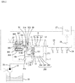
- 1 is an example of a fuel supply system using a high-pressure fuel supply pump according to a first embodiment in which the present invention is implemented.
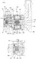
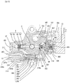
- 1 is an overall cross-sectional view of a high-pressure fuel supply pump according to a first embodiment in which the present invention is implemented.
- 1 is an overall longitudinal sectional view of a high-pressure fuel supply pump according to a first embodiment in which the present invention is implemented. It is an external view explaining the attachment state to the engine of the high pressure fuel supply pump of the 1st Example and 2nd Example by which this invention was implemented. It is a figure explaining the relief valve mechanism used for 1st Example and 2nd Example by which this invention was implemented. It is a figure explaining the electromagnetically driven suction valve mechanism used for the 1st Example and 2nd Example by which this invention was implemented. It is a whole cross-sectional view of the high-pressure fuel supply pump of the second embodiment in which the present invention is implemented.
- the pump housing 1 is provided with a cup-shaped recess 11A for forming the pressurizing chamber 11.
- a cylinder 6 is fitted into the opening of the recess 11A (pressurizing chamber 11). The end of the cylinder 6 is pressed against the stepped portion 16 ⁇ / b> A provided at the opening of the pressurizing chamber 11 of the pump housing 1 by the holder 7 by screwing the holder 7 with the screw portion 1 b.
- the cylinder 6 and the pump housing 1 are press-contacted by a stepped portion 16A to form a fuel seal portion by metal contact.
- the cylinder 6 is provided with a through hole (also referred to as a sliding hole) of the plunger 2 at the center.
- the plunger 2 is loosely fitted in the through hole of the cylinder 6 so as to be able to reciprocate.
- a seal ring 62 is attached to the outer periphery of the holder 7 at a position on the pressure chamber 11 side.
- the seal ring 62 forms a seal portion so that fuel does not leak between the outer periphery of the holder 7 and the inner peripheral wall of the recess 11 ⁇ / b> A of the pump housing 1.
- a double cylindrical portion of an inner cylindrical portion 71 and an outer cylindrical portion 72 is formed on the side of the holder 7 opposite to the cylinder 6.
- a plunger seal device 13 is held on the inner cylindrical portion 71 of the holder 7, and the plunger seal device 13 forms a fuel reservoir 67 between the inner periphery of the holder 7 and the peripheral surface of the plunger 2.
- the fuel reservoir 67 captures fuel leaking from the sliding surfaces of the plunger 2 and the cylinder 6.
- the plunger seal device 13 also prevents the lubricating oil from entering the fuel reservoir 67 from the cam 5 side described later.
- the outer cylindrical portion 72 formed on the side of the holder 7 opposite to the cylinder 6 is inserted into a mounting hole 100A formed in the engine block 100.
- a seal ring 61 is attached to the outer periphery of the annular protrusion 11 ⁇ / b> B of the pump housing 1. The seal ring 61 prevents lubricating oil from leaking into the atmosphere from the mounting hole 100A and prevents water from entering from the atmosphere.
- the high pressure fuel supply pump is fixed to the engine by a flange 41 and a bolt 42 that are integrally formed in the housing.
- the bolts 42 are screwed into respective screws formed on the engine side, and the flange 41 is pressed against the engine to fix the high-pressure fuel supply pump to the engine.
- the lower end surface 101A of the pump housing 1 is in contact with a flat surface 100B around the mounting hole 100A of the engine block.
- An annular protrusion 11B is formed at the center of the lower end surface 101A of the pump housing 1.
- the plunger 2 is formed such that the diameter of the small-diameter portion 2b extending from the cylinder to the counter-pressure chamber side is smaller than the diameter of the large-diameter portion 2a that slides on the cylinder 6. As a result, the outer diameter of the plunger seal device 13 can be reduced, and a space for forming the double cylindrical portions 71 and 72 in the holder 7 can be secured in this portion.
- a retainer 15 is fixed by a retainer holder 16 to the distal end portion of the small diameter portion 2b of the plunger 2 having a small diameter.
- a spring 4 is provided between the holder 7 and the retainer 15. One end of the spring 4 is attached to the inside of the outer peripheral cylindrical portion 72 around the inner peripheral cylindrical portion 71 of the holder 7. The other end of the spring 4 is disposed inside a retainer 15 made of a bottomed cylindrical metal.
- the cylindrical portion 31A of the retainer 15 is loosely fitted to the inner peripheral portion of the mounting hole 100A.
- the lower end 21A of the plunger 2 is in contact with the inner surface of the bottom 31B of the tappet 3.
- a rotating roller 3A is attached to the center of the bottom 31B of the tappet 3.
- the roller 3A is pressed against the surface of the cam 5 under the force of the spring 4.
- the cam 5 may be a two-leaf cam or a four-leaf cam in addition to the three-leaf cam (three cam mountains) shown in FIG.
- a damper cover 14 is fixed to the pump housing 1, and a pressure pulsation reducing mechanism 9 for reducing fuel pressure pulsation is provided in the low pressure chambers 10 c and 10 d defined between the damper cover 14 and the pump housing 1. Is housed.
- the pressure pulsation reducing mechanism 9 is provided with low-pressure chambers 10c and 10d on the upper and lower surfaces, respectively.
- the damper cover 14 has a function of forming low-pressure chambers 10c and 10d that accommodate the pressure pulsation reducing mechanism 9.
- the discharge port 12 shown in FIG. 2 is formed by a joint 103 fixed to the pump housing 1 by screwing or welding.
- the high-pressure fuel supply pump of the first embodiment has a fuel passage configuration from the low pressure fuel port 10a of the joint 101 to the low pressure fuel passage 10e, the low pressure chamber 10d, the suction passage 30a, the pressurization chamber 11 and the discharge port 12. Further, the low pressure chamber 10d, the low pressure fuel passage 10e, the annular low pressure passage 10h, the groove 7a provided in the holder 7, and the fuel reservoir 67 (annular low pressure chamber 10f) communicate with each other. As a result, when the plunger 2 reciprocates, the volume of the fuel reservoir 67 (annular low pressure chamber 10f) increases or decreases, and the fuel goes back and forth between the low pressure chamber 10d and the fuel reservoir 67 (annular low pressure chamber 10f). As a result, the heat of the fuel in the fuel reservoir 67 (annular low pressure chamber 10f) warmed by the sliding heat of the plunger 2 and the cylinder 6 is exchanged with the fuel in the low pressure chamber 10d and cooled.
- the electromagnetically driven suction valve mechanism 300 includes a plunger rod 301 that is electromagnetically driven.
- a valve 303 is provided at the tip of the plunger rod 301 and faces a valve seat 314 ⁇ / b> S formed in a valve housing 314 provided at an end of the electromagnetically driven intake valve mechanism 300.
- a plunger rod biasing spring 302 is provided at the other end of the plunger rod 301, and the valve 303 biases the plunger rod in a direction away from the valve seat 314S.
- a valve stopper S0 is fixed to the inner peripheral portion of the tip of the valve housing 314. The valve 303 is held between the valve seat 314S and the valve stopper S0 so as to be able to reciprocate.
- a valve urging spring S4 is disposed between the valve 303 and the valve stopper S0, and the valve 303 is urged away from the valve stopper S0 by the valve urging spring S4.
- valve 303 and the tip of the plunger rod 301 are biased by respective springs in opposite directions, but the plunger rod biasing spring 302 is configured with a stronger spring, so that the plunger rod 301 is biased by the valve.
- the valve 303 is pushed away from the valve seat against the urging force of the spring S4, and as a result, the valve 303 is pushed against the valve stopper S0.
- the plunger rod 301 opens the valve 303 via the plunger rod 301 by the plunger rod biasing spring 302 when the electromagnetically driven suction valve mechanism 300 is OFF (when the electromagnetic coil 304 is not energized). It is energizing in the direction of valve. Therefore, when the electromagnetically driven intake valve mechanism 300 is OFF, the plunger rod 301 and the valve 303 are maintained in the valve open position.
- a discharge valve unit 8 is provided at the outlet of the pressurizing chamber 11 (see FIG. 2).
- the discharge valve unit 8 includes a discharge valve seat 8a, a discharge valve 8b that contacts and separates from the discharge valve seat 8a, a discharge valve spring 8c that biases the discharge valve 8b toward the discharge valve seat 8a, a discharge valve 8b, and a discharge valve seat 8a. It is comprised from the discharge valve holder 8d which accommodates.
- a stepped portion 8f that forms a stopper that regulates the stroke of the discharge valve 8b is provided inside the discharge valve holder 8d.
- the discharge valve 8b In a state where there is no fuel differential pressure in the pressurizing chamber 11 and the discharge port 12, the discharge valve 8b is pressed against the discharge valve seat 8a by the urging force of the discharge valve spring 8c and is closed. Only when the fuel pressure in the pressurizing chamber 11 becomes higher than the fuel pressure in the discharge port 12, the discharge valve 8 b opens against the discharge valve spring 8 c, and the fuel in the pressurization chamber 11 opens the discharge port 12. After that, high pressure is discharged to the common rail as the high pressure volume chamber 23. When the discharge valve 8b is opened, it comes into contact with the discharge valve stopper 8f, and the stroke is limited. Accordingly, the stroke of the discharge valve 8b is appropriately determined by the discharge valve stopper 8d.
- the stroke is too large, and the fuel discharged at high pressure to the discharge port 12 due to the delay in closing the discharge valve 8b can be prevented from flowing back into the pressurizing chamber 11 again, and the decrease in efficiency of the high pressure pump is suppressed. it can.
- the discharge valve 8b repeats opening and closing movements, the discharge valve 8b is guided on the inner peripheral surface of the discharge valve holder 8d so as to move only in the stroke direction. By doing so, the discharge valve unit 8 becomes a check valve that restricts the direction of fuel flow.
- the pressurizing chamber 11 includes an electromagnetically driven suction valve mechanism 300, a discharge valve unit 8, a plunger 2, a cylinder 6, and a pump housing 1.
- the low pressure fuel supply pump 21 adjusts the intake fuel to the pump housing 1 to a constant pressure by a signal from the engine control unit 27 (hereinafter referred to as ECU).
- High pressure fuel pressurized in the pressurizing chamber through the path 1 is supplied from the discharge port 12 to the high pressure fuel volume chamber 23.
- a high pressure fuel injection valve 24 and a pressure sensor 26 are mounted in the high pressure fuel volume chamber 23.
- the high-pressure fuel injection valve 24 is mounted according to the number of cylinders of the internal combustion engine, and injects fuel into the combustion chamber of the internal combustion engine based on a signal from the ECU 27.
- the electromagnetically driven intake valve mechanism 300 includes a cup-shaped yoke 305 with a bottom that also serves as the body of the electromagnetically driven mechanism portion on the inner peripheral side of the annularly formed coil 304.
- a fixed core 306 and an anchor 307 are accommodated in an inner peripheral portion with a plunger rod biasing spring 302 interposed therebetween.
- the fixed core 306 is firmly fixed to the bottomed portion of the yoke 305 by press fitting.
- the anchor 307 is fixed to the end of the plunger rod 301 on the side opposite to the valve by press-fitting, and faces the fixed core 306 via a magnetic gap GP.
- the coil 304 is housed in a cup-shaped side yoke 304Y, and the inner peripheral surface of the open end portion of the side yoke 304Y is press-fitted and fitted to the outer peripheral portion of the annular flange portion 305F of the yoke 305, so that both are fixed. ing.
- a closed magnetic path CMP that crosses the magnetic gap GP is formed around the coil 304 by the yoke 305, the side yoke 304Y, the fixed core 306, and the anchor 307.
- the portion of the yoke 305 that faces the periphery of the magnetic gap GP is formed with a small thickness, and forms a magnetic aperture 305S. Thereby, the magnetic flux leaking through the yoke 305 decreases, and the magnetic flux passing through the magnetic gap GP can be increased.
- a valve housing 314 having a bearing portion 314B is fixed to the inner peripheral portion of the open side end cylindrical portion 305G of the yoke 305 by press fitting, and the plunger rod 301 has the bearing 314B. It penetrates and extends to the valve 303 provided at the inner periphery of the end of the valve housing 314 on the side opposite to the bearing 314B.
- a valve 303 is mounted between the tip of the plunger rod 301 and the valve stopper S0 so as to be able to reciprocate with a valve biasing spring S4 interposed therebetween.
- the valve 303 includes an annular surface portion 303R whose one surface faces a valve seat 314S formed on the valve housing 314 and whose other surface faces the valve stopper S0.
- a center portion of the annular surface portion 303R has a bottomed cylindrical portion extending to the tip of the plunger rod 301, and the bottomed cylindrical portion is composed of a bottom flat portion 303F and a cylindrical portion 303H.
- the cylindrical portion 303H protrudes into the low pressure fuel port 10a through the opening 314P formed in the valve housing 314 inside the valve seat 314S.
- the tip of the plunger rod 301 is in contact with the surface of the flat portion 303F at the plunger rod side end of the valve 303 at the low pressure fuel port 10a.
- Four fuel through holes 314Q are provided at equal intervals in the cylindrical portion between the bearing 314B and the opening 314P of the valve housing 314 in the circumferential direction.
- the four fuel passage holes 314Q communicate with the low-pressure fuel ports 10a inside and outside the valve housing 314.
- a cylindrical fuel introduction passage 10p connected to the annular fuel passage 10S between the valve seat 314S and the annular surface portion 303R is formed.
- the valve stopper S0 has a projecting portion ST having a cylindrical surface portion SG projecting toward the bottomed cylindrical portion of the valve 303 at the center of the annular surface portion S3, and the cylindrical surface portion SG has a stroke in the axial direction of the valve 303. It functions as a guide part for guiding.
- valve urging spring S4 is held between the valve side end surface SH of the projecting portion ST of the valve stopper S0 and the bottom surface of the bottomed cylindrical portion of the valve 303.
- the plunger rod 301 is attracted to the right in the drawing by electromagnetic force, so that the tip is separated from the flat surface portion 303F of the valve 303 and a gap is formed between them.
- the pressure in the low pressure fuel port 10a is replenished from the damper chamber 10d and the low pressure fuel port 10a as much as the volume of the annular low pressure chamber 10f is increased because the piston plunger 2 is rising from the bottom dead center.
- the pressure in the low-pressure fuel port 10a becomes lower than that when the volume of the tubular low-pressure chamber is reduced correspondingly.
- valve 303 is opened in the valve opening direction by the pressure difference between the static pressure of the fuel acting on the outer surface of the valve 303 represented by the flat surface portion 303F of the valve 303 located in the low pressure chamber 10d and the pressure of the fuel in the pressurized chamber. Receive power. Further, the fluid friction force generated between the fuel flow flowing into the pressurizing chamber 11 along the arrow R4 through the fuel introduction passage 10p and the peripheral surface of the cylindrical portion 303H of the valve 303 applies the valve 303 in the valve opening direction. Rush.
- valve 303 having a weight of several milligrams is quickly opened when the piston plunger 2 starts to descend by these urging forces, and strokes until it collides with the stopper ST.
- the plunger rod 301 and the anchor 307 are filled with the staying fuel, and the friction force with the bearing 314B acts, so that the plunger rod 301 and the anchor 307 are slightly faster than the valve 303 opening speed.
- the stroke to the left of the drawing is delayed.
- a slight gap is formed between the distal end surface of the plunger rod 301 and the flat portion 303F of the valve 303.
- the valve opening force provided from the plunger rod 301 falls for a moment.
- the valve force applied from the plunger rod 301 (plunger rod biasing spring 302) is reduced in the direction in which the valve 303 is opened.
- the fluid force of When the valve 303 is opened, the static pressure and dynamic pressure of the fluid act on the entire surface of the valve 303 on the low pressure chamber 10d side, so that the valve opening speed is increased.
- valve 303 When the valve 303 is opened, the inner peripheral surface of the cylindrical portion 303H of the valve 303 is guided by a valve guide formed by the cylindrical surface SG of the protruding portion ST of the valve stopper S0, and the valve 303 is not displaced in the radial direction. Stroke smoothly.
- the cylindrical surface SG forming the valve guide is formed on the upstream side and the downstream side with respect to the surface on which the valve seat 314 is arranged, so that it can sufficiently support the stroke of the valve 303 and also the inner peripheral side of the valve 303. Since the dead space can be effectively used, the axial dimension of the suction valve portion INV can be shortened.
- valve urging spring S4 is installed between the end surface SH of the valve stopper S0 and the bottom surface portion on the valve stopper S0 side of the flat surface portion 303F of the valve 303, it is between the opening 314P and the cylindrical portion 303H of the valve.
- the valve 303 and the valve urging spring S4 can be arranged inside the opening 314P while ensuring a sufficient passage area of the fuel introduction passage 10p formed in the opening 314P.
- the valve biasing spring S4 can be arranged by effectively utilizing the dead space on the inner peripheral side of the valve 303 located inside the opening 314P that forms the fuel introduction passage 10p, the dimension in the axial direction of the intake valve INV Can be shortened.
- the valve 303 has a valve guide (SG) at its center, and has an annular protrusion 303S that contacts the receiving surface S2 of the annular surface S3 of the valve stopper S0 on the outer periphery of the valve guide (SG). Further, a valve seat 314S is formed at a radially outer position, and the annular gap SGP is further formed to the radially outer side. Further, since the annular protrusion 303S that contacts the receiving surface S2 of the stopper S0 is provided inside the valve seat 314S inside the annular gap SGP, the fluid pressure on the pressure chamber side is applied to the annular gap SGP during the valve closing operation described later. It is possible to increase the valve closing speed when the valve 303 is pressed against the valve seat 314S by acting quickly.
- valve 303 and the stopper S0 are attracted by the fluid force that presses the valve 303 toward the stopper S0 by the dynamic pressure of the fuel flowing into the annular fuel passage 10S of the valve seat 314S and the suction effect of the fuel flow that flows around the outer periphery of the annular gap SGP.
- the valve 303 is firmly pressed against the stopper S0 by the fluid force acting on.
- the fuel in the pressurizing chamber 11 flows to the low-pressure fuel port 10a in the order of the annular fuel passage 10S and the fuel introduction passage 10P.
- the fuel flow path cross-sectional area of the fuel passage 10S is set smaller than the fuel flow path cross-sectional area of the fuel introduction path 10P. That is, the smallest fuel flow path cross-sectional area is set in the annular fuel path 10S. Therefore, pressure loss occurs in the annular fuel passage 10S and the pressure in the pressurizing chamber 11 starts to rise, but the fluid pressure is received by the annular surface of the stopper S0 on the pressurizing chamber side and hardly acts on the valve 303. .
- the fuel in the storage chamber 306K of the magnetic gap GP and the plunger rod biasing spring 302 is discharged from the fuel passage 314K to the low pressure passage through the periphery of the fuel passage 301K and the anchor 307.
- the anchor 307 and the plunger rod 301 are smoothly displaced toward the fixed core 306 side.
- the anchor 307 and the plunger rod 301 stop moving.
- the valve 303 Since the plunger rod 301 is attracted to the fixed core 306 and the urging force that presses the valve 303 against the stopper S0 side disappears, the valve 303 is urged away from the stopper S0 by the urging force of the valve urging spring S4. 303 starts the valve closing motion. At this time, the pressure in the annular gap SGP located on the outer peripheral side of the annular protrusion 303S becomes higher than the pressure on the low-pressure fuel port 10a side as the pressure in the pressurizing chamber 11 increases, and thus the valve 303 is closed. Help exercise. The valve 303 comes into contact with the seat 314S and the valve is closed. Since the piston plunger 2 continues to rise, the volume of the pressurizing chamber 11 decreases, and when the pressure in the pressurizing chamber 11 rises, the discharge valve unit 8 discharges high-pressure fuel.
- valve 303 When the valve 303 comes into contact with the seat 314S and is completely closed, the plunger rod 301 is completely drawn toward the fixed core 306 and the tip of the plunger rod 301 is separated from the end surface of the valve 303 on the low pressure fuel port 10a side. As a result, the valve 303 does not receive force from the plunger rod 301 in the counter-closing direction during the valve closing operation of the valve 303, so that the valve closing operation is accelerated. Further, since the valve 303 does not collide with the plunger rod 301 during the closing operation of the valve 303 and no striking sound is generated, a quiet valve mechanism can be obtained.
- valve 303 Since the valve closing force due to the pressure in the pressurizing chamber 11 is already sufficiently larger than the acting force of the plunger rod biasing spring 302, the valve 303 is opened even when the plunger rod 301 pushes the surface of the valve 303 on the low pressure port 10a side. There is no excuse.
- This state is a preparatory operation in which the plunger rod 301 urges the valve 303 in the valve opening direction at the moment when the piston plunger 2 turns from the top dead center toward the bottom dead center.
- the clearance between the plunger rod 301 and the side end surface of the valve 303 is a slight gap on the order of several tens to several hundreds of microns, and the valve 303 is urged by the pressure in the pressurizing chamber 11 so that the valve 303 becomes a rigid body. Therefore, the collision sound when the plunger rod 301 collides with the valve 303 does not become noise because its frequency is higher than the audible frequency and its energy is small.
- the fuel to be high-pressure fuel can be adjusted by controlling the timing of energizing the coil 304 based on a command from the engine control unit ECU. If the energization timing is controlled so that the valve 303 is closed immediately after the piston plunger 2 moves upward from the bottom dead center to the top dead center, the amount of fuel that is spilled and the amount of fuel that is discharged at high pressure increases. If the energization timing is controlled so that the valve 303 is closed immediately before the piston plunger 2 starts to move downward from the top dead center to the bottom dead center, more fuel is spilled and less fuel is discharged at high pressure.
- annular low pressure chamber 10f is provided between the lower end of the cylinder 6 and the plunger seal device 13, there is an annular low pressure chamber 10f as a fuel reservoir 67.
- the annular low pressure chamber 10f is provided in the low pressure chamber 10d-low pressure fuel passage 10e-annular low pressure passage 10h-holder 7.
- the groove 7 is opened and connected to the low pressure chamber 10d.
- the volume of the annular low pressure chamber 10f decreases, and the fuel in the annular low pressure chamber 10f flows through the low pressure passage 11e to the low pressure chamber 10d.
- the volume of the annular low pressure chamber 10f increases, and the fuel in the low pressure chamber 10d flows through the low pressure passage 11e to the annular low pressure chamber 10f.
- the annular low pressure chamber 10f has an effect of assisting fuel in and out of the low pressure chamber 10d, and thus has an effect of reducing pressure pulsation of the fuel generated in the low pressure chamber 10d.
- the low pressure chamber 10d upstream of the discharge valve unit 8 and downstream of the discharge valve unit 8 are connected by a relief passage 211-relief passage 210-relief passage 212-low pressure chamber 10d (not shown).
- the relief passage 210 has a relief passage opening 210 c different from the relief passage 211.
- the relief valve mechanism 200 is inserted into the relief passage 210 through the opening 210c, and the inner periphery of the relief passage 210 and the relief valve It press-fits with the housing press-fit part 206a.
- An abnormal high pressure in the high-pressure fuel volume chamber 23 caused by a failure of the high-pressure fuel injection device (23, 24, 30) for supplying fuel to the engine or a failure of the ECU 27 for controlling the high-pressure fuel supply pump or the like is caused by the relief valve 202.
- the set valve opening pressure is exceeded, the fuel reaches the relief valve 202 from the downstream side of the discharge valve 8b through the relief flow path 211. Then, the fuel that has passed through the relief valve 202 passes through the relief passage 212 from the escape passage 208 opened in the relief spring adjuster 205, and is released to the low pressure chamber 10d that is a low pressure portion.
- the high pressure portion such as the high pressure fuel volume chamber 23 is protected.
- the relief valve 202 is pressed against the relief valve seat 201 by a relief spring 204 that generates a pressing force.
- the set valve opening pressure is set so as to open the valve away from 201.
- the pressure when the relief valve 202 starts to open is defined as the set valve opening pressure.
- the relief valve mechanism 200 includes a relief valve housing 206, a relief valve 202, a relief press 203, a relief spring 204, and a relief spring adjuster 205 that are integral with the relief valve seat 201.
- the relief valve mechanism 200 is assembled as a subassembly outside the pump housing 1 and then fixed to the pump housing 1 by press fitting.
- the press-fitting sites are the inner peripheral part of the relief passage 210 and the relief valve housing press-fitting part 206a.
- the relief valve 202, the relief retainer 203, and the relief spring 204 are sequentially inserted into the relief valve housing 206 in this order, and the relief spring adjuster 205 is press-fitted and fixed to the relief valve housing 206.
- the set load of the relief spring 204 is determined by the fixed position of the relief spring adjuster 205.
- the valve opening pressure of the relief valve 202 is determined by the set load of the relief spring 204.
- the relief valve mechanism 200 thus assembled and unitized is inserted into a relief passage 210 provided in the pump housing 1 in order to insert the relief valve mechanism 200.
- the relief valve mechanism 200 is inserted until the outlet side comes into contact with the stepped portion 210b, and is fixed by press-fitting the relief valve housing 206a into the relief passage 210.
- the relief valve mechanism 200 is inserted from the outlet side of the relief valve mechanism 200.
- the press-fitting portion has a function of preventing high-pressure fuel downstream of the discharge valve unit 8 from flowing into the relief passage 212.
- the seal member 207 is fixed to the opening 210c by the screw portion 213, and the seat surface 207a of the seal member and the seat surface 210a of the relief passage opening are pressure-bonded by the thrust of the screw, and the high-pressure fuel is externally exposed. Seal against.
- the relief valve mechanism is provided in the relief passage 210. Since the inlet side of the relief valve mechanism 200 is downstream of the discharge valve unit 8, the pressure is high, and the outlet side is the discharge valve unit 8. Since it is on the upstream side, the pressure is low. Therefore, a force is generated from the inlet side to the outlet side of the relief valve mechanism 200 due to the differential pressure between the high pressure on the inlet side of the relief valve mechanism 200 and the low pressure on the outlet side. In this embodiment, since the outlet side of the relief valve mechanism 200 is in the same direction as the insertion direction, the relief valve mechanism 200 is in contact with the step portion 210b of the relief passage 210, and the step portion 210b serves as a stopper.
- the relief valve mechanism 200 does not come off, it does not come into contact with the seal member 207, and there is no risk of reducing the contact surface pressure between the seal member seat surface 207a and the seat surface 210a of the relief passage opening, and the sealing performance by the seal member 207 is reliable. Can increase the sex.
- the plunger 2 and the cylinder 6 repeat sliding movement when the internal combustion engine is operated.
- the clearance (gap) between the outer diameter of the large-diameter portion 2a of the plunger 2 that is the sliding portion and the inner diameter of the cylinder 6 is set to about 8 to 10 ⁇ m as an example. Normally, this clearance is filled with a thin film-like fuel, thereby ensuring smooth sliding. If the fuel thin film is interrupted for some reason, the plunger 2 and the cylinder 6 are locked and fixed during the sliding motion, so that there is a problem that the fuel cannot be pressurized to a high pressure.
- the high-pressure fuel supply pump pressurizes and discharges the fuel to a high pressure
- the pressure of the fuel in the pressurizing chamber 11 becomes high, and a very small high-pressure fuel is easily pumped to the annular low-pressure chamber 10f through the clearance. Therefore, it is difficult for a thin film of fuel to occur.
- the heat generated by the sliding movement of the plunger 2 and the cylinder 6 is also carried away by the pressurized high-pressure fuel to the outside of the high-pressure fuel supply pump, so that the fuel thin film in the clearance is vaporized due to the temperature rise. The thin film that occurs in the film does not break.
- the relief passage opening 210c is sealed by metal bonding the sheet surface 207a of the sealing member and the sheet surface 210a of the relief passage.
- the sealing structure includes the sealing member 207 and the relief passage opening 210c.
- a weld or gasket may be inserted into the relief passage opening 210c and may be sealed by pressing with metal.
- the fuel discharge port 12 is provided in the seal member 207, and the seal member 207 has both a function of discharging high-pressure fuel and a fuel seal function.
- the joint 103 does not have the fuel discharge port 12, and only has a function of sealing the fuel by plugging the insertion port provided in the pump housing 1 in order to insert the discharge valve unit 8.
- Other configurations are the same as those in the first embodiment. According to the present embodiment, the degree of freedom of layout of the fuel discharge port 12 is increased, and the attachment of the high-pressure fuel supply pump to the engine is improved.
- the difference from the first and second embodiments is that when an abnormally high pressure such as piping occurs, the high-pressure fuel passes through the relief passage 212 from the downstream side of the discharge valve unit 8 and is relieved to the pressurizing chamber 11. Is a point.
- Other configurations are the same as those in the first and second embodiments. According to this embodiment, the degree of freedom in processing the relief passage 212 can be increased.
Landscapes
- Engineering & Computer Science (AREA)
- Mechanical Engineering (AREA)
- General Engineering & Computer Science (AREA)
- Chemical & Material Sciences (AREA)
- Combustion & Propulsion (AREA)
- Fuel-Injection Apparatus (AREA)
Abstract
Priority Applications (5)
| Application Number | Priority Date | Filing Date | Title |
|---|---|---|---|
| US15/105,973 US10371109B2 (en) | 2013-12-27 | 2014-11-17 | High-pressure fuel supply pump |
| JP2015554675A JP6193402B2 (ja) | 2013-12-27 | 2014-11-17 | 高圧燃料供給ポンプ |
| CN201480071070.4A CN105849402B (zh) | 2013-12-27 | 2014-11-17 | 高压燃料供给泵 |
| EP14874606.8A EP3088726B1 (fr) | 2013-12-27 | 2014-11-17 | Pompe d'alimentation en carburant à haute pression |
| US16/449,771 US10683835B2 (en) | 2013-12-27 | 2019-06-24 | High-pressure fuel supply pump |
Applications Claiming Priority (2)
| Application Number | Priority Date | Filing Date | Title |
|---|---|---|---|
| JP2013270802 | 2013-12-27 | ||
| JP2013-270802 | 2013-12-27 |
Related Child Applications (2)
| Application Number | Title | Priority Date | Filing Date |
|---|---|---|---|
| US15/105,973 A-371-Of-International US10371109B2 (en) | 2013-12-27 | 2014-11-17 | High-pressure fuel supply pump |
| US16/449,771 Continuation US10683835B2 (en) | 2013-12-27 | 2019-06-24 | High-pressure fuel supply pump |
Publications (1)
| Publication Number | Publication Date |
|---|---|
| WO2015098351A1 true WO2015098351A1 (fr) | 2015-07-02 |
Family
ID=53478226
Family Applications (1)
| Application Number | Title | Priority Date | Filing Date |
|---|---|---|---|
| PCT/JP2014/080289 WO2015098351A1 (fr) | 2013-12-27 | 2014-11-17 | Pompe d'alimentation en carburant à haute pression |
Country Status (5)
| Country | Link |
|---|---|
| US (2) | US10371109B2 (fr) |
| EP (1) | EP3088726B1 (fr) |
| JP (1) | JP6193402B2 (fr) |
| CN (1) | CN105849402B (fr) |
| WO (1) | WO2015098351A1 (fr) |
Cited By (6)
| Publication number | Priority date | Publication date | Assignee | Title |
|---|---|---|---|---|
| JP2017066956A (ja) * | 2015-09-30 | 2017-04-06 | 日立オートモティブシステムズ株式会社 | 高圧燃料供給ポンプ |
| WO2017203861A1 (fr) * | 2016-05-27 | 2017-11-30 | 日立オートモティブシステムズ株式会社 | Pompe d'alimentation en carburant haute pression |
| CN108603477A (zh) * | 2016-02-03 | 2018-09-28 | 大陆汽车有限公司 | 高压燃料泵和燃料喷射系统 |
| US20190316558A1 (en) * | 2016-07-13 | 2019-10-17 | Hitachi Automotive Systems, Ltd. | High-Pressure Fuel Supply Pump |
| JP2020020342A (ja) * | 2015-08-28 | 2020-02-06 | 日立オートモティブシステムズ株式会社 | 高圧燃料ポンプ及びその製造方法 |
| US11459991B2 (en) * | 2017-09-29 | 2022-10-04 | Denso Corporation | High-pressure pump |
Families Citing this family (8)
| Publication number | Priority date | Publication date | Assignee | Title |
|---|---|---|---|---|
| JP6193402B2 (ja) * | 2013-12-27 | 2017-09-06 | 日立オートモティブシステムズ株式会社 | 高圧燃料供給ポンプ |
| DE102015205430A1 (de) * | 2015-03-25 | 2016-09-29 | Robert Bosch Gmbh | Elektromagnetisch betätigtes Mengensteuerventil, insbesondere zur Steuerung der Fördermenge einer Kraftstoff-Hochdruckpumpe |
| SE540744C2 (en) * | 2015-11-27 | 2018-10-30 | Scania Cv Ab | Method and system for determining pressure in a fuel accumulator tank of an engine |
| JP6586931B2 (ja) * | 2016-08-26 | 2019-10-09 | 株式会社デンソー | リリーフ弁装置、および、それを用いる高圧ポンプ |
| JPWO2018092538A1 (ja) * | 2016-11-18 | 2019-07-11 | 日立オートモティブシステムズ株式会社 | 高圧燃料供給ポンプ |
| DE102017202848A1 (de) * | 2017-02-22 | 2018-08-23 | Robert Bosch Gmbh | Kraftstoffhochdruckpumpe |
| CN110925048B (zh) * | 2019-12-12 | 2021-12-14 | 平湖市中美包装科技有限公司 | 一种汽车发动机转动部件润滑降温装置 |
| IT202000017767A1 (it) * | 2020-07-22 | 2022-01-22 | Marelli Europe Spa | Pompa carburante per un sistema di iniezione diretta |
Citations (7)
| Publication number | Priority date | Publication date | Assignee | Title |
|---|---|---|---|---|
| JP2004138062A (ja) | 2002-10-15 | 2004-05-13 | Robert Bosch Gmbh | 圧力制限弁及び該圧力制限弁を備えた燃料系 |
| JP2007138762A (ja) * | 2005-11-16 | 2007-06-07 | Hitachi Ltd | 高圧燃料供給ポンプ |
| JP2008064013A (ja) * | 2006-09-07 | 2008-03-21 | Hitachi Ltd | 高圧燃料供給ポンプ |
| JP2009534582A (ja) * | 2006-04-25 | 2009-09-24 | ローベルト ボツシユ ゲゼルシヤフト ミツト ベシユレンクテル ハフツング | 燃料高圧ポンプ |
| JP2010174903A (ja) * | 2010-05-17 | 2010-08-12 | Hitachi Automotive Systems Ltd | 高圧燃料供給ポンプ |
| JP2011179319A (ja) * | 2010-02-26 | 2011-09-15 | Hitachi Automotive Systems Ltd | 高圧燃料供給ポンプ |
| JP2012158990A (ja) * | 2011-01-28 | 2012-08-23 | Denso Corp | 高圧ポンプ |
Family Cites Families (22)
| Publication number | Priority date | Publication date | Assignee | Title |
|---|---|---|---|---|
| US2434137A (en) * | 1944-11-03 | 1948-01-06 | Zimmerman Harry | Xylophone |
| JP2000145591A (ja) * | 1998-09-01 | 2000-05-26 | Mitsubishi Electric Corp | 燃料供給装置 |
| JP2003247474A (ja) | 2002-02-20 | 2003-09-05 | Bosch Automotive Systems Corp | 高圧燃料ポンプ |
| JP4056366B2 (ja) * | 2002-11-20 | 2008-03-05 | 信越化学工業株式会社 | 塩化亜鉛担持体の製造方法 |
| JP2007120492A (ja) * | 2005-09-29 | 2007-05-17 | Denso Corp | 高圧燃料ポンプ |
| JP4437552B2 (ja) * | 2006-05-26 | 2010-03-24 | 株式会社デンソー | 高圧燃料ポンプ |
| JP2008057451A (ja) * | 2006-08-31 | 2008-03-13 | Hitachi Ltd | 高圧燃料供給ポンプ |
| JP4413260B2 (ja) * | 2007-10-12 | 2010-02-10 | 株式会社日本自動車部品総合研究所 | 高圧燃料ポンプ |
| JP5103138B2 (ja) | 2007-11-01 | 2012-12-19 | 日立オートモティブシステムズ株式会社 | 高圧液体供給ポンプ |
| JP4945504B2 (ja) | 2008-04-17 | 2012-06-06 | 日立オートモティブシステムズ株式会社 | 高圧燃料供給ポンプ |
| JP2011132941A (ja) | 2009-11-26 | 2011-07-07 | Nippon Soken Inc | 圧力制御弁 |
| JP4998837B2 (ja) * | 2009-12-10 | 2012-08-15 | 株式会社デンソー | 高圧ポンプ |
| JP5472395B2 (ja) * | 2010-06-29 | 2014-04-16 | 株式会社デンソー | 高圧ポンプ |
| JP5198511B2 (ja) * | 2010-06-29 | 2013-05-15 | 株式会社デンソー | 定残圧弁 |
| IT1401819B1 (it) | 2010-09-23 | 2013-08-28 | Magneti Marelli Spa | Pompa carburante per un sistema di iniezione diretta. |
| US8997716B2 (en) | 2010-11-15 | 2015-04-07 | Governors America Corp. | Controlled nozzle injection method and apparatus |
| JP5501272B2 (ja) * | 2011-03-08 | 2014-05-21 | 日立オートモティブシステムズ株式会社 | 高圧燃料供給ポンプ |
| JP5472751B2 (ja) | 2011-03-30 | 2014-04-16 | 株式会社デンソー | 高圧ポンプ |
| JP5589121B2 (ja) * | 2013-06-06 | 2014-09-10 | 日立オートモティブシステムズ株式会社 | 高圧燃料供給ポンプ |
| JP6193402B2 (ja) * | 2013-12-27 | 2017-09-06 | 日立オートモティブシステムズ株式会社 | 高圧燃料供給ポンプ |
| EP3088725B1 (fr) * | 2015-04-28 | 2019-07-03 | Magneti Marelli S.p.A. | Pompe à carburant destinée à un système d'injection directe avec une réduction de contrainte sur la bague de piston |
| EP3358177B1 (fr) * | 2015-09-29 | 2020-04-15 | Hitachi Automotive Systems, Ltd. | Pompe à carburant haute pression |
-
2014
- 2014-11-17 JP JP2015554675A patent/JP6193402B2/ja active Active
- 2014-11-17 EP EP14874606.8A patent/EP3088726B1/fr active Active
- 2014-11-17 US US15/105,973 patent/US10371109B2/en active Active
- 2014-11-17 CN CN201480071070.4A patent/CN105849402B/zh active Active
- 2014-11-17 WO PCT/JP2014/080289 patent/WO2015098351A1/fr active Application Filing
-
2019
- 2019-06-24 US US16/449,771 patent/US10683835B2/en active Active
Patent Citations (7)
| Publication number | Priority date | Publication date | Assignee | Title |
|---|---|---|---|---|
| JP2004138062A (ja) | 2002-10-15 | 2004-05-13 | Robert Bosch Gmbh | 圧力制限弁及び該圧力制限弁を備えた燃料系 |
| JP2007138762A (ja) * | 2005-11-16 | 2007-06-07 | Hitachi Ltd | 高圧燃料供給ポンプ |
| JP2009534582A (ja) * | 2006-04-25 | 2009-09-24 | ローベルト ボツシユ ゲゼルシヤフト ミツト ベシユレンクテル ハフツング | 燃料高圧ポンプ |
| JP2008064013A (ja) * | 2006-09-07 | 2008-03-21 | Hitachi Ltd | 高圧燃料供給ポンプ |
| JP2011179319A (ja) * | 2010-02-26 | 2011-09-15 | Hitachi Automotive Systems Ltd | 高圧燃料供給ポンプ |
| JP2010174903A (ja) * | 2010-05-17 | 2010-08-12 | Hitachi Automotive Systems Ltd | 高圧燃料供給ポンプ |
| JP2012158990A (ja) * | 2011-01-28 | 2012-08-23 | Denso Corp | 高圧ポンプ |
Cited By (10)
| Publication number | Priority date | Publication date | Assignee | Title |
|---|---|---|---|---|
| JP2020020342A (ja) * | 2015-08-28 | 2020-02-06 | 日立オートモティブシステムズ株式会社 | 高圧燃料ポンプ及びその製造方法 |
| JP2017066956A (ja) * | 2015-09-30 | 2017-04-06 | 日立オートモティブシステムズ株式会社 | 高圧燃料供給ポンプ |
| CN108603477A (zh) * | 2016-02-03 | 2018-09-28 | 大陆汽车有限公司 | 高压燃料泵和燃料喷射系统 |
| WO2017203861A1 (fr) * | 2016-05-27 | 2017-11-30 | 日立オートモティブシステムズ株式会社 | Pompe d'alimentation en carburant haute pression |
| JPWO2017203861A1 (ja) * | 2016-05-27 | 2018-12-06 | 日立オートモティブシステムズ株式会社 | 高圧燃料供給ポンプ |
| CN109154264A (zh) * | 2016-05-27 | 2019-01-04 | 日立汽车系统株式会社 | 高压燃料供给泵 |
| EP3467297A4 (fr) * | 2016-05-27 | 2020-01-08 | Hitachi Automotive Systems, Ltd. | Pompe d'alimentation en carburant haute pression |
| CN109154264B (zh) * | 2016-05-27 | 2020-12-22 | 日立汽车系统株式会社 | 高压燃料供给泵 |
| US20190316558A1 (en) * | 2016-07-13 | 2019-10-17 | Hitachi Automotive Systems, Ltd. | High-Pressure Fuel Supply Pump |
| US11459991B2 (en) * | 2017-09-29 | 2022-10-04 | Denso Corporation | High-pressure pump |
Also Published As
| Publication number | Publication date |
|---|---|
| US20190309715A1 (en) | 2019-10-10 |
| EP3088726A4 (fr) | 2017-08-30 |
| JPWO2015098351A1 (ja) | 2017-03-23 |
| EP3088726B1 (fr) | 2018-10-24 |
| CN105849402B (zh) | 2018-07-03 |
| JP6193402B2 (ja) | 2017-09-06 |
| US10371109B2 (en) | 2019-08-06 |
| CN105849402A (zh) | 2016-08-10 |
| EP3088726A1 (fr) | 2016-11-02 |
| US10683835B2 (en) | 2020-06-16 |
| US20160312775A1 (en) | 2016-10-27 |
Similar Documents
| Publication | Publication Date | Title |
|---|---|---|
| JP6193402B2 (ja) | 高圧燃料供給ポンプ | |
| JP5401360B2 (ja) | 高圧燃料供給ポンプ | |
| US8651827B2 (en) | Electromagnetically-driven valve mechanism and high-pressure fuel supply pump using the same | |
| WO2012165555A1 (fr) | Pompe d'alimentation en carburant à haute pression présentant une soupape d'aspiration électromagnétique | |
| JP6648237B2 (ja) | 高圧燃料供給ポンプ | |
| JP6186326B2 (ja) | 高圧燃料供給ポンプ | |
| US20150017039A1 (en) | High-pressure fuel supply pump having an electromagnetically-driven inlet valve | |
| JP5905046B2 (ja) | 電磁吸入弁を備えた高圧燃料供給ポンプ | |
| JP2019090425A (ja) | 高圧燃料供給ポンプとその製造方法並びに2部材の結合方法 | |
| US20210207567A1 (en) | Fuel supply pump | |
| JPWO2018186219A1 (ja) | 高圧燃料ポンプ | |
| WO2013080253A1 (fr) | Pompe d'alimentation en combustible à haute pression | |
| JP6709282B2 (ja) | 高圧燃料供給ポンプ及びその組み立て方法 | |
| WO2021054006A1 (fr) | Vanne d'aspiration électromagnétique et pompe d'alimentation en carburant haute pression | |
| JP5244761B2 (ja) | 高圧燃料供給ポンプ | |
| JPWO2018092538A1 (ja) | 高圧燃料供給ポンプ | |
| JP2015218678A (ja) | リリーフ弁を備えた高圧燃料供給ポンプ | |
| JP2019002308A (ja) | 高圧燃料供給ポンプ | |
| US12006901B2 (en) | Fuel pump | |
| JP6681448B2 (ja) | 高圧燃料供給ポンプ | |
| JP2013209889A (ja) | 高圧燃料供給ポンプ | |
| JP6817117B2 (ja) | リリーフ弁機構及びこれを備えた燃料供給ポンプ | |
| JP7482313B2 (ja) | 燃料ポンプ | |
| JP2019203437A (ja) | 高圧燃料供給ポンプ | |
| JP2020128700A (ja) | 高圧燃料ポンプ |
Legal Events
| Date | Code | Title | Description |
|---|---|---|---|
| 121 | Ep: the epo has been informed by wipo that ep was designated in this application |
Ref document number: 14874606 Country of ref document: EP Kind code of ref document: A1 |
|
| ENP | Entry into the national phase |
Ref document number: 2015554675 Country of ref document: JP Kind code of ref document: A |
|
| WWE | Wipo information: entry into national phase |
Ref document number: 15105973 Country of ref document: US |
|
| REEP | Request for entry into the european phase |
Ref document number: 2014874606 Country of ref document: EP |
|
| WWE | Wipo information: entry into national phase |
Ref document number: 2014874606 Country of ref document: EP |
|
| NENP | Non-entry into the national phase |
Ref country code: DE |