WO2015097731A1 - 電子部品実装機 - Google Patents
電子部品実装機 Download PDFInfo
- Publication number
- WO2015097731A1 WO2015097731A1 PCT/JP2013/084387 JP2013084387W WO2015097731A1 WO 2015097731 A1 WO2015097731 A1 WO 2015097731A1 JP 2013084387 W JP2013084387 W JP 2013084387W WO 2015097731 A1 WO2015097731 A1 WO 2015097731A1
- Authority
- WO
- WIPO (PCT)
- Prior art keywords
- film thickness
- electronic component
- film
- flux
- mounting machine
- Prior art date
Links
Images


Classifications
-
- H—ELECTRICITY
- H05—ELECTRIC TECHNIQUES NOT OTHERWISE PROVIDED FOR
- H05K—PRINTED CIRCUITS; CASINGS OR CONSTRUCTIONAL DETAILS OF ELECTRIC APPARATUS; MANUFACTURE OF ASSEMBLAGES OF ELECTRICAL COMPONENTS
- H05K13/00—Apparatus or processes specially adapted for manufacturing or adjusting assemblages of electric components
- H05K13/04—Mounting of components, e.g. of leadless components
- H05K13/046—Surface mounting
- H05K13/0469—Surface mounting by applying a glue or viscous material
-
- B—PERFORMING OPERATIONS; TRANSPORTING
- B05—SPRAYING OR ATOMISING IN GENERAL; APPLYING FLUENT MATERIALS TO SURFACES, IN GENERAL
- B05C—APPARATUS FOR APPLYING FLUENT MATERIALS TO SURFACES, IN GENERAL
- B05C11/00—Component parts, details or accessories not specifically provided for in groups B05C1/00 - B05C9/00
- B05C11/10—Storage, supply or control of liquid or other fluent material; Recovery of excess liquid or other fluent material
- B05C11/1002—Means for controlling supply, i.e. flow or pressure, of liquid or other fluent material to the applying apparatus, e.g. valves
- B05C11/1007—Means for controlling supply, i.e. flow or pressure, of liquid or other fluent material to the applying apparatus, e.g. valves responsive to condition of liquid or other fluent material
- B05C11/101—Means for controlling supply, i.e. flow or pressure, of liquid or other fluent material to the applying apparatus, e.g. valves responsive to condition of liquid or other fluent material responsive to weight of a container for liquid or other fluent material; responsive to level of liquid or other fluent material in a container
-
- B—PERFORMING OPERATIONS; TRANSPORTING
- B05—SPRAYING OR ATOMISING IN GENERAL; APPLYING FLUENT MATERIALS TO SURFACES, IN GENERAL
- B05C—APPARATUS FOR APPLYING FLUENT MATERIALS TO SURFACES, IN GENERAL
- B05C11/00—Component parts, details or accessories not specifically provided for in groups B05C1/00 - B05C9/00
- B05C11/11—Vats or other containers for liquids or other fluent materials
-
- H—ELECTRICITY
- H05—ELECTRIC TECHNIQUES NOT OTHERWISE PROVIDED FOR
- H05K—PRINTED CIRCUITS; CASINGS OR CONSTRUCTIONAL DETAILS OF ELECTRIC APPARATUS; MANUFACTURE OF ASSEMBLAGES OF ELECTRICAL COMPONENTS
- H05K13/00—Apparatus or processes specially adapted for manufacturing or adjusting assemblages of electric components
- H05K13/04—Mounting of components, e.g. of leadless components
- H05K13/0404—Pick-and-place heads or apparatus, e.g. with jaws
-
- H—ELECTRICITY
- H05—ELECTRIC TECHNIQUES NOT OTHERWISE PROVIDED FOR
- H05K—PRINTED CIRCUITS; CASINGS OR CONSTRUCTIONAL DETAILS OF ELECTRIC APPARATUS; MANUFACTURE OF ASSEMBLAGES OF ELECTRICAL COMPONENTS
- H05K13/00—Apparatus or processes specially adapted for manufacturing or adjusting assemblages of electric components
- H05K13/08—Monitoring manufacture of assemblages
- H05K13/081—Integration of optical monitoring devices in assembly lines; Processes using optical monitoring devices specially adapted for controlling devices or machines in assembly lines
- H05K13/0812—Integration of optical monitoring devices in assembly lines; Processes using optical monitoring devices specially adapted for controlling devices or machines in assembly lines the monitoring devices being integrated in the mounting machine, e.g. for monitoring components, leads, component placement
-
- H—ELECTRICITY
- H05—ELECTRIC TECHNIQUES NOT OTHERWISE PROVIDED FOR
- H05K—PRINTED CIRCUITS; CASINGS OR CONSTRUCTIONAL DETAILS OF ELECTRIC APPARATUS; MANUFACTURE OF ASSEMBLAGES OF ELECTRICAL COMPONENTS
- H05K13/00—Apparatus or processes specially adapted for manufacturing or adjusting assemblages of electric components
- H05K13/08—Monitoring manufacture of assemblages
- H05K13/082—Integration of non-optical monitoring devices, i.e. using non-optical inspection means, e.g. electrical means, mechanical means or X-rays
-
- H—ELECTRICITY
- H05—ELECTRIC TECHNIQUES NOT OTHERWISE PROVIDED FOR
- H05K—PRINTED CIRCUITS; CASINGS OR CONSTRUCTIONAL DETAILS OF ELECTRIC APPARATUS; MANUFACTURE OF ASSEMBLAGES OF ELECTRICAL COMPONENTS
- H05K3/00—Apparatus or processes for manufacturing printed circuits
- H05K3/30—Assembling printed circuits with electric components, e.g. with resistor
- H05K3/32—Assembling printed circuits with electric components, e.g. with resistor electrically connecting electric components or wires to printed circuits
- H05K3/34—Assembling printed circuits with electric components, e.g. with resistor electrically connecting electric components or wires to printed circuits by soldering
- H05K3/3489—Composition of fluxes; Methods of application thereof; Other methods of activating the contact surfaces
-
- B—PERFORMING OPERATIONS; TRANSPORTING
- B67—OPENING, CLOSING OR CLEANING BOTTLES, JARS OR SIMILAR CONTAINERS; LIQUID HANDLING
- B67D—DISPENSING, DELIVERING OR TRANSFERRING LIQUIDS, NOT OTHERWISE PROVIDED FOR
- B67D1/00—Apparatus or devices for dispensing beverages on draught
- B67D1/08—Details
- B67D1/0871—Level gauges for beverage storage containers
-
- H—ELECTRICITY
- H05—ELECTRIC TECHNIQUES NOT OTHERWISE PROVIDED FOR
- H05K—PRINTED CIRCUITS; CASINGS OR CONSTRUCTIONAL DETAILS OF ELECTRIC APPARATUS; MANUFACTURE OF ASSEMBLAGES OF ELECTRICAL COMPONENTS
- H05K2203/00—Indexing scheme relating to apparatus or processes for manufacturing printed circuits covered by H05K3/00
- H05K2203/01—Tools for processing; Objects used during processing
- H05K2203/0104—Tools for processing; Objects used during processing for patterning or coating
- H05K2203/0139—Blade or squeegee, e.g. for screen printing or filling of holes
-
- H—ELECTRICITY
- H05—ELECTRIC TECHNIQUES NOT OTHERWISE PROVIDED FOR
- H05K—PRINTED CIRCUITS; CASINGS OR CONSTRUCTIONAL DETAILS OF ELECTRIC APPARATUS; MANUFACTURE OF ASSEMBLAGES OF ELECTRICAL COMPONENTS
- H05K2203/00—Indexing scheme relating to apparatus or processes for manufacturing printed circuits covered by H05K3/00
- H05K2203/16—Inspection; Monitoring; Aligning
- H05K2203/163—Monitoring a manufacturing process
Definitions
- the present invention relates to an electronic component mounting machine including a transfer device that transfers a viscous fluid, and more particularly, to an electronic component mounting machine that measures the film thickness of a fluid film formed by the transfer device with the viscous fluid.
- some electronic component mounting machines include a transfer device that transfers flux to electrodes (bumps) of electronic components to be mounted, for example, electronic components of a BGA (Ball grid array) (for example, Patent Document 1).
- a transfer device that transfers flux to electrodes (bumps) of electronic components to be mounted, for example, electronic components of a BGA (Ball grid array) (for example, Patent Document 1).
- the electronic component before soldering the electronic component held by the suction nozzle of the mounting head to the circuit board, the electronic component is immersed in a flux film formed in advance by the transfer device and the flux is transferred to the electrode. Perform soldering.
- the amount of flux transferred to the electrode of the electronic component affects the wettability of the solder and affects the performance of the circuit board after mounting the electronic component.
- the flux generally contains a volatile solvent, and when the state of being formed as a flux film in the storage part of the transfer device continues, the solvent evaporates in the air and the viscosity changes to set mechanically. The applied membrane pressure changes with time.
- not only flux but also other viscous fluid for example, solder
- the electronic component mounting machine needs to adjust the film thickness of the fluid film of the transfer device in accordance with the exchange of the type of electronic component to be supplied. Therefore, the film pressure of the fluid film needs to be properly managed.
- the electronic component mounting machine disclosed in Patent Document 1 described above, the distance between the upper surface of the transfer belt that places and conveys the flux and the tip of the blade that is positioned above the transfer belt and presses against the conveyed flux Depending on the size of the gap, the film thickness of the formed flux film is changed. Therefore, in this electronic component mounting machine, the size of the gap is changed by changing the position of the blade, and the film thickness of the flux film is adjusted.
- the electronic component mounting machine also includes a film thickness detection sensor for measuring the film thickness of the flux film, and the measurement result of the film thickness detection sensor is input to the control unit. The control unit compares this measurement result with a preset target value to determine whether the film thickness is appropriate. The control unit repeatedly executes feedback control for moving the blade according to the measurement result, and adjusts the position of the blade until the film thickness reaches an appropriate value.
- the electronic component mounting machine described above requires a dedicated power supply device (high voltage source) for driving the sensor and various cables for connecting it.
- a dedicated power supply device high voltage source
- the structure of the device becomes complicated and the size of the device itself increases.
- the electronic component mounting machine has a problem that the manufacturing cost of the apparatus becomes high by mounting the film thickness detection sensor or the dedicated apparatus.
- the present invention has been made in view of the above problems, and in an electronic component mounting machine including a transfer device that transfers a viscous fluid, the thickness of a fluid film formed by the transfer device with the viscous fluid can be appropriately managed. It is an object of the present invention to provide an electronic component mounting machine that can reduce the size of the apparatus and simplify the structure of the apparatus, and can reduce the manufacturing cost.
- An electronic component mounting machine according to a technique disclosed in the present application made in view of the above problems, a storage portion in which a viscous fluid is stored and a fluid film of the viscous fluid is formed, an electronic component is held and moved, and the electronic component A movable part that immerses the fluid film in the fluid film, a film thickness gauge that forms a measurement mark on the fluid film according to a measurement value for measuring the film thickness of the fluid film by contacting the fluid film, and a fluid by the film thickness gauge An imaging unit configured to image a measurement mark formed on the film, and detecting a film thickness of the fluid film based on imaging data of the imaging unit.
- the film thickness of the fluid film formed by the transfer device with the viscous fluid can be appropriately managed, the device can be downsized and the structure of the device can be simplified, and the manufacturing cost can be reduced.
- An electronic component mounting machine that can be achieved can be provided.
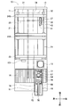
- FIG. 1 is a perspective view of an electronic component mounting machine 10 and shows a part of a housing 11 of the electronic component mounting machine 10 in a transparent state.
- FIG. 2 is a top view of the electronic component mounting machine 10.
- the electronic component mounting machine 10 is a device that mounts electronic components on the circuit boards B1 and B2 to be conveyed.
- the electronic component mounting machine 10 is provided with various devices covered with a housing 11 on a base 13 disposed on a floor surface of a manufacturing factory or the like where the electronic component mounting machine 10 is installed.
- the base 13 is formed in a substantially rectangular parallelepiped shape.
- a pair of guide rails 21 extending along the longitudinal direction of the base 13 are disposed on the base 13.
- the direction in which the pair of guide rails 21 is extended is the front-rear direction, the direction perpendicular to the front-rear direction and horizontal to the installation surface of the apparatus (the direction in which the circuit boards B1, B2 are conveyed).
- the direction perpendicular to both the left and right direction, the front and rear direction, and the left and right direction is referred to as the up and down direction.
- the substrate transfer device 20 is provided with a fixed wall 23 erected on the upper surface of a substantially central portion of the base 13.
- the fixed wall 23 has the front ends of the pair of guide rails 21 connected to both ends in the left-right direction.
- Two movable walls 24 ⁇ / b> A and 24 ⁇ / b> B are arranged on the rear side of the fixed wall 23.
- Each of the two movable walls 24 ⁇ / b> A and 24 ⁇ / b> B is attached so that both ends in the left-right direction can slide in the front-rear direction with respect to the guide rail 21.
- a lane for conveying the circuit board B1 in the left-right direction is configured.
- a lane for conveying the circuit board B2 in the left-right direction is formed between the front and rear directions of the movable walls 24A, 24B.
- the transport widths of these two lanes can be enlarged or reduced.
- the fixed wall 23 and the movable walls 24A and 24B are provided with conveyor belts for transporting the circuit boards B1 and B2 in the left-right direction at respective upper portions.
- the circuit board B1 is conveyed from the left to the right on the lane by a conveyor belt provided on each of the fixed wall 23 and the movable wall 24A.
- a backup table 26 for fixing the circuit boards B1 and B2 is provided in two lanes configured by the fixed wall 23 and the two movable walls 24A and 24B.
- Each of the backup tables 26 is provided on the base 13 below the circuit boards B1 and B2, and is configured to be movable up and down in the vertical direction.
- Each of the backup tables 26 is provided with a large number of backup pins on a rectangular plate-like upper surface, and each of the circuit boards B1 and B2 is supported and fixedly supported by the backup pins from below.
- the XY robot 31 is provided on the upper part of electronic component mounting machine 10.
- the XY robot 31 includes a Y-direction slider 32, an X-direction slider 33, a pair of left and right Y-direction guide rails 34, and a pair of upper and lower X-direction guide rails 35.
- the Y-direction slider 32, the Y-direction guide rail 34, and the X-direction guide rail 35 are indicated by alternate long and short dash lines in order to avoid making the drawing complicated.
- the X direction corresponds to the left-right direction
- the Y direction corresponds to the front-rear direction.
- Each of the pair of Y-direction guide rails 34 is disposed in a portion near the upper surface in the internal space of the housing 11 and extends in the front-rear direction.
- the Y-direction slider 32 is attached to the Y-direction guide rail 34 so as to be slidable in the front-rear direction.
- Each of the X direction guide rails 35 is disposed in front of the Y direction slider 32 and extends in the left-right direction.
- the X direction slider 33 is slidably attached to the X direction guide rail 35 in the left-right direction.
- a mark camera 37 is attached to the lower surface of the X-direction slider 33 to capture the reference marks and model numbers attached to the surface of the circuit boards B1 and B2.
- the mark camera 37 is fixed to the X-direction slider 33 while facing downward, and can be imaged at an arbitrary position on the base 13 by the XY robot 31.
- the mark camera 37 is also used for imaging the flux film F of the flux unit 18 described later in the electronic component mounting machine 10 of the present embodiment.
- the mounting head 41 is attached to the X-direction slider 33.
- the mounting head 41 is configured to be movable to an arbitrary position on the base 13 by the XY robot 31.
- the mounting head 41 is configured to be slidable in the vertical direction with respect to the X-direction slider 33.
- a parts camera 15 is provided at a position on the front side of the fixed wall 23 on the base 13. The parts camera 15 is used to take an image of the electronic component sucked by the suction nozzle 43 of the mounting head 41.
- the electronic component mounting machine 10 is provided with a device table 16 slidable in the front-rear direction on the upper surface of the front side of the base 13.
- a flux unit 18 is attached to the upper surface of the device table 16.
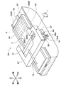
- FIG. 3 is a perspective view of the flux unit 18.
- the base 51 of the flux unit 18 is attached to the upper surface of the device table 16 (see FIGS. 1 and 2).
- the base 51 includes a rectangular bottom plate extending in the front-rear direction and a pair of side plates extending vertically upward from the left-right end of the bottom plate to form a U-shaped groove extending in the front-rear direction. Yes.
- a pair of guide rails 53 that are opposed in the left-right direction and extend along the front-rear direction are disposed on the upper surface of the bottom plate. Further, the base 51 is provided with a cable connecting portion 54 at an end on the front side on the bottom plate.
- the flux unit 18 includes a unit main body 56 that is connected to the cable connecting portion 54 and is movable in the front-rear direction along the guide rail 53.
- the unit body 56 includes a rectangular parallelepiped base 61 extending in the front-rear direction.
- the pedestal 61 is formed in a size that fits in a U-shaped groove of the base 51.
- the pedestal 61 is provided with a guided portion formed in accordance with the shape of the guide rail 53 provided on the bottom plate of the base 51, and the unit main body 56 is attached to the guide rail 53 (base 51) by an actuator (not shown). On the other hand, it is configured to be movable in the front-rear direction.
- the pedestal 61 is provided with a single guide rail 63 extending in the front-rear direction on the upper surface.
- a storage part 64 for storing flux is provided on the pedestal 61.
- the storage portion 64 is provided with a guided portion formed in accordance with the shape of the guide rail 63, and is configured to be movable in the front-rear direction with respect to the guide rail 63 (unit main body portion 56) by an actuator (not shown). Yes.
- the flux is stored in the tray of the shallow bottom where the shape seen from the top makes the rectangular shape where the longitudinal direction followed the front-back direction.
- a flux film F is formed in the tray of the storage unit 64.
- the storage unit 64 is provided with a frame 67 at the top of the tray.
- the shape of the frame 67 as viewed from above is formed in a substantially U-shaped plate opening on the rear side.
- the frame 67 is constructed from both left and right ends of the pedestal 61 so as to straddle the storage portion 64 in the left-right direction.
- the unit body 56 is provided with a syringe holding portion 68 at the front end portion.
- a cylindrical syringe 71 is fixed to the syringe holding portion 68 with a clip 72 and a belt 73. Inside the syringe 71, flux is stored.
- a cable connecting part 74 provided at the lower part is connected to the cable connecting part 54 of the base 51 by a cable 76.
- the cable 76 accommodates various power supply lines and signal lines.
- a squeegee 77 is swingably mounted in a U-shaped opening via a swing shaft 83 (see FIG. 4).
- the squeegee 77 is formed in a V-shaped plate shape (see FIG. 9) whose shape viewed from the left-right direction opens downward.
- a liquid feed tube 79 is attached to the lower surface of the syringe 71.
- One end of the liquid feeding tube 79 is connected to the syringe 71 and the other end is connected to the squeegee 77 so as to communicate the inside of the syringe 71 and the V-shaped opening of the squeegee 77.
- the flux unit 18 is configured to be able to supply flux from the syringe 71 to the storage unit 64 via the liquid feeding tube 79.
- the tips of V-shaped contact portions 77A and 77B that open downward are portions where the flux film F is scraped off.
- FIG. 4 is an enlarged perspective view of a portion of the unit main body 56 where the storage portion 64 is provided.
- the unit main body 56 includes an altitude adjusting unit 81 that adjusts the altitude of the squeegee 77.
- the altitude adjustment unit 81 includes a swing shaft 83, a swing arm 84, a rod 86, and an actuator 87.
- the swing shaft 83 is formed in a round bar shape.
- the swing shaft 83 is provided between the left and right edges of the frame 67.
- the squeegee 77 is provided with a through hole extending in the left-right direction at the bottom where two plates that are open in a V-shape are connected, and the swing shaft 83 is inserted into the through hole.
- the squeegee 77 is configured to be able to swing integrally with the swinging shaft 83 around the swinging shaft 83.
- the swing arm 84 is provided outside the right side surface of the pedestal 61 and is formed in a plate shape extending in the vertical direction. In the swing arm 84, the upper end portion of the swing arm 84 is fixed to the swing shaft 83 between the right end portion of the squeegee 77 and the inner peripheral surface of the frame 67.
- the swing arm 84 is formed with a U-shaped slit 84A that opens downward at the lower end portion.
- the rod 86 is formed in the shape of a round bar extending in the front-rear direction, and a pin 86A provided at the front end portion and protruding from the outer peripheral surface is engaged with the slit 84A.
- the rod 86 has a rod-shaped rear end that is drivingly connected to the output portion of the actuator 87.
- the rod 86 fluctuates in the front-rear direction as the actuator 87 is driven.
- the electronic component mounting machine 10 drives the actuator 87 to change the position of the rod 86 in the front-rear direction, thereby rotating the swing arm 84 and the swing shaft 83 so that the angle (tilt) of the squeegee 77 with respect to the storage portion 64 is increased. change. Thereby, the electronic component mounting machine 10 adjusts the film thickness of the flux film F formed in the storage part 64 by the altitude adjusting part 81.
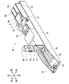
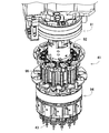
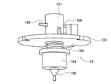
- FIG. 5 is an enlarged perspective view of the mounting head 41.
- the mounting head 41 has a substantially cylindrical rotating body 92 attached to a lower portion of a main body portion 91 fixedly held by an X-direction slider 33 (see FIGS. 1 and 2).
- the rotating body 92 is configured to be rotatable about a rotating shaft that protrudes downward and extends in the vertical direction.
- a substantially cylindrical nozzle holding unit 94 is attached below the rotating body 92.
- the nozzle holding unit 94 is configured to be detachable from the rotating body 92.
- FIG. 5 shows a state of the mounting head 41 immediately before the nozzle holding unit 94 is mounted on the main body 91, that is, immediately before the rotating body 92 is fitted into the bottomed hole.
- the nozzle holding unit 94 is configured to be able to rotate or move in the vertical direction together with the rotating body 92 by driving a drive motor (not shown) provided in the main body 91. Further, the nozzle holding unit 94 has twelve rod-shaped nozzle holders 96, and a suction nozzle 43 is attached to a sleeve 98 (see FIG. 6) provided at the lower end of each nozzle holder 96. Yes.
- the suction nozzle 43 is connected to a positive / negative pressure supply device (not shown), holds the electronic component by suction using the negative pressure, and detaches the electronic component using the positive pressure.
- the twelve nozzle holders 96 are held in an outer peripheral portion of the nozzle holding unit 94 at an equiangular pitch along the circumferential direction so that the axial direction is the vertical direction.
- Each suction nozzle 43 extends downward from the lower surface of the nozzle holding unit 94.
- Each of the nozzle holder 96 and the suction nozzle 43 is configured to be rotatable about an axis or movable in the vertical direction by a drive motor (not shown) provided in the main body 91.
- FIG. 6 is an enlarged perspective view of the suction nozzle 43 and shows a state in which the suction nozzle 43 is attached to the sleeve 98 of the nozzle holder 96.
- the suction nozzle 43 is configured to be detachable from a sleeve 98 provided at the lower end of each nozzle holder 96 of the nozzle holding unit 94.
- FIG. 7 shows the suction nozzle 43 removed from the sleeve 98.
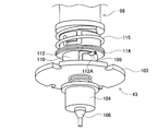
- the suction nozzle 43 includes a disk-like flange 103 provided so as to project outward from the cylindrical main cylinder 101 in the radial direction.
- the suction nozzle 43 is provided with a substantially cylindrical movable cylinder 104 below the position of the flange 103 in the main cylinder 101.
- the movable cylinder 104 is held so as to be movable back and forth in the vertical direction with respect to the main cylinder 101.
- the movable cylinder 104 is urged toward the tip (downward in FIG. 7) side of the suction nozzle 43 by a spring 106 provided between the upper surface of the movable cylinder 104 and the lower surface of the flange 103.
- the movable cylinder 104 is formed with a tip cylinder 108 formed in a tapered shape from the lower surface toward the tip, and the tip cylinder 108 functions as a nozzle.
- the suction nozzle 43 has a supply path formed in the axial direction from the base end portion toward the distal end tube 108.
- the suction nozzle 43 has a supply path connected to a positive / negative pressure supply device (not shown), and the pressure at the nozzle opening of the tip tube 108 is changed according to the atmospheric pressure in the supply path.
- the suction nozzle 43 has a pair of engaging pins 109 extending in the radial direction from the main cylinder 101.
- a cylindrical attachment portion 110 that engages with the engaging pin 109 of the suction nozzle 43 is provided at the lower end portion of the sleeve 98.
- the attachment portion 110 is formed with an inner diameter that is slightly larger than the outer diameter of the main cylinder 101 of the suction nozzle 43.
- the attachment portion 110 is formed with a pair of slots 112 (only one of which is shown in FIG. 6) for fitting the engaging pin 109 therein.
- Each slot 112 is formed with a constant circumferential width from the opening portion at the lower end of the mounting portion 110 toward the axial direction of the mounting portion 110, and is continuously attached to the upper end portion of the portion formed in the axial direction. It is formed toward one side in the circumferential direction of the portion 110 and is formed in an L shape as a whole.
- the slot 112 is formed with an engaged portion 112 ⁇ / b> A that is notched downward in accordance with the shape of the engaging pin 109 at the end of the portion formed in the circumferential direction.
- the suction nozzle 43 is mounted in a state where the engaging pin 109 is fitted in the locked portion 112 ⁇ / b> A of the slot 112.
- the mounting portion 110 has an annular retainer ring 114 that is movable in the vertical direction and is fitted on the outer peripheral surface.
- the retainer ring 114 is urged downward by a spring 115 that is provided so as to cover the outer peripheral surface of the mounting portion 110 and that can expand and contract in the axial direction.
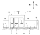
- the electronic component mounting machine 10 includes a nozzle changer 121 (see FIG. 2) in which a plurality of types of suction nozzles 43 are accommodated.
- a plurality of suction nozzles 43 are accommodated, for example, with the main cylinder 101 facing upward.
- the electronic component mounting machine 10 is configured such that each of the suction nozzles 43 mounted on the mounting head 41 and the other suction nozzles 43 accommodated in the nozzle changer 121 can be automatically replaced. More specifically, when mounting the suction nozzle 43 provided on the nozzle changer 121, the electronic component mounting machine 10 moves the mounting head 41 to the position of the nozzle changer 121.
- the electronic component mounting machine 10 controls the mounting head 41 to insert the main cylinder 101 of the suction nozzle 43 accommodated in the nozzle changer 121 into the mounting portion 110 (see FIG. 6) of an arbitrary nozzle holder 96.
- the mounting head 41 moves the nozzle holder 96 (sleeve 98) downward so that each engaging pin 109 of the suction nozzle 43 moves in the slot 112 of the mounting portion 110 along the axial direction.
- the mounting head 41 moves the sleeve 98 around the axial direction so that each engagement pin 109 moves in the circumferential direction in the slot 112 in a state where the main cylinder 101 is inserted into the mounting portion 110. Rotate.
- the mounting head 41 rotates the sleeve 98 until the engaging pin 109 reaches the position of the locked portion 112A of the slot 112, and raises the position of the sleeve 98.
- the retainer ring 114 presses the engaging pin 109 downward by the urging force of the spring 115, so that the suction nozzle 43 is fixed to the sleeve 98 in a state where the engaging pin 109 is fitted in the locked portion 112A. Is done.
- the operation of removing the suction nozzle 43 from the sleeve 98 by the mounting head 41 can be performed by performing the reverse operation to the case where the suction nozzle 43 is mounted, and thus detailed description thereof is omitted here.
- the film thickness gauge 131 of the present embodiment is configured in a nozzle shape that can be replaced with the suction nozzle 43.
- the same components as those of the suction nozzle 43 shown in FIG. 7 are denoted by the same reference numerals, and the description thereof is omitted as appropriate.
- the film thickness gauge 131 includes a gauge portion 133 that is biased toward the distal end side by a spring 106 at the distal end of the main cylinder 101.
- the gauge part 133 includes a circular disk part 134 whose main surface is perpendicular to the axial direction of the main cylinder 101.
- the disc portion 134 has a circular center on the axis of the rotation axis of the main cylinder 101, and a pair of positioning portions 135 formed toward the tip end side along the axial direction is formed on the outer peripheral portion.
- the positioning portion 135 is formed in a plate shape extending in the axial direction, and a cross-sectional shape formed along the outer periphery of the disc portion 134 and cut along a plane orthogonal to the axial direction forms an arc shape.
- Each of the positioning portions 135 is provided at a position facing each other in the radial direction of the disc portion 134 and has the same axial length.
- the disk part 134 has a plurality of (four in the illustrated example) measuring parts 136 formed in the central part.
- Each of the measurement parts 136 has a rectangular parallelepiped shape formed along the axial direction from the base end part connected to the disk part 134 to the distal end side.
- Each of the measuring units 136 is arranged in a quadrangular shape so as to surround the center of the disk unit 134.
- Each measuring unit 136 has a shorter axial length than the positioning unit 135.
- each of the measurement units 136 has a different axial length.
- the film thickness gauge 131 is attached to the sleeve 98 of the suction nozzle 43, and the film thickness gauge 131 is immersed in the storage section 64 of the flux unit 18 and is formed on the flux film F by each of the measurement sections 136.
- the film thickness is measured by detecting traces.
- each of the measuring units 136 is set to have an axial length corresponding to the film thickness to be measured.
- the measurement unit 136 illustrated in FIG. 8 is illustrated in a size different from the actual size. Further, the shape, arrangement, number, and the like of the measurement unit 136 shown in FIG. 8 are examples. In the following description, in order to distinguish the four measurement units 136, the measurement units 136A, 136B, 136C, and 136D will be described in order from the longest axial length.
- the film thickness gauge 131 is accommodated together with the suction nozzle 43 in the nozzle changer 121 shown in FIG.
- the electronic component mounting machine 10 drives the nozzle holding unit 94 so as to replace the suction nozzle 43 of any nozzle holder 96 with the film thickness gauge 131 according to the timing at which the film thickness of the flux film F is measured. For example, each time the electronic component mounting machine 10 changes the type of circuit boards B1, B2 (see FIG. 1) to be produced or the type of electronic components to be supplied, the film of the flux film F of the flux unit 18 accordingly. In order to adjust the thickness, the suction nozzle 43 and the film thickness gauge 131 are exchanged.
- FIG. 9 is a cross-sectional view of the flux unit 18.
- the unit main body 56 is disposed on the rear side of the base 51 during the production of the circuit boards B1 and B2.
- the electronic component mounting machine 10 drives the squeegee 77 of the flux unit 18 to form the flux film F having a desired film thickness in the storage portion 64.
- the electronic component mounting machine 10 moves the reservoir 64 to the rear side with respect to the squeegee 77 by an actuator (not shown).
- the squeegee 77 is disposed near the front end with respect to the storage portion 64.
- the electronic component mounting machine 10 changes the inclination of the squeegee 77 to a desired angle by driving the altitude adjusting unit 81 (see FIG. 4) of the unit main body 56.
- the front contact portion 77A is on the lower side compared to the rear contact portion 77B.
- the film thickness of the formed flux film is changed by the amount by which the contact portion 77A is inclined downward.
- the depth at which the tip of the inclined contact portion 77A is immersed in the formed flux film F corresponds to the amount of adjustment (scraping) of the film thickness.
- the electronic component mounting machine 10 supplies the flux into the squeegee 77 from the syringe 71 via the liquid feeding tube 79.
- the electronic component mounting machine 10 moves the storage unit 64 to the front side with respect to the squeegee 77.
- the flux film F is formed by the contact portion 77A.
- the electronic component mounting machine 10 drives the altitude adjusting unit 81 to change the inclination of the squeegee 77, and the rear contact part 77B is inclined downward relative to the front contact part 77A.
- the contact portion 77 ⁇ / b> B forms the flux film F by moving the storage portion 64 rearward with respect to the squeegee 77. By repeating this operation, a flux film F having a desired film thickness is formed.
- the electronic component mounting machine 10 measures the film thickness of the flux film F formed in the storage unit 64 with the film thickness gauge 131.
- the electronic component mounting machine 10 moves the mounting head 41 mounted with the film thickness gauge 131 to the position of the storage unit 64.
- the mounting head 41 lowers the film thickness gauge 131 and immerses the positioning part 135 (see FIG. 8) and the measurement parts 136A to 136D in the formed flux film F.
- the position where the film thickness gauge 131 is lowered is set to coincide with the position where the electronic components mounted on the circuit boards B1 and B2 to be produced are immersed. For example, as illustrated in FIG.
- an immersion region R in which an electrode of an electronic component held by the suction nozzle 43 is immersed is set in the flux film F formed in the storage unit 64.
- the range of the immersion region R is appropriately changed according to the type of electronic component.
- the mounting head 41 executes control for immersing the film thickness gauge 131 in the immersion region R.
- FIG. 10 is a schematic view of a state in which the film thickness gauge 131 is immersed in the flux film F.
- FIG. 10 illustrates only two measurement units 136A and 136B among the four measurement units 136A to 136D.
- the mounting head 41 lowers the film thickness gauge 131 until the distal end surface of the positioning part 135 comes into contact with the bottom part 64 ⁇ / b> A of the storage part 64.
- Each of the measuring units 136A and 136B has an axial length corresponding to the film thickness to be measured.
- the film thickness of the formed flux film F is defined as film thickness T.
- the film thickness T is changed according to the type of electronic component mounted on the circuit boards B1 and B2 and the shape of the electrode. Further, in FIG.
- the measurement unit 136A on the front side has a length in the axial direction shorter than the positioning unit 135 by the length L1. Further, the measuring unit 136B is shorter in length in the axial direction than the positioning unit 135 by the length L2.
- the film thickness T is, for example, 160 ⁇ m.
- the length L1 is, for example, 150 ⁇ m.
- the length L2 is, for example, 175 ⁇ m.
- the measurement unit 136A having the length L1 is immersed, and the measurement unit 136B having the length L2 is not immersed. Therefore, a measurement mark 200A is formed on the surface of the flux film F by being recessed by the measurement unit 136A.
- the electronic component mounting machine 10 images the measurement mark 200A by the mark camera 37 attached to the X-direction slider 33 (see FIG. 2), and detects the film thickness T of the flux film F based on the imaging data. Therefore, in each of the measurement units 136A to 136D, a length (length L1, L2, etc.) that shortens the axial length as compared with the positioning unit 135 is set according to the film thickness T to be measured. .
- measurement marks 200A to 200D formed by the four measurement parts 136A to 136D shown in FIG. 8 are formed according to the film thickness T of the flux film F.
- the electronic component mounting machine 10 detects the measurement marks 200A to 200D based on the imaging data obtained by the mark camera 37 imaging the immersion area R. In the above example, since the measurement marks 200B to 200D are not formed, but only the measurement marks 200A are formed, the electronic component mounting machine 10 determines that the film thickness T of the immersion region R is between 150 ⁇ m and 175 ⁇ m. To do.
- the electronic component mounting machine 10 automatically adjusts the angle of the squeegee 77 to thin or thicken the flux film F. Do.
- the electronic component mounting machine 10 drives the altitude adjusting unit 81 to adjust the inclination of the squeegee 77 to an angle at which the contact portions 77A and 77B are more immersed in the flux film F, and then stores the adjusted squeegee 77 in the storage unit 64. , The excess of the flux film F is scraped off to reduce the thickness.
- the electronic component mounting machine 10 measures the film thickness T again after adjusting the film thickness T.
- the electronic component mounting machine 10 If the detected film thickness T of the immersion region R matches the film thickness according to the electronic component to be mounted, the electronic component mounting machine 10 eliminates the measurement marks 200A to 200D formed for measurement. Then, after the process of forming the flux film F again without changing the angle of the squeegee 77, the mounting operation of the electronic component is started.
- the electronic component mounting machine 10 immerses the electrode of the electronic component sucked and held by the suction nozzle 43 (see FIG. 6) in the immersion region R of the flux film F of the storage unit 64 by driving the mounting head 41. An amount of flux corresponding to the film thickness of the flux film F adheres to the electrode of the electronic component.
- the electronic component mounting machine 10 passes the electronic component after the flux is adhered to above the parts camera 15 (see FIGS.
- the electronic component mounting machine 10 performs adjustment based on the orientation error of the electronic component imaged by the parts camera 15 and mounts the electronic component on the circuit board B1 or the circuit board B2. In this way, the electronic component mounting machine 10 performs the mounting operation while adjusting the film thickness T of the flux film F in accordance with the type of electronic component to be supplied.
- the electronic component mounting machine 10 of this embodiment includes a flux unit 18 that transfers the flux to the electrodes of the electronic component.
- the flux unit 18 spreads the flux stored in the storage portion 64 with a squeegee 77 and forms a flux film F.
- the electronic component mounting machine 10 includes a film thickness gauge 131 for measuring the film thickness T of the flux film F.
- the film thickness gauge 131 is configured to be mountable to the mounting head 41 that holds an electronic component.
- the film thickness gauge 131 is provided with measuring portions 136A to 136D formed with an axial length corresponding to the measured value of the film thickness T.
- the mounting head 41 moves to a position above the storage portion 64 and lowers the mounted film thickness gauge 131 to contact the surface of the flux film F.
- the film thickness gauge 131 measurement marks 200A to 200D corresponding to the film thickness T are formed on the flux film F by the measuring units 136A to 136D, respectively.
- the electronic component mounting machine 10 images the measurement marks 200A to 200D formed on the flux film F with the mark camera 37, and executes the detection process of the measurement marks 200A to 200D based on the image data.
- the electronic component mounting machine 10 determines the film thickness T of the flux film F actually formed from the detected measurement marks 200A to 200D.
- the electronic component mounting machine 10 can automatically manage the film thickness T in accordance with the type of electronic component to be supplied, and work efficiency is improved.
- the operator of the electronic component mounting machine 10 manually measures the film thickness T
- the operator forgets the measurement work at a necessary timing, or the film thickness held by the operator.
- an artificial error such that the thickness of the gauge cannot be measured due to the position of the gauge being shifted.
- the operator manually measures the film thickness T for example, it is necessary to stop the production line and pull the flux unit 18 along the device table 16 before measuring the circuit boards B1 and B2. Production efficiency decreases.
- the electronic component mounting machine 10 of the present embodiment since a human error is eliminated and the film thickness is automatically adjusted in a series of production steps, production efficiency is improved.
- the film thickness T can be measured without using a sensor or the like by the configuration in which the film thickness gauge 131 is held by the mounting head 41 and measured, and the structure of the apparatus is simplified. And the size of the apparatus can be reduced, and the manufacturing cost of the apparatus can be reduced.
- the flux unit 18 includes a V-shaped squeegee 77 that contacts the surface of the flux stored in the storage section 64 to form a flux film F having a desired film thickness T.
- the electronic component mounting machine 10 changes the inclination of the squeegee 77 by driving the altitude adjusting unit 81 of the flux unit 18 in accordance with the detected film thickness T, so that the contact portion 77A of the squeegee 77 with respect to the bottom 64A of the storage unit 64 is obtained.
- 77B is changed in relative height. When the height of the contact portions 77A and 77B is high, the film thickness T of the formed flux film F is thick.
- the electronic component mounting machine 10 can form the flux film F having a desired film thickness T by adjusting the altitudes of the contact portions 77A and 77B in accordance with the detected film thickness T. .
- ⁇ Effect 3> The position where the film thickness gauge 131 is brought into contact with the flux film F is set in the immersion region R in which the electronic component held by the mounting head 41 is immersed in the flux film F. That is, the position where the film thickness T is measured is the position where the electronic component is actually immersed. For this reason, in the electronic component mounting machine 10 according to the present embodiment, the amount of flux transferred to the electrodes of the electronic component can be more appropriately managed, and the number of defective substrates flowing in the subsequent process can be reduced. Improvement can be achieved.
- the film thickness gauge 131 is held by the mounting head 41.
- the mounting head 41 brings the film thickness gauge 131 into contact with the flux film F by driving the nozzle holding unit 94 and the nozzle holder 96.
- the electronic component mounting machine 10 it is not necessary to separately provide a dedicated moving device for holding and moving the film thickness gauge 131, and the film thickness T can be appropriately managed while simplifying the structure of the device. It becomes possible.
- the film thickness gauge 131 has a nozzle shape that can be replaced with the suction nozzle 43 with respect to the nozzle holder 96 (sleeve 98) of the mounting head 41 (see FIG. 8).
- the electronic component mounting machine 10 drives the mounting head 41 so that the suction nozzle 43 and the film thickness gauge 131 are exchanged according to the timing at which the film thickness of the flux film F is measured.
- the electronic component mounting machine 10 can automatically measure the film thickness T at an appropriate timing such as a timing at which the type of electronic component to be supplied is replaced.
- the film thickness gauge 131 is such that when the mounting head 41 lowers the nozzle holder 96 when measuring the flux film F, the tip surface of the positioning portion 135 comes into contact with the bottom 64A of the storage portion 64.
- the position of 131 is determined (see FIG. 10).
- the film thickness gauge 131 is formed with measuring portions 136A to 136D having different lengths along the axial direction. Each of the measurement units 136A to 136D is at a position where the relative heights with respect to the bottom 64A are different from each other when the positioning unit 135 is in contact with the bottom 64A of the storage unit 64. According to the film thickness gauge 131, since the measurement position is stably determined by contacting the positioning portion 135, the measurement marks 200A to 200D corresponding to the film thickness T can be accurately formed on the flux film F. It becomes.
- the mark camera 37 for imaging the reference marks and model numbers attached to the surfaces of the circuit boards B1 and B2 is used to image the measurement marks 200A to 200D. It is not necessary to provide a dedicated camera or the like.
- the mark camera 37 is an example of an imaging unit.
- the mounting head 41 including the suction nozzle 43 is an example of a movable part.
- the suction nozzle 43 is an example of a mounting nozzle.
- a flux is an example of a viscous fluid.
- the flux film F is an example of a fluid film.
- the film thickness gauge 131 can be mounted on the mounting head 41.
- the film thickness gauge 131 is held and moved by a moving device provided separately from the mounting head 41 and the XY robot 31. You may change to
- the film thickness gauge 131 was comprised in the nozzle shape replaceable with the suction nozzle 43, it is not limited to this.
- the film thickness gauge 131 may be formed in a plate shape, and a plurality of measurement units 136A to 136D may be formed in a comb shape.
- the mounting head 41 is good also as a structure which pinches
- the plate-shaped film thickness gauge 131 used in this case may be a film thickness gauge for measuring an existing film thickness that is generally used.
- the mounting head 41 may be configured to attract or detach the film thickness gauge 131 by electromagnetic force.
- the measurement unit 136 (measurement units 136A to 136D) has a rectangular parallelepiped shape, but the shape is not particularly limited.
- the shape of the measuring unit 136 may be a prismatic shape other than a rectangular parallelepiped, or may be a cylindrical shape.
- cleaning of the measuring unit 136 using a brush or the like cleaning is easier when the measuring unit 136 has a prismatic shape than a columnar shape.
- the arrangement, the number, and the like of the measurement units 136 provided in the film thickness gauge 131 are examples and are not particularly limited.
- the electronic component mounting machine 10 may include a plurality of types of film thickness gauges 131.
- the shape of the measurement part 136 with which each film thickness gauge 131 is provided may differ from each other.
- one film thickness gauge 131 may include measurement units 136 having different shapes.
- the film thickness gauge 131 is configured to be detachable from the suction nozzle 43, but the film thickness gauge 131 may be fixedly provided to the suction nozzle 43.
- FIG. 11 shows a top view of another example of the flux unit 18A.
- a flux unit 18 ⁇ / b> A shown in FIG. 11 includes a circular reservoir 64.
- the storage unit 64 is arranged on the rotary table and is configured to be rotatable in the direction of the arrow in the drawing.
- the flux in the syringe 71 is supplied from the discharge nozzle 141 and the flux is stored.
- a plate-like squeegee 77 having a length substantially the same as the radius of the storage portion 64 is disposed above the storage portion 64 along the radial direction.
- the flux unit 18 ⁇ / b> A drives the rotary table to rotate the storage portion 64, thereby spreading the flux in the storage portion 64 by the linear contact portion 77 ⁇ / b> C of the squeegee 77 to form the flux film F.
- the flux unit 18A is provided with an altitude adjusting unit 81 that adjusts the height of the squeegee 77 (position in the direction perpendicular to the paper surface in FIG. 11).
- the altitude adjusting unit 81 adjusts the height of the squeegee 77 to
- the film thickness of the flux film F is changed by adjusting the gap between the reservoir 64 and the bottom.
- the film thickness of the flux film F is appropriately managed by setting the immersion region R in which the electronic component is immersed and measuring with the film thickness gauge 131 as in the above embodiment. It becomes possible.
- the electronic component mounting machine 10 was set as the structure which adjusts the film thickness T automatically according to a measurement result, as a structure which an operator notifies a measurement result and an operator adjusts manually. Also good.
- the flux unit 18A shown in FIG. 11 is provided with an operation panel 143 for sliding the unit main body 56 on the device table 16 (see FIG. 1) for manual operation. In the state where the unit main body portion 56 is pulled out to the pulling position, the flux unit 18A has a storage portion 64 for adjusting the film thickness of the flux film F if the operator operates the operation panel 143 and performs manual operation. Can be rotated to form a flux film F, or flux can be replenished from the syringe 71 to the reservoir 64.
- the flux unit 18 may have a configuration in which a plurality of flux films F having different film thicknesses are formed in one reservoir 64. Further, the immersion region R may be set at a plurality of positions. Further, the measurement with the film thickness gauge 131 may be performed at a plurality of locations in one measurement, and for example, an average value or the like may be calculated as a measurement result.
- the viscous fluid in the present application is not limited to flux, and may be other viscous fluid (for example, cream solder).
- the electronic component mounting machine 10 is configured to also use the mark camera 37 used for other purposes as an imaging unit for imaging the measurement marks 200A to 200D.
- a dedicated camera for imaging 200D may be provided.
- the dedicated camera may be provided in the flux unit 18.
- the mounting head 41 includes the suction nozzle 43 that sucks and holds the electronic component by a change in atmospheric pressure as the mounting nozzle that holds the electronic component.
- the mounting head 41 is configured to hold the electronic component by another method.
- a nozzle may be provided.
Landscapes
- Engineering & Computer Science (AREA)
- Manufacturing & Machinery (AREA)
- Microelectronics & Electronic Packaging (AREA)
- Operations Research (AREA)
- Electric Connection Of Electric Components To Printed Circuits (AREA)
- Supply And Installment Of Electrical Components (AREA)
Abstract
Description
次に、図4に示すフラックスユニット18の貯留部64に形成されたフラックス膜Fの膜厚を測定するための膜厚ゲージ131について図8を用いて説明する。図8に示すように、本実施形態の膜厚ゲージ131は、吸着ノズル43と交換可能なノズル形状に構成されている。なお、以下の説明では、図7に示す吸着ノズル43と同様の構成については同一の符号を付し、その説明を適宜省略する。膜厚ゲージ131は、主筒101の先端にスプリング106によって先端側に付勢されるゲージ部133を備える。ゲージ部133は、主面が主筒101の軸方向に対して垂直となる円形の円板部134を備える。円板部134は、円形の中心が主筒101の回転軸の軸線上となっており、外周部分に軸方向に沿って先端側に向かって形成された一対の位置決め部135が形成されている。位置決め部135は、軸方向に延びる板状に形成され、円板部134の外周に沿って形成され軸方向に直交する平面で切断した断面形状が円弧状をなしている。位置決め部135の各々は、円板部134の径方向において互いに対向する位置に設けられており、軸方向の長さが同一となっている。
次に、電子部品実装機10は、貯留部64に形成されたフラックス膜Fの膜厚を膜厚ゲージ131によって測定する。電子部品実装機10は、膜厚ゲージ131を装着した装着ヘッド41を貯留部64の位置まで移動させる。装着ヘッド41は、膜厚ゲージ131を下降させ位置決め部135(図8参照)及び測定部136A~136Dを形成されたフラックス膜Fに浸漬させる。この膜厚ゲージ131を下降させる位置は、生産する回路基板B1,B2に実装する電子部品を浸漬させる位置と一致するように設定する。例えば、図4に示すように、貯留部64に形成されたフラックス膜Fには、吸着ノズル43に保持された電子部品の電極を浸漬させる浸漬領域Rが設定されている。この浸漬領域Rは、電子部品の種類などに応じて範囲が適宜変更される。装着ヘッド41は、膜厚ゲージ131をこの浸漬領域R内に浸漬させる制御を実行する。
<効果1>本実施形態の電子部品実装機10は、フラックスを電子部品の電極に転写するフラックスユニット18を備える。フラックスユニット18は、貯留部64に貯留されたフラックスをスキージ77によって押し広げフラックス膜Fを形成する。また、電子部品実装機10は、フラックス膜Fの膜厚Tを測定するための膜厚ゲージ131を備える。膜厚ゲージ131は、電子部品を保持する装着ヘッド41に対して装着可能に構成されている。膜厚ゲージ131は、膜厚Tの測定値に応じた軸方向の長さで形成された測定部136A~136Dが設けられている。装着ヘッド41は、貯留部64の上方の位置まで移動し装着した膜厚ゲージ131を下降させフラックス膜Fの表面に接触させる。膜厚ゲージ131は、測定部136A~136Dの各々によって、膜厚Tに応じた測定痕200A~200Dをフラックス膜Fに形成する。電子部品実装機10は、フラックス膜Fに形成した測定痕200A~200Dをマークカメラ37によって撮像し、撮像データに基づいて測定痕200A~200Dの検出処理を実行する。電子部品実装機10は、検出した測定痕200A~200Dから実際に形成されたフラックス膜Fの膜厚Tを判定する。
例えば、上記実施形態では、膜厚ゲージ131を装着ヘッド41に装着可能な構成としたが、例えば装着ヘッド41やXYロボット31とは別に設けた移動装置によって膜厚ゲージ131を保持及び移動させる構成に変更してもよい。
また、上記実施形態では、膜厚ゲージ131を、吸着ノズル43と交換可能なノズル形状に構成したが、これに限定されない。例えば、膜厚ゲージ131は、板状に形成され、複数の測定部136A~136Dが櫛歯状に形成された構成でもよい。そして、装着ヘッド41は、板状の膜厚ゲージ131を機械的に挟む構成としてもよい。この場合に用いる板状の膜厚ゲージ131は、一般に用いられる既存の膜厚を測定するための膜厚ゲージでもよい。あるいは、装着ヘッド41は、膜厚ゲージ131を電磁力によって吸着又は離脱する構成でもよい。
また、膜厚ゲージ131に設けた測定部136の配置、個数等は、一例であり特に限定されない。
また、電子部品実装機10は、複数の種類の膜厚ゲージ131を備えてもよい。この場合、各膜厚ゲージ131が備える測定部136の形状は互いに異なっていてもよい。また、1つの膜厚ゲージ131が、互いに異なる形状の測定部136を備えてもよい。
また、上記実施形態では、膜厚ゲージ131を、吸着ノズル43に対して着脱可能に構成したが、膜厚ゲージ131を吸着ノズル43に対して固定的に設けてもよい。
また、浸漬領域Rは、複数の位置に設定してもよい。
また、膜厚ゲージ131による測定は、1回の測定で複数箇所実施し、例えば、その平均値等を算出し測定結果としてもよい。
また、上記実施形態では、電子部品実装機10は、測定痕200A~200Dを撮像するための撮像部として、他の用途にも用いるマークカメラ37を兼用する構成であったが、測定痕200A~200Dを撮像するための専用のカメラを備えてもよい。この場合、専用のカメラは、フラックスユニット18が備えてもよい。
また、上記実施形態では、装着ヘッド41は、電子部品を保持する装着ノズルとして気圧の変化によって電子部品を吸着保持する吸着ノズル43を備えたが、他の方法で電子部品を保持する構成の装着ノズルを備えてもよい。
Claims (6)
- 粘性流体が貯留され前記粘性流体の流体膜が形成される貯留部と、
電子部品を保持して移動し、前記電子部品を前記流体膜に浸漬させる可動部と、
前記流体膜に接触させることによって前記流体膜の膜厚を測定するための測定値に応じた測定痕を前記流体膜に形成する膜厚ゲージと、
前記膜厚ゲージによって前記流体膜に形成された前記測定痕を撮像する撮像部と、を備え、
前記撮像部の撮像データに基づいて前記流体膜の膜厚を検出することを特徴とする電子部品実装機。 - 前記粘性流体に接触し、前記貯留部に対する相対的な高さに応じた膜厚の前記流体膜を形成するスキージと、
検出された前記流体膜の膜厚に応じて、前記貯留部に対する前記スキージの相対的な高さを変更し前記膜厚を調整する高度調整部と、
を備えることを特徴とする請求項1に記載の電子部品実装機。 - 前記膜厚ゲージを前記流体膜に接触させる位置が、前記可動部により保持された前記電子部品を前記流体膜に浸漬される浸漬領域となるように設定されることを特徴とする請求項1又は請求項2に記載の電子部品実装機。
- 前記膜厚ゲージは、前記可動部により保持されるものであり、前記可動部の移動に応じて前記流体膜に接触することを特徴とする請求項1乃至請求項3のいずれかに記載の電子部品実装機。
- 前記可動部は、前記電子部品を保持する装着ノズルが着脱可能に構成され、
前記膜厚ゲージは、前記可動部に対して前記装着ノズルと交換可能に構成され、
前記流体膜の膜厚を測定するタイミングに応じて前記装着ノズルと前記膜厚ゲージとを交換させるように前記可動部を駆動することを特徴とする請求項4に記載の電子部品実装機。 - 前記膜厚ゲージは、
前記流体膜に接触する際に前記貯留部の底部に当接し当該膜厚ゲージの位置を決定する位置決め部と、
前記位置決め部が前記貯留部の底部に当接された状態において、前記底部に対する相対的な高さが互いに異なった位置となり前記膜厚に応じた前記測定痕を前記流体膜に形成する複数の測定部と、を備えることを特徴とする請求項1乃至請求項5のいずれかに記載の電子部品実装機。
Priority Applications (5)
| Application Number | Priority Date | Filing Date | Title |
|---|---|---|---|
| US15/102,941 US9961818B2 (en) | 2013-12-23 | 2013-12-23 | Electronic component mounting machine including a film thickness gauge |
| CN201380081771.1A CN105830552B (zh) | 2013-12-23 | 2013-12-23 | 电子元件安装机 |
| JP2015554314A JP6280931B2 (ja) | 2013-12-23 | 2013-12-23 | 電子部品実装機 |
| PCT/JP2013/084387 WO2015097731A1 (ja) | 2013-12-23 | 2013-12-23 | 電子部品実装機 |
| EP13900566.4A EP3089573B1 (en) | 2013-12-23 | 2013-12-23 | Electronic component mounting machine |
Applications Claiming Priority (1)
| Application Number | Priority Date | Filing Date | Title |
|---|---|---|---|
| PCT/JP2013/084387 WO2015097731A1 (ja) | 2013-12-23 | 2013-12-23 | 電子部品実装機 |
Publications (1)
| Publication Number | Publication Date |
|---|---|
| WO2015097731A1 true WO2015097731A1 (ja) | 2015-07-02 |
Family
ID=53477675
Family Applications (1)
| Application Number | Title | Priority Date | Filing Date |
|---|---|---|---|
| PCT/JP2013/084387 WO2015097731A1 (ja) | 2013-12-23 | 2013-12-23 | 電子部品実装機 |
Country Status (5)
| Country | Link |
|---|---|
| US (1) | US9961818B2 (ja) |
| EP (1) | EP3089573B1 (ja) |
| JP (1) | JP6280931B2 (ja) |
| CN (1) | CN105830552B (ja) |
| WO (1) | WO2015097731A1 (ja) |
Cited By (2)
| Publication number | Priority date | Publication date | Assignee | Title |
|---|---|---|---|---|
| WO2022137457A1 (ja) * | 2020-12-24 | 2022-06-30 | 株式会社Fuji | 基板作業機及び粘性体の深さの測定方法 |
| US11425851B2 (en) * | 2017-03-31 | 2022-08-23 | Fuji Corporation | Electronic component mounting machine and mounting method |
Families Citing this family (7)
| Publication number | Priority date | Publication date | Assignee | Title |
|---|---|---|---|---|
| CN108293321B (zh) * | 2015-11-25 | 2019-12-03 | 株式会社富士 | 工具检索装置 |
| JP6796363B2 (ja) * | 2016-10-05 | 2020-12-09 | 株式会社Fuji | 部品実装機 |
| DE102017131322B4 (de) * | 2017-12-27 | 2019-07-04 | Asm Assembly Systems Gmbh & Co. Kg | Verwenden von bestückfähigen Markierungsbausteinen für ein stufenweises Bestücken eines Trägers mit Bauelementen |
| US11446750B2 (en) | 2020-02-03 | 2022-09-20 | Io Tech Group Ltd. | Systems for printing solder paste and other viscous materials at high resolution |
| US11622451B2 (en) | 2020-02-26 | 2023-04-04 | Io Tech Group Ltd. | Systems and methods for solder paste printing on components |
| US11497124B2 (en) | 2020-06-09 | 2022-11-08 | Io Tech Group Ltd. | Methods for printing conformal materials on component edges at high resolution |
| US11691332B2 (en) | 2020-08-05 | 2023-07-04 | Io Tech Group Ltd. | Systems and methods for 3D printing with vacuum assisted laser printing machine |
Citations (7)
| Publication number | Priority date | Publication date | Assignee | Title |
|---|---|---|---|---|
| JP2003142814A (ja) * | 2001-11-07 | 2003-05-16 | Matsushita Electric Ind Co Ltd | 電子部品実装装置および電子部品実装方法ならびにペースト供給装置 |
| JP2004288796A (ja) * | 2003-03-20 | 2004-10-14 | Matsushita Electric Ind Co Ltd | 部品実装装置及び部品実装方法 |
| JP2008010525A (ja) * | 2006-06-28 | 2008-01-17 | Fuji Mach Mfg Co Ltd | フラックス転写装置 |
| JP2008130985A (ja) | 2006-11-24 | 2008-06-05 | Juki Corp | 電子部品実装装置におけるフラックス供給・回収装置 |
| JP2009016650A (ja) * | 2007-07-06 | 2009-01-22 | Elpida Memory Inc | フラックス転写装置及び電子部品搭載方法 |
| JP2010165702A (ja) * | 2009-01-13 | 2010-07-29 | Panasonic Corp | 電子部品実装装置及び電子部品実装方法 |
| JP2013074004A (ja) * | 2011-09-27 | 2013-04-22 | Panasonic Corp | 電子部品実装装置および電子部品実装装置におけるペースト転写方法 |
Family Cites Families (19)
| Publication number | Priority date | Publication date | Assignee | Title |
|---|---|---|---|---|
| US1909652A (en) * | 1931-06-01 | 1933-05-16 | Nat Tile Company | Glazing thickness gauge |
| US4169319A (en) * | 1978-09-06 | 1979-10-02 | Paul N. Gardner Company | Methods and apparatus for measuring the thickness of wet films |
| US4345371A (en) * | 1979-03-14 | 1982-08-24 | Sony Corporation | Method and apparatus for manufacturing hybrid integrated circuits |
| US4869418A (en) * | 1986-06-11 | 1989-09-26 | International Business Machines Corporation | Solder leveling method and apparatus |
| US5040291A (en) * | 1990-05-04 | 1991-08-20 | Universal Instruments Corporation | Multi-spindle pick and place method and apparatus |
| JP2601075B2 (ja) * | 1991-10-21 | 1997-04-16 | 株式会社日立製作所 | 試験片を用いる分析方法および分析装置 |
| JPH1034456A (ja) * | 1996-07-24 | 1998-02-10 | Fuji Mach Mfg Co Ltd | 電子部品供給装置 |
| JP4494547B2 (ja) * | 1999-03-10 | 2010-06-30 | Juki株式会社 | 電子部品検出装置 |
| JP4187873B2 (ja) * | 1999-05-27 | 2008-11-26 | 日立ビアメカニクス株式会社 | 導電性ボール搭載装置におけるフラックス供給装置 |
| US6546797B2 (en) * | 2000-08-24 | 2003-04-15 | Mlho, Inc. | Absolute position measure with multi-beam optical encoding |
| US6672156B1 (en) * | 2001-08-08 | 2004-01-06 | Mlno, Inc. | Absolute liquid level sensor with refractive encoding |
| US20030077396A1 (en) * | 2001-10-23 | 2003-04-24 | Lecompte Robert S. | Dip coating system |
| JP2005150340A (ja) * | 2003-11-14 | 2005-06-09 | Hitachi Ltd | エッチング条件だし方法およびその装置 |
| US20070084283A1 (en) * | 2005-10-18 | 2007-04-19 | Bj Services Company | Safety tank level gauging system |
| JP4816194B2 (ja) * | 2006-03-29 | 2011-11-16 | パナソニック株式会社 | 電子部品実装システムおよび電子部品搭載装置ならびに電子部品実装方法 |
| EP1921427B1 (en) * | 2006-11-07 | 2019-02-27 | LG Electronics Inc. | Automatic liquid dispensers with liquid level detector |
| JP5610915B2 (ja) * | 2010-08-17 | 2014-10-22 | 富士機械製造株式会社 | ディップフラックスユニット |
| KR102034820B1 (ko) * | 2012-11-30 | 2019-11-08 | 삼성전자주식회사 | 반도체 칩 실장장치 및 이를 이용한 반도체 칩의 실장방법 |
| US8944001B2 (en) * | 2013-02-18 | 2015-02-03 | Nordson Corporation | Automated position locator for a height sensor in a dispensing system |
-
2013
- 2013-12-23 EP EP13900566.4A patent/EP3089573B1/en active Active
- 2013-12-23 US US15/102,941 patent/US9961818B2/en active Active
- 2013-12-23 CN CN201380081771.1A patent/CN105830552B/zh active Active
- 2013-12-23 WO PCT/JP2013/084387 patent/WO2015097731A1/ja active Application Filing
- 2013-12-23 JP JP2015554314A patent/JP6280931B2/ja active Active
Patent Citations (7)
| Publication number | Priority date | Publication date | Assignee | Title |
|---|---|---|---|---|
| JP2003142814A (ja) * | 2001-11-07 | 2003-05-16 | Matsushita Electric Ind Co Ltd | 電子部品実装装置および電子部品実装方法ならびにペースト供給装置 |
| JP2004288796A (ja) * | 2003-03-20 | 2004-10-14 | Matsushita Electric Ind Co Ltd | 部品実装装置及び部品実装方法 |
| JP2008010525A (ja) * | 2006-06-28 | 2008-01-17 | Fuji Mach Mfg Co Ltd | フラックス転写装置 |
| JP2008130985A (ja) | 2006-11-24 | 2008-06-05 | Juki Corp | 電子部品実装装置におけるフラックス供給・回収装置 |
| JP2009016650A (ja) * | 2007-07-06 | 2009-01-22 | Elpida Memory Inc | フラックス転写装置及び電子部品搭載方法 |
| JP2010165702A (ja) * | 2009-01-13 | 2010-07-29 | Panasonic Corp | 電子部品実装装置及び電子部品実装方法 |
| JP2013074004A (ja) * | 2011-09-27 | 2013-04-22 | Panasonic Corp | 電子部品実装装置および電子部品実装装置におけるペースト転写方法 |
Cited By (2)
| Publication number | Priority date | Publication date | Assignee | Title |
|---|---|---|---|---|
| US11425851B2 (en) * | 2017-03-31 | 2022-08-23 | Fuji Corporation | Electronic component mounting machine and mounting method |
| WO2022137457A1 (ja) * | 2020-12-24 | 2022-06-30 | 株式会社Fuji | 基板作業機及び粘性体の深さの測定方法 |
Also Published As
| Publication number | Publication date |
|---|---|
| JP6280931B2 (ja) | 2018-02-14 |
| EP3089573A4 (en) | 2016-12-07 |
| US20160330882A1 (en) | 2016-11-10 |
| EP3089573A1 (en) | 2016-11-02 |
| EP3089573B1 (en) | 2018-03-07 |
| CN105830552B (zh) | 2019-01-18 |
| US9961818B2 (en) | 2018-05-01 |
| CN105830552A (zh) | 2016-08-03 |
| JPWO2015097731A1 (ja) | 2017-03-23 |
Similar Documents
| Publication | Publication Date | Title |
|---|---|---|
| JP6280931B2 (ja) | 電子部品実装機 | |
| US20160302336A1 (en) | Component mounting device | |
| WO2017029750A1 (ja) | 部品実装装置 | |
| EP3697190A1 (en) | Suction nozzle and component mounting machine | |
| WO2016046897A1 (ja) | 部品供給システム | |
| JP6355097B2 (ja) | 実装システム、キャリブレーション方法及びプログラム | |
| CN110352001B (zh) | 吸嘴收纳库 | |
| TWI607804B (zh) | 用於分配系統之自動化多頭清潔器及相關方法 | |
| ES2776256T3 (es) | Impresora de plantilla con ensamblado de lanzadera de plantilla | |
| CN108602148B (zh) | 粘性流体供给装置 | |
| JP6322815B2 (ja) | 電子部品実装装置 | |
| JP2021129122A (ja) | 作業システム、決定方法、および情報処理装置 | |
| JP2017168712A (ja) | 部品供給システム | |
| JP2019212722A (ja) | 部品実装装置 | |
| JP6334544B2 (ja) | 実装ライン | |
| JP3233303B2 (ja) | キャリアテープ性能試験機 | |
| CN114616932B (zh) | 对基板作业机和清扫方法 | |
| WO2022137457A1 (ja) | 基板作業機及び粘性体の深さの測定方法 | |
| CN110447318B (zh) | 工具管理装置 | |
| JP5042681B2 (ja) | 部品実装装置 | |
| JPWO2017068645A1 (ja) | 部品装着方法および部品装着機 | |
| JP2020065085A (ja) | 部品実装装置および部品実装方法 | |
| JP2021064688A (ja) | 部品実装機 | |
| JP2017126633A (ja) | フィーダ型治具、ずれ量検出方法、及び、パラメータ設定方法 | |
| JP2007173500A (ja) | 電子部品の装着装置および装着方法 |
Legal Events
| Date | Code | Title | Description |
|---|---|---|---|
| 121 | Ep: the epo has been informed by wipo that ep was designated in this application |
Ref document number: 13900566 Country of ref document: EP Kind code of ref document: A1 |
|
| ENP | Entry into the national phase |
Ref document number: 2015554314 Country of ref document: JP Kind code of ref document: A |
|
| WWE | Wipo information: entry into national phase |
Ref document number: 15102941 Country of ref document: US |
|
| REEP | Request for entry into the european phase |
Ref document number: 2013900566 Country of ref document: EP |
|
| WWE | Wipo information: entry into national phase |
Ref document number: 2013900566 Country of ref document: EP |
|
| NENP | Non-entry into the national phase |
Ref country code: DE |