WO2015093625A1 - ヘッダプレートレス型熱交換器 - Google Patents
ヘッダプレートレス型熱交換器 Download PDFInfo
- Publication number
- WO2015093625A1 WO2015093625A1 PCT/JP2014/084739 JP2014084739W WO2015093625A1 WO 2015093625 A1 WO2015093625 A1 WO 2015093625A1 JP 2014084739 W JP2014084739 W JP 2014084739W WO 2015093625 A1 WO2015093625 A1 WO 2015093625A1
- Authority
- WO
- WIPO (PCT)
- Prior art keywords
- plate
- heat exchanger
- tongue piece
- header
- header plateless
- Prior art date
- Legal status (The legal status is an assumption and is not a legal conclusion. Google has not performed a legal analysis and makes no representation as to the accuracy of the status listed.)
- Ceased
Links
Images


Classifications
-
- F—MECHANICAL ENGINEERING; LIGHTING; HEATING; WEAPONS; BLASTING
- F28—HEAT EXCHANGE IN GENERAL
- F28D—HEAT-EXCHANGE APPARATUS, NOT PROVIDED FOR IN ANOTHER SUBCLASS, IN WHICH THE HEAT-EXCHANGE MEDIA DO NOT COME INTO DIRECT CONTACT
- F28D9/00—Heat-exchange apparatus having stationary plate-like or laminated conduit assemblies for both heat-exchange media, the media being in contact with different sides of a conduit wall
- F28D9/0031—Heat-exchange apparatus having stationary plate-like or laminated conduit assemblies for both heat-exchange media, the media being in contact with different sides of a conduit wall the conduits for one heat-exchange medium being formed by paired plates touching each other
- F28D9/0037—Heat-exchange apparatus having stationary plate-like or laminated conduit assemblies for both heat-exchange media, the media being in contact with different sides of a conduit wall the conduits for one heat-exchange medium being formed by paired plates touching each other the conduits for the other heat-exchange medium also being formed by paired plates touching each other
-
- F—MECHANICAL ENGINEERING; LIGHTING; HEATING; WEAPONS; BLASTING
- F28—HEAT EXCHANGE IN GENERAL
- F28D—HEAT-EXCHANGE APPARATUS, NOT PROVIDED FOR IN ANOTHER SUBCLASS, IN WHICH THE HEAT-EXCHANGE MEDIA DO NOT COME INTO DIRECT CONTACT
- F28D21/00—Heat-exchange apparatus not covered by any of the groups F28D1/00 - F28D20/00
- F28D21/0001—Recuperative heat exchangers
- F28D21/0003—Recuperative heat exchangers the heat being recuperated from exhaust gases
-
- F—MECHANICAL ENGINEERING; LIGHTING; HEATING; WEAPONS; BLASTING
- F28—HEAT EXCHANGE IN GENERAL
- F28D—HEAT-EXCHANGE APPARATUS, NOT PROVIDED FOR IN ANOTHER SUBCLASS, IN WHICH THE HEAT-EXCHANGE MEDIA DO NOT COME INTO DIRECT CONTACT
- F28D7/00—Heat-exchange apparatus having stationary tubular conduit assemblies for both heat-exchange media, the media being in contact with different sides of a conduit wall
- F28D7/16—Heat-exchange apparatus having stationary tubular conduit assemblies for both heat-exchange media, the media being in contact with different sides of a conduit wall the conduits being arranged in parallel spaced relation
- F28D7/1684—Heat-exchange apparatus having stationary tubular conduit assemblies for both heat-exchange media, the media being in contact with different sides of a conduit wall the conduits being arranged in parallel spaced relation the conduits having a non-circular cross-section
-
- F—MECHANICAL ENGINEERING; LIGHTING; HEATING; WEAPONS; BLASTING
- F28—HEAT EXCHANGE IN GENERAL
- F28F—DETAILS OF HEAT-EXCHANGE AND HEAT-TRANSFER APPARATUS, OF GENERAL APPLICATION
- F28F1/00—Tubular elements; Assemblies of tubular elements
- F28F1/02—Tubular elements of cross-section which is non-circular
- F28F1/025—Tubular elements of cross-section which is non-circular with variable shape, e.g. with modified tube ends, with different geometrical features
-
- F—MECHANICAL ENGINEERING; LIGHTING; HEATING; WEAPONS; BLASTING
- F28—HEAT EXCHANGE IN GENERAL
- F28F—DETAILS OF HEAT-EXCHANGE AND HEAT-TRANSFER APPARATUS, OF GENERAL APPLICATION
- F28F3/00—Plate-like or laminated elements; Assemblies of plate-like or laminated elements
- F28F3/08—Elements constructed for building-up into stacks, e.g. capable of being taken apart for cleaning
- F28F3/086—Elements constructed for building-up into stacks, e.g. capable of being taken apart for cleaning having one or more openings therein forming tubular heat-exchange passages
-
- F—MECHANICAL ENGINEERING; LIGHTING; HEATING; WEAPONS; BLASTING
- F28—HEAT EXCHANGE IN GENERAL
- F28F—DETAILS OF HEAT-EXCHANGE AND HEAT-TRANSFER APPARATUS, OF GENERAL APPLICATION
- F28F9/00—Casings; Header boxes; Auxiliary supports for elements; Auxiliary members within casings
- F28F9/02—Header boxes; End plates
- F28F9/0219—Arrangements for sealing end plates into casing or header box; Header box sub-elements
- F28F9/0221—Header boxes or end plates formed by stacked elements
-
- F—MECHANICAL ENGINEERING; LIGHTING; HEATING; WEAPONS; BLASTING
- F28—HEAT EXCHANGE IN GENERAL
- F28F—DETAILS OF HEAT-EXCHANGE AND HEAT-TRANSFER APPARATUS, OF GENERAL APPLICATION
- F28F9/00—Casings; Header boxes; Auxiliary supports for elements; Auxiliary members within casings
- F28F9/02—Header boxes; End plates
- F28F2009/0285—Other particular headers or end plates
- F28F2009/029—Other particular headers or end plates with increasing or decreasing cross-section, e.g. having conical shape
-
- F—MECHANICAL ENGINEERING; LIGHTING; HEATING; WEAPONS; BLASTING
- F28—HEAT EXCHANGE IN GENERAL
- F28F—DETAILS OF HEAT-EXCHANGE AND HEAT-TRANSFER APPARATUS, OF GENERAL APPLICATION
- F28F2265/00—Safety or protection arrangements; Arrangements for preventing malfunction
- F28F2265/16—Safety or protection arrangements; Arrangements for preventing malfunction for preventing leakage
-
- F—MECHANICAL ENGINEERING; LIGHTING; HEATING; WEAPONS; BLASTING
- F28—HEAT EXCHANGE IN GENERAL
- F28F—DETAILS OF HEAT-EXCHANGE AND HEAT-TRANSFER APPARATUS, OF GENERAL APPLICATION
- F28F2275/00—Fastening; Joining
- F28F2275/04—Fastening; Joining by brazing
-
- F—MECHANICAL ENGINEERING; LIGHTING; HEATING; WEAPONS; BLASTING
- F28—HEAT EXCHANGE IN GENERAL
- F28F—DETAILS OF HEAT-EXCHANGE AND HEAT-TRANSFER APPARATUS, OF GENERAL APPLICATION
- F28F2275/00—Fastening; Joining
- F28F2275/12—Fastening; Joining by methods involving deformation of the elements
-
- F—MECHANICAL ENGINEERING; LIGHTING; HEATING; WEAPONS; BLASTING
- F28—HEAT EXCHANGE IN GENERAL
- F28F—DETAILS OF HEAT-EXCHANGE AND HEAT-TRANSFER APPARATUS, OF GENERAL APPLICATION
- F28F9/00—Casings; Header boxes; Auxiliary supports for elements; Auxiliary members within casings
- F28F9/02—Header boxes; End plates
- F28F9/04—Arrangements for sealing elements into header boxes or end plates
- F28F9/16—Arrangements for sealing elements into header boxes or end plates by permanent joints, e.g. by rolling
- F28F9/18—Arrangements for sealing elements into header boxes or end plates by permanent joints, e.g. by rolling by welding
- F28F9/182—Arrangements for sealing elements into header boxes or end plates by permanent joints, e.g. by rolling by welding the heat-exchange conduits having ends with a particular shape, e.g. deformed; the heat-exchange conduits or end plates having supplementary joining means, e.g. abutments
Definitions
- the present invention relates to a header plateless heat exchanger formed by laminating flat tubes with both ends bulging, and more specifically, a flat tube is formed by fitting a pair of groove plates,
- the present invention relates to an improved fitting and liquid tightness of the fitting portion.
- the header plateless type heat exchanger forms a core 6 by laminating flat tubes 5 whose both ends bulge in the thickness direction at the bulging portion, and the header It does not require a plate.
- a pair of header tank 8 is arrange
- the flat tube 5 which is a constituent element of the core 6 is composed of a fitting body of a first plate 1 and a second plate 2 formed in a pair of groove shapes. It is necessary to join the core 6 and the header tank 8 of such a heat exchanger without gaps by brazing.
- JP 2011-2133 A JP2011-23320A
- both longitudinal ends of the side wall 1a of the first plate 1 bulge outward in the width direction, and a stepped portion 10 is formed therein, and the stepped portion 10 has a second portion.
- the lower end surface of the side wall 2a of the plate 2 is seated.
- a gap B is generated in the fitting portion between the stepped portion 10 and the second plate 2.
- a large gap A is formed between the corner of the flat tube 5 and the inner surface of the header tank 8. Then, in the gaps A and B, brazing of each part may occur, and airtightness and liquid tightness may be impaired.
- the present invention provides a structure in which no gap is generated between the flat tube 5 and the header tank 8, which are formed by fitting the pair of first plate 1 and second plate 2. Furthermore, it is an object of the present invention to provide a header plateless heat exchanger that fills a gap generated between the first plate 1 and the second plate 2 without difficulty and is less likely to cause brazing defects.
- the present invention according to claim 1 includes a first plate (1) and a second plate (2), each of which is bent into a groove shape by press molding, and each of these plates (1) (2). Is formed such that the height of the side walls (1a) and (2a) at both ends in the longitudinal direction is higher than that of the intermediate portion, A flat tube in which the first plate (1) and the second plate (2) are fitted to each other at their side walls (1a) and (2a), and have bulging portions (4) in the height direction at both longitudinal ends thereof.
- a header plateless type heat which is formed by notching the lower end portion in the height direction at the folding position of the tongue piece portion (9) and providing the notch portion (11) there to facilitate folding at the end portion. It is an exchanger.
- a header plateless heat exchanger according to the first or second aspect Located at the lower edge of the tongue piece (9), a recess (12) or a claw (13) is provided in the thickness direction, and the first plate (1) is formed by the recess (12) or the claw (13).
- header plateless type heat exchanger characterized by partially filling the gap between the outer surface of the side wall (1a) and the inner surface of the tongue piece (9).
- a convex portion (14) is provided on the lower end surface (9c) of the tongue piece portion (9) downward, and a gap with a member located below the first plate (1) is partially filled. This is a header plateless heat exchanger.
- the tongue piece 9 provided extending from the position of the bulging portion 4 of the side wall 1 a of the first plate 1 is folded back to the outer surface of the side wall 1 a of the first plate 1, and the tongue piece 9
- the lower end surface of the side wall 2a of the second plate 2 is seated on the upper end surface 9a of the second plate 2, and the lower end surface 9c of the tongue piece 9 is flush with the outer surface of the groove bottom 1b of the first plate 1. It is. That is, instead of the conventional rounded stepped portion 10 (see FIG. 13), the second plate 2 is seated on the seat surface using the upper end surface 9a of the tongue piece portion 9 and brazed integrally. .
- header tank 8 and the flat tube 5 can be in close contact with each other at least at the fitting portions of the plates 1 and 2, and a large gap formed by the R portion of the header tank 8 and the flat tube 5 can be filled.
- the air tightness and liquid tightness of the header tank 8 and the core 6 can be improved.
- the folding can be easily and accurately made by the notched portion 11.
- the concave portion 12 or the claw 13 is provided in the thickness direction at the lower edge of the tongue piece portion 9, the gap between the R portion and the tongue piece portion 9 of the first plate 1. Can be filled.
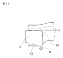
- the position of the convex portion 14 provided on the tongue piece portion 9 is provided at a position farthest from the opening end of the bulging portion 4, and the corner portion 9d of the upper end surface 9c is rounded. It is preferable to have In this case, since the contact length between the tongue piece 9 of the first plate 1 and the second plate 2 is shortened, the displacement of the second plate 2 is suppressed even if interference occurs between the members.
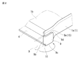
- FIG. 1 is an exploded perspective view of a main part of a flat tube 5 of a header plateless heat exchanger according to the present invention.
- FIG. 2 is an enlarged view of a portion II in FIG.
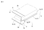
- FIG. 3 is a perspective view of the main part of the flat tube 5 assembled.
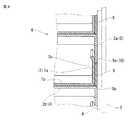
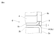
- FIG. 4 is a cross-sectional view of the core 6 made of a laminated body of the flat tubes 5 at the IV-IV position in FIG.
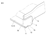
- FIG. 5 is a perspective view of the main part of the first plate 1 used in the second embodiment of the present invention.
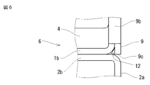
- FIG. 6 is a side view of the main part of the flat tube 5.
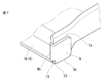
- FIG. 7 is a perspective view of an essential part of the first plate 1 used in the third embodiment of the present invention.
- FIG. 8 is a side view of an essential part of the flat tube 5 used in the fourth embodiment of the present invention.
- FIG. 9 is a perspective view of a main part of the first plate 1 used in the embodiment.
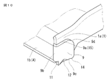
- FIG. 10 is a perspective view of an essential part of the first plate 1 used in the fifth embodiment of the present invention.
- FIG. 11 is an explanatory view when the roundness of the corner of the tongue piece portion 9 is increased, showing the operation of the embodiment.
- FIG. 12 is an explanatory view showing the operation of the embodiment when the roundness of the corner of the tongue piece 9 is small.
- FIG. 13 is a cross-sectional view of an essential part showing a conventional header plateless heat exchanger.
- this header plateless heat exchanger is used as an EGR cooler or a condenser, and gas is guided to the header tank 8 side, which circulates in the flat tube 5, and the outer side of the flat tube 5 and the casing 7.
- the cooling water flows into the area surrounded by the gas and heat exchange is performed between the gas and the cooling water.
- This heat exchanger forms the core 6 by laminating the flat tubes 5 whose both ends swell in the thickness direction at the swelled portion 4, and does not require a header plate.
- a pair of header tanks 8 are fitted on both ends of the core 6 in the longitudinal direction as shown in FIG.
- the casing 7 is fitted on the outer periphery of the core 6 through the opening of the header tank 8.
- the casing 7 includes, as an example, a casing body formed in a U-shaped cross section and an end lid that closes the opening thereof, and the whole is formed in a cylindrical shape.
- the casing body is provided with a pair of cooling water outlets and a pair of pipes connected thereto.
- the header tank 8 is fitted on both ends of the core 6 and the casing 7 is fitted on the outside of the header tank 8.
- the casing 7 is fitted on the core 6,
- a header tank 8 may be fitted on the outside of the casing 7. Even in that case, the header tank 8 is arranged at both ends of the core 6, which is the configuration described in claim 1. Furthermore, the casing and the header tank may be integrated.
- header tanks 8 are arranged at both ends of the core 6, which is the configuration described in claim 1.
- the members used in the manufacture of these header plateless heat exchangers are formed by pressing a metal plate (aluminum, aluminum alloy, steel plate, etc.), and at least one side of the surface layer is coated with a brazing material or The coated ones are used, and after assembling the parts, they are brazed together in a high temperature furnace.
- the characteristic part in this invention exists in the flat tube 5 which comprises the core 6.
- the flat tube 5 used in the present invention comprises a fitting body of a pair of upper and lower first plate 1 and second plate 2 formed in a groove shape, and both longitudinal ends of both plates 1 and 2 expand in the thickness direction.
- the bulging part 4 is formed there.
- the inner surface of the side wall 2 a of the second plate 2 is fitted on the outer surface of the pair of side walls 1 a of the first plate 1.
- the tongue piece part 9 is integrally extended and formed in the side wall 1a of the longitudinal direction both ends of the 1st plate 1 via the bending part 9b.
- the tongue piece 9 is folded outward and overlapped with the outer surface of the side wall 1 a of the first plate 1, and the upper end surface 9 a of the tongue piece 9 becomes a seating surface 15.
- the seat surface 15 corresponds to the stepped portion 10 (see FIG. 13) of the conventional flat tube, on which the seat portion 2c of the side wall 2a of the second plate 2 is seated.
- the lower end surface 9c of the tongue piece portion 9 is flush with the outer surface of the groove bottom 1b of the bulging portion 4 of the first plate 1, as shown in FIG.
- the notch part 11 is provided in the lower end part of the bending part 9b, and the tongue piece part 9 is easily turned back. Further, as shown in FIGS.
- both plates 1 and 2 are facilitated by notching the seating portion 2c of the second plate 2 into a shape that matches the seating surface 15 of the tongue piece portion 9. .
- the flat tubes 5 configured as described above are stacked at the positions of the bulging portions 4 to form the cores 6 and the openings of the header tanks 8 are fitted to both ends in the longitudinal direction, the state shown in FIG. 4 is obtained.
- the tongue piece portion 9 can be in close contact with the inner peripheral surface of the header tank 8 without any gap over the entire length in the height direction. it can.
- the outer surface of the side wall 2a of the second plate 2 fitted to the upper end surface 9a is also in close contact with the inner peripheral surface of the header tank 8 over substantially the entire length except for the corner portion with the groove bottom 2b. Become. For this reason, when brazing each component, it is possible to reduce as much as possible the locations where brazing occurs, so that the air tightness and liquid tightness around the header tank 8 of the heat exchanger can be improved.
- FIG. 5 and 6 show a second embodiment of the present invention.
- This example is different from the first embodiment in that a recess 12 is provided at the lower end of the tongue piece 9 in the direction of the side wall 1a of the first plate 1.
- the concave portion 12 is provided in the thickness direction by driving a part of the lower end portion of the tongue piece portion 9 (in this example, near the opening of the flat tube 5).
- the clearance gap between the R part of the 1st plate 1 and the tongue piece part 9 can be partially filled up, and a brazing can be prevented further as much as possible.
- FIG. 7 shows a third embodiment of the present invention.
- This example is different from the second embodiment in that a claw 13 bent into a plane triangle is provided instead of the recess 12 of the tongue piece 9. Also in this example, the same effect as the second embodiment can be obtained.
- the outer surface of the tongue piece 9 is in close contact with the inner peripheral surface of the header tank 8 except for the portion where the recess 12 or the claw 13 is formed. There is no risk of reducing the density.
- FIG. 8 and 9 show a fourth embodiment of the present invention.
- This example is different from the second or third embodiment described above in that a convex portion 14 is provided on the lower end surface 9c of the tongue piece 9 so as to project downward.
- FIG. 8 is an explanatory view when the core 6 is formed by the flat tube 5.
- a triangular gap formed by the tongue piece 9 can be partially filled.
- interference occurs between the corner of the second plate 2 and the convex portion 14 of the tongue piece 9, and as shown in FIG.
- the corner of the tongue piece 9 with the bent portion 9 b as a fulcrum. 9d is pushed up by ⁇ , and there is a possibility that the fitting portion with the second plate 2 is displaced.
- the position of the convex portion 14 provided on the tongue piece portion 9 is provided at a position farthest from the opening end of the bulging portion 4, and at the corner portion 9 d facing the position. A large roundness is provided to reduce the push-up amount.
- FIG. 10 to 12 show a fifth embodiment of the present invention, in which a recess 12 is added to the embodiment of FIG. 9 and a triangular gap inside the tongue piece 9 of FIG. 8 is filled.
Landscapes
- Engineering & Computer Science (AREA)
- Physics & Mathematics (AREA)
- Thermal Sciences (AREA)
- Mechanical Engineering (AREA)
- General Engineering & Computer Science (AREA)
- Geometry (AREA)
- Details Of Heat-Exchange And Heat-Transfer (AREA)
- Heat-Exchange Devices With Radiators And Conduit Assemblies (AREA)
Priority Applications (3)
| Application Number | Priority Date | Filing Date | Title |
|---|---|---|---|
| EP14871734.1A EP3086072B1 (en) | 2013-12-20 | 2014-12-19 | Header plateless heat exchanger |
| US15/106,040 US9903662B2 (en) | 2013-12-20 | 2014-12-19 | Header plateless heat exchanger |
| CN201480065739.9A CN105814393B (zh) | 2013-12-20 | 2014-12-19 | 无集管板型热交换器 |
Applications Claiming Priority (2)
| Application Number | Priority Date | Filing Date | Title |
|---|---|---|---|
| JP2013-264012 | 2013-12-20 | ||
| JP2013264012A JP6209078B2 (ja) | 2013-12-20 | 2013-12-20 | ヘッダプレートレス型熱交換器 |
Publications (1)
| Publication Number | Publication Date |
|---|---|
| WO2015093625A1 true WO2015093625A1 (ja) | 2015-06-25 |
Family
ID=53402959
Family Applications (1)
| Application Number | Title | Priority Date | Filing Date |
|---|---|---|---|
| PCT/JP2014/084739 Ceased WO2015093625A1 (ja) | 2013-12-20 | 2014-12-19 | ヘッダプレートレス型熱交換器 |
Country Status (5)
| Country | Link |
|---|---|
| US (1) | US9903662B2 (enExample) |
| EP (1) | EP3086072B1 (enExample) |
| JP (1) | JP6209078B2 (enExample) |
| CN (1) | CN105814393B (enExample) |
| WO (1) | WO2015093625A1 (enExample) |
Families Citing this family (6)
| Publication number | Priority date | Publication date | Assignee | Title |
|---|---|---|---|---|
| DE102014219056A1 (de) * | 2014-09-22 | 2016-05-04 | Mahle International Gmbh | Wärmeübertrager |
| WO2018159859A1 (ja) * | 2017-03-03 | 2018-09-07 | 株式会社ティラド | ドロンカップ型熱交換器 |
| JP6696928B2 (ja) | 2017-03-23 | 2020-05-20 | 日本エイアンドエル株式会社 | ポリカーボネート改質剤、改質されたポリカーボネート樹脂、及び改質されたポリカーボネート樹脂の製造方法 |
| DE102017218971B4 (de) * | 2017-10-24 | 2021-12-23 | Hanon Systems | Abgasrückführsystem |
| CN111512109B (zh) * | 2017-12-27 | 2021-12-24 | 株式会社T.Rad | 无集管板型热交换器 |
| EP3726176B1 (en) | 2019-04-15 | 2023-11-08 | Borgwarner Emissions Systems Spain, S.L.U. | Exhaust gas recirculation heat exchanger assembly |
Citations (6)
| Publication number | Priority date | Publication date | Assignee | Title |
|---|---|---|---|---|
| US20060219394A1 (en) * | 2005-04-01 | 2006-10-05 | Martin Michael A | Stacked-tube heat exchanger |
| JP2008275246A (ja) * | 2007-04-27 | 2008-11-13 | T Rad Co Ltd | ヘッダプレートレス熱交換器 |
| JP2011002133A (ja) | 2009-06-17 | 2011-01-06 | Denso Corp | 高温ガス冷却用熱交換器 |
| JP2011038752A (ja) * | 2009-08-18 | 2011-02-24 | T Rad Co Ltd | ヘッダプレートレス型の熱交換器 |
| JP2011043257A (ja) * | 2009-08-19 | 2011-03-03 | T Rad Co Ltd | ヘッダプレートレス型の熱交換器 |
| JP2011232020A (ja) | 2010-04-09 | 2011-11-17 | Denso Corp | 排気熱交換装置 |
Family Cites Families (15)
| Publication number | Priority date | Publication date | Assignee | Title |
|---|---|---|---|---|
| FR390904A (fr) * | 1908-06-04 | 1908-10-17 | Loziano Et Finet Soc | Mode de fabrication de radiateurs genre nid d'abeilles |
| US4681155A (en) * | 1986-05-01 | 1987-07-21 | The Garrett Corporation | Lightweight, compact heat exchanger |
| JPH10318695A (ja) * | 1997-05-19 | 1998-12-04 | Zexel Corp | 熱交換器 |
| FR2806469B1 (fr) * | 2000-03-20 | 2002-07-19 | Packinox Sa | PROCEDE d4ASSEMBLAGE DES PLAQUES D'UN FAISCEAU DE PLAQUES ET FAISCEAU DE PLAQUES REALISE PAR UN TEL PROCEDE |
| DE10033070A1 (de) * | 2000-03-31 | 2002-01-17 | Modine Mfg Co | Kühler für Kraftfahrzeuge sowie Herstellungsverfahren |
| DE10103570A1 (de) * | 2001-01-26 | 2002-08-01 | Modine Mfg Co | Wärmetauscher und Herstellungsverfahren |
| DE60217515T2 (de) * | 2001-06-08 | 2007-11-15 | Showa Denko K.K. | Metallplatte zur herstellung eines flachrohrs, flachrohr und verfahren zur herstellung des flachrohrs |
| DE10147192A1 (de) * | 2001-09-25 | 2003-04-17 | Modine Mfg Co | Wärmeaustauscher mit einem Rippen-Flachrohr-Block und Herstellungsverfahren |
| JP4264217B2 (ja) * | 2001-09-25 | 2009-05-13 | シャープ株式会社 | 着色層付き基板 |
| JP2009063223A (ja) * | 2007-09-06 | 2009-03-26 | Denso Corp | 熱交換器 |
| JP5519311B2 (ja) * | 2010-02-09 | 2014-06-11 | 株式会社ティラド | ヘッダプレートレス用熱交換器の偏平チューブ |
| JP5527169B2 (ja) * | 2010-11-11 | 2014-06-18 | 株式会社デンソー | 熱交換器用チューブ |
| JP5792591B2 (ja) * | 2011-10-31 | 2015-10-14 | 株式会社ティラド | ヘッダープレートレス熱交換器の偏平チューブ |
| JP2015105818A (ja) * | 2013-12-02 | 2015-06-08 | 株式会社ティラド | ヘッダプレートレス型熱交換器 |
| DE102014219093A1 (de) * | 2014-09-22 | 2016-03-24 | Mahle International Gmbh | Wärmetauscher |
-
2013
- 2013-12-20 JP JP2013264012A patent/JP6209078B2/ja not_active Expired - Fee Related
-
2014
- 2014-12-19 WO PCT/JP2014/084739 patent/WO2015093625A1/ja not_active Ceased
- 2014-12-19 US US15/106,040 patent/US9903662B2/en active Active
- 2014-12-19 CN CN201480065739.9A patent/CN105814393B/zh not_active Expired - Fee Related
- 2014-12-19 EP EP14871734.1A patent/EP3086072B1/en not_active Not-in-force
Patent Citations (6)
| Publication number | Priority date | Publication date | Assignee | Title |
|---|---|---|---|---|
| US20060219394A1 (en) * | 2005-04-01 | 2006-10-05 | Martin Michael A | Stacked-tube heat exchanger |
| JP2008275246A (ja) * | 2007-04-27 | 2008-11-13 | T Rad Co Ltd | ヘッダプレートレス熱交換器 |
| JP2011002133A (ja) | 2009-06-17 | 2011-01-06 | Denso Corp | 高温ガス冷却用熱交換器 |
| JP2011038752A (ja) * | 2009-08-18 | 2011-02-24 | T Rad Co Ltd | ヘッダプレートレス型の熱交換器 |
| JP2011043257A (ja) * | 2009-08-19 | 2011-03-03 | T Rad Co Ltd | ヘッダプレートレス型の熱交換器 |
| JP2011232020A (ja) | 2010-04-09 | 2011-11-17 | Denso Corp | 排気熱交換装置 |
Also Published As
| Publication number | Publication date |
|---|---|
| CN105814393B (zh) | 2018-03-30 |
| JP2015121334A (ja) | 2015-07-02 |
| EP3086072A1 (en) | 2016-10-26 |
| CN105814393A (zh) | 2016-07-27 |
| US9903662B2 (en) | 2018-02-27 |
| EP3086072B1 (en) | 2018-08-29 |
| EP3086072A4 (en) | 2017-09-13 |
| JP6209078B2 (ja) | 2017-10-04 |
| US20160320139A1 (en) | 2016-11-03 |
Similar Documents
| Publication | Publication Date | Title |
|---|---|---|
| CN110686538B (zh) | 无集管板型热交换器芯的结构 | |
| JP4602714B2 (ja) | 熱交換器 | |
| WO2015093625A1 (ja) | ヘッダプレートレス型熱交換器 | |
| JP5989619B2 (ja) | ヘッダープレートレス熱交換器のタンク構造 | |
| JP2006189206A (ja) | 熱交換器 | |
| WO2015037688A1 (ja) | ヘッダープレートレス熱交換器のタンク構造 | |
| JP2008275244A (ja) | 熱交換器の製造方法および熱交換器 | |
| WO2015083494A1 (ja) | ヘッダプレートレス型熱交換器 | |
| JP2005221175A (ja) | 積層型熱交換器 | |
| JP5792591B2 (ja) | ヘッダープレートレス熱交換器の偏平チューブ | |
| JP2003021488A (ja) | 熱交換器のタンク構造 | |
| JP7091308B2 (ja) | ドロンカップ型熱交換器 | |
| WO2015093624A1 (ja) | ヘッダプレートレス型熱交換器 | |
| JP2012159211A (ja) | 熱交換器 | |
| WO2015056812A1 (ja) | ヘッダプレートレス型熱交換器 | |
| JP6276114B2 (ja) | ヘッダプレートレス熱交換器用偏平チューブ | |
| JP6731266B2 (ja) | 熱交換器 | |
| JP2002062084A (ja) | 熱交換器 | |
| JP7689410B2 (ja) | 熱交換器 | |
| JP2007147173A (ja) | 熱交換器およびその製造方法 | |
| JP2016008726A (ja) | ヘッダプレートレス熱交換器用偏平チューブ | |
| JP4787511B2 (ja) | 熱交換器の接合構造及びその接合方法 | |
| JP2012149794A (ja) | チューブプレートレス熱交換器のろう付け構造 | |
| JP2010139193A (ja) | 熱交換器用ヘッダタンク及びその製造方法 | |
| JP2002257494A (ja) | 一体型熱交換器のタンク構造 |
Legal Events
| Date | Code | Title | Description |
|---|---|---|---|
| 121 | Ep: the epo has been informed by wipo that ep was designated in this application |
Ref document number: 14871734 Country of ref document: EP Kind code of ref document: A1 |
|
| REEP | Request for entry into the european phase |
Ref document number: 2014871734 Country of ref document: EP |
|
| WWE | Wipo information: entry into national phase |
Ref document number: 2014871734 Country of ref document: EP |
|
| NENP | Non-entry into the national phase |
Ref country code: DE |
|
| WWE | Wipo information: entry into national phase |
Ref document number: 15106040 Country of ref document: US |