WO2015093548A1 - ダンパー - Google Patents
ダンパー Download PDFInfo
- Publication number
- WO2015093548A1 WO2015093548A1 PCT/JP2014/083468 JP2014083468W WO2015093548A1 WO 2015093548 A1 WO2015093548 A1 WO 2015093548A1 JP 2014083468 W JP2014083468 W JP 2014083468W WO 2015093548 A1 WO2015093548 A1 WO 2015093548A1
- Authority
- WO
- WIPO (PCT)
- Prior art keywords
- piston
- housing
- seal member
- damper
- slider
- Prior art date
Links
Images


Classifications
-
- F—MECHANICAL ENGINEERING; LIGHTING; HEATING; WEAPONS; BLASTING
- F16—ENGINEERING ELEMENTS AND UNITS; GENERAL MEASURES FOR PRODUCING AND MAINTAINING EFFECTIVE FUNCTIONING OF MACHINES OR INSTALLATIONS; THERMAL INSULATION IN GENERAL
- F16F—SPRINGS; SHOCK-ABSORBERS; MEANS FOR DAMPING VIBRATION
- F16F9/00—Springs, vibration-dampers, shock-absorbers, or similarly-constructed movement-dampers using a fluid or the equivalent as damping medium
- F16F9/02—Springs, vibration-dampers, shock-absorbers, or similarly-constructed movement-dampers using a fluid or the equivalent as damping medium using gas only or vacuum
- F16F9/0209—Telescopic
- F16F9/0218—Mono-tubular units
-
- A—HUMAN NECESSITIES
- A47—FURNITURE; DOMESTIC ARTICLES OR APPLIANCES; COFFEE MILLS; SPICE MILLS; SUCTION CLEANERS IN GENERAL
- A47B—TABLES; DESKS; OFFICE FURNITURE; CABINETS; DRAWERS; GENERAL DETAILS OF FURNITURE
- A47B88/00—Drawers for tables, cabinets or like furniture; Guides for drawers
- A47B88/50—Safety devices or the like for drawers
- A47B88/57—Safety devices or the like for drawers preventing complete withdrawal of the drawer
-
- F—MECHANICAL ENGINEERING; LIGHTING; HEATING; WEAPONS; BLASTING
- F16—ENGINEERING ELEMENTS AND UNITS; GENERAL MEASURES FOR PRODUCING AND MAINTAINING EFFECTIVE FUNCTIONING OF MACHINES OR INSTALLATIONS; THERMAL INSULATION IN GENERAL
- F16F—SPRINGS; SHOCK-ABSORBERS; MEANS FOR DAMPING VIBRATION
- F16F7/00—Vibration-dampers; Shock-absorbers
- F16F7/08—Vibration-dampers; Shock-absorbers with friction surfaces rectilinearly movable along each other
- F16F7/09—Vibration-dampers; Shock-absorbers with friction surfaces rectilinearly movable along each other in dampers of the cylinder-and-piston type
- F16F7/095—Vibration-dampers; Shock-absorbers with friction surfaces rectilinearly movable along each other in dampers of the cylinder-and-piston type frictional elements brought into engagement by movement along a surface oblique to the axis of the cylinder, e.g. interaction of wedge-shaped elements
-
- F—MECHANICAL ENGINEERING; LIGHTING; HEATING; WEAPONS; BLASTING
- F16—ENGINEERING ELEMENTS AND UNITS; GENERAL MEASURES FOR PRODUCING AND MAINTAINING EFFECTIVE FUNCTIONING OF MACHINES OR INSTALLATIONS; THERMAL INSULATION IN GENERAL
- F16F—SPRINGS; SHOCK-ABSORBERS; MEANS FOR DAMPING VIBRATION
- F16F9/00—Springs, vibration-dampers, shock-absorbers, or similarly-constructed movement-dampers using a fluid or the equivalent as damping medium
- F16F9/02—Springs, vibration-dampers, shock-absorbers, or similarly-constructed movement-dampers using a fluid or the equivalent as damping medium using gas only or vacuum
- F16F9/0209—Telescopic
-
- F—MECHANICAL ENGINEERING; LIGHTING; HEATING; WEAPONS; BLASTING
- F16—ENGINEERING ELEMENTS AND UNITS; GENERAL MEASURES FOR PRODUCING AND MAINTAINING EFFECTIVE FUNCTIONING OF MACHINES OR INSTALLATIONS; THERMAL INSULATION IN GENERAL
- F16F—SPRINGS; SHOCK-ABSORBERS; MEANS FOR DAMPING VIBRATION
- F16F9/00—Springs, vibration-dampers, shock-absorbers, or similarly-constructed movement-dampers using a fluid or the equivalent as damping medium
- F16F9/32—Details
- F16F9/3207—Constructional features
- F16F9/3214—Constructional features of pistons
-
- F—MECHANICAL ENGINEERING; LIGHTING; HEATING; WEAPONS; BLASTING
- F16—ENGINEERING ELEMENTS AND UNITS; GENERAL MEASURES FOR PRODUCING AND MAINTAINING EFFECTIVE FUNCTIONING OF MACHINES OR INSTALLATIONS; THERMAL INSULATION IN GENERAL
- F16F—SPRINGS; SHOCK-ABSORBERS; MEANS FOR DAMPING VIBRATION
- F16F9/00—Springs, vibration-dampers, shock-absorbers, or similarly-constructed movement-dampers using a fluid or the equivalent as damping medium
- F16F9/32—Details
- F16F9/3207—Constructional features
- F16F9/3235—Constructional features of cylinders
-
- F—MECHANICAL ENGINEERING; LIGHTING; HEATING; WEAPONS; BLASTING
- F16—ENGINEERING ELEMENTS AND UNITS; GENERAL MEASURES FOR PRODUCING AND MAINTAINING EFFECTIVE FUNCTIONING OF MACHINES OR INSTALLATIONS; THERMAL INSULATION IN GENERAL
- F16F—SPRINGS; SHOCK-ABSORBERS; MEANS FOR DAMPING VIBRATION
- F16F9/00—Springs, vibration-dampers, shock-absorbers, or similarly-constructed movement-dampers using a fluid or the equivalent as damping medium
- F16F9/32—Details
- F16F9/36—Special sealings, including sealings or guides for piston-rods
- F16F9/368—Sealings in pistons
Definitions
- This invention relates to the improvement of the damper which produces braking force by the action
- Air that includes a cylinder body that has two cylinder parts arranged side by side and a piston body that consists of piston rods that move in the two cylinder parts in an attempt to create a compact air damper that can produce a large output.
- a damper see Patent Document 1.
- the air damper of Patent Document 1 covers the entire braking force with resistance due to pressure change.
- the braking force is small at the start of the movement of the piston rod, and the braking force rapidly increases as the operation proceeds.
- the brake target may stop in the course of movement, and further, a situation may occur in which the brake is started to return to the position before movement from the middle of movement. Therefore, it is difficult to properly control the movement of the braking target throughout the entire process.
- the braking force depends on the cross-sectional area of the cylinder body, and thus there is a limit to downsizing.
- the main problem to be solved by the present invention is to provide a damper that can appropriately control the movement of the braking target in the entire process and is suitable for downsizing and thinning.
- the damper is composed of a piston having a rod and a housing for housing the piston, and a braking force is generated by the operation of the piston.
- the piston is A sealing member for the inner wall of the housing;
- a slider that is slidable with respect to the piston, and a slider that contacts the inner wall of the housing with a predetermined frictional force;
- the braking force is generated, the slider is brought into pressure contact with the seal member, and a portion of the seal member that contacts the inner wall of the housing is deformed toward the outside of the housing.
- a desired braking force is generated by the resistance due to the pressure change caused by the operation of the piston and the frictional resistance between the seal member and the housing generated by the slider deforming the seal member as described above. Can be made.
- the slider is in contact with the inner wall of the housing with a lip.
- the slider includes a pressure contact portion that is pressed against the seal member from the rod side.
- the deformation amount of the seal member is increased in accordance with the operating speed of the piston.
- the sliding amount of the slider increases in accordance with the operating speed of the piston.
- the damper comprises a piston provided with a rod and a housing for housing the piston.
- a damper to generate, The piston is A sealing member for the inner wall of the housing; The portion of the seal member that is in contact with the inner wall of the housing is deformed toward the outside of the housing when a chamber formed between the piston and the closed end of the housing becomes negative pressure. It was supposed to be.
- the cross-sectional outline shape of the housing in the direction orthogonal to the moving direction of the piston constituting each of the damper devices is flat.
- the damper according to the present invention can appropriately control the movement of the braking target in the whole process, and is also suitable for downsizing and thinning. Further, since the braking force of the damper according to the present invention is caused by the deformation of the seal member, the structure can be simplified, and the desired force can be obtained without paying special consideration to the dimensional accuracy of each component. It has the feature that can generate braking force.
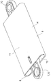
- FIG. 1 is a perspective view of a damper (first example) according to an embodiment of the present invention.
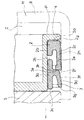
- FIG. 2 is a cross-sectional configuration diagram of the first example.
- FIG. 3 is an enlarged cross-sectional configuration diagram of the main part of the first example, and shows a state when the piston moves forward.
- FIG. 4 is an enlarged cross-sectional configuration diagram of the main part of the first example, showing a state when the piston moves forward.
- FIG. 5 is an enlarged cross-sectional configuration diagram of the main part of the first example, and shows a state when the piston moves backward.
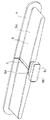
- FIG. 6 is an exploded perspective view of the first example.
- FIG. 7 is a perspective view of head parts constituting the piston of the first example.
- FIG. 8 is a perspective view of the piston of the first example.
- FIG. 9 is a perspective view of the piston of the first example, and shows the piston from the right side of FIG.
- FIG. 10 is a cross-sectional view of a damper (second example) according to another embodiment of the present invention.
- FIG. 11 is an exploded perspective view of the second example.
- FIG. 12 is a perspective view of parts constituting the piston of the second example.
- FIG. 13 is an enlarged cross-sectional configuration diagram of a main part of a damper (third example) according to another embodiment of the present invention, and shows a state when the piston moves forward.
- FIG. 14 is an enlarged cross-sectional configuration diagram of the main part of the third example, showing a state when the piston is moved backward.
- the damper according to this embodiment generates a braking force for the operation of the piston P constituting the damper, that is, the movement or relative movement of the piston P, and is typically a braking target.
- the braking force is applied to the movement of the braking object, and the movement of the braking object is slow, high-grade, It is used in order not to make things moderate or excessive.
- Such a damper comprises a piston P provided with a rod 1 and a housing H in which the piston P is accommodated.
- a damper links either one of the rod 1 and the housing H directly or indirectly to the braking object side, and directly or indirectly connects the other of these to the side that movably supports the braking object. By linking, it is combined with an article having such a braking object.
- the housing H has a cylindrical shape with one end open and the other end closed.
- the housing H has a flat cylindrical shape with a significantly reduced thickness. More specifically, in the illustrated example, the housing H has a substantially rectangular cross section perpendicular to the cylinder axis.
- the side wall 8 constituting the thickness side of the housing H has a curved shape with the outer side of the housing H being the curved outer side.
- a bracket portion 10 for the linkage is formed outside the closed end 9 of the housing H.
- the rod 1 has a long rod shape in the moving direction of the piston P.
- a bracket portion 1a for the linkage is formed at one end of the rod 1 located outside the housing H.
- the piston P includes a seal member 2 for the inner wall of the housing H, and a slider 3 that is slidable with respect to the piston P and that contacts the inner wall of the housing H with a predetermined frictional force.
- the piston P includes a first flange 4 that faces the closed end 9 of the housing H, and a second flange 5 that holds the seal member 2 and the slider 3 between the first flange 4. ing.
- the second flange 5 is located behind the first flange 4, that is, on the open end 12 side of the housing H.
- Both the first flange 4 and the second flange 5 have the same cross-sectional outline shape in the direction perpendicular to the moving direction x (see FIG. 2) of the piston P, that is, the direction along the cylinder axis of the housing H.
- the shape is complementary to the cross-sectional inner shape of the housing H, whereby the piston P is guided by the inner wall of the housing H and reciprocates in the direction along the cylinder axis of the housing H.
- the second flange 5 is formed at the other end of the rod 1.
- the first flange 4 is formed on the head part 6 which is separate from the rod 1 (see FIGS. 6 and 7).
- the head part 6 has a plate-like body 6 a whose plate surface faces the side wall on the width side of the housing H.
- the first flange 4 with the flange end positioned on the outer side of the outer surface of the barrel portion 6a at each position around the barrel portion 6a is integrally formed on the side of the barrel portion 6a facing the closed end 9 of the housing H. Is formed.
- an end portion of the trunk portion 6a directed to the open end 12 of the housing H, which is located on the cylinder axis of the housing H, includes a head portion 6c and a neck portion 6d, and a neck portion.
- a male joint portion 6b integrated with the trunk portion 6a via the portion 6d is formed.
- the first recess 5b that receives and holds the head 6c of the male joint portion 6b and the neck portion 6c of the male joint portion 6b are located on the cylindrical axis of the housing H.
- a female joint portion 5a is formed which includes the second recess 5c that is received and held and opened outward at the end of the second flange 5 that faces the closed end 9 of the housing H (see FIG. 6). .
- the male seal member 2 and the slider 3 each having a flat ring shape are combined with the head part 6 so as to surround the body part 6a of the head part 6, and then the male part of the head part 6 is used.
- a piston P configured to hold the seal member 2 and the slider 3 between the first flange 4 and the second flange 5 is formed. It has become.
- reference numeral 6 e denotes a thinned portion inside the head part 6.
- the heel seal member 2 is typically made of rubber or plastic with rubber-like elasticity, and has a flat ring shape. By inserting the body portion 6a of the head part 6 into the seal member 2 from the male joint portion 6b side, the head part 6 and the seal member 2 are combined.
- the seal member 2 has a front end surface 2a for the first flange 4, an inner surface 2b for the outer surface of the head part 6, and an outer surface 2c for the inner wall of the housing H (see FIG. 3).
- a circumferential groove 2d is formed between the inner surface 2b and the outer surface 2c.
- the outer surface side sandwiching the circumferential groove 2d extends toward the open end 12 side of the housing H over the entire circumferential direction of the seal member 2, whereby the seal member 2 includes a skirt-like portion 2e.
- the outer surface 2c of the seal member 2 is larger than the inner surface 2b.
- the outer surface 2c of the seal member 2 is inclined so as to gradually increase the thickness of the seal member 2 from the front end surface 2a toward the terminal 2f of the skirt-like portion 2e (see FIG. 4).
- a circumferential protrusion 2g is formed on the front end surface 2a of the seal member 2.
- the heel slider 3 is typically made of plastic and has a flat ring shape. From the state in which the head part 6 and the seal member 2 are combined as described above, the body part 6a of the head part 6 is inserted into the inside of the slider 3 from the male joint part 6b side. 3 is combined.
- the slider 3 has a short cylindrical shape in which the cross-sectional outline shape orthogonal to the moving direction x of the piston P is complementary to the cross-sectional outline shape of the body portion 6a of the head part 6 in the same direction.
- the lip 3d is a circular fin-like body formed so as to surround the base 3a.
- the lip 3d is a base portion integrated with the outer surface portion of the base 3a between the front end 3b located on the seal member 2 side of the base 3a and the rear end 3c located on the open end 12 side of the housing H. 3e and an extending portion 3f extending from the base portion 3e toward the open end 12 of the housing H (see FIG. 4).
- a shoulder 3h is formed between the base 3e and the extension 3f.
- the extension 3f has an inclination that gradually increases the distance from the base 3a as it goes from the shoulder 3h toward the terminal 3g.
- the seal member 2 and the slider 3 are both held in a state where slight movement along the movement direction x of the piston P is allowed.
- the outer surface 2c of the seal member 2 is in contact with the inner wall of the housing H over the entire circumference, and the extending portion 3f of the slider 3 is also in contact with the inner wall of the housing H on the terminal 3g side over the entire circumference. .
- the portion between the front end 3b of the base 3a of the slider 3 and the base 3e of the lip 3d is located inside the skirt-like portion 2e of the seal member 2, and the shoulder 3h of the lip 3d of the slider 3 is It faces the terminal 2f of the skirt-like portion 2e of the seal member 2 (FIGS. 2 to 5).
- the slider 3 when the braking force is generated, the slider 3 is in pressure contact with the seal member 2, and the portion of the seal member 2 that is in contact with the inner wall of the housing H is outside the housing H. It is designed to deform toward.
- the slider 3 becomes difficult to move in the forward movement direction due to the shape of the lip 3d, so that the shoulder 3h of the slider 3 is the skirt-shaped portion 2e of the seal member 2.
- the circumferential protrusion 2g formed on the front end surface 2a of the seal member 2 is brought into close contact with the first flange 4 so that the space between the front end surface 2a and the first flange 4 is sealed.
- the shape portion 2e is deformed outward to seal between the outer surface 2c of the seal member 2 and the inner wall of the housing H (FIGS. 3 and 4).
- the ventilation to the chamber C is performed at the position where the head flange 6 constituting the piston P is positioned on the cylinder axis of the housing H, and the first flange 4. Is limited to the air passage formed by the groove 7 (see FIGS. 6 to 8) formed from the edge of the body 6a toward the open end 12 of the housing H in the body 6a. Resistance is generated. The frictional resistance is generated by the outward deformation of the skirt-like portion 2e of the seal member 2. That is, the slider 3 includes a pressure contact portion that is pressed against the seal member 2 from the rod 1 side. In the illustrated example, the shoulder portion 3h functions as this pressure contact portion.
- the damper according to this embodiment is a speed response type or load response type damper that changes the braking force in accordance with the moving speed of the braking target to be braked.
- the brake target may stop in the course of movement, or may even start to return to the position before movement from the middle of movement. In some cases, it is difficult to properly control the movement of the braking target throughout the entire process.
- the damper according to this embodiment since the braking force is covered by the resistance due to the pressure change and the frictional resistance, the movement of the braking target can be properly controlled in the entire process. . That is, according to the damper according to this embodiment, the braking target stops in the course of the forward movement, or even starts to return from the middle of the forward movement to the position before the forward movement, etc. Can be prevented as much as possible.
- the damper according to this embodiment has a feature that even if the cross-sectional area of the housing H is reduced, a desired braking force is easily generated, and the size and thickness can be easily reduced.
- the chamber C is communicated through a gap y between the first flange 4 and the front end surface 2a of the seal member 2 in addition to the air passage formed by the groove 7.
- a groove 2h is formed on the outer surface of the seal member 2 along the moving direction x of the piston P.
- the groove 2h opens the groove end on the chamber C side, and the open end 12 of the housing H is opened.
- the groove end on the side is closed, when the piston P returns, a part of the seal member 2 is deformed inward at the position where the groove 2h is formed due to an increase in pressure on the chamber C side. Exhaust gas comes from C.
- the damper does not generate a special braking force.
- the situation in which the braking target moves backward from the middle of the forward movement toward the position before the forward movement does not occur because the air passage of the chamber C is expanded at the same time as the piston P tries to move backward. .
- the second example of the damper shown in FIGS. 10 to 12 has a larger housing H and piston P than the first example of damper.
- Reference numeral 13 in the figure denotes a head corresponding to the head part 6 of the first example, and is integrated with the rod 1.
- Reference numeral 14 in the figure denotes a claw portion that functions in the same manner as the second flange 5 of the first example, and reference numeral 15 denotes a cap that closes the open end 12 of the housing H.
- the air passage that always communicates the chamber C with the outside is an orifice 16 that penetrates the head. Since the remaining components of the damper of the second example are substantially the same as the damper of the first example, the same components are shown in FIGS. 10 to 12 showing the damper of the second example.
- the same reference numerals as those used in FIGS. 1 to 9 showing the damper of the example are attached, and the description thereof is omitted.
- the damper of the third example shown in FIGS. 13 and 14 has a configuration in which the piston P does not include the slider 3.
- the remaining configuration of the damper of the third example is substantially the same as that of the damper of the first example, and the description thereof is omitted.
- the portion of the seal member 2 that is in contact with the inner wall of the housing H has a negative chamber C formed between the piston P and the closed end 9 of the housing H. When the pressure is reached, it is deformed toward the outside of the housing H (FIG. 13).
- each of the damper devices described above easily generates a desired braking force even if the cross-sectional area of the housing H is reduced as described above, the cross-section of the housing in a direction orthogonal to the moving direction of the piston.
- the outer shape is flat and thin.
- the present invention is not limited to the embodiment described above, but includes all embodiments that can achieve the object of the present invention.
- the entire contents of the specification, claims, drawings and abstract of Japanese Patent Application No. 2013-262149 filed on Dec. 19, 2013 are incorporated herein by reference as the disclosure of the specification of the present invention. Is.
Abstract
Description
前記ピストンは、
前記ハウジングの内壁に対するシール部材と、
前記ピストンに対して摺動可能に備えられると共に、前記ハウジングの内壁に所定の摩擦力をもって接するスライダとを備えており、
前記制動力発生時に、前記スライダが前記シール部材に圧接して、前記シール部材における前記ハウジングの内壁に接する部分が前記ハウジングの外側に向けて変形するようになっているものとした。
前記ピストンは、
前記ハウジングの内壁に対するシール部材を備えており、
前記シール部材における前記ハウジングの内壁に接する部分が、前記ピストンと前記ハウジングの閉塞端との間に形成されるチャンバーが負圧になったときに、前記ハウジングの外側に向けて変形するようになっているものとした。
の作動速度に応じて、前記シール部材2の変形量が増加するようになる。
2013年12月19日に出願された日本国特願2013-262149号の明細書、特許請求の範囲、図面及び要約書の全内容をここに引用し、本発明の明細書の開示として、取り入れるものである。
Claims (8)
- ロッドを備えたピストンと、このピストンを納めるハウジングとからなり、前記ピストンの作動により制動力を生じさせるダンパーであって、
前記ピストンは、
前記ハウジングの内壁に対するシール部材と、
前記ピストンに対して摺動可能に備えられると共に、前記ハウジングの内壁に所定の摩擦力をもって接するスライダとを備えており、
前記制動力発生時に、前記スライダが前記シール部材に圧接して、前記シール部材における前記ハウジングの内壁に接する部分が前記ハウジングの外側に向けて変形するようになっている、ダンパー。 - 前記スライダは、前記ハウジングの内壁にリップをもって接するようになっている、請求項1に記載のダンパー。
- 前記スライダは、前記シール部材に対し前記ロッド側から圧接される圧接部を備えてなる、請求項1又は請求項2に記載のダンパー。
- 前記ピストンの作動速度に応じて、前記シール部材の変形量が増加するようにしてある、請求項1~請求項3のいずれか1項に記載のダンパー。
- 前記ピストンの作動速度に応じて、前記スライダの摺動量が増加するようにしてある、請求項1~請求項3のいずれか1項に記載のダンパー。
- ロッドを備えたピストンと、このピストンを納めるハウジングとからなり、前記ピストンの作動により制動力を生じさせるダンパーであって、
前記ピストンは、
前記ハウジングの内壁に対するシール部材を備えており、
前記シール部材における前記ハウジングの内壁に接する部分が、前記ピストンと前記ハウジングの閉塞端との間に形成されるチャンバーが負圧になったときに、前記ハウジングの外側に向けて変形するようになっている、ダンパー。 - 前記ピストンの作動速度に応じて、前記シール部材の変形量が増加するようにしてある、請求項6に記載のダンパー。
- 前記ピストンの移動方向に直交する向きのハウジングの断面外郭形状が扁平となっている、請求項1~請求項7のいずれか1項に記載のダンパー。
Priority Applications (4)
| Application Number | Priority Date | Filing Date | Title |
|---|---|---|---|
| JP2015553593A JP6138278B2 (ja) | 2013-12-19 | 2014-12-17 | ダンパー |
| EP14870932.2A EP3085987B1 (en) | 2013-12-19 | 2014-12-17 | Damper |
| CN201480068816.6A CN105829758B (zh) | 2013-12-19 | 2014-12-17 | 阻尼器 |
| US15/105,989 US9850975B2 (en) | 2013-12-19 | 2014-12-17 | Damper |
Applications Claiming Priority (2)
| Application Number | Priority Date | Filing Date | Title |
|---|---|---|---|
| JP2013262149 | 2013-12-19 | ||
| JP2013-262149 | 2013-12-19 |
Publications (1)
| Publication Number | Publication Date |
|---|---|
| WO2015093548A1 true WO2015093548A1 (ja) | 2015-06-25 |
Family
ID=53402892
Family Applications (1)
| Application Number | Title | Priority Date | Filing Date |
|---|---|---|---|
| PCT/JP2014/083468 WO2015093548A1 (ja) | 2013-12-19 | 2014-12-17 | ダンパー |
Country Status (6)
| Country | Link |
|---|---|
| US (1) | US9850975B2 (ja) |
| EP (1) | EP3085987B1 (ja) |
| JP (1) | JP6138278B2 (ja) |
| KR (1) | KR101647562B1 (ja) |
| CN (1) | CN105829758B (ja) |
| WO (1) | WO2015093548A1 (ja) |
Cited By (5)
| Publication number | Priority date | Publication date | Assignee | Title |
|---|---|---|---|---|
| WO2016185983A1 (ja) * | 2015-05-15 | 2016-11-24 | 株式会社ニフコ | ダンパー |
| WO2017047775A1 (ja) * | 2015-09-18 | 2017-03-23 | 株式会社ニフコ | ダンパー |
| WO2018079064A1 (ja) * | 2016-10-26 | 2018-05-03 | 株式会社ニフコ | ダンパー |
| WO2018190256A1 (ja) * | 2017-04-12 | 2018-10-18 | 株式会社パイオラックス | ダンパー |
| WO2019188807A1 (ja) * | 2018-03-28 | 2019-10-03 | 株式会社パイオラックス | ダンパー |
Families Citing this family (4)
| Publication number | Priority date | Publication date | Assignee | Title |
|---|---|---|---|---|
| DK179577B1 (en) | 2016-10-10 | 2019-02-20 | Widex A/S | Binaural hearing aid system and a method of operating a binaural hearing aid system |
| CN108223661B (zh) * | 2018-01-16 | 2018-12-11 | 罗茜 | 一种变形阻尼器 |
| CN108374859B (zh) * | 2018-02-08 | 2020-11-17 | 江苏三尔汽车部件有限公司 | 一种减震器 |
| JP7449885B2 (ja) * | 2021-02-15 | 2024-03-14 | 株式会社ニフコ | ダンパー装置 |
Citations (4)
| Publication number | Priority date | Publication date | Assignee | Title |
|---|---|---|---|---|
| JP2000088028A (ja) * | 1998-09-10 | 2000-03-28 | Piolax Inc | エアダンパー |
| JP2002286076A (ja) * | 2001-01-09 | 2002-10-03 | Julius Blum Gmbh | 家具などの可動部分用の制動・緩衝装置 |
| EP1662170A1 (de) * | 2004-11-26 | 2006-05-31 | Christian Krischke-Lengersdorf | Pneumatischer Dämpfer |
| WO2007111016A1 (ja) * | 2006-03-27 | 2007-10-04 | Nifco Inc. | 速度応答型エアーダンパー |
Family Cites Families (15)
| Publication number | Priority date | Publication date | Assignee | Title |
|---|---|---|---|---|
| US4110868A (en) * | 1976-02-23 | 1978-09-05 | Yasutaka Imazaike | Air damper |
| US5070971A (en) * | 1990-04-23 | 1991-12-10 | General Motors Corporation | Molded piston for a hydraulic damper |
| JP3397923B2 (ja) * | 1995-01-25 | 2003-04-21 | エヌオーケー株式会社 | 密封装置 |
| DE19717937A1 (de) * | 1996-11-08 | 1998-05-20 | Grass Ag | Brems- und Dämpfungselement für bewegliche Möbelteile |
| US6062352A (en) * | 1998-08-24 | 2000-05-16 | Piolax, Inc. | Air damper |
| DE20122569U1 (de) | 2001-01-09 | 2006-04-27 | Julius Blum Gmbh | Brems- und Dämpfeinrichtung, insbesondere für bewegbare Möbel |
| DE50311256D1 (de) * | 2003-01-30 | 2009-04-16 | Blum Gmbh Julius | Dämpfer insbesondere für bewegliche möbelteile |
| DE10313659B3 (de) * | 2003-03-26 | 2004-09-30 | Zimmer, Günther Stephan | Pneumatische Verzögerungsvorrichtung zum Abbremsen beweglicher Möbelteile |
| DE202004009535U1 (de) * | 2004-06-16 | 2005-11-10 | Alfit Ag | Vorrichtung zur Dämpfung bzw. Abbremsung von beweglichen Möbelteilen von Möbelstücken |
| DE102004057561A1 (de) | 2004-11-30 | 2007-04-19 | Bruno Meier | Pneumatische Verzögerungseinrichtung zum Abbremsen beweglicher Möbelteile, insbesondere von Auszügen |
| DE102006040085A1 (de) * | 2006-08-28 | 2008-03-20 | Zimmer, Günther | Kostengünstig herstellbare pneumatische Verzögerungsvorrichtung |
| JP4929495B2 (ja) * | 2006-12-06 | 2012-05-09 | Smc株式会社 | ダンパ固定構造 |
| DE102008010908B4 (de) * | 2008-02-25 | 2015-05-28 | Günther Zimmer | Kolbendichtelement und Verzögerungsvorrichtung mit Kolbendichtelement |
| US20120091641A1 (en) * | 2010-10-19 | 2012-04-19 | Ching-Chuan Yang | Air pressure buffer |
| US20120175830A1 (en) * | 2011-01-07 | 2012-07-12 | Ching-Chuan Yang | Buffer |
-
2014
- 2014-12-03 KR KR1020140172266A patent/KR101647562B1/ko active IP Right Grant
- 2014-12-17 JP JP2015553593A patent/JP6138278B2/ja active Active
- 2014-12-17 WO PCT/JP2014/083468 patent/WO2015093548A1/ja active Application Filing
- 2014-12-17 EP EP14870932.2A patent/EP3085987B1/en active Active
- 2014-12-17 CN CN201480068816.6A patent/CN105829758B/zh active Active
- 2014-12-17 US US15/105,989 patent/US9850975B2/en active Active
Patent Citations (5)
| Publication number | Priority date | Publication date | Assignee | Title |
|---|---|---|---|---|
| JP2000088028A (ja) * | 1998-09-10 | 2000-03-28 | Piolax Inc | エアダンパー |
| JP3298002B2 (ja) | 1998-09-10 | 2002-07-02 | 株式会社パイオラックス | エアダンパー |
| JP2002286076A (ja) * | 2001-01-09 | 2002-10-03 | Julius Blum Gmbh | 家具などの可動部分用の制動・緩衝装置 |
| EP1662170A1 (de) * | 2004-11-26 | 2006-05-31 | Christian Krischke-Lengersdorf | Pneumatischer Dämpfer |
| WO2007111016A1 (ja) * | 2006-03-27 | 2007-10-04 | Nifco Inc. | 速度応答型エアーダンパー |
Cited By (22)
| Publication number | Priority date | Publication date | Assignee | Title |
|---|---|---|---|---|
| US10619692B2 (en) | 2015-05-15 | 2020-04-14 | Nifco Inc. | Damper |
| JP2016217389A (ja) * | 2015-05-15 | 2016-12-22 | 株式会社ニフコ | ダンパー |
| WO2016185983A1 (ja) * | 2015-05-15 | 2016-11-24 | 株式会社ニフコ | ダンパー |
| WO2017047775A1 (ja) * | 2015-09-18 | 2017-03-23 | 株式会社ニフコ | ダンパー |
| KR20170034320A (ko) * | 2015-09-18 | 2017-03-28 | 가부시키가이샤 니프코 | 댐퍼 |
| JPWO2017047775A1 (ja) * | 2015-09-18 | 2018-03-29 | 株式会社ニフコ | ダンパー |
| CN108027002B (zh) * | 2015-09-18 | 2020-05-19 | 株式会社利富高 | 阻尼器 |
| CN108027002A (zh) * | 2015-09-18 | 2018-05-11 | 株式会社利富高 | 阻尼器 |
| KR101867172B1 (ko) * | 2015-09-18 | 2018-06-12 | 가부시키가이샤 니프코 | 댐퍼 |
| US10626946B2 (en) | 2015-09-18 | 2020-04-21 | Nifco Inc. | Damper |
| WO2018079064A1 (ja) * | 2016-10-26 | 2018-05-03 | 株式会社ニフコ | ダンパー |
| CN110050142A (zh) * | 2016-10-26 | 2019-07-23 | 株式会社利富高 | 阻尼器 |
| DE112017005405T5 (de) | 2016-10-26 | 2019-07-11 | Nifco Inc. | Dämpfer |
| JP2018071595A (ja) * | 2016-10-26 | 2018-05-10 | 株式会社ニフコ | ダンパー |
| US10883557B2 (en) | 2016-10-26 | 2021-01-05 | Nifco Inc. | Damper |
| CN110050142B (zh) * | 2016-10-26 | 2021-10-01 | 株式会社利富高 | 阻尼器 |
| JPWO2018190256A1 (ja) * | 2017-04-12 | 2020-01-16 | 株式会社パイオラックス | ダンパー |
| WO2018190256A1 (ja) * | 2017-04-12 | 2018-10-18 | 株式会社パイオラックス | ダンパー |
| WO2019188807A1 (ja) * | 2018-03-28 | 2019-10-03 | 株式会社パイオラックス | ダンパー |
| JPWO2019188807A1 (ja) * | 2018-03-28 | 2021-03-18 | 株式会社パイオラックス | ダンパー |
| JP6992165B2 (ja) | 2018-03-28 | 2022-01-17 | 株式会社パイオラックス | ダンパー |
| US11459812B2 (en) | 2018-03-28 | 2022-10-04 | Piolax, Inc. | Damper |
Also Published As
| Publication number | Publication date |
|---|---|
| US9850975B2 (en) | 2017-12-26 |
| EP3085987B1 (en) | 2019-11-20 |
| EP3085987A4 (en) | 2017-10-11 |
| JPWO2015093548A1 (ja) | 2017-03-23 |
| EP3085987A1 (en) | 2016-10-26 |
| US20170002886A1 (en) | 2017-01-05 |
| JP6138278B2 (ja) | 2017-05-31 |
| CN105829758A (zh) | 2016-08-03 |
| KR20150072335A (ko) | 2015-06-29 |
| CN105829758B (zh) | 2017-10-31 |
| KR101647562B1 (ko) | 2016-08-10 |
Similar Documents
| Publication | Publication Date | Title |
|---|---|---|
| JP6138278B2 (ja) | ダンパー | |
| WO2009154183A1 (ja) | ダンパー装置 | |
| JP6576321B2 (ja) | ダンパー | |
| JP4695681B2 (ja) | シリンダ装置 | |
| JP6393234B2 (ja) | ダンパー | |
| US20180259026A1 (en) | Damper | |
| KR20210039487A (ko) | 클러치 피스톤 | |
| JP6479234B2 (ja) | ダンパー | |
| KR101461312B1 (ko) | 차량 브레이크 부스터용 키 | |
| WO2013011875A1 (ja) | ダンパー装置 | |
| KR102396904B1 (ko) | 플런저 밸브 가이드장치 | |
| KR101896505B1 (ko) | 브레이크 부스터 | |
| KR20140059664A (ko) | 브레이크 부스터 | |
| KR20110125133A (ko) | 차량용 브레이크 부스터 | |
| KR20110026983A (ko) | 차량용 브레이크 부스터 | |
| CN114941674A (zh) | 阻尼装置 | |
| KR20120106205A (ko) | 차량용 브레이크 부스터 | |
| JP2014015098A (ja) | 気圧式倍力装置 | |
| JPH0565733U (ja) | 気圧式倍力装置 | |
| KR20090078868A (ko) | 브레이크 부스터 |
Legal Events
| Date | Code | Title | Description |
|---|---|---|---|
| 121 | Ep: the epo has been informed by wipo that ep was designated in this application |
Ref document number: 14870932 Country of ref document: EP Kind code of ref document: A1 |
|
| ENP | Entry into the national phase |
Ref document number: 2015553593 Country of ref document: JP Kind code of ref document: A |
|
| WWE | Wipo information: entry into national phase |
Ref document number: 15105989 Country of ref document: US |
|
| NENP | Non-entry into the national phase |
Ref country code: DE |
|
| REEP | Request for entry into the european phase |
Ref document number: 2014870932 Country of ref document: EP |
|
| WWE | Wipo information: entry into national phase |
Ref document number: 2014870932 Country of ref document: EP |