WO2015092845A1 - Dispositif d'apport d'eau chaude de pompe à chaleur - Google Patents
Dispositif d'apport d'eau chaude de pompe à chaleur Download PDFInfo
- Publication number
- WO2015092845A1 WO2015092845A1 PCT/JP2013/083570 JP2013083570W WO2015092845A1 WO 2015092845 A1 WO2015092845 A1 WO 2015092845A1 JP 2013083570 W JP2013083570 W JP 2013083570W WO 2015092845 A1 WO2015092845 A1 WO 2015092845A1
- Authority
- WO
- WIPO (PCT)
- Prior art keywords
- water supply
- hot water
- load
- refrigerant
- capacity compressor
- Prior art date
Links
- XLYOFNOQVPJJNP-UHFFFAOYSA-N water Substances O XLYOFNOQVPJJNP-UHFFFAOYSA-N 0.000 title claims abstract description 217
- 239000003507 refrigerant Substances 0.000 claims abstract description 79
- 230000006837 decompression Effects 0.000 claims abstract description 14
- 230000008859 change Effects 0.000 claims description 36
- 238000001514 detection method Methods 0.000 claims description 17
- 230000006835 compression Effects 0.000 claims description 2
- 238000007906 compression Methods 0.000 claims description 2
- 238000009833 condensation Methods 0.000 description 12
- 230000005494 condensation Effects 0.000 description 12
- 230000007423 decrease Effects 0.000 description 11
- 238000010586 diagram Methods 0.000 description 6
- 230000006870 function Effects 0.000 description 6
- 230000000694 effects Effects 0.000 description 5
- 238000000034 method Methods 0.000 description 5
- 239000007788 liquid Substances 0.000 description 4
- 239000002826 coolant Substances 0.000 description 3
- 239000010721 machine oil Substances 0.000 description 3
- 230000009993 protective function Effects 0.000 description 3
- 238000006243 chemical reaction Methods 0.000 description 2
- 238000004851 dishwashing Methods 0.000 description 2
- 238000010438 heat treatment Methods 0.000 description 2
- 239000003921 oil Substances 0.000 description 2
- 230000000717 retained effect Effects 0.000 description 2
- 238000004088 simulation Methods 0.000 description 2
- 230000004913 activation Effects 0.000 description 1
- 238000003287 bathing Methods 0.000 description 1
- 239000012267 brine Substances 0.000 description 1
- 238000004364 calculation method Methods 0.000 description 1
- 230000003247 decreasing effect Effects 0.000 description 1
- 238000002474 experimental method Methods 0.000 description 1
- 239000008236 heating water Substances 0.000 description 1
- 238000005457 optimization Methods 0.000 description 1
- 230000008569 process Effects 0.000 description 1
- 230000009467 reduction Effects 0.000 description 1
- HPALAKNZSZLMCH-UHFFFAOYSA-M sodium;chloride;hydrate Chemical compound O.[Na+].[Cl-] HPALAKNZSZLMCH-UHFFFAOYSA-M 0.000 description 1
Images


Classifications
-
- F—MECHANICAL ENGINEERING; LIGHTING; HEATING; WEAPONS; BLASTING
- F24—HEATING; RANGES; VENTILATING
- F24H—FLUID HEATERS, e.g. WATER OR AIR HEATERS, HAVING HEAT-GENERATING MEANS, e.g. HEAT PUMPS, IN GENERAL
- F24H4/00—Fluid heaters characterised by the use of heat pumps
- F24H4/02—Water heaters
-
- F—MECHANICAL ENGINEERING; LIGHTING; HEATING; WEAPONS; BLASTING
- F24—HEATING; RANGES; VENTILATING
- F24H—FLUID HEATERS, e.g. WATER OR AIR HEATERS, HAVING HEAT-GENERATING MEANS, e.g. HEAT PUMPS, IN GENERAL
- F24H15/00—Control of fluid heaters
- F24H15/20—Control of fluid heaters characterised by control inputs
- F24H15/212—Temperature of the water
- F24H15/215—Temperature of the water before heating
-
- F—MECHANICAL ENGINEERING; LIGHTING; HEATING; WEAPONS; BLASTING
- F24—HEATING; RANGES; VENTILATING
- F24H—FLUID HEATERS, e.g. WATER OR AIR HEATERS, HAVING HEAT-GENERATING MEANS, e.g. HEAT PUMPS, IN GENERAL
- F24H15/00—Control of fluid heaters
- F24H15/20—Control of fluid heaters characterised by control inputs
- F24H15/212—Temperature of the water
- F24H15/219—Temperature of the water after heating
-
- F—MECHANICAL ENGINEERING; LIGHTING; HEATING; WEAPONS; BLASTING
- F24—HEATING; RANGES; VENTILATING
- F24H—FLUID HEATERS, e.g. WATER OR AIR HEATERS, HAVING HEAT-GENERATING MEANS, e.g. HEAT PUMPS, IN GENERAL
- F24H15/00—Control of fluid heaters
- F24H15/20—Control of fluid heaters characterised by control inputs
- F24H15/227—Temperature of the refrigerant in heat pump cycles
-
- F—MECHANICAL ENGINEERING; LIGHTING; HEATING; WEAPONS; BLASTING
- F24—HEATING; RANGES; VENTILATING
- F24H—FLUID HEATERS, e.g. WATER OR AIR HEATERS, HAVING HEAT-GENERATING MEANS, e.g. HEAT PUMPS, IN GENERAL
- F24H15/00—Control of fluid heaters
- F24H15/20—Control of fluid heaters characterised by control inputs
- F24H15/254—Room temperature
-
- F—MECHANICAL ENGINEERING; LIGHTING; HEATING; WEAPONS; BLASTING
- F24—HEATING; RANGES; VENTILATING
- F24H—FLUID HEATERS, e.g. WATER OR AIR HEATERS, HAVING HEAT-GENERATING MEANS, e.g. HEAT PUMPS, IN GENERAL
- F24H15/00—Control of fluid heaters
- F24H15/30—Control of fluid heaters characterised by control outputs; characterised by the components to be controlled
- F24H15/375—Control of heat pumps
- F24H15/38—Control of compressors of heat pumps
-
- F—MECHANICAL ENGINEERING; LIGHTING; HEATING; WEAPONS; BLASTING
- F24—HEATING; RANGES; VENTILATING
- F24H—FLUID HEATERS, e.g. WATER OR AIR HEATERS, HAVING HEAT-GENERATING MEANS, e.g. HEAT PUMPS, IN GENERAL
- F24H9/00—Details
- F24H9/20—Arrangement or mounting of control or safety devices
- F24H9/2007—Arrangement or mounting of control or safety devices for water heaters
-
- F—MECHANICAL ENGINEERING; LIGHTING; HEATING; WEAPONS; BLASTING
- F25—REFRIGERATION OR COOLING; COMBINED HEATING AND REFRIGERATION SYSTEMS; HEAT PUMP SYSTEMS; MANUFACTURE OR STORAGE OF ICE; LIQUEFACTION SOLIDIFICATION OF GASES
- F25B—REFRIGERATION MACHINES, PLANTS OR SYSTEMS; COMBINED HEATING AND REFRIGERATION SYSTEMS; HEAT PUMP SYSTEMS
- F25B2400/00—General features or devices for refrigeration machines, plants or systems, combined heating and refrigeration systems or heat-pump systems, i.e. not limited to a particular subgroup of F25B
- F25B2400/07—Details of compressors or related parts
- F25B2400/075—Details of compressors or related parts with parallel compressors
- F25B2400/0751—Details of compressors or related parts with parallel compressors the compressors having different capacities
-
- F—MECHANICAL ENGINEERING; LIGHTING; HEATING; WEAPONS; BLASTING
- F25—REFRIGERATION OR COOLING; COMBINED HEATING AND REFRIGERATION SYSTEMS; HEAT PUMP SYSTEMS; MANUFACTURE OR STORAGE OF ICE; LIQUEFACTION SOLIDIFICATION OF GASES
- F25B—REFRIGERATION MACHINES, PLANTS OR SYSTEMS; COMBINED HEATING AND REFRIGERATION SYSTEMS; HEAT PUMP SYSTEMS
- F25B2600/00—Control issues
- F25B2600/02—Compressor control
- F25B2600/025—Compressor control by controlling speed
- F25B2600/0251—Compressor control by controlling speed with on-off operation
-
- F—MECHANICAL ENGINEERING; LIGHTING; HEATING; WEAPONS; BLASTING
- F25—REFRIGERATION OR COOLING; COMBINED HEATING AND REFRIGERATION SYSTEMS; HEAT PUMP SYSTEMS; MANUFACTURE OR STORAGE OF ICE; LIQUEFACTION SOLIDIFICATION OF GASES
- F25B—REFRIGERATION MACHINES, PLANTS OR SYSTEMS; COMBINED HEATING AND REFRIGERATION SYSTEMS; HEAT PUMP SYSTEMS
- F25B2600/00—Control issues
- F25B2600/02—Compressor control
- F25B2600/025—Compressor control by controlling speed
- F25B2600/0253—Compressor control by controlling speed with variable speed
-
- F—MECHANICAL ENGINEERING; LIGHTING; HEATING; WEAPONS; BLASTING
- F25—REFRIGERATION OR COOLING; COMBINED HEATING AND REFRIGERATION SYSTEMS; HEAT PUMP SYSTEMS; MANUFACTURE OR STORAGE OF ICE; LIQUEFACTION SOLIDIFICATION OF GASES
- F25B—REFRIGERATION MACHINES, PLANTS OR SYSTEMS; COMBINED HEATING AND REFRIGERATION SYSTEMS; HEAT PUMP SYSTEMS
- F25B2600/00—Control issues
- F25B2600/25—Control of valves
- F25B2600/2513—Expansion valves
-
- F—MECHANICAL ENGINEERING; LIGHTING; HEATING; WEAPONS; BLASTING
- F25—REFRIGERATION OR COOLING; COMBINED HEATING AND REFRIGERATION SYSTEMS; HEAT PUMP SYSTEMS; MANUFACTURE OR STORAGE OF ICE; LIQUEFACTION SOLIDIFICATION OF GASES
- F25B—REFRIGERATION MACHINES, PLANTS OR SYSTEMS; COMBINED HEATING AND REFRIGERATION SYSTEMS; HEAT PUMP SYSTEMS
- F25B2700/00—Sensing or detecting of parameters; Sensors therefor
- F25B2700/19—Pressures
- F25B2700/193—Pressures of the compressor
- F25B2700/1931—Discharge pressures
-
- F—MECHANICAL ENGINEERING; LIGHTING; HEATING; WEAPONS; BLASTING
- F25—REFRIGERATION OR COOLING; COMBINED HEATING AND REFRIGERATION SYSTEMS; HEAT PUMP SYSTEMS; MANUFACTURE OR STORAGE OF ICE; LIQUEFACTION SOLIDIFICATION OF GASES
- F25B—REFRIGERATION MACHINES, PLANTS OR SYSTEMS; COMBINED HEATING AND REFRIGERATION SYSTEMS; HEAT PUMP SYSTEMS
- F25B2700/00—Sensing or detecting of parameters; Sensors therefor
- F25B2700/21—Temperatures
- F25B2700/2117—Temperatures of an evaporator
- F25B2700/21175—Temperatures of an evaporator of the refrigerant at the outlet of the evaporator
-
- Y—GENERAL TAGGING OF NEW TECHNOLOGICAL DEVELOPMENTS; GENERAL TAGGING OF CROSS-SECTIONAL TECHNOLOGIES SPANNING OVER SEVERAL SECTIONS OF THE IPC; TECHNICAL SUBJECTS COVERED BY FORMER USPC CROSS-REFERENCE ART COLLECTIONS [XRACs] AND DIGESTS
- Y02—TECHNOLOGIES OR APPLICATIONS FOR MITIGATION OR ADAPTATION AGAINST CLIMATE CHANGE
- Y02B—CLIMATE CHANGE MITIGATION TECHNOLOGIES RELATED TO BUILDINGS, e.g. HOUSING, HOUSE APPLIANCES OR RELATED END-USER APPLICATIONS
- Y02B30/00—Energy efficient heating, ventilation or air conditioning [HVAC]
- Y02B30/70—Efficient control or regulation technologies, e.g. for control of refrigerant flow, motor or heating
Definitions
- the present invention relates to a heat pump hot water supply apparatus.
- a plurality of refrigerant circuits are combined by a water circuit of a heat exchanger in order to increase the maximum heating capacity.
- the compressor temperature increases and decreases as the hot water supply load decreases, so the condensation temperature becomes unstable and the hot water temperature becomes unstable. As well as being stabilized, power consumption is lost and efficiency is lowered.
- the conventional heat pump hot water supply apparatus described in Patent Document 1 has a plurality of inverter-driven compressors of the same capacity arranged in parallel, and operates a single compressor for a small hot water supply load. It corresponds with.
- this method has a problem in that the compressor starts and stops and the operation efficiency is lowered.
- the present invention has been made in order to solve the above-described problems, and can cope with a wide range of hot water supply loads, but can reduce the number of start / stop of the compressor even when the hot water supply load is small, and the operation efficiency by the start / stop. It aims at obtaining the heat pump hot-water supply apparatus which can suppress a fall.
- the heat pump hot water supply apparatus includes a plurality of compressors arranged in parallel and having different capacities, a load-side heat exchanger, a decompression device, and a heat source-side heat exchanger connected by a refrigerant pipe.
- the refrigerant circuit that circulates, the hot water supply circuit that heats the load side medium by exchanging heat with the refrigerant flowing through the refrigerant circuit and the load side heat exchanger, and the operating frequency of each of the plurality of compressors according to the hot water supply load of the hot water supply circuit
- a heat pump hot water supply apparatus that can cope with a wide range of hot water supply loads, but can reduce the start / stop of the compressor even when the hot water supply load is small, and can suppress a decrease in operation efficiency due to the start / stop.
- FIG. 1 It is a block diagram of the heat pump hot-water supply apparatus in Embodiment 1 of this invention. It is a figure which shows the relationship between the hot water supply load of the heat pump hot-water supply apparatus in Embodiment 1 of this invention, and each operation frequency of a large capacity compressor and a small capacity compressor. It is a flowchart of the compressor operation frequency control of the heat pump hot-water supply apparatus in Embodiment 1 of this invention. It is a characteristic view which shows the relationship between the refrigerant
- FIG. 1 is a configuration diagram of a heat pump hot water supply apparatus according to Embodiment 1 of the present invention.
- the heat pump hot water supply device 13 includes a plurality of inverter compressors 1 and 2 (hereinafter referred to as a large capacity compressor 1 and a small capacity compressor 2) having different capacities, a load side heat exchanger 3, and an electronic expansion valve, for example.
- the refrigerant circuit which connected the comprised pressure reduction apparatus 4, the heat source side heat exchanger 5, and the accumulator 6 with the refrigerant
- the large capacity compressor 1 and the small capacity compressor 2 are arranged in parallel. When the compressors 1 and 2 are collectively referred to without particular distinction, they are simply referred to as “compressors” without reference numerals.
- Each of the large-capacity compressor 1 and the small-capacity compressor 2 compresses the refrigerant into a high-temperature and high-pressure refrigerant.
- the load-side heat exchanger 3 heats water by performing heat exchange between the high-temperature and high-pressure refrigerant discharged from the large-capacity compressor 1 and the small-capacity compressor 2 and water that is a load-side medium of a hot water supply circuit described later. Is.
- the decompression device 4 gives a pressure loss to the high-pressure liquid refrigerant condensed by heating water in the heat source side heat exchanger 5 to form a low-temperature low-pressure liquid refrigerant.
- the heat source side heat exchanger 5 is for giving heat of air (outside air) as a heat medium to a low-temperature and low-pressure liquid refrigerant.
- the accumulator 6 separates the gas refrigerant and the liquid refrigerant and sends the gas refrigerant and the refrigerating machine oil to the large capacity compressor 1 and the small capacity compressor 2, respectively.
- the heat pump hot water supply device 13 includes a water pipe 8 for allowing water to pass through the load side heat exchanger 3. And the hot water supply circuit is comprised by connecting the water piping 8 and the load side heat exchanger 3. FIG.
- the heat pump hot water supply device 13 is further provided with various sensors shown below. That is, the heat pump hot water supply device 13 includes a discharge temperature sensor 9 a that detects the discharge temperature of the large capacity compressor 1, a suction temperature sensor 9 b that detects the suction temperature of the large capacity compressor 1, and the discharge temperature of the small capacity compressor 2. And a suction temperature sensor 9d for detecting the suction temperature of the small capacity compressor 2.
- the heat pump hot water supply device 13 includes an inlet water temperature detection sensor 9e that detects the inlet water temperature of the load-side heat exchanger 3, an outlet water temperature detection sensor 9f that detects an outlet water temperature (hot water temperature) of the load-side heat exchanger 3, And a heat medium temperature detection sensor 9g for detecting the outside air temperature passing through the heat source side heat exchanger 5.
- the heat pump water heater 13 detects the discharge pressure sensor 10 that detects the discharge refrigerant pressure of the large capacity compressor 1 and the small capacity compressor 2 and the suction refrigerant pressure of the large capacity compressor 1 and the small capacity compressor 2. And a suction pressure sensor 11.
- the heat pump water heater 13 further includes a control device 12 for controlling the entire heat pump water heater 13.
- the control device 12 is constituted by a microcomputer and includes a CPU, a RAM, a ROM, and the like, and a control program and the like are stored in the ROM.
- the control device 12 calculates the hot water supply load of the hot water supply circuit as described later, and the large capacity compressor 1 and the small capacity compression so that the condensation temperature becomes a predetermined value (for example, 61 ° C.) according to the calculated hot water supply load.
- a predetermined value for example, 61 ° C.
- control device 12 controls the opening degree of the decompression device 4 so that the superheat degree of the refrigerant outlet of the heat source side heat exchanger 5 becomes a preset superheat degree (for example, 4 ° C.).
- the degree of superheat is obtained by subtracting the saturation temperature converted from the suction pressure detected by the suction pressure sensor 11 from the suction refrigerant temperature detected by the suction temperature sensor 9b.
- the suction temperature sensor 9b and the suction pressure sensor 11 constitute superheat degree detection means.
- the superheat degree detection means only needs to be able to detect the superheat degree, and a temperature sensor that detects the refrigerant temperature at the inlet of the heat source side heat exchanger 5 may be used instead of the suction pressure sensor 11.
- the control device 12 calculates the current capacity from the inlet water temperature detected by the inlet water temperature detection sensor 9e and the outlet water temperature detected by the outlet water temperature detection sensor 9f, and changes in the inlet water temperature when the current capacity is operated for a certain period of time. And predict the load with the following formula.
- the inlet water temperature decreases (-) when the load is greater than the current capacity, and increases (+) when the load is smaller.
- the hot water supply load can be calculated by inputting the amount of retained water, specific heat, and unit maximum capacity in advance.
- Hot water supply load [%] (current capacity-inlet water temperature change per unit time x retained water amount x specific heat) / unit maximum capacity Note that the method for calculating the hot water load is not limited to the above method. It may be used.
- the heat pump hot water supply apparatus of the present invention is characterized in that the start and stop of the compressor can be reduced even when the hot water supply load is small while being able to cope with a wide range of hot water supply loads.
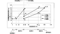
- a large capacity compressor 1 and a small capacity compressor 2 having different capacities are arranged in parallel, and the hot water supply load, the large capacity compressor 1 and the small capacity compressor are arranged. 2 has the relationship shown in FIG. 2 between the two operating frequencies.
- the operating frequency range of the large capacity compressor 1 and the operating frequency range of the small capacity compressor 2 are both 30 Hz to 100 Hz.
- FIG. 2 is a diagram showing the relationship between the hot water supply load of the heat pump hot water supply apparatus according to Embodiment 1 of the present invention and the operating frequencies of the large capacity compressor 1 and the small capacity compressor 2.
- A1 to A3 indicate points at which the operating frequency changes in the large capacity compressor 1
- B1 to B5 indicate points at which the operating frequency changes in the small capacity compressor 2.
- FIG. 2 The relationship of FIG. 2 is stored in advance in the control device 12 in the form of an arithmetic expression or a conversion table, and when the control device 12 determines the operating frequencies of the large capacity compressor 1 and the small capacity compressor 2 according to the hot water supply load. Used for.
- the numerical value (%) and the operating frequency for classifying the hot water supply load are merely examples, and these may be set as appropriate according to the actual use conditions and the like.
- the hot water supply load is “high load” (second set load (for example, 82%) or more and 100% or less) and “loading” (third set load (for example, 35%, for example) or more). The operation is different depending on when the load is less than the second set load.
- the control device 12 sets the operation frequency of the large capacity compressor 1 as the maximum operating frequency in use.
- the small capacity compressor 2 has a relationship of lowering the operation frequency as the hot water supply load is smaller, and the control device 12 determines the operation frequency of the small capacity compressor 2 according to the hot water supply load based on this relationship. To do.
- the lower limit value of the operating frequency of the large capacity compressor 1 when the hot water supply load is “high load” is an operation in which the same refrigerant circulation amount as that when the small capacity compressor 2 has the maximum operating frequency of 100 Hz is obtained.
- the frequency is 66 Hz.
- the operation frequencies of the large capacity compressor 1 and the small capacity compressor 2 are both set to be lower as the hot water supply load is smaller.
- the control device 12 determines the operating frequencies of the large capacity compressor 1 and the small capacity compressor 2 based on this relationship.
- the operating frequencies of the large-capacity compressor 1 and the small-capacity compressor 2 at this time are set so that the mutual refrigerant circulation amounts of the large-capacity compressor 1 and the small-capacity compressor 2 are the same.
- Refrigerating machine oil circulating through the large-capacity compressor 1 and the small-capacity compressor 2 can be made the same amount by controlling the respective operating frequencies so that the amounts are the same. Thereby, failure of the large capacity compressor 1 and the small capacity compressor 2 due to oil depletion can be prevented.
- the isolated operation differs depending on whether the hot water supply load is “low load” (hot water supply load 12% or more and less than 35%) and “minimum load” (hot water supply load 0% or more and less than 12%).
- the operation frequency of the small capacity compressor 2 is set to be lower as the hot water supply load is smaller. Based on this relationship, the control device 12 determines the operating frequency of the small capacity compressor 2 according to the hot water supply load.
- the control device 12 fixes the operating frequency of the small capacity compressor 2 to the minimum operating frequency for use, and starts and stops the small capacity compressor 2 according to the hot water load. .
- the hot water supply load decreases so as to cross over 35% of the hot water supply load, which is the boundary between the simultaneous operation and the single operation
- the following operation is performed. That is, when the hot water supply load decreases so as to straddle the hot water supply load 35%, the large capacity compressor 1 is stopped and switched to the single operation by the small capacity compressor 2.
- the small capacity compressor 2 so that the refrigerant circulation amount by the large capacity compressor 1 immediately before stopping the operation of the large capacity compressor 1 can be covered by one of the small capacity compressors 2 after switching to the single operation. Increase the operating frequency.
- the refrigerant circulation amounts of the large capacity compressor 1 and the small capacity compressor 2 are the same as described above. . Therefore, when the operation is switched from the simultaneous operation to the single operation, the small-capacity compressor 2 has a refrigerant circulation amount twice as large as its own refrigerant circulation amount at the time of the simultaneous operation immediately before switching to the single operation. The operating frequency will be increased.
- FIG. 3 is a flowchart of compressor operation frequency control of the heat pump water heater in Embodiment 1 of the present invention.
- the control of FIG. 6 is performed at preset control intervals.
- the control device 12 calculates the current capacity calculated from the inlet water temperature detected by the inlet water temperature detection sensor 9e and the outlet water temperature detected by the outlet water temperature detection sensor 9f, and the inlet water temperature when the current capacity is operated for a certain period of time.
- a hot water supply load is calculated based on the change (S1).
- the control apparatus 12 determines each operating frequency of the large capacity compressor 1 and the small capacity compressor 2 based on the relationship of FIG. 2 according to the calculated hot water supply load, and changes to the determined operating frequency. (S2).
- the operation of the heat pump hot water supply device 13 will be described with a specific example. This will be described with reference to the example of FIG.
- the hot water supply load is 50%
- the case where the bath hot water filling is finished and only the dishwashing is performed, and the hot water supply load is reduced to 20% is considered.
- simultaneous operation is performed when the hot water supply load is 50%, that is, the large capacity compressor 1 is operated at 40 Hz from FIG. 2, and the small capacity compressor 2 is operated at 60 Hz.
- the hot water supply load fell to 20%, in order to switch to the independent operation by the small capacity compressor 2, the large capacity compressor 1 is stopped.
- the operation frequency of the large-capacity compressor 1 is not changed from 40 Hz to 0 Hz, but at a predetermined frequency every preset control interval (for example, every 30 seconds). (For example, 10 Hz), and after reaching the lowest operating frequency of 30 Hz for use of the large capacity compressor 1, the large capacity compressor 1 is stopped at 0 Hz.
- the small capacity compressor 2 is first operating at 60 Hz when the hot water supply load is 50%.
- the operation frequency is finally lowered to 45 Hz.
- the operating frequency is decreased from 60 Hz by a predetermined frequency (for example, 10 Hz) at every control interval (for example, every 30 seconds) as described above.
- the control is once increased to 90 Hz, and then controlled to decrease again by a predetermined frequency every control interval until it reaches 45 Hz.
- the case where the hot water supply load is reduced is described as an example. However, when the hot water supply load is increased, each of the large capacity compressor 1 and the small capacity compressor 2 is performed according to FIG. The operating frequency increases.
- the large-capacity compressor 1 and the small-capacity compressor 2 having different capacities are provided in parallel, and when the load is small, the small-capacity compressor 2 can be operated independently. Since the small-capacity compressor 2 is started and stopped only when the load is smaller than “minimum load”, the number of times of starting and stopping can be reduced as compared with the conventional heat pump hot water supply apparatus. That is, since the conventional heat pump hot water supply apparatus has a configuration including two compressors having the same capacity, for example, assuming a configuration including two medium capacity compressors, if the hot water supply load is small, one medium capacity The compressor will be operated independently. On the other hand, in this Embodiment 1, since it respond
- the number of times the compressor starts and stops when the hot water supply load is small is the same as in the first embodiment.
- both of them are small capacity compressors with a small capacity, the capacity becomes insufficient for a large hot water supply load, and it becomes difficult to cope with a wide range of hot water supply loads.
- a plurality of compressors having different capacities are provided in parallel, so that the compressor can be started and stopped even when the hot water supply load is small while being able to handle a wide range of hot water supply loads.
- the heat pump hot water supply apparatus 13 that can suppress a decrease in efficiency due to start / stop can be configured.
- each compressor is determined based on the horsepower of the heat pump hot water supply device 13. Whether or not the hot water supply load of 100% can be processed when operating at the maximum operating frequency in use is a selection criterion. Then, among the various compressors that satisfy the selection criteria, a compressor that can be used in an operating frequency band with good compressor efficiency is selected in the "loading" hot water supply load region. That is, in general, in the compressor, since the operating frequency at which the compressor efficiency is maximized is determined according to the specification, the compressor is selected using this relationship.
- FIG. 4 is a characteristic diagram showing the relationship between the refrigerant circulation rate and the compressor efficiency of the heat pump hot water supply apparatus according to Embodiment 1 of the present invention.
- FIG. 4 shows the characteristics of the large capacity compressor 1 and the small capacity compressor 2. Note that A1 to A3 in FIG. 4 indicate the relationship between the refrigerant circulation amount and the compressor efficiency of the large capacity compressor 1 at the operating frequencies of A1 to A3 in FIG. Similarly, B1 to B5 in FIG. 4 show the relationship between the refrigerant circulation amount and the compressor efficiency of the small capacity compressor 2 at the respective operating frequencies B1 to B5 in FIG.
- the portion where the compressor efficiency is maximized in the characteristics of the large-capacity compressor 1 and the small-capacity compressor 2 is located in the “loading” region, which is a hot water supply load region that is frequently used. Yes.
- the capacity ratio between the large capacity compressor 1 and the small capacity compressor 2 is preferably 3: 2, and the reason will be described with reference to FIG.
- the amount of refrigerant circulation required to obtain the ability to cope with the “loading” load is roughly determined by the horsepower of the heat pump water heater 13, and here, the refrigerant circulation amount of each of the compressors 1 and 2 is determined. 260 to 600 kg / h is necessary.
- the refrigerant circulation rate of each compressor 1 and 2 is in the range of 260 to 600 kg / h, and the portion where the compressor efficiency of each compressor 1 and 2 is maximum is 1 ⁇ 4 from the lower limit and the upper limit of the simultaneous operation range. If it is located approximately on the inside, a portion with good compressor efficiency can be used in a wide range, and therefore, the capacity ratio between the large capacity compressor 1 and the small capacity compressor 2 is preferably 3: 2, as shown in FIG.
- the capacity ratio between the large capacity compressor 1 and the small capacity compressor 2 is changed to 3: 1 while leaving the large capacity compressor 1 as it is, the characteristics of the small capacity compressor 2 are in the position indicated by the dotted line in FIG. Will move.
- the small-capacity compressor 2 is used in the range where the compressor efficiency falls to the right in the hot water supply load region of “under load”, and compared with the case where the volume ratio is 3: 2. Efficiency in a hot water supply load region with a large amount decreases.
- the capacity ratio between the large capacity compressor 1 and the small capacity compressor 2 is preferably 3: 2.
- the operating frequency ranges of the large capacity compressor 1 and the small capacity compressor 2 are 30 Hz to 100 Hz.
- the “simultaneous operation range including the refrigerant circulation amount” is 30 Hz to 66 Hz for the large capacity compressor 1 and 45 Hz to 100 Hz for the small capacity compressor 2.
- a compressor with an operating frequency of 60 Hz that maximizes the compressor efficiency is selected. Thereby, there exists an effect which can use a part with sufficient compressor efficiency in a wide range.
- the first embodiment since a plurality of compressors having different capacities are connected in parallel in the refrigerant circuit, the following effects can be obtained. That is, it is possible to cope with a wide range of hot water supply loads, and even when the hot water supply load is small, the start and stop of the compressor can be reduced, and a decrease in operating efficiency due to the start and stop can be suppressed.
- the operation frequency is controlled so that the refrigerant circulation amount of each of the compressors 1 and 2 is the same in the hot water supply load region of “loading” with the highest occurrence frequency during operation,
- the refrigerating machine oil circulating through 1 and 2 can be made the same amount, and the compressor failure due to oil exhaustion can be prevented.
- the capacity ratio between the large capacity compressor 1 and the small capacity compressor 2 is set to 3: 2.
- both compressors have a good balance of compressor efficiency, including where the compressor efficiency is maximized for each of the large capacity compressor 1 and the small capacity compressor 2. 1, 2 can be used. For this reason, the average compressor efficiency in the hot water supply load region with the highest occurrence frequency during operation can be made substantially constant with high efficiency.
- the number of compressors is two here, three or more may be used.
- the hot water supply load is equal to or higher than the first set load set in advance
- the plurality of compressors are operated simultaneously, and the respective operating frequencies are controlled according to the hot water supply load.
- the compressor having the smallest capacity among the plurality of compressors may be operated independently, and the operation frequency may be controlled according to the hot water supply load.
- Embodiment 2 The heat pump hot water supply device 13 has a protection function for preventing the condensation pressure from exceeding the pressure resistance of the equipment constituting the refrigerant circuit.
- the protection function is activated when the condensing pressure exceeds a design pressure set to a value smaller than the pressure resistance, and stops the operation of the compressor. Since the operation efficiency is reduced when the compressor is frequently started and stopped by such a protection function, the second embodiment is configured to suppress frequent operation of the protection function.
- the control device 12 of the heat pump hot water supply device 13 has a reference change rate when changing the operation frequency, and specifically, preset at every control interval (for example, 30 seconds).
- the operation frequency is changed at a predetermined frequency (for example, 10 Hz).
- the control apparatus 12 changes the change rate of an operating frequency automatically according to the outside temperature measured with the heat-medium temperature detection sensor 9g so that a protective function may not occur frequently.
- FIG. 5 is a characteristic diagram showing the relationship between the air temperature and the operating frequency change rate of the heat pump water heater in Embodiment 2 of the present invention.
- the condensation pressure is 3.5 MPa or more and the outside air temperature measured by the heat medium temperature detection sensor 9g is ⁇ 15 ° C.
- the operating frequency change rate is half of the reference. Further, when the outside air temperature is 7 ° C., the operating frequency change rate is 1.5 times the standard. In addition, when the outside air temperature is 40 ° C., the operation frequency change rate is used as a reference.
- the outside air temperature is in the range of ⁇ 15 ° C. or higher and lower than 7 ° C.
- the operating frequency change rate increases, and in the range of 7 ° C. or higher and lower than 40 ° C., the operating frequency change rate decreases. Yes.
- the relationship shown in FIG. 5 is obtained by experiments or simulations in advance for the purpose of setting the current operating frequency to the operating frequency corresponding to the hot water supply load after the change at an optimum speed in order to avoid the operation of the protection function due to the high pressure increase. It is what was done.
- the relationship shown in FIG. 5 is stored in the control device 12 in the form of an arithmetic expression or a conversion table in advance, and after determining the respective operating frequencies of the large capacity compressor 1 and the small capacity compressor 2 according to the hot water supply load, When the operating frequency is changed to the determined operating frequency, the operating frequency change rate shown in FIG. 5 is used.
- the opening degree of the pressure reducing device 4 is the same, and the heat pump hot water supply device 13 has a reference change rate set in advance, and specifically, a predetermined opening that is set in advance at every control interval (for example, 30 seconds).
- the opening degree of the decompression device 4 is changed at a degree.
- the control apparatus 12 changes the opening degree change rate of the decompression device 4 automatically according to a condensation pressure so that a protective function may not occur frequently.
- the opening degree change rate is used as a reference. For example, it is changed to 80%.
- the percentage of the change rate of the opening is set to an optimum value selected in advance by simulation so that the degree of superheat can be quickly set to the set superheat degree while avoiding the activation of the protection function.
- coolant is used and the design pressure is 4.0 Mpa. Then, the refrigerant and water flows in the heat source side heat exchanger 5 are made to face each other, and while maintaining the condensation temperature of 61 ° C. (condensation pressure of 4.0 MPa or less), the amount of superheat of the discharged refrigerant (here) Then, 4 ° C.) is used, and 65 ° C. hot water is discharged without increasing the condensation temperature.
- the reason why the condensing pressure is 4.0 MPa or less is that many refrigerant circuit parts and pipes are shared with the air conditioner by reducing the cost by setting the same design pressure as that of the air conditioner.
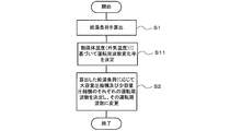
- FIG. 6 is a flowchart of compressor operating frequency control of the heat pump water heater in Embodiment 2 of the present invention.
- the same processing numbers as those in FIG. The control in FIG. 6 is performed at every control interval.
- the control device 12 calculates the hot water supply load (S1), and controls the operating frequencies of the large capacity compressor 1 and the small capacity compressor 2 according to the calculation result (S2).
- S1 hot water supply load
- S2 calculation result
- control device 12 determines the operating frequency change rate prior to the process of step S2 based on the outside air temperature measured by the heat medium temperature detection sensor 9g and FIG. 7 (S11). Then, the operation of step S2 is performed at the determined operating frequency change rate.
- FIG. 7 is a flowchart of decompression device 4 opening degree control of the heat pump hot-water supply device according to Embodiment 2 of the present invention.
- the control in FIG. 7 is performed at every control interval.
- the control of FIG. 7 is performed by the control device 12 in parallel with the control of FIG.
- the control device 12 detects the discharge refrigerant pressure by the discharge pressure sensor 10 (S21), and checks whether the detected discharge refrigerant pressure is equal to or higher than the set discharge refrigerant pressure (S22).
- the control device 12 sets the opening degree change rate to 80% of the reference (S23), and when the detected discharge refrigerant pressure is less than the set discharge refrigerant pressure, the control device 12 opens.
- the rate change rate is set to the reference itself (S24).
- the control apparatus 12 changes the opening degree of the decompression device 4 by the opening degree change rate set by step S23 or S24 so that a superheat degree may become a setting superheat degree (S25).
- FIG. 8 is a diagram showing a change in high pressure (condensation pressure) when the target hot water temperature is changed in the heat pump hot water supply apparatus according to Embodiment 2 of the present invention.
- the compressor operating frequency and the decompression device 4 are controlled under the reference conditions, and the control of the second embodiment ( FIG. 8 shows the case where “optimization control” is performed.
- the high pressure (condensation pressure) fluctuates greatly when controlled under the standard conditions. In the control of form 2, it is possible to keep the fluctuation of the high pressure (condensation pressure) small.
- the compressor operating frequency change rate is changed according to the heat medium temperature (outside air temperature), and the decompression device 4 The rate of change in opening was changed according to the discharge refrigerant pressure.
- the stable high temperature 65 degreeC hot water can be implement
- the heat pump hot water supply device 13 using the R410A refrigerant is described as being capable of high efficiency and high temperature hot water supply, but it can also be used for the heat pump hot water supply device 13 using R32 or CO 2 as the refrigerant. Needless to say.
- the outside air has been described as the heat medium for exchanging heat with the refrigerant.
- the heat medium is not limited to air but may be water, brine, or the like. The same effect can be obtained regardless of which heat medium is used.
Landscapes
- Engineering & Computer Science (AREA)
- Physics & Mathematics (AREA)
- Thermal Sciences (AREA)
- Chemical & Material Sciences (AREA)
- Combustion & Propulsion (AREA)
- Mechanical Engineering (AREA)
- General Engineering & Computer Science (AREA)
- Heat-Pump Type And Storage Water Heaters (AREA)
Abstract
Priority Applications (3)
| Application Number | Priority Date | Filing Date | Title |
|---|---|---|---|
| EP13899755.6A EP3086053B1 (fr) | 2013-12-16 | 2013-12-16 | Dispositif d'apport d'eau chaude de pompe à chaleur |
| JP2015553245A JP5985077B2 (ja) | 2013-12-16 | 2013-12-16 | ヒートポンプ給湯装置 |
| PCT/JP2013/083570 WO2015092845A1 (fr) | 2013-12-16 | 2013-12-16 | Dispositif d'apport d'eau chaude de pompe à chaleur |
Applications Claiming Priority (1)
| Application Number | Priority Date | Filing Date | Title |
|---|---|---|---|
| PCT/JP2013/083570 WO2015092845A1 (fr) | 2013-12-16 | 2013-12-16 | Dispositif d'apport d'eau chaude de pompe à chaleur |
Publications (1)
| Publication Number | Publication Date |
|---|---|
| WO2015092845A1 true WO2015092845A1 (fr) | 2015-06-25 |
Family
ID=53402241
Family Applications (1)
| Application Number | Title | Priority Date | Filing Date |
|---|---|---|---|
| PCT/JP2013/083570 WO2015092845A1 (fr) | 2013-12-16 | 2013-12-16 | Dispositif d'apport d'eau chaude de pompe à chaleur |
Country Status (3)
| Country | Link |
|---|---|
| EP (1) | EP3086053B1 (fr) |
| JP (1) | JP5985077B2 (fr) |
| WO (1) | WO2015092845A1 (fr) |
Cited By (4)
| Publication number | Priority date | Publication date | Assignee | Title |
|---|---|---|---|---|
| US10801767B2 (en) * | 2016-09-06 | 2020-10-13 | Mitsubishi Electric Corporation | Refrigeration cycle apparatus |
| CN114383324A (zh) * | 2021-12-28 | 2022-04-22 | 北京华源泰盟节能设备有限公司 | 一种冷剂泵的控制方法、装置及溴化锂吸收式大温差机组 |
| CN114593475A (zh) * | 2020-12-04 | 2022-06-07 | 青岛海尔空调电子有限公司 | 用于冷水机组的控制方法 |
| CN114593475B (zh) * | 2020-12-04 | 2024-06-07 | 青岛海尔空调电子有限公司 | 用于冷水机组的控制方法 |
Families Citing this family (1)
| Publication number | Priority date | Publication date | Assignee | Title |
|---|---|---|---|---|
| CN114484935B (zh) * | 2021-12-31 | 2023-09-26 | 青岛海尔空调电子有限公司 | 热泵机组及其控制方法和控制装置 |
Citations (7)
| Publication number | Priority date | Publication date | Assignee | Title |
|---|---|---|---|---|
| JPH0416875B2 (fr) | 1982-08-28 | 1992-03-25 | Sony Corp | |
| JP2004156849A (ja) * | 2002-11-07 | 2004-06-03 | Matsushita Electric Ind Co Ltd | ヒートポンプ給湯装置 |
| JP2007040567A (ja) * | 2005-08-01 | 2007-02-15 | Daikin Ind Ltd | 冷凍装置 |
| JP2007093100A (ja) * | 2005-09-28 | 2007-04-12 | Mitsubishi Electric Corp | ヒートポンプ給湯機の制御方法及びヒートポンプ給湯機 |
| JP2009186121A (ja) * | 2008-02-07 | 2009-08-20 | Mitsubishi Electric Corp | ヒートポンプ式給湯用室外機及びヒートポンプ式給湯装置 |
| JP2011117721A (ja) * | 2011-02-09 | 2011-06-16 | Sanyo Electric Co Ltd | ヒートポンプ式給湯装置 |
| JP2012032091A (ja) * | 2010-07-30 | 2012-02-16 | Fujitsu General Ltd | ヒートポンプサイクル装置 |
Family Cites Families (5)
| Publication number | Priority date | Publication date | Assignee | Title |
|---|---|---|---|---|
| US4523435A (en) * | 1983-12-19 | 1985-06-18 | Carrier Corporation | Method and apparatus for controlling a refrigerant expansion valve in a refrigeration system |
| JPH01244246A (ja) * | 1988-03-26 | 1989-09-28 | Mitsubishi Electric Corp | 冷凍装置 |
| US6321549B1 (en) * | 2000-04-14 | 2001-11-27 | Carrier Corporation | Electronic expansion valve control system |
| JP4016875B2 (ja) * | 2003-04-16 | 2007-12-05 | 松下電器産業株式会社 | ヒートポンプ給湯装置 |
| DE102005044029B3 (de) * | 2005-09-14 | 2007-03-22 | Stiebel Eltron Gmbh & Co. Kg | Wärmepumpe |
-
2013
- 2013-12-16 WO PCT/JP2013/083570 patent/WO2015092845A1/fr active Application Filing
- 2013-12-16 EP EP13899755.6A patent/EP3086053B1/fr active Active
- 2013-12-16 JP JP2015553245A patent/JP5985077B2/ja active Active
Patent Citations (7)
| Publication number | Priority date | Publication date | Assignee | Title |
|---|---|---|---|---|
| JPH0416875B2 (fr) | 1982-08-28 | 1992-03-25 | Sony Corp | |
| JP2004156849A (ja) * | 2002-11-07 | 2004-06-03 | Matsushita Electric Ind Co Ltd | ヒートポンプ給湯装置 |
| JP2007040567A (ja) * | 2005-08-01 | 2007-02-15 | Daikin Ind Ltd | 冷凍装置 |
| JP2007093100A (ja) * | 2005-09-28 | 2007-04-12 | Mitsubishi Electric Corp | ヒートポンプ給湯機の制御方法及びヒートポンプ給湯機 |
| JP2009186121A (ja) * | 2008-02-07 | 2009-08-20 | Mitsubishi Electric Corp | ヒートポンプ式給湯用室外機及びヒートポンプ式給湯装置 |
| JP2012032091A (ja) * | 2010-07-30 | 2012-02-16 | Fujitsu General Ltd | ヒートポンプサイクル装置 |
| JP2011117721A (ja) * | 2011-02-09 | 2011-06-16 | Sanyo Electric Co Ltd | ヒートポンプ式給湯装置 |
Non-Patent Citations (1)
| Title |
|---|
| See also references of EP3086053A4 |
Cited By (4)
| Publication number | Priority date | Publication date | Assignee | Title |
|---|---|---|---|---|
| US10801767B2 (en) * | 2016-09-06 | 2020-10-13 | Mitsubishi Electric Corporation | Refrigeration cycle apparatus |
| CN114593475A (zh) * | 2020-12-04 | 2022-06-07 | 青岛海尔空调电子有限公司 | 用于冷水机组的控制方法 |
| CN114593475B (zh) * | 2020-12-04 | 2024-06-07 | 青岛海尔空调电子有限公司 | 用于冷水机组的控制方法 |
| CN114383324A (zh) * | 2021-12-28 | 2022-04-22 | 北京华源泰盟节能设备有限公司 | 一种冷剂泵的控制方法、装置及溴化锂吸收式大温差机组 |
Also Published As
| Publication number | Publication date |
|---|---|
| EP3086053A4 (fr) | 2017-09-13 |
| JPWO2015092845A1 (ja) | 2017-03-16 |
| JP5985077B2 (ja) | 2016-09-06 |
| EP3086053A1 (fr) | 2016-10-26 |
| EP3086053B1 (fr) | 2018-06-06 |
Similar Documents
| Publication | Publication Date | Title |
|---|---|---|
| US9644876B2 (en) | Refrigeration cycle apparatus | |
| JP5818734B2 (ja) | 空気調和機 | |
| US10030894B2 (en) | Air-conditioning apparatus | |
| JP6327558B2 (ja) | 空気調和装置 | |
| KR20030097179A (ko) | 공기조화기의 압축기 동작방법 | |
| JPWO2011010473A1 (ja) | ヒートポンプ装置 | |
| JP2011069570A (ja) | ヒートポンプサイクル装置 | |
| JP5375919B2 (ja) | ヒートポンプ | |
| CN108700357A (zh) | 制冷装置 | |
| JP5985077B2 (ja) | ヒートポンプ給湯装置 | |
| JPWO2019224945A1 (ja) | 冷凍サイクル装置 | |
| JP6422590B2 (ja) | 熱源システム | |
| JP2004251535A (ja) | 空気調和機 | |
| JP2011052873A (ja) | ヒートポンプサイクル装置 | |
| JP6020162B2 (ja) | 空気調和装置 | |
| JP4730318B2 (ja) | 冷凍装置 | |
| JP6052493B2 (ja) | ヒートポンプサイクル装置 | |
| JP2005098530A (ja) | ヒートポンプ給湯装置 | |
| JPWO2015132951A1 (ja) | 冷凍装置 | |
| JP6584127B2 (ja) | 空気調和機 | |
| JP6881424B2 (ja) | 冷凍装置 | |
| JP2013092369A5 (fr) | ||
| CN104864633B (zh) | 空调系统的均油控制方法 | |
| JP2005300008A (ja) | ヒートポンプ給湯装置 | |
| KR20040000001A (ko) | 공기조화기의 난방 사이클 및 그 동작방법 |
Legal Events
| Date | Code | Title | Description |
|---|---|---|---|
| 121 | Ep: the epo has been informed by wipo that ep was designated in this application |
Ref document number: 13899755 Country of ref document: EP Kind code of ref document: A1 |
|
| ENP | Entry into the national phase |
Ref document number: 2015553245 Country of ref document: JP Kind code of ref document: A |
|
| NENP | Non-entry into the national phase |
Ref country code: DE |
|
| REEP | Request for entry into the european phase |
Ref document number: 2013899755 Country of ref document: EP |
|
| WWE | Wipo information: entry into national phase |
Ref document number: 2013899755 Country of ref document: EP |