WO2015087899A1 - 塗布部材および塗布装置 - Google Patents
塗布部材および塗布装置 Download PDFInfo
- Publication number
- WO2015087899A1 WO2015087899A1 PCT/JP2014/082637 JP2014082637W WO2015087899A1 WO 2015087899 A1 WO2015087899 A1 WO 2015087899A1 JP 2014082637 W JP2014082637 W JP 2014082637W WO 2015087899 A1 WO2015087899 A1 WO 2015087899A1
- Authority
- WO
- WIPO (PCT)
- Prior art keywords
- application needle
- application
- coating
- housing
- holder
- Prior art date
- Legal status (The legal status is an assumption and is not a legal conclusion. Google has not performed a legal analysis and makes no representation as to the accuracy of the status listed.)
- Ceased
Links
Images

Classifications
-
- H—ELECTRICITY
- H05—ELECTRIC TECHNIQUES NOT OTHERWISE PROVIDED FOR
- H05K—PRINTED CIRCUITS; CASINGS OR CONSTRUCTIONAL DETAILS OF ELECTRIC APPARATUS; MANUFACTURE OF ASSEMBLAGES OF ELECTRICAL COMPONENTS
- H05K3/00—Apparatus or processes for manufacturing printed circuits
- H05K3/10—Apparatus or processes for manufacturing printed circuits in which conductive material is applied to the insulating support in such a manner as to form the desired conductive pattern
- H05K3/12—Apparatus or processes for manufacturing printed circuits in which conductive material is applied to the insulating support in such a manner as to form the desired conductive pattern using thick film techniques, e.g. printing techniques to apply the conductive material or similar techniques for applying conductive paste or ink patterns
- H05K3/1241—Apparatus or processes for manufacturing printed circuits in which conductive material is applied to the insulating support in such a manner as to form the desired conductive pattern using thick film techniques, e.g. printing techniques to apply the conductive material or similar techniques for applying conductive paste or ink patterns by ink-jet printing or drawing by dispensing
- H05K3/125—Apparatus or processes for manufacturing printed circuits in which conductive material is applied to the insulating support in such a manner as to form the desired conductive pattern using thick film techniques, e.g. printing techniques to apply the conductive material or similar techniques for applying conductive paste or ink patterns by ink-jet printing or drawing by dispensing by ink-jet printing
-
- B—PERFORMING OPERATIONS; TRANSPORTING
- B05—SPRAYING OR ATOMISING IN GENERAL; APPLYING FLUENT MATERIALS TO SURFACES, IN GENERAL
- B05C—APPARATUS FOR APPLYING FLUENT MATERIALS TO SURFACES, IN GENERAL
- B05C1/00—Apparatus in which liquid or other fluent material is applied to the surface of the work by contact with a member carrying the liquid or other fluent material, e.g. a porous member loaded with a liquid to be applied as a coating
- B05C1/02—Apparatus in which liquid or other fluent material is applied to the surface of the work by contact with a member carrying the liquid or other fluent material, e.g. a porous member loaded with a liquid to be applied as a coating for applying liquid or other fluent material to separate articles
- B05C1/027—Apparatus in which liquid or other fluent material is applied to the surface of the work by contact with a member carrying the liquid or other fluent material, e.g. a porous member loaded with a liquid to be applied as a coating for applying liquid or other fluent material to separate articles only at particular parts of the articles
-
- B—PERFORMING OPERATIONS; TRANSPORTING
- B05—SPRAYING OR ATOMISING IN GENERAL; APPLYING FLUENT MATERIALS TO SURFACES, IN GENERAL
- B05C—APPARATUS FOR APPLYING FLUENT MATERIALS TO SURFACES, IN GENERAL
- B05C1/00—Apparatus in which liquid or other fluent material is applied to the surface of the work by contact with a member carrying the liquid or other fluent material, e.g. a porous member loaded with a liquid to be applied as a coating
- B05C1/02—Apparatus in which liquid or other fluent material is applied to the surface of the work by contact with a member carrying the liquid or other fluent material, e.g. a porous member loaded with a liquid to be applied as a coating for applying liquid or other fluent material to separate articles
-
- B—PERFORMING OPERATIONS; TRANSPORTING
- B05—SPRAYING OR ATOMISING IN GENERAL; APPLYING FLUENT MATERIALS TO SURFACES, IN GENERAL
- B05C—APPARATUS FOR APPLYING FLUENT MATERIALS TO SURFACES, IN GENERAL
- B05C1/00—Apparatus in which liquid or other fluent material is applied to the surface of the work by contact with a member carrying the liquid or other fluent material, e.g. a porous member loaded with a liquid to be applied as a coating
- B05C1/04—Apparatus in which liquid or other fluent material is applied to the surface of the work by contact with a member carrying the liquid or other fluent material, e.g. a porous member loaded with a liquid to be applied as a coating for applying liquid or other fluent material to work of indefinite length
- B05C1/06—Apparatus in which liquid or other fluent material is applied to the surface of the work by contact with a member carrying the liquid or other fluent material, e.g. a porous member loaded with a liquid to be applied as a coating for applying liquid or other fluent material to work of indefinite length by rubbing contact, e.g. by brushes, by pads
-
- H—ELECTRICITY
- H05—ELECTRIC TECHNIQUES NOT OTHERWISE PROVIDED FOR
- H05K—PRINTED CIRCUITS; CASINGS OR CONSTRUCTIONAL DETAILS OF ELECTRIC APPARATUS; MANUFACTURE OF ASSEMBLAGES OF ELECTRICAL COMPONENTS
- H05K2203/00—Indexing scheme relating to apparatus or processes for manufacturing printed circuits covered by H05K3/00
- H05K2203/01—Tools for processing; Objects used during processing
- H05K2203/0104—Tools for processing; Objects used during processing for patterning or coating
- H05K2203/013—Inkjet printing, e.g. for printing insulating material or resist
Definitions
- the present invention relates to an application member and an application device, and more particularly to an application member and an application device for applying liquid material droplets to a material to be processed using an application needle.
- Japanese Patent Application Laid-Open No. 2007-268353 As a method for finely applying a liquid material using an application needle, for example, a method using an application unit as disclosed in Japanese Patent Application Laid-Open No. 2007-268353 has been proposed.
- the coating unit disclosed in Japanese Patent Application Laid-Open No. 2007-268353 is intended to correct fine pattern defects, and can perform fine coating using a material having a wide range of viscosity.
- the application unit there is only one drive shaft of the drive unit (air cylinder) that drives the application needle, and the drive unit and the arm that fixes and supports the application needle are not fixed, and are attached to the drive shaft.
- the arm is supported by a pin protruding from the drive plate.
- the coating material is applied to the substrate by bringing the tip of the coating needle to which the coating material is adhered into contact with the surface to be coated.
- the masses of the application needle fixing plate, the arm, and the movable portion of the linear motion guide member are loaded on the tip of the application needle.
- the present invention has been made to solve the above-described problems, and a main object of the present invention is to provide an application member that can be applied at high speed using a fine application needle and an application apparatus using the same. Is to provide.
- An application member includes an application needle holder including an application needle and a base body that detachably holds the application needle holder.
- the application needle holder includes a housing, a fixing member, and a linear motion member.
- the fixing member is disposed inside the housing, and the application needle is fixed.
- the linear motion member supports the fixed member so as to be movable in one direction inside the housing.
- a coating apparatus includes the above-described coating member and a holding table that holds a processing target material to which a liquid material is coated by a coating needle.
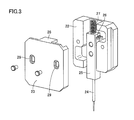
- FIG. 3 is a development view of an application needle holder in the application mechanism shown in FIG. 2. It is a schematic diagram which shows the base body in the application
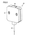
- FIG. 4 is a schematic perspective view of the application needle holder shown in FIG. 3.
- FIG. 4 is a schematic perspective view of the application needle holder shown in FIG. 3.
- a coating apparatus includes a processing chamber, a Y-axis table 2 arranged in the processing chamber, an X-axis table 1, a Z-axis table 3, and coating. It mainly includes a mechanism 4, an observation optical system 6, a CCD camera 7 connected to the observation optical system 6, and a control unit.
- the control unit includes a monitor 9, a control computer 10, and an operation panel 8.
- a Y-axis table 2 is installed on the bottom of the processing chamber.
- This Y-axis table 2 is movable in the Y-axis direction.
- a guide portion is installed on the lower surface of the Y-axis table 2.
- the guide portion is slidably connected to a guide rail installed on the bottom surface of the processing chamber.
- a ball screw is connected to the lower surface of the Y-axis table 2.
- the Y-axis table 2 can be moved along the guide rail (in the Y-axis direction).
- the upper surface of the Y-axis table 2 is a mounting surface on which the substrate 5 that is a processing target material is mounted.
- the X-axis table 1 is installed on the Y-axis table 2.
- the X-axis table 1 is disposed on a structure that is installed so as to straddle the Y-axis table 2 in the X-axis direction.
- a moving body connected to the Z-axis table 3 is installed so as to be movable in the X-axis direction.
- the moving body is movable in the X-axis direction using, for example, a ball screw.
- the X-axis table 1 is fixed to the bottom surface of the processing chamber via the structure. Therefore, the Y-axis table 2 described above is movable in the Y-axis direction with respect to the X-axis table 1.
- the moving body connected to the X-axis table 1 is provided with the Z-axis table 3 as described above.
- An observation optical system 6 and a coating mechanism 4 are connected to the Z-axis table 3.
- the observation optical system 6 is for observing the application position of the substrate 5 to be applied.
- the CCD camera converts the observed image into an electrical signal.
- the Z-axis table 3 holds the observation optical system 6 and the coating mechanism 4 so as to be movable in the Z-axis direction.
- a control computer 10 and an operation panel 8 for controlling these Y-axis table 2, X-axis table 1, Z-axis table 3, observation optical system 6 and coating mechanism 4, and a monitor 9 attached to the control computer are: It is installed outside the processing chamber.
- the monitor 9 displays image data converted by the CCD camera 7 and output data from the control computer 10.
- the operation panel 8 is used for inputting a command to the control computer 10.
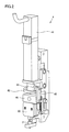
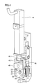
- the coating mechanism 4 includes a servo motor 41, a cam 43, a bearing 44 held in contact with the cam surface of the cam 43, a cam connecting plate 45, a movable portion 46, and a coating.
- a movable base 35 (see FIG. 4) for holding the needle holder 20 and an application material container 21 (see FIG. 2) are mainly included.
- the application needle holder 20 is detachable from the movable base 35.
- the servo motor 41 is installed such that the central axis extends in the direction along the Z-axis direction shown in FIG.
- a cam 43 is connected to the rotation shaft of the servo motor 41.
- the cam 43 is rotatable about the central axis of the servo motor 41.
- the cam 43 includes a center portion connected to the rotation shaft of the servo motor 41 and a flange portion connected to one end portion of the center portion.
- the upper surface of the flange portion (surface on the servo motor 41 side) is a cam surface.
- the cam surface is formed in an annular shape along the outer periphery of the center portion, and is formed in a slope shape so that the distance from the bottom surface of the flange portion varies.
- the cam surface has a farthest (thick) upper end flat region that is the farthest from the bottom surface, a lower end flat region that is spaced from the upper end flat region, and the upper end flat region. And a slope portion that smoothly connects the lower end flat region.
- the lower end flat region is a region where the distance from the bottom surface is the shortest (thin thickness).
- the bearing 44 is arranged so as to be in contact with the cam surface of the cam 43.
- a cam coupling plate 45 is connected to the bearing 44.
- the other end opposite to the one end connected to the bearing 44 is fixed to the movable portion 46.
- a movable base 35 is connected to the movable portion 46.
- the application needle holder 20 is installed on the movable base 35.
- the application needle holder 20 includes an application needle 24.
- the application needle 24 is arranged so as to protrude from the application needle holder 20 on the lower surface of the application needle holder 20 (the lower side opposite to the side where the servo motor 41 is located).
- a coating material container 21 is disposed under the coating needle holder 20.
- the application needle 24 is held in the application material container 21 in an inserted state.
- a fixed pin is fixed to the movable part 46. Further, the other fixing pin is fixed to the gantry holding the servo motor 41.
- a spring is installed so as to connect the fixing pins. Due to this spring, the movable portion 46 is in a state of receiving a force directed toward the coating material container 21 side. Further, the bearing 44 is kept pressed against the cam surface of the cam 43 by the force of the spring.
- the movable portion 46 and the movable base 35 are connected to a linear guide installed on a gantry holding the servo motor 41, and are movable along the Z-axis direction.
- the cam 43 is rotated by driving the servo motor 41 to rotate the rotation shaft of the servo motor 41.
- the position of the bearing 44 in contact with the cam surface of the cam 43 in the Z-axis direction varies according to the rotation of the rotation shaft of the servo motor 41.
- the position of the application needle 24 in the Z-axis direction can be changed by moving the movable portion 46 and the movable base 35 in the Z-axis direction in accordance with the position variation of the bearing 44 in the Z-axis direction.
- the application needle holder 20 mainly includes a holder base 22, an application needle fixing plate 25 to which the application needle 24 is fixed, and a holder lid 23. Inside the holder base 22, a recess is formed for accommodating the application needle fixing plate 25 to which the application needle 24 is bonded and fixed. A linear guide 26 is fixed in the recess. The linear guide 26 is arranged to define the moving direction of the application needle fixing plate 25. The application needle fixing plate 25 is held in contact with the linear guide 26.
- a spring 27 as an elastic member is connected to the other end of the application needle fixing plate 25 opposite to the one end where the application needle 24 is fixed.
- the spring 27 is disposed in a state of being sandwiched between the other end of the application needle fixing plate 25 and the spring receiver 28 in the holder lid 23.
- the application needle fixing plate 25 can be pressed to the application needle 24 side. For this reason, when the applicator needle 24 is moved up and down, the position of the applicator needle 24 can be prevented from shifting (fluctuating with respect to the holder base in the vertical direction). Further, when an excessive stress is applied to the application needle 24 when the application needle 24 comes into contact with the surface of the substrate 5 as a processing target material, the spring 27 is elastically deformed to absorb the stress.
- the value of the stress applied to the application needle 24 when the application needle 24 comes into contact with the surface of the substrate 5 is affected by the force from the spring 27, so that the force that the spring 27 applies to the application needle fixing plate 25. Is preferably adjusted to a minimum value necessary for holding the application needle 24 at a position on the substrate side.
- the holder lid 23 has a long hole 29 through which a screw used to fix the holder lid 23 to the holder base 22 is passed.
- the long hole 29 is formed to have a long axis in a direction along the direction in which the linear guide 26 extends (that is, the direction in which the application needle 24 moves) when the holder lid 23 is installed on the holder base 22. .
- the holder lid 23 can be fixed to the holder base 22 after the position of the holder lid 23 with respect to the holder base 22 is changed in the long axis direction of the long hole.
- the holder lid 23 may be fixed to the holder base 22 while measuring the force applied to the tip of the application needle 24 by the spring 27, for example.
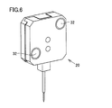
- the coating needle holder 20 is detachable from the movable base 35.
- a plurality of (two in FIG. 6) magnets 32 are arranged on the surface (the surface of the holder base 22) that faces the movable base 35.
- a plurality of (two in FIG. 4) magnets 33 are also arranged on the movable base 35.
- the position of the application needle holder 20 is adjusted when the application needle holder 20 is attracted to the movable base 35 by the magnetic force acting between the magnet 32 and the magnet 33.
- Accurate positioning For example, the reference surface 30 of the application needle holder 20 can be pressed against the reference surface 34 of the movable base 35, and the reference surface 31 of the application needle holder 20 can be pressed against the reference surface 36 of the movable base 35. .
- the position of the magnet 33 of the movable base 35 is changed from the position of the magnet 32 of the application needle holder 20 facing each other to the reference surfaces 34 and 36.
- a magnetic force between the magnets 32 and 33 can apply a suction force toward the reference surfaces 34 and 36 (attraction force in the direction indicated by the arrow in FIG. 4) with respect to the application needle holder 20. it can.
- the application needle holder 20 can be fixed to the movable base 35 with high reproducibility with high positional accuracy.
- the operation of the coating apparatus shown in FIGS. 1 to 6 will be described.
- the X-axis table 1 and the Y-axis table 2 are operated so that the drawing area on the substrate 5 to be coated is directly below the observation optical system 6. Move. Then, the drawing start position is observed and confirmed by the observation optical system 6, and the drawing start position is determined. Using the determined drawing start position as a reference, when the application needle 24 is projected, the Z-axis table 3 is operated to a position where the tip of the application needle 24 contacts the surface of the substrate 5, and the application mechanism 4 is lowered.
- the servo motor 41 is operated to cause the application needle 24 to protrude, and the liquid material adhering to the tip of the application needle 24 is brought into contact with the surface of the substrate 5.
- the substrate 5 is moved from the drawing start position using the X-axis table 1 and the Y-axis table 2 so that the position to be drawn is located immediately below the coating mechanism 4.
- the application needle 24 is projected when the movement is completed, the application mechanism 4 is lowered by the Z-axis table 3 to a position where the tip of the application needle 24 contacts the surface of the substrate 5.
- the servo motor 41 of the application mechanism 4 is driven to apply the liquid material to the substrate 5 by projecting the application needle 24.
- the substrate 5 When coating continuously, the substrate 5 is moved by the X-axis table 1 and the Y-axis table 2 so that the next drawing position is located immediately below the coating mechanism 4, and the servo motor 41 of the coating mechanism 4 is driven. Apply. By repeating this operation, a circuit pattern is drawn on the surface of the substrate 5. After all the coating is completed, the coating mechanism 4 is raised using the Z-axis table 3.
- the relationship between the lower end position of the application needle 24 and the focus position of the observation optical system 6 is stored in advance in the control unit.
- the position where the image is focused by the observation optical system 6 is used as a reference in the Z-axis direction, and the coating mechanism is applied by the Z-axis table 3 until the coating needle 24 comes into contact with the substrate 5 when the coating needle 24 is projected.
- the servo motor 41 of the application mechanism 4 is driven, and the application needle 24 is projected to perform application.
- the focus position is confirmed during the drawing operation as necessary, and the Z axis of the application needle 24 is checked. Apply after correcting the position in the direction.
- the adjustment of the focus position at this time may be a method of automatically adjusting the focus using image processing, or the height position of the surface of the substrate 5 is always detected by using a laser sensor or the like, and the focus is corrected in real time. The method of doing may be used.
- An application member (application mechanism 4) includes an application needle holder 20 including an application needle 24, and a base body that detachably holds the application needle holder 20.
- the application needle holder 20 includes a housing (holder base 22, holder lid 23), a fixing member (application needle fixing plate 25), and a linear motion member (linear guide 26).
- the fixing member (25) is disposed inside the housing (22, 23), and the application needle 24 is fixed thereto.
- the linear motion member (26) supports the fixed member (25) so as to be movable in one direction inside the housings (22, 23).
- the application needle holder 20 includes the application needle 24 and the linear movement member (26) that supports the application needle 24 so as to be movable in one direction, so that the linear movement member (26) is the application needle.
- the application member (4) can be made smaller and lighter than when it is arranged separately from the holder 20. For this reason, even when the moving speed of the application needle 24 is high when the application needle 24 is brought into contact with the surface of the processing target material (the substrate 5 that is the application target material), the load applied to the application needle 24 is reduced. It can be made smaller than before (for example, the mass of the portion supporting the application needle 24 can be reduced to about 10% of the conventional one). Therefore, the diameter of the application needle 24 can be reduced and the application speed can be increased.
- the application needle holder 20 has an elastic member (spring 27) that applies a pressing force to the fixing member (25) in the direction in which the application needle 24 protrudes from the application needle holder 20. Further, it may be included. In this case, since a certain stress can be applied to the application needle 24 by the elastic member (27), the relative movement of the application needle 24 in the application needle holder 20 when the application member (4) is moved. The fluctuation of the position can be suppressed and the position accuracy of the application needle 24 can be increased.
- the housing (22, 23) in the application needle holder 20, includes a first housing portion (holder base 22) and a second housing portion (holder lid 23). May be.
- the fixing member (25) may be connected to the first housing portion (22) via the linear motion member (26).
- the elastic member (27) may be disposed so as to contact a part of the fixing member (25) and a part of the second housing part (23) (spring receiver 28).
- the first housing portion (22) and the second housing portion (23) may be capable of changing the relative positional relationship.
- the second housing part (23) may be formed with a long hole 29 having a long axis along one direction in which the fixing member (25) can move.
- the second housing part (23) may be fixed to the first housing part (22) by a positioning member (screw) passed through the long hole 29.
- a coating apparatus includes a holding table (Y-axis table 2) that holds the coating member (4) and a processing target material (substrate 5) to which a liquid material is coated by the coating needle 24. ). In this way, it is possible to realize a coating apparatus that can perform coating at high speed using the miniaturized coating needle 24.
- the present invention provides a coating member for conducting conductive pattern drawing, correcting open defects in conductive patterns, forming fine circuit patterns such as RFID tags, correcting defects, and applying a conductive adhesive. And particularly advantageously applied to liquid material applicators.
Landscapes
- Engineering & Computer Science (AREA)
- Manufacturing & Machinery (AREA)
- Microelectronics & Electronic Packaging (AREA)
- Coating Apparatus (AREA)
Priority Applications (1)
| Application Number | Priority Date | Filing Date | Title |
|---|---|---|---|
| CN201480067690.0A CN105813765B (zh) | 2013-12-13 | 2014-12-10 | 涂布构件及涂布装置 |
Applications Claiming Priority (2)
| Application Number | Priority Date | Filing Date | Title |
|---|---|---|---|
| JP2013-258189 | 2013-12-13 | ||
| JP2013258189A JP6381902B2 (ja) | 2013-12-13 | 2013-12-13 | 塗布針ホルダ |
Publications (1)
| Publication Number | Publication Date |
|---|---|
| WO2015087899A1 true WO2015087899A1 (ja) | 2015-06-18 |
Family
ID=53371201
Family Applications (1)
| Application Number | Title | Priority Date | Filing Date |
|---|---|---|---|
| PCT/JP2014/082637 Ceased WO2015087899A1 (ja) | 2013-12-13 | 2014-12-10 | 塗布部材および塗布装置 |
Country Status (3)
| Country | Link |
|---|---|
| JP (1) | JP6381902B2 (enExample) |
| CN (1) | CN105813765B (enExample) |
| WO (1) | WO2015087899A1 (enExample) |
Cited By (2)
| Publication number | Priority date | Publication date | Assignee | Title |
|---|---|---|---|---|
| US11478813B2 (en) * | 2017-02-27 | 2022-10-25 | Ntn Corporation | Liquid application unit with application needle for applying liquid material on target, and liquid application apparatus including liquid application unit |
| WO2023072624A1 (de) * | 2021-10-28 | 2023-05-04 | Focke & Co. (Gmbh & Co. Kg) | VORRICHTUNG ZUM AUFTRAGEN VON VORZUGSWEISE ERWÄRMTEM KLEBSTOFF BZW. (HEIß-)LEIM |
Families Citing this family (5)
| Publication number | Priority date | Publication date | Assignee | Title |
|---|---|---|---|---|
| JP6835506B2 (ja) * | 2016-09-01 | 2021-02-24 | Ntn株式会社 | 液体塗布ユニットおよび液体塗布装置 |
| JP6461260B1 (ja) * | 2017-08-02 | 2019-01-30 | Ntn株式会社 | 塗布機構及び塗布装置 |
| JP7164997B2 (ja) | 2018-08-31 | 2022-11-02 | Ntn株式会社 | 塗布針部材、塗布針部材アセンブリ、塗布部材および塗布装置 |
| JP7621134B2 (ja) | 2021-02-25 | 2025-01-24 | Ntn株式会社 | 塗布機構及び塗布装置 |
| JP7681421B2 (ja) * | 2021-04-08 | 2025-05-22 | サンスター技研株式会社 | 塗工装置 |
Citations (3)
| Publication number | Priority date | Publication date | Assignee | Title |
|---|---|---|---|---|
| JPH0253162U (enExample) * | 1988-10-12 | 1990-04-17 | ||
| JP2008178775A (ja) * | 2007-01-23 | 2008-08-07 | Shibaura Mechatronics Corp | 流体塗布装置および塗布距離測定方法 |
| JP2013081884A (ja) * | 2011-10-07 | 2013-05-09 | Musashi Eng Co Ltd | 液体材料の吐出装置および方法 |
Family Cites Families (4)
| Publication number | Priority date | Publication date | Assignee | Title |
|---|---|---|---|---|
| WO1997009128A1 (fr) * | 1995-09-07 | 1997-03-13 | Nippon Steel Corporation | Procede de peinture du flanc de decoupe d'une tole d'acier pre-enduite |
| JP4125031B2 (ja) * | 2002-04-11 | 2008-07-23 | 株式会社リコー | 定着装置及びその定着装置を有する画像形成装置 |
| JP4767708B2 (ja) * | 2005-03-28 | 2011-09-07 | Ntn株式会社 | 塗布ユニットおよびパターン修正装置 |
| JP2008073637A (ja) * | 2006-09-22 | 2008-04-03 | Ntn Corp | 塗布針洗浄装置 |
-
2013
- 2013-12-13 JP JP2013258189A patent/JP6381902B2/ja active Active
-
2014
- 2014-12-10 WO PCT/JP2014/082637 patent/WO2015087899A1/ja not_active Ceased
- 2014-12-10 CN CN201480067690.0A patent/CN105813765B/zh active Active
Patent Citations (3)
| Publication number | Priority date | Publication date | Assignee | Title |
|---|---|---|---|---|
| JPH0253162U (enExample) * | 1988-10-12 | 1990-04-17 | ||
| JP2008178775A (ja) * | 2007-01-23 | 2008-08-07 | Shibaura Mechatronics Corp | 流体塗布装置および塗布距離測定方法 |
| JP2013081884A (ja) * | 2011-10-07 | 2013-05-09 | Musashi Eng Co Ltd | 液体材料の吐出装置および方法 |
Cited By (2)
| Publication number | Priority date | Publication date | Assignee | Title |
|---|---|---|---|---|
| US11478813B2 (en) * | 2017-02-27 | 2022-10-25 | Ntn Corporation | Liquid application unit with application needle for applying liquid material on target, and liquid application apparatus including liquid application unit |
| WO2023072624A1 (de) * | 2021-10-28 | 2023-05-04 | Focke & Co. (Gmbh & Co. Kg) | VORRICHTUNG ZUM AUFTRAGEN VON VORZUGSWEISE ERWÄRMTEM KLEBSTOFF BZW. (HEIß-)LEIM |
Also Published As
| Publication number | Publication date |
|---|---|
| CN105813765A (zh) | 2016-07-27 |
| CN105813765B (zh) | 2018-11-16 |
| JP2015112577A (ja) | 2015-06-22 |
| JP6381902B2 (ja) | 2018-08-29 |
Similar Documents
| Publication | Publication Date | Title |
|---|---|---|
| JP6381902B2 (ja) | 塗布針ホルダ | |
| JP6411735B2 (ja) | 塗布部材、塗布装置および塗布方法 | |
| WO2017090381A1 (ja) | 塗布ユニット、塗布装置、被塗布対象物の製造方法および基板の製造方法 | |
| CN107614122B (zh) | 液体涂布单元及液体涂布装置 | |
| WO2018155589A1 (ja) | 液体塗布ユニットおよび液体塗布装置 | |
| JP6491296B2 (ja) | 塗布部材、塗布装置および塗布方法 | |
| WO2016093007A1 (ja) | 塗布機構および塗布装置 | |
| JP6560108B2 (ja) | 塗布ユニット、塗布装置、被塗布対象物の製造方法および基板の製造方法 | |
| US10751747B2 (en) | Application mechanism, application apparatus, method for manufacturing object to which application material is applied, and method for manufacturing substrate | |
| WO2020189642A1 (ja) | キャピラリ案内装置及びワイヤボンディング装置 | |
| JP6794187B2 (ja) | 液体塗布ユニットおよび液体塗布装置 | |
| JP6716654B2 (ja) | 塗布部材、塗布装置および塗布方法 | |
| JP2017094287A (ja) | 塗布ユニット、塗布装置、被塗布対象物の製造方法および基板の製造方法 | |
| JP2024121598A (ja) | 塗布針および塗布装置 | |
| CN116847933A (zh) | 涂布机构和涂布装置 | |
| JP2018130694A (ja) | 液体塗布ユニットおよび液体塗布装置 | |
| WO2016204152A1 (ja) | 塗布装置 |
Legal Events
| Date | Code | Title | Description |
|---|---|---|---|
| 121 | Ep: the epo has been informed by wipo that ep was designated in this application |
Ref document number: 14868987 Country of ref document: EP Kind code of ref document: A1 |
|
| NENP | Non-entry into the national phase |
Ref country code: DE |
|
| 122 | Ep: pct application non-entry in european phase |
Ref document number: 14868987 Country of ref document: EP Kind code of ref document: A1 |