WO2015083344A1 - 熱輸送装置 - Google Patents
熱輸送装置 Download PDFInfo
- Publication number
- WO2015083344A1 WO2015083344A1 PCT/JP2014/005899 JP2014005899W WO2015083344A1 WO 2015083344 A1 WO2015083344 A1 WO 2015083344A1 JP 2014005899 W JP2014005899 W JP 2014005899W WO 2015083344 A1 WO2015083344 A1 WO 2015083344A1
- Authority
- WO
- WIPO (PCT)
- Prior art keywords
- heat
- composite
- conductor
- heat generating
- composite member
- Prior art date
- Legal status (The legal status is an assumption and is not a legal conclusion. Google has not performed a legal analysis and makes no representation as to the accuracy of the status listed.)
- Ceased
Links
Images




Classifications
-
- B—PERFORMING OPERATIONS; TRANSPORTING
- B60—VEHICLES IN GENERAL
- B60H—ARRANGEMENTS OF HEATING, COOLING, VENTILATING OR OTHER AIR-TREATING DEVICES SPECIALLY ADAPTED FOR PASSENGER OR GOODS SPACES OF VEHICLES
- B60H1/00—Heating, cooling or ventilating devices
- B60H1/00271—HVAC devices specially adapted for particular vehicle parts or components and being connected to the vehicle HVAC unit
-
- B—PERFORMING OPERATIONS; TRANSPORTING
- B60—VEHICLES IN GENERAL
- B60H—ARRANGEMENTS OF HEATING, COOLING, VENTILATING OR OTHER AIR-TREATING DEVICES SPECIALLY ADAPTED FOR PASSENGER OR GOODS SPACES OF VEHICLES
- B60H1/00—Heating, cooling or ventilating devices
- B60H1/00642—Control systems or circuits; Control members or indication devices for heating, cooling or ventilating devices
- B60H1/00985—Control systems or circuits characterised by display or indicating devices, e.g. voice simulators
-
- B—PERFORMING OPERATIONS; TRANSPORTING
- B60—VEHICLES IN GENERAL
- B60H—ARRANGEMENTS OF HEATING, COOLING, VENTILATING OR OTHER AIR-TREATING DEVICES SPECIALLY ADAPTED FOR PASSENGER OR GOODS SPACES OF VEHICLES
- B60H1/00—Heating, cooling or ventilating devices
- B60H1/22—Heating, cooling or ventilating devices the heat source being other than the propulsion plant
-
- B—PERFORMING OPERATIONS; TRANSPORTING
- B60—VEHICLES IN GENERAL
- B60H—ARRANGEMENTS OF HEATING, COOLING, VENTILATING OR OTHER AIR-TREATING DEVICES SPECIALLY ADAPTED FOR PASSENGER OR GOODS SPACES OF VEHICLES
- B60H1/00—Heating, cooling or ventilating devices
- B60H1/32—Cooling devices
- B60H1/3204—Cooling devices using compression
- B60H1/3227—Cooling devices using compression characterised by the arrangement or the type of heat exchanger, e.g. condenser, evaporator
-
- B—PERFORMING OPERATIONS; TRANSPORTING
- B60—VEHICLES IN GENERAL
- B60R—VEHICLES, VEHICLE FITTINGS, OR VEHICLE PARTS, NOT OTHERWISE PROVIDED FOR
- B60R16/00—Electric or fluid circuits specially adapted for vehicles and not otherwise provided for; Arrangement of elements of electric or fluid circuits specially adapted for vehicles and not otherwise provided for
- B60R16/02—Electric or fluid circuits specially adapted for vehicles and not otherwise provided for; Arrangement of elements of electric or fluid circuits specially adapted for vehicles and not otherwise provided for electric constitutive elements
-
- F—MECHANICAL ENGINEERING; LIGHTING; HEATING; WEAPONS; BLASTING
- F28—HEAT EXCHANGE IN GENERAL
- F28F—DETAILS OF HEAT-EXCHANGE AND HEAT-TRANSFER APPARATUS, OF GENERAL APPLICATION
- F28F21/00—Constructions of heat-exchange apparatus characterised by the selection of particular materials
- F28F21/02—Constructions of heat-exchange apparatus characterised by the selection of particular materials of carbon, e.g. graphite
-
- H—ELECTRICITY
- H05—ELECTRIC TECHNIQUES NOT OTHERWISE PROVIDED FOR
- H05K—PRINTED CIRCUITS; CASINGS OR CONSTRUCTIONAL DETAILS OF ELECTRIC APPARATUS; MANUFACTURE OF ASSEMBLAGES OF ELECTRICAL COMPONENTS
- H05K7/00—Constructional details common to different types of electric apparatus
- H05K7/20—Modifications to facilitate cooling, ventilating, or heating
- H05K7/2039—Modifications to facilitate cooling, ventilating, or heating characterised by the heat transfer by conduction from the heat generating element to a dissipating body
-
- H—ELECTRICITY
- H05—ELECTRIC TECHNIQUES NOT OTHERWISE PROVIDED FOR
- H05K—PRINTED CIRCUITS; CASINGS OR CONSTRUCTIONAL DETAILS OF ELECTRIC APPARATUS; MANUFACTURE OF ASSEMBLAGES OF ELECTRICAL COMPONENTS
- H05K7/00—Constructional details common to different types of electric apparatus
- H05K7/20—Modifications to facilitate cooling, ventilating, or heating
- H05K7/2039—Modifications to facilitate cooling, ventilating, or heating characterised by the heat transfer by conduction from the heat generating element to a dissipating body
- H05K7/20409—Outer radiating structures on heat dissipating housings, e.g. fins integrated with the housing
- H05K7/20418—Outer radiating structures on heat dissipating housings, e.g. fins integrated with the housing the radiating structures being additional and fastened onto the housing
-
- H—ELECTRICITY
- H10—SEMICONDUCTOR DEVICES; ELECTRIC SOLID-STATE DEVICES NOT OTHERWISE PROVIDED FOR
- H10W—GENERIC PACKAGES, INTERCONNECTIONS, CONNECTORS OR OTHER CONSTRUCTIONAL DETAILS OF DEVICES COVERED BY CLASS H10
- H10W40/00—Arrangements for thermal protection or thermal control
- H10W40/20—Arrangements for cooling
- H10W40/25—Arrangements for cooling characterised by their materials
-
- B—PERFORMING OPERATIONS; TRANSPORTING
- B60—VEHICLES IN GENERAL
- B60H—ARRANGEMENTS OF HEATING, COOLING, VENTILATING OR OTHER AIR-TREATING DEVICES SPECIALLY ADAPTED FOR PASSENGER OR GOODS SPACES OF VEHICLES
- B60H1/00—Heating, cooling or ventilating devices
- B60H1/22—Heating, cooling or ventilating devices the heat source being other than the propulsion plant
- B60H1/2215—Heating, cooling or ventilating devices the heat source being other than the propulsion plant the heat being derived from electric heaters
-
- B—PERFORMING OPERATIONS; TRANSPORTING
- B60—VEHICLES IN GENERAL
- B60H—ARRANGEMENTS OF HEATING, COOLING, VENTILATING OR OTHER AIR-TREATING DEVICES SPECIALLY ADAPTED FOR PASSENGER OR GOODS SPACES OF VEHICLES
- B60H1/00—Heating, cooling or ventilating devices
- B60H1/22—Heating, cooling or ventilating devices the heat source being other than the propulsion plant
- B60H2001/2268—Constructional features
- B60H2001/229—Integration into an air outlet
-
- F—MECHANICAL ENGINEERING; LIGHTING; HEATING; WEAPONS; BLASTING
- F28—HEAT EXCHANGE IN GENERAL
- F28F—DETAILS OF HEAT-EXCHANGE AND HEAT-TRANSFER APPARATUS, OF GENERAL APPLICATION
- F28F13/00—Arrangements for modifying heat-transfer, e.g. increasing, decreasing
- F28F2013/001—Particular heat conductive materials, e.g. superconductive elements
-
- F—MECHANICAL ENGINEERING; LIGHTING; HEATING; WEAPONS; BLASTING
- F28—HEAT EXCHANGE IN GENERAL
- F28F—DETAILS OF HEAT-EXCHANGE AND HEAT-TRANSFER APPARATUS, OF GENERAL APPLICATION
- F28F13/00—Arrangements for modifying heat-transfer, e.g. increasing, decreasing
- F28F2013/005—Thermal joints
- F28F2013/006—Heat conductive materials
-
- F—MECHANICAL ENGINEERING; LIGHTING; HEATING; WEAPONS; BLASTING
- F28—HEAT EXCHANGE IN GENERAL
- F28F—DETAILS OF HEAT-EXCHANGE AND HEAT-TRANSFER APPARATUS, OF GENERAL APPLICATION
- F28F2255/00—Heat exchanger elements made of materials having special features or resulting from particular manufacturing processes
- F28F2255/20—Heat exchanger elements made of materials having special features or resulting from particular manufacturing processes with nanostructures
Definitions
- the present disclosure is to provide a heat transport device having a heat conductor that can transfer heat between a heat generating member to be cooled and a heat radiating member that radiates heat transmitted from the heat generating member. More particularly, the present invention relates to a heat transport device that uses a vehicle air conditioner to cool an electronic device in a vehicle compartment that is the heat generating member at a position away from the vehicle air conditioner.
- Non-Patent Document 1 discloses that carbon nanotubes are added to a composite material of carbon fiber and aluminum and sintered with plasma, so that an object having a thermal conductivity three times or more that of aluminum is obtained. ing.
- Non-Patent Document 1 the vapor-grown carbon fiber (VGCF or simply referred to as the above-mentioned carbon fiber) and aluminum are present inside the composite material without being in contact with other vapor-grown carbon fibers.
- VGCF vapor-grown carbon fiber
- aluminum we focus on vapor-grown carbon fibers that do not contribute to heat conduction. Then, the vapor-grown carbon fiber and another vapor-grown carbon fiber are cross-linked with small-sized carbon nanotubes to improve the heat conduction characteristics.
- the circuit board and the heat sink are adjacent and integrated, and there are restrictions on mountability and assemblability in the vehicle, which is not preferable for cooling electronic devices dispersed in the vehicle. There is a case. In other words, even if the heat generated by the semiconductor can be efficiently transferred to the heat sink, it must be individually cooled by air cooling or the like of the heat sink, and there is a limit to cooling the semiconductor due to the cooling performance of the heat sink. .
- Non-Patent Document 1 improves the heat conduction characteristics of the composite material of vapor-grown carbon fiber, carbon nanotube, and aluminum, but there is no disclosure regarding the improvement in the mounting property and assembling property in the vehicle. .
- An object of the present disclosure is to provide a heat transport device that has good heat transfer characteristics between a heat generating member to be cooled and a heat radiating member, and can easily connect the heat generating member and the heat radiating member with a flexible heat conductor. There is to do.
- the heat transport device includes a heat generating member that generates heat, a heat radiating member that radiates heat, and flexibility, and the heat generating member and the heat radiating member are thermally connected to each other.
- a composite member that exchanges heat with at least one of the heat generating member and the heat radiating member.
- the composite member includes a base material that exchanges heat with at least one of the heat generating member and the heat radiating member, and a plurality of carbon nanotubes and a plurality of carbon fibers mixed in the base material.
- a plurality of carbon fibers are cross-linked by a plurality of carbon nanotubes.
- the end portion of the heat conductor is cross-linked via a plurality of carbon fibers in the composite member and a plurality of carbon nanotubes.
- At least one of one end and the other end of the flexible heat conductor is embedded in the composite member. At least one of the embedded one end and the other end is cross-linked by the carbon fiber and the carbon nanotube in the composite member. Therefore, heat transfer between the heat conductor and the composite member is good. Therefore, it is possible to provide a heat transport device that can improve the heat transfer characteristics between the heat generating member and the heat radiating member and can easily connect the heat generating member and the heat radiating member with a flexible heat conductor.
- the heat conductor may include a carbon fiber cable having a group of carbon fibers or a sheet-like graphite that is a carbon-based polymer material.
- one end of the flexible heat conductor is embedded in the composite member, and one end of the embedded heat conductor is cross-linked via the carbon fiber and the carbon nanotube in the composite member.
- The may have a carbon fiber cable or sheet-like graphite which is the same carbon-based material.
- the composite member may be composed of a heat generation side composite member and a heat dissipation side composite member.
- the heat generation side composite member may exchange heat with the heat generation member, and the heat dissipation side composite member may exchange heat with the heat dissipation member.
- the heat generation side composite member and the heat dissipation side composite member may be connected by a heat conductor.
- the composite member has a heat generation side composite member provided on one side of the heat conductor and a heat dissipation side composite member provided on the other side of the heat conductor. Therefore, one end of the heat conductor is embedded in the heat generating side composite member. And the other end of a heat conductor is embedded in the thermal radiation side composite member. And since the embedded heat conductor is bridge
- a fixing member constituting the connector may be coupled to the heat generating member or the heat radiating member by a claw portion or a screw.
- the heat transport device may further include an elastic member housed in the fixing member.
- the elastic member may be compressed in a state where the fixing member is coupled, and the base member may be directly or indirectly pressed against the surface of the heat generating member or the surface of the heat radiating member. According to this, in addition to the press contact by the claw portion or the screw, the base material can be further pressed into contact with the heat generating member or the heat radiating member by the elastic force of the elastic member, and heat transfer is improved.
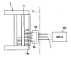
- FIG. 1 shows a heat transport device 100 according to the first embodiment of the present disclosure.
- FIG. 2 shows a partial side view of the heat transport device 100 as seen in the direction of arrow II in FIG.
- FIG. 3 is a schematic configuration near the instrument panel of the vehicle to which the heat transport device 100 is attached.
- the heat generating member 1 that generates heat is a semiconductor element in the head-up display 310 that becomes the electronic device 3 in the vehicle interior.
- the heat dissipating member 2 that radiates heat is an evaporator 5 in the vehicle air conditioner 4.
- the evaporator 5 constitutes a single heat radiating member 2 for a plurality of heat generating members 1.
- the other of the heat generating members 1 is a semiconductor element in the navigation device 320 of FIG. 3 provided inside the instrument panel. These semiconductor elements are mounted on the circuit board 16 via connection bumps.
- the one side composite member 6a heat generation side composite member
- the other side composite member 6b heat dissipation side composite member
- the composite member 6, composite member 6a, composite member 6b are provided between the heat generating member 1 and the heat radiating member 2.
- a plurality of heat conductors 71 and 72 also simply referred to as heat conductor 7.
- the heat from the plurality of heat generating members 1 is transmitted to the single heat radiating member 2.
- the plurality of composite members 6 are mounted in the navigation device 320 and the head-up display 310 which are the heat generating members 1 (1a and 1b).
- FIG. 3 illustrates the heat conductor 7 (71, 72) of the heat transport device 100 attached in front of the driver seat and the passenger seat in the vehicle.
- the set of heat conductors 71 is connected to the evaporator 5 and the head-up display 310 in the air conditioning case of the vehicle air conditioner 4.
- the other set of heat conductors 72 is connected to the evaporator 5 and the navigation device 320.
- the head-up display 310 and the navigation device 320 are mounted in front of the driver's seat in the vehicle interior.
- An air conditioning duct of the vehicle air conditioner 4 and an evaporator 5 in the air conditioning duct are also mounted in front of the driver's seat.
- the heat transport device 100 connects the composite member 6 a (FIG. 1) on the heat generating member 1 side and the composite member 6 b on the heat radiating member 2 side to transfer heat from the heat generating member 1 to the heat radiating member 2.
- the conductor 7 (71, 72) is provided.
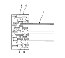
- FIG. 4 schematically shows the internal structure of the composite member 6.
- the composite member 6 is described in Non-Patent Document 1, and is configured by combining a carbon nanotube 9 and a carbon fiber 10 with a metal containing aluminum (or copper) as a base material 8.
- the carbon fiber 10 and the carbon fiber 10 in the composite member 6 are cross-linked by carbon nanotubes 9.
- the base material 8 exchanges heat with the heat generating member 1 or the heat radiating member 2.
- Cross section hatching of the composite member 6 in FIG. 4 is omitted.
- a carbon nanotube is a substance in which carbon atoms are connected like a network to form a cylinder and has a diameter of several nanometers. It has high strength, elastic modulus and flexibility, and has excellent electrical and thermal conductivity.
- the heat conductor 7 has a flexible length of about 50 cm, and one end (end portion) thereof is composed of a carbon fiber cable composed of a carbon fiber group embedded in the composite member 6. Since one end of the heat conductor 7 is embedded in the composite member 6, the heat conductor 7 is cross-linked via the carbon fibers 10 and the carbon nanotubes 9 in the composite member 6.
- the heat conductor 7 is a linear structure extending from one to the other.
- the material of the heat conductor 7 is an aggregate (carbon fiber group) of carbon fibers which are carbon-based materials, and commercially available products can be used.
- the heat conductor 7 only needs to have a length connecting the heat generating member 1 and the heat radiating member 2 in the vehicle, and a length of 15 cm to 150 cm is used.
- the heat conductor 7 thermally connects the heat generating member 1 and the heat radiating member 2, and transmits heat generated by the heat generating member 1 to the heat radiating member 2.
- the composite member 6 is attached to the heat generating member 1 and the heat radiating member 2 by a fixing member 12 that forms a connector as shown in FIG. Thereby, the composite member 6 is directly or indirectly pressed against the surface of the heat generating member 1 and the surface of the heat radiating member 2.
- the navigation device 320 In the vehicle instrument panel, the navigation device 320, the head-up display 310, an LED (light emitting diode) (not shown), etc. generate heat and become hot in the summer. For this reason, failure or proper operation will not occur unless heat dissipation (cooling) is performed. Therefore, generally, a heat sink, a heat radiating fin, a blower, a heat pipe, and the like are required.
- the heat generating member 1 and the heat radiating member 2 are rigid and thermal such as a heat pipe. If it is connected to, it is difficult to assemble.
- the heat conductor 7 is a linear structure extending from one flexible to the other, the assembly is easy. In addition, quietness can be maintained without fan noise.
- FIG. 4 is an explanatory view showing a coupling structure of the composite member 6 and the heat conductor 7 by removing the fixing member 12 made of synthetic resin.
- the composite member 6 is configured by combining a carbon (9) and carbon fiber (10) with a metal (or synthetic resin) as a base material (8), and the carbon fiber (10) and the carbon fiber (10) in the base material (8) are carbon nanotubes. 9 is cross-linked.
- the other end of the heat conductor 7 that is not shown is connected to a semiconductor element that serves as the heat generating member 1.
- One end of the heat conductor 7 is partially embedded in the composite member 6.
- the heat conductor 7 has a length of about 50 cm and is configured by bundling millions of flexible carbon fibers (linear carbon).
- the composite member 6 is made of aluminum (or copper) as a base material 8 and mixed with 50% carbon fiber 10 and 0.5% carbon nanotube 9 in volume content and sintered by plasma.
- the mixed carbon fiber 10 has a length of about 300 ⁇ m and a diameter of 7 ⁇ m.
- One end of the heat conductor 7 is partially embedded in the composite member 6 as shown in FIG. 4, but since the length of the carbon fiber 10 is approximately 300 ⁇ m, it is more than 5 times this 300 ⁇ m ( It is preferably embedded with a length of preferably 10 times or more.
- the semiconductor element 1a serving as the heat generating member 1 and the composite member 6a are thermally connected by the interface material 13 (13a, 13b).
- the interface material 13 corrects unevenness of the surface roughness of the composite member 6 and the semiconductor element 1a to reduce thermal resistance, and is a thin elastic rubber or grease mixed with carbon nanotubes and carbon fibers. It consists of The interface material 13 is not essential.
- the vehicle air conditioner 4 has an evaporator 5 made of an aluminum alloy in an air conditioning duct.
- the evaporator 5 is cooled by evaporating the refrigerant constituting the refrigeration cycle of the vehicle air conditioner 4 inside.
- the fixing member 12 is attached to the resin member or the metal member on which the semiconductor element 1a or the like is mounted by the claw portions 14 (14a, 14b).
- the claw portion 14 and the fixing member 12 are integrated with synthetic resin or the like. It is a molded product.
- the fixing member 12 has the claw portion 14 and can be fixed to the circuit board 16 made of a resin member or a heat sink made of a metal member with one touch, and can be prevented from coming off.
- the vicinity of the refrigerant inflow portion where the refrigerant flows or the portion where the liquid refrigerant is low and the temperature is low tends to absorb heat.
- the heat transport device 100 transmits heat from the heat generating member 1 to the heat radiating member 2 by connecting the heat generating member 1 and the heat radiating member 2.
- the heat transport device 100 includes a composite member 6 and a heat conductor 7.
- the composite member 6 is configured by combining a plurality of carbon nanotubes 9 and a plurality of carbon fibers 10 mixed in the base material 8, and the carbon fibers 10 and the carbon fibers 10 are cross-linked by the carbon nanotubes 9.
- the heat conductor 7 has one flexible end embedded in the composite member 6, and the embedded one end and the carbon fiber 10 in the composite member 6 are cross-linked via the carbon nanotubes 9.
- the heat conductor 7 has one end of the flexible heat conductor 7 embedded in the composite member 6.
- the embedded one end is cross-linked by the carbon fiber 10 and the carbon nanotube 9 in the composite member 6. Therefore, heat transfer between the heat conductor 7 and the composite member 6 is good. Accordingly, it is possible to provide a heat transport device 100 that has good heat transfer characteristics between the heat generating member 1 and the heat radiating member 2 and can easily connect the heat generating member 1 and the heat radiating member 2 with a flexible heat conductor 7. Can do.
- the heat conductor 7 is composed of a carbon fiber cable that is a carbon-based material. Therefore, one end of the flexible heat conductor 7 is embedded in the composite member 6. One end of the embedded heat conductor 7 is cross-linked through the carbon fiber 10 and the carbon nanotube 9 in the composite member 6. In order to crosslink with the carbon fiber 10 in the composite member 6 and obtain good heat transfer characteristics, a carbon fiber cable which is the same carbon-based material is preferable.
- the base material 8 of the composite member 6 contains aluminum or copper. Therefore, since aluminum or copper is used as the base material 8 constituted by combining the carbon nanotubes 9 and the carbon fibers 10, and the carbon fibers 10 and the carbon fibers 10 are cross-linked by the carbon nanotubes 9, the thermal conductivity is good. It is.
- the composite member 6 has a composite member 6 a on one side provided on one side of the heat conductor 7 and a composite member 6 b on the other side provided on the other side of the heat conductor 7. Then, one end of one side of the heat conductor 7 is embedded in one composite member 6a, and the other end of the heat conductor 7 is embedded in the other composite member 6b.
- the composite member 6 since the composite member 6 has the composite member 6a on one side provided on one side of the heat conductor 7 and the composite member 6b on the other side provided on the other side of the heat conductor 7, the composite member 6 has flexibility. One end of the heat conductor 7 having a gap is embedded in the composite member 6a on the one side. And the one end of the other side of the heat conductor 7 is embedded in the other side composite member 6b. And since the embedded heat conductor 7 is bridge
- the composite member 6 is attached to the heat generating member 1 or the heat radiating member 2 by the fixing member 12, and the base member 8 is directly or directly to the surface of the heat generating member 1 or the surface of the heat radiating member 2. It is indirectly pressed. According to this, heat transfer between the heat conductor 7 and the heat generating member 1 or the heat radiating member 2 is good.
- the fixing member 12 is a connector having a claw portion 14 in which the composite member 6 is accommodated and the heat conductor 7 is led out from the surface of the fixing member 12 and coupled to the heat generating member 1 or the heat radiating member 2. It is configured. Therefore, the heat conductor 7 can be easily attached to the heat generating member 1 or the heat radiating member 2.
- the heat generating member 1 is constituted by an electronic device 3 in the vehicle
- the heat radiating member 2 is constituted by an evaporator 5 of a vehicle air conditioner 4 in the vehicle. Accordingly, the cold heat of the evaporator 5 cooled by the refrigerant is transmitted to the electronic device 3, and the electronic device 3 can be cooled.
- a single heat radiating member 2 is provided for a plurality of heat generating members 1, and each of the heat generating members 1 and the heat radiating member 2 are connected by a plurality of composite members 6 and a plurality of heat conductors 7.
- the heat from the plurality of heat generating members 1 is transmitted to the single heat radiating member 2. That is, the heat conductor 7 can concentrate and dissipate heat from the plurality of heat generating members 1 on the single heat radiating member 2.
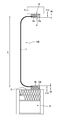
- FIG. 5 shows a schematic configuration of a heat transport device according to the second embodiment of the present disclosure.
- the evaporator 5 of the vehicle air conditioner constitutes a heat radiating member 2 with respect to the heat generating member 1.
- the heat generating member 1 is, for example, a semiconductor element in the head-up display 310 (FIG. 3 described in the first embodiment) provided inside the instrument panel.
- the heat generating member 1 and the heat radiating member 2 are connected by the composite member 6 (6a, 6b) and the heat conductor 7, and the heat from the heat generating member 1 is transmitted to the heat radiating member 2.
- the heat generating member 1 may be a semiconductor element in the navigation device 320.
- the navigation device 320 is mounted in front of the driver's seat in the vehicle compartment.
- An air conditioning duct of the vehicle air conditioner 4 and an evaporator 5 in the air conditioning duct are also mounted in front of the driver's seat.
- the composite member 6 is configured by combining carbon nanotubes and carbon fibers using a metal as a base material.
- the carbon fiber and carbon fiber in this composite member are cross-linked by carbon nanotubes.
- the base material in the composite member 6 contacts the heat generating member 1 and the heat radiating member 2 via the interface material 13 (13a, 13b), and contains aluminum or copper.
- the composite member 6 has a thickness t6 of 10 mm, and the interface material 13 has a thickness t13 of 1 mm.
- the heat conductor 7 is made of a material having a flexible length L of about 50 cm and one end embedded in the composite member 6 (6a, 6b). By embedding this one end, the heat conductor 7 is cross-linked through the carbon fiber and the carbon nanotube in the composite member 6.
- the heat conductor 7 is a linear structure extending from one to the other.
- the material of the heat conductor is a carbon fiber cable that is a carbon-based material.
- the composite member 6 is attached to the heat generating member 1 and the heat radiating member 2. Thereby, the base material 8 is directly or indirectly pressed against the surface of the heat generating member 1 and the surface of the heat radiating member 2. Since the heat conductor 7 is a linear structure extending from one flexible to the other, it is easy to assemble.
- the composite member 6 (6a, 6b) is configured by combining the carbon nanotube 9 and the carbon fiber 10 with aluminum or copper as the base material 8, and the carbon fiber 10 They are cross-linked by carbon nanotubes 9.
- the composite member 6 is obtained by sintering aluminum or copper as a base material 8 and mixing the base material 8 with 50% of carbon fiber 10 and 0.5% of carbon nanotubes 9 by volume and sintering with plasma. is there.
- the mixed carbon fiber has a length of approximately 300 ⁇ m and a diameter of 7 ⁇ m.
- the interface material 13 corrects unevenness of the surface roughness between the composite member 6 and the semiconductor element, and reduces thermal resistance.
- the interface material 13 is made of thin elastic rubber mixed with carbon nanotubes and carbon fibers, or grease.
- FIG. 6 shows the characteristic value of each part of the second embodiment shown in FIG. 5 and the amount of heat transfer based on the characteristic value.
- the thermal conductivity ⁇ 6 of the composite member 6 is about 1000 W / mK at maximum (unit: watt / meter ⁇ Kelvin).
- the flexible thermal conductor 7 combined with the composite member 6 has a considerably low thermal resistance and a thermal conductivity equal to or higher than that of the composite member 6.
- the cross-sectional area A7 of the heat conductor 7 is 38.5 square mm.
- the heat conductor 7 is composed of a bundle of carbon fibers, and the heat in the heat conductor 7 is well transmitted in the connecting direction of the carbon atoms, so it is necessary to insulate the periphery of the heat conductor 7. Absent.
- the surface temperature Ti of the semiconductor element of the electronic device such as the navigation device 320 is 85 ° C. (corresponding to the guaranteed upper limit temperature of the electronic device), and the surface temperature To of the evaporator 5 is 5 ° C.
- the cross section of the composite member 6 is a rectangle having two pairs of sides facing each other, and the heat conductor 7 conducts heat conduction from one side (short side) of the shorter set of the two sets of sides.
- One end of the body 7 is embedded in the composite member 6.
- the carbon fiber cable comprised from the carbon fiber group which comprises the heat conductor 7 is unraveled and branched into plurality.
- the heat transport device 100 connects the heat generating member 1 and the heat radiating member 2 to transmit heat from the heat generating member 1 to the heat radiating member 2.
- the heat transport device 100 includes a composite member 6 and a heat conductor 7.
- the composite member 6 is configured by combining a plurality of carbon nanotubes 9 and a plurality of carbon fibers 10 mixed in the base material 8, and the carbon fibers 10 and the carbon fibers 10 are cross-linked by the carbon nanotubes 9.
- the heat conductor 7 is flexible and has one end embedded in the composite member 6. The embedded one end and the carbon fiber 10 in the composite member 6 are cross-linked through the carbon nanotube 9.
- one end of the flexible heat conductor 7 is embedded in the composite member 6, and the embedded one end is the carbon fiber 10 and the carbon nanotube 9 in the composite member 6.
- the embedded one end is the carbon fiber 10 and the carbon nanotube 9 in the composite member 6.
- heat transfer between the heat conductor 7 and the composite member 6 is good. Accordingly, it is possible to provide a heat transport device 100 that has good heat transfer characteristics between the heat generating member 1 and the heat radiating member 2 and can easily connect the heat generating member 1 and the heat radiating member 2 with a flexible heat conductor 7. Can do.
- the heat conductor 7 is composed of a carbon fiber cable that is a carbon-based material. One end of the flexible heat conductor 7 is embedded in the composite member 6. One end of the embedded heat conductor 7 is cross-linked through the carbon fiber 10 and the carbon nanotube 9 in the composite member 6. In order to crosslink with the carbon fiber 10 in the composite member 6 and obtain good heat transfer characteristics, a carbon fiber cable which is the same carbon-based material is preferable.
- the base material 8 of the composite member 6 contains aluminum or copper. Therefore, the thermal conductivity is good.
- the composite member 6 includes a composite member 6 a on one side provided on one side of the heat conductor 7 and a composite member 6 b on the other side provided on the other side of the heat conductor 7. One end of one side of the heat conductor 7 is embedded in the one-side composite member 6a, and the other end of the heat conductor 7 is embedded in the other-side composite member 6b.
- the composite member 6 since the composite member 6 has the composite member 6a on one side provided on one side of the heat conductor 7 and the composite member 6b on the other side provided on the other side of the heat conductor 7, it is flexible. One end of the conductive heat conductor 7 is embedded in the composite member 6a on one side. And the one end of the other side of the heat conductor 7 is embedded in the other side composite member 6b. And since the embedded heat conductor 7 is bridge
- the composite member 6 has a rectangular cross section, and one end of the heat conductor 7 is embedded in the composite member 6 from the shorter side of the opposing sides of the rectangle. Therefore, the embedding depth can be increased.
- the heat conductor 7 includes a plurality of carbon fiber groups
- the carbon fiber cable is broken in the composite member 6 and is branched into a plurality. By branching in this way, the carbon fiber cable serving as the heat conductor 7 and the carbon fiber 10 of the composite member 6 are more complicatedly cross-linked via the carbon nanotubes 9, and the heat transfer performance is improved.
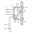
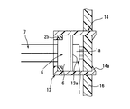
- FIG. 7 illustrates a schematic configuration of a connector on the electronic device side according to the third embodiment of the present disclosure.
- the fixing member 12 constituting the outer shell of the connector accommodates the composite member 6 therein, and the heat conductor 7 is led out from the surface of the fixing member 12.
- a claw portion 14 coupled to the circuit board 16 of the semiconductor element 1 a constituting the heat generating member 1 is provided on the fixing member 12.
- the fixing member 12 is coupled to the circuit board 16 by the claw portion 14, and the composite member 6 having the base material 8 is pressed against the surface of the semiconductor element 1 a constituting the heat generating member 1 through the interface material 13.
- an electric heating element (for example, PTC) 23 that generates heat when energized from the battery 22 by turning on the switch 21 is provided inside the fixing member 12.
- the electric heating element 23 When the temperature is low, the electric heating element 23 is energized to control the heat generating member 1 composed of the semiconductor element 1a of the electronic device within a predetermined temperature range.
- the electric heating element 23 can also be used as a space heater, and serves to prevent dew condensation that is harmful to the electronic device because the temperature in the fixing member 12 constituting the outer shell of the connector is lowered.
- a heat radiating member 2 instead of the heat generating member 1, may be provided.
- the fixing member 12 may be attached with a screw instead of the claw portion 14. Further, a heat sink may be provided instead of the circuit board 16.
- the composite member 6 is attached to the heat generating member 1 or the heat radiating member 2 by the fixing member 12, and the base material 8 is attached to the surface of the heat generating member 1 or the surface of the heat radiating member 2. It is pressed directly or indirectly. According to this, heat transfer between the heat conductor 7 and the heat generating member 1 or the heat radiating member 2 is good.
- the fixing member 12 has the claw portion in which the composite member 6 is accommodated in the closed space, the heat conductor 7 is led out from the surface of the fixing member 12, and is coupled to the heat generating member 1 or the heat radiating member 2. It is configured as a connector having a fastener consisting of 14 (or screws). Therefore, the heat conductor 7 can be easily attached to the heat generating member 1 or the heat radiating member 2.
- the heat generating member 1 is constituted by an electronic device 3 in the vehicle
- the heat radiating member 2 is constituted by an evaporator 5 of a vehicle air conditioner 4 in the vehicle. Therefore, the cold heat of the evaporator 5 cooled by the refrigerant is transmitted to the electronic device 3 so that the electronic device 3 can be cooled.
- FIG. 8 shows a schematic configuration of a connector according to the fourth embodiment of the present disclosure.
- the fixing member 12 accommodates the composite member 6 therein, and the heat conductor 7 is led out from the surface of the fixing member 12.
- a fixing member 12 is configured as an outer shell of a connector having a claw portion 14 coupled to the heat generating member 1.
- the composite member 6 is pressed into contact with the surface of the heat generating member 1 by the claw portion 14 via the interface material 13a.
- a screw may be used instead of the claw portion 14.
- a ring-shaped elastic member 25 is provided in the fixing member 12.
- the elastic member 25 is compressed, and the elastic member 25 tries to return to its original state.
- the composite member 6 is pressed against the surface of the heat generating member 1 directly or indirectly by elastic force.
- the elastic member 25 or the like can also be used when the composite member is pressed against the surface of the heat radiating member 2.
- the elastic member may be composed of a metal spring in addition to the ring-shaped rubber.
- the composite member 6 is attached to the heat generating member 1 or the heat radiating member 2 by the fixing member 12, and the composite member 6 is attached to the surface of the heat generating member 1 or the surface of the heat radiating member 2. Directly or indirectly. According to this, heat transfer between the heat conductor 7 and the heat generating member 1 or the heat radiating member 2 is good.
- the fixing member 12 accommodates the composite member 6 therein, the heat conductor 7 is led out from the surface of the fixing member 12, and a claw portion 14 or a screw that is coupled to the heat generating member 1 or the heat radiating member 2. It is configured as a connector having a fastener. Therefore, the heat conductor 7 can be easily attached to the heat generating member 1 or the heat radiating member 2.
- the composite member 6 is compressed directly or indirectly with respect to the surface of the heat generating member 1 or the surface of the heat radiating member 2 by being compressed in a state where the connector is coupled to the heat generating member 1 or the heat radiating member 2 by the claw portion 14 or the screw.
- An elastic member 25 that is in pressure contact is provided in the fixing member 12. Therefore, in addition to the press contact by the claw portion 14 or the screw, the elastic member 25 can be pressed more reliably by the elasticity of the elastic member 25, and the heat transfer is improved.
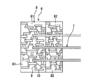
- FIG. 9 shows a coupling structure of the composite member 6 (61, 62) and the heat conductor 7 by removing the fixing member 12 made of synthetic resin in the connector.
- the composite member 6 includes a first composite part 61 and a second composite part 62.
- the first composite portion 61 is configured by combining the carbon nanotube 9 and the carbon fiber 10 with the metal as the first base material 81, and the carbon fiber 10 and the carbon fiber 10 are cross-linked by the carbon nanotube 9.
- the second composite portion 62 that is in close contact with the first composite portion 61 is configured by combining the carbon nanotube 9 and the carbon fiber 10 with a synthetic resin or rubber as the second base material 82.
- the carbon fibers 10 and the carbon fibers 10 in the second base material 82 made of synthetic resin or rubber are cross-linked by the carbon nanotubes 9.
- the other end (the right side in FIG. 9) of the heat conductor 7 is connected to a semiconductor element serving as the heat generating member 1.
- One end of the heat conductor 7 is partially embedded in the first composite portion 61 and penetrates through the second composite portion 62.
- the heat conductor 7 has a length of about 50 cm and is configured by bundling millions of flexible carbon fibers. In addition, you may use the sheet-like graphite mentioned later instead of a carbon fiber cable.
- the heat transport device 100 connects the heat generating member 1 and the heat radiating member 2 to transmit heat from the heat generating member 1 to the heat radiating member 2.
- the heat transport device 100 includes a composite member 6 and a heat conductor 7.
- the composite member 6 is configured by combining a plurality of carbon nanotubes 9 and a plurality of carbon fibers 10 mixed in the base material 8 (81, 82), and the carbon fibers 10 and the carbon fibers 10 are formed by the carbon nanotubes 9. It is cross-linked.
- One end of the heat conductor 7 having flexibility is embedded in the composite member 6, and the embedded one end and the carbon fiber 10 in the composite member 6 are cross-linked via the carbon nanotube 9.
- the heat conductor 7 has one end of the flexible heat conductor 7 embedded in the composite member 6. Since the embedded one end is cross-linked by the carbon fiber 10 and the carbon nanotube 9 in the composite member 6, heat transfer between the heat conductor 7 and the composite member 6 is good. Therefore, it is possible to provide a heat transport device that has good heat transfer characteristics between the heat generating member 1 and the heat radiating member 2 and can easily connect the heat generating member 1 and the heat radiating member 2 with a flexible heat conductor 7. it can.
- the heat conductor 7 is made of a carbon fiber cable or a sheet-like graphite which is a carbon-based material.
- One end of the flexible heat conductor 7 is embedded in the composite member 6.
- One end of the embedded heat conductor 7 is cross-linked through the carbon fiber 10 and the carbon nanotube 9 in the composite member 6.
- a carbon fiber cable or sheet-like graphite which is the same carbon-based material is preferable.
- the composite member 6 has a first composite part 61 and a second composite part 62 adjacent to the first composite part 61.
- the substrate 8 has a first substrate 81 in the first composite portion 61 and a second substrate 82 in the second composite portion 62.
- the first base member 81 includes aluminum or copper, is directly or indirectly pressed against the heat generating member 1 or the heat radiating member 2, and one end of the heat conductor 7 is embedded therein.
- the second base material 82 comes into contact with the first base material 81 and the heat conductor 7 penetrates, and includes a synthetic resin or rubber.
- the first base member 81 of the base member 8 includes aluminum or copper and is directly or indirectly pressed against the heat generating member 1 or the heat radiating member 2. And the 2nd base material 82 is contacting the 1st base material 81 among the base materials 8, and the heat conductor 7 penetrates, and contains a synthetic resin or rubber
- the first composite portion 61 of the composite member 6 in which the carbon fiber 10 and the carbon fiber 10 are cross-linked by the carbon nanotubes 9 contains aluminum or copper.
- the second composite portion 62 including the second base material 82 made of a synthetic resin or rubber through which the heat conductor 7 penetrates and the carbon fiber 10 is cross-linked through the carbon nanotubes 9 like the first composite portion 61.
- the mechanical stress applied to the heat conductor 7 by the synthetic resin or rubber of the second composite portion 62 can be relaxed, and disconnection of the heat conductor 7 can be suppressed.
- the heat generating member 1 is configured by an electronic device 3 in the vehicle
- the heat radiating member 2 is configured by an evaporator 5 of a vehicle air conditioner 4 in the vehicle. Therefore, the cold heat of the evaporator 5 cooled by the refrigerant is transmitted to the electronic device 3 so that the electronic device 3 can be cooled.
- the second base material 82 including the synthetic resin or rubber of the second composite portion 62 mechanical stress due to vehicle vibration applied to the heat conductor 7 is relieved, and disconnection of the heat conductor 7 can be suppressed.
- the evaporator 5 of the vehicle air conditioner constitutes a single heat radiating member for the plurality of heat generating members.
- the heating member is a semiconductor element in a head-up display provided inside the instrument panel, a semiconductor element in a navigation device, a lighting control device for a headlamp, or the like.
- the heat generating member and the heat radiating member are connected by a plurality of heat conductors 71, 72, 73, and heat from the plurality of heat generating members is transmitted to the evaporator 5 which is a single heat radiating member.
- a connector having a plurality of fixing members 12a1, 12a2, and 12a3 has a composite member therein.
- the fixing members 12a1 to 12a3 are mounted in a navigation device, a head-up display, and a lighting control device that are heat generating members.
- the head-up display, the navigation device, and the lighting control device are mounted in front of the driver's seat in the vehicle interior.
- An air conditioning duct of the vehicle air conditioner and the evaporator 5 in the air conditioning duct are also mounted in front of the driver's seat. Accordingly, the heat conductors 71 to 73 need only be relatively short.
- the heat conductors 71 to 73 connect the plurality of composite members on the heat generating member side and the single composite member on the heat dissipating member side, and transmit heat from the heat generating member to the heat dissipating member.
- the composite member is attached to the heat generating member and the heat radiating member by fixing members 12a1 to 12a3 that form a connector and are made of synthetic resin.
- the fixing members 12a1 to 12a3 are shaped so that the composite members in the respective fixing members 12a1 to 12a3 are directly or indirectly pressed against the heat generating member 1 and attached to a circuit board, a heat sink or the like. It is an integrally molded product.
- the fixing members 12a1 to 12a3 have claw portions 14 or screws 15 (15a and 15b), and are structured to be fixed to a circuit board or a heat sink.
- the fixing member 12b which is a coupling portion between the evaporator 5 and the composite member, is attached to the portion where the liquid refrigerant is accumulated with a screw 15b.
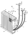
- the evaporator 5 is arranged such that a plurality of tubes 27 made of aluminum or aluminum alloy having a flat cross section are arranged in a direction substantially perpendicular to the flow of an arrow Y10 of air that is a heat exchange fluid.
- a fin 28 is interposed between the tubes 27, and a core 29 is formed by the tubes 27 and the fins 28. Both side surfaces of the core 29 are covered with side plates 30.
- the fixing member 12b is attached to the side plate 30 made of aluminum or aluminum alloy with screws 15b.
- An upper tank portion 31 is disposed above the tube 27, and a lower tank portion 32 is disposed below the tube 27.
- the refrigerant introduced from the refrigerant inlet 33 a of the connection portion 33 flows up or down in the tube 27 and flows out of the refrigerant outlet 33 b of the connection portion 33.
- the heat transport device 100 connects the heat generating member and the heat radiating member to transmit heat from the heat generating member to the heat radiating member.
- the heat transport device 100 includes a composite member and a heat conductor 7.
- the composite member is configured by combining a plurality of carbon nanotubes and a plurality of carbon fibers mixed in the base material, and the carbon fibers and the carbon fibers are cross-linked by the carbon nanotubes.
- the heat conductor 7 has a flexible end embedded in the composite member 6.
- the embedded one end and the carbon fiber in the composite member 6 are cross-linked by carbon nanotubes.
- the heat conductor 7 is a carbon fiber cable or sheet-like graphite extending from one to the other.
- the embedded one end is cross-linked to the carbon fiber and the carbon nanotube in the composite member 6. Therefore, heat transfer between the heat conductor 7 and the composite member 6 is good. Therefore, it is possible to provide a heat transport device that has good heat transfer characteristics between the heat generating member and the heat radiating member and can easily connect the heat generating member and the heat radiating member with the flexible heat conductor 7.
- the heat conductor 7 is composed of a carbon fiber cable that is a carbon-based material. Then, one end of the embedded heat conductor 7 is cross-linked through the carbon fiber and the carbon nanotube in the composite member. In order to crosslink with the carbon fiber in the composite member 6 and obtain good heat transfer characteristics, carbon fiber or sheet-like graphite which is the same carbon-based material is preferable.
- the heat generating member is constituted by three different electronic devices in the vehicle, and the heat radiating member is constituted by an evaporator 5 which is a heat exchanger of the vehicle air conditioner in the vehicle. Therefore, the cold heat of the evaporator 5 cooled by the refrigerant is transmitted to the electronic device or the like, and the electronic device or the like can be cooled.
- FIG. 11 shows a schematic configuration of the connector on the other side according to the seventh embodiment of the present disclosure.
- the heat conductor 7 uses a sheet-like graphite obtained by pyrolyzing a polymer film and graphitizing it.
- Such sheet-like graphite is commercially available and is made by a method of graphitizing a polymer film by thermal decomposition.
- Such sheet-like graphite is highly oriented graphite having a structure close to a single crystal, and has high thermal conductivity and flexibility.
- the heat transport device 100 connects the heat generating member and the heat radiating member to transmit heat from the heat generating member to the heat radiating member.
- the heat transport device 100 includes a composite member 6 and a heat conductor 7.
- the composite member 6 is configured by combining a plurality of carbon nanotubes and a plurality of carbon fibers mixed in a base material, and the carbon fibers and the carbon fibers are cross-linked by the carbon nanotubes.
- the heat conductor 7 has one end of flexible sheet-like graphite embedded in the composite member 6.
- the embedded one end and the carbon fiber in the composite member 6 are cross-linked through the carbon nanotube.
- the embedded depth is the same as in the above embodiment.
- the embedded one end is cross-linked by the carbon fiber and the carbon nanotube in the composite member 6, the heat transfer between the heat conductor 7 and the composite member 6 is good. Therefore, it is possible to provide a heat transport device that has good heat transfer characteristics between the heat generating member and the heat radiating member and can easily connect the heat generating member and the heat radiating member with the flexible heat conductor 7.
- the heat conductor 7 is made of sheet-like graphite, which is a carbon-based polymer material. One end of the flexible heat conductor 7 is embedded in the composite member 6. One end of the embedded heat conductor 7 is cross-linked through the carbon fiber and the carbon nanotube in the composite member 6. In order to obtain good heat transfer characteristics by crosslinking with the carbon fiber 10 in the composite member 6, sheet-like graphite which is the same carbon-based polymer material is suitable.
- the base material of the composite member may be other metal such as aluminum alloy, copper, copper alloy.
- a synthetic resin or rubber for example, fluorine rubber or silicone rubber
- the heat generating member to be cooled does not have to be a semiconductor element of an electronic device.
- the heat generating member to be cooled may be a cooling seat for a seat air conditioner that cools a seat on which an occupant is seated in a passenger compartment, or may be a battery of an electric vehicle or a hybrid vehicle.
- the composite member is provided on each of the heat generating member side and the heat radiating member side, and the base material in these composite members exchanges heat with the heat generating member and the heat radiating member.
- a single composite member may be provided on one of the heat generating member side or the heat radiating member side. That is, the composite member may be provided between the end portion of the heat conductor and at least one of the heat generating member or the heat radiating member, and may exchange heat with at least one of the heat generating member or the heat radiating member.
- the end portion of the heat conductor that is not provided with the composite member may be exposed to the inside of a fluid such as a refrigerant or a coolant.
- the carbon fiber cable does not need to use a large number of carbon fibers (carbon fibers) as a single material, and may be configured as a composite material combined with a base material such as a synthetic resin.
Landscapes
- Engineering & Computer Science (AREA)
- Physics & Mathematics (AREA)
- Thermal Sciences (AREA)
- Mechanical Engineering (AREA)
- Microelectronics & Electronic Packaging (AREA)
- General Engineering & Computer Science (AREA)
- Cooling Or The Like Of Semiconductors Or Solid State Devices (AREA)
- Cooling Or The Like Of Electrical Apparatus (AREA)
- Air-Conditioning For Vehicles (AREA)
Abstract
熱輸送装置(100)は、発熱部材(1)と放熱部材(2)との間を連結して発熱部材(1)からの熱を放熱部材(2)に伝える。熱輸送装置(100)は、複合部材(6)と、熱伝導体(7)とを備える。複合部材(6)は、基材(8)の中に混入された複数のカーボンナノチューブ(9)および複数のカーボンファイバー(10)が複合されて構成され、カーボンファイバー(10)とカーボンファイバー(10)とがカーボンナノチューブ(9)によって架橋されている。熱伝導体(7)は、柔軟性のある一端が複合部材(6)の中に埋め込まれている。この埋め込まれた一端と複合部材(6)の中のカーボンファイバー(10)とが、カーボンナノチューブ(9)を介して架橋される。これにより、冷却すべき対象となる発熱部材と放熱部材との熱伝達特性が良好にでき、かつ柔軟な熱伝導体で発熱部材と放熱部材とを容易に接続できる。
Description
本出願は、当該開示内容が参照によって本出願に組み込まれた、2013年12月6日に出願された日本特許出願2013-253324を基にしている。
本開示は、冷却すべき対象となる発熱部材と、この発熱部材から伝わる熱を放熱する放熱部材との間を熱伝達できる熱伝導体を有する熱輸送装置を提供することにある。特には、車両用空調装置を用いて、この車両用空調装置から離れた位置にある上記発熱部材となる車室内の電子装置の冷却を行う熱輸送装置に関するものである。
近年の車両は、ナビゲーション装置等の小型高発熱の電子装置が用いられている。これらの電子装置の発熱部の冷却が、今後ますます重要になってきている。
従来、特許文献1に記載の放熱部品とその製造方法が知られている。この技術は、放熱する回路基板とヒートシンクとの間の熱抵抗を減らすために、ヒートシンクに密着する金属層に髭状のカーボンナノチューブ(CNTとも言う)、またはカーボンファイバーを埋め込む構成となっている。
次に、非特許文献1には、カーボンナノチューブをカーボンファイバーとアルミニウムとの複合材に添加し、プラズマで焼結することにより、熱伝導率がアルミニウムの3倍以上の物体となることが開示されている。
更に、非特許文献1には、気相成長炭素繊維(VGCFまたは単に上記カーボンファイバーとも言う)とアルミニウムの複合材料の内部において、他の気相成長炭素繊維と接触せずに離れて存在し、熱伝導に寄与しない気相成長炭素繊維に着目している。そして、気相成長炭素繊維と他の気相成長炭素繊維とをサイズの小さいカーボンナノチューブにより架橋して熱伝導特性を改善している。
上記特許文献1の構成では、回路基板とヒートシンクとが隣接して一体となっており、車両への搭載性および組み付け性には制約があり、車両内に分散する電子装置の冷却には好ましくない場合がある。つまり、半導体の発熱を効率よくヒートシンクに伝熱できたとしても、最終的には、このヒートシンクの空冷等により個々に冷却しなければならず、ヒートシンクの冷却性能に伴う半導体の冷却の限界がある。
また、ヒートシンクを大型化したり送風機を大型化したり、冷凍サイクルの冷媒を導いたりしたのでは、大型になり、構成が複雑になり、従って、車両への搭載性および組み付け性が低下する場合がある。更に、熱輸送部材として周知のヒートパイプを使用することが考えられるが、柔軟性に欠けるため、組付けに苦慮する。
更に、非特許文献1の技術は、気相成長炭素繊維とカーボンナノチューブとアルミニウムの複合材料の熱伝導特性を改良しているが、上記車両への搭載性および組み付け性の向上に関しては開示がない。
今西輝光、外3名、「CNTを添加したVGCF/アルミニウム複合材料の熱伝導特性」、日本機械学会論文集、2009年1月、第75巻、第749号、p.27-33
本開示の目的は、冷却すべき対象となる発熱部材と放熱部材との熱伝達特性が良好であり、かつ柔軟な熱伝導体で発熱部材と放熱部材とを容易に接続できる熱輸送装置を提供することにある。
従来技術として列挙された文献の記載内容は、この明細書に記載された技術的要素の説明として、参照によって導入ないし援用することができる。
本開示の一態様によると、熱輸送装置は、熱を発生する発熱部材と、熱を放射する放熱部材と、柔軟性を有し、発熱部材と放熱部材を熱的に接続し、発熱部材で発生した熱を放熱部材へと伝える熱伝導体と、熱伝導体の端部が埋め込まれた複合部材であって、熱伝導体の端部と発熱部材または放熱部材の少なくとも一方との間に設けられ、発熱部材または放熱部材の少なくとも一方と熱交換する複合部材と、を備える。複合部材は、発熱部材または放熱部材の少なくとも一方と熱交換する基材と、基材中に混入されて複合された複数のカーボンナノチューブおよび複数のカーボンファイバーと、を有する。複数のカーボンファイバー同士が複数のカーボンナノチューブによって架橋されている。熱伝導体の端部は、複合部材の中の複数のカーボンファイバーと、複数のカーボンナノチューブを介して架橋されている。
これによれば、柔軟性のある熱伝導体の少なくとも一端および他端のいずれか一方が、複合部材の中に埋め込まれている。この埋め込まれた少なくとも一端および他端のいずれか一方が、複合部材の中のカーボンファイバーとカーボンナノチューブによって架橋されている。故に、熱伝導体と複合部材との間の熱伝達が良好である。従って、発熱部材と放熱部材との熱伝達特性が良好にでき、かつ柔軟な熱伝導体で発熱部材と放熱部材との間を容易に接続できる熱輸送装置を提供することができる。
次に、熱伝導体は、カーボンファイバー群を有するカーボンファイバーケーブル、または、炭素系の高分子材料であるシート状グラファイトを含んでもよい。これによれば、柔軟性のある熱伝導体の一端が、複合部材の中に埋め込まれ、この埋め込まれた熱伝導体の一端が、複合部材の中のカーボンファイバーとカーボンナノチューブを介して架橋される。この複合部材の中のカーボンファイバーと架橋されて良好な熱伝達特性を得るために、同じ炭素系の材料であるカーボンファイバーケーブルまたはシート状グラファイトを有してもよい。
次に、複合部材は、発熱側複合部材と放熱側複合部材とから構成されても良い。そして、発熱側複合部材は発熱部材と熱交換し、放熱側複合部材は、放熱部材と熱交換してもよい。発熱側複合部材と放熱側複合部材とは、熱伝導体で連結されてもよい。
この開示によれば、複合部材は、熱伝導体の一方に設けられた発熱側複合部材と熱伝導体の他方に設けられた放熱側複合部材とを有する。故に、熱伝導体の一端が発熱側複合部材の中に埋め込まれる。かつ、熱伝導体の他端が放熱側複合部材の中に埋め込まれる。そして、埋め込まれた熱伝導体は、夫々複合部材の中のカーボンファイバーとカーボンナノチューブを介して架橋されているから、一方と他方の間を効率よく熱伝達することができる。
次に、爪部またはネジによって発熱部材または放熱部材に対してコネクタを構成する固定部材が結合されてもよい。熱輸送装置は、固定部材の中に収容されている弾性部材をさらに備えても良い。弾性部材は、この固定部材が結合された状態で圧縮され、基材を発熱部材の表面または放熱部材の表面に対して直接的または間接的に圧接してもよい。これによれば、爪部またはネジによる圧接に加え、弾性部材の弾力で更に強く基材を発熱部材または放熱部材に圧接させることができ、熱伝達が良好となる。
以下に、図面を参照しながら本開示を実施するための複数の形態を説明する。各形態において先行する形態で説明した事項に対応する部分には同一の参照符号を付して重複する説明を省略する場合がある。各形態において構成の一部を説明している場合は、構成の他の部分については先行して説明した他の形態を適用することができる。
各実施形態で具体的に組合せが可能であることを明示している部分同士の組合せばかりではなく、特に組合せに支障が生じなければ、明示していなくても実施形態同士を部分的に組合せることも可能である。
(第1実施形態)
以下、本開示の第1実施形態について図1ないし図4を用いて詳細に説明する。図1は、本開示の第1実施形態における熱輸送装置100を示す。図2は図1の矢印II方向に見た熱輸送装置100の一部側面を示す。図3は、上記熱輸送装置100を取り付けた車両の計器盤付近の概略構成である。
(第1実施形態)
以下、本開示の第1実施形態について図1ないし図4を用いて詳細に説明する。図1は、本開示の第1実施形態における熱輸送装置100を示す。図2は図1の矢印II方向に見た熱輸送装置100の一部側面を示す。図3は、上記熱輸送装置100を取り付けた車両の計器盤付近の概略構成である。
図1および図2において、熱を発生する発熱部材1は、車室内の電子装置3となるヘッドアップディスプレイ310の中の半導体素子である。熱を放射する放熱部材2は、車両用空調装置4の中の蒸発器5である。この蒸発器5は、複数の発熱部材1に対して単一の放熱部材2を構成している。発熱部材1の他方は、計器盤内部に設けられた図3のナビゲーション装置320の中の半導体素子である。これらの半導体素子は、接続用のバンプを介して回路基板16に実装されている。
従って、発熱部材1と放熱部材2との間を一方側複合部材6a(発熱側複合部材)と他方側複合部材6b(放熱側複合部材)(単に、複合部材6、複合部材6a、複合部材6bとも言う)と、複数の熱伝導体71、72(単に、熱伝導体7とも言う)とで連結している。そして、複数の発熱部材1からの熱を単一の放熱部材2に伝えている。複数の複合部材6は、発熱部材1(1aおよび1b)であるナビゲーション装置320とヘッドアップディスプレイ310の中に取付けられている。
図3は、車両の中の運転席と助手席の前方に取り付けられた熱輸送装置100の熱伝導体7(71、72)を図示している。この図3において、1組の熱伝導体71は、車両用空調装置4の空調用ケース内の蒸発器5とヘッドアップディスプレイ310とに接続されている。また、他の1組の熱伝導体72は、蒸発器5とナビゲーション装置320とに接続されている。
ヘッドアップディスプレイ310およびナビゲーション装置320は、車両室内の運転席前方に搭載されている。また、車両用空調装置4の空調用ダクト、および、この空調用ダクトの中の蒸発器5も運転席前方に搭載されている。熱輸送装置100は、発熱部材1の側における複合部材6a(図1)と放熱部材2の側における複合部材6bとの間を連結して、発熱部材1からの熱を放熱部材2に伝える熱伝導体7(71、72)を備える。
図4は、複合部材6の内部構成を概略的に示している。複合部材6は、非特許文献1に記載されており、アルミニウム(または銅)を含む金属を基材8として、カーボンナノチューブ9、およびカーボンファイバー10を複合して構成されている。この複合部材6の中のカーボンファイバー10とカーボンファイバー10とがカーボンナノチューブ9によって架橋されている。上記基材8は、発熱部材1または放熱部材2と熱交換する。図4の複合部材6の断面ハッチングは省略している。
カーボンナノチューブ(CNT)は、炭素原子が網目のように結びついて筒状になった物質で、直径は数ナノメートル単位である。高い強度、弾性率、柔軟性を持ち、優れた電気伝導性や熱伝導性を有する。
熱伝導体7は、柔軟性のある長さ50cm程度であり、その一端(端部)が、複合部材6の中に埋め込まれたカーボンファイバー群から構成されたカーボンファイバーケーブルから構成されている。熱伝導体7の一端が複合部材6の中に埋め込まれることにより、熱伝導体7は、複合部材6の中のカーボンファイバー10とカーボンナノチューブ9を介して架橋される。熱伝導体7は、一方から他方に延在する線状構造体である。この熱伝導体7の材料は、炭素系の材料であるカーボンファイバーの集合体(カーボンファイバー群)であり、市販のものを使用できる。熱伝導体7は、車両内の発熱部材1と放熱部材2とを結ぶ長さがあれば良く、15cmから150cmの長さが用いられる。熱伝導体7は、発熱部材1と放熱部材2を熱的に接続しており、発熱部材1で発生した熱を放熱部材2へと伝える。
複合部材6は、図1のようにコネクタを形成し合成樹脂より成る固定部材12によって、発熱部材1および放熱部材2に対して取付けられている。これにより、複合部材6が発熱部材1の表面および放熱部材2の表面に対して直接的または間接的に圧接されている。
車両の計器盤の中では、夏季において、ナビゲーション装置320、ヘッドアップディスプレイ310、図示しないLED(発光ダイオード)等が発熱し高温となる。このため、放熱(冷却)しないと、故障または適切に作動しなくなる。よって、一般的には、ヒートシンク、放熱フィン、送風機、ヒートパイプ等が必要である。
しかしながら、今後、車両に搭載される電子装置が小型となるため、熱密度が大きくなる。加えて電子装置の個数が増加傾向にあり、それぞれにヒートシンク、放熱フィン、送風機等から成る放熱機器を持てば、全体として大型、高コスト、ファン騒音大となる。
また、計器盤付近へは、車両用空調装置4の空調用ダクトと、各種電子装置とが別々に搭載されるため、発熱部材1と放熱部材2とが、ヒートパイプのような剛体で熱的につながっていると、組み付けが困難である。この点、上記第1実施形態では、熱伝導体7は、柔軟性のある一方から他方に延在する線状構造体であるから、組み付けが容易である。かつ、ファン騒音が無く静粛性を保つことができる。
図4は、合成樹脂より成る固定部材12を除去し、複合部材6と熱伝導体7との結合構造を示す説明図である。複合部材6は、金属(または合成樹脂)を基材8として、カーボンナノチューブ9、および、カーボンファイバー10を複合して構成され、基材8の中のカーボンファイバー10とカーボンファイバー10とがカーボンナノチューブ9によって架橋されている。
図4において、熱伝導体7の図示を省略した他端は、発熱部材1と成る半導体素子と接続されている。熱伝導体7の一端は、複合部材6の中に一部が埋め込まれている。熱伝導体7は、長さ50cm程度であり、柔軟性のあるカーボンファーバー(線状炭素)を数百万本束ねて構成されている。
複合部材6は、アルミニウム(または銅)を基材8として、体積含有率でカーボンファイバー10が50%、カーボンナノチューブ9が0.5%混入させて、プラズマで焼結したものである。混入されているカーボンファイバー10の長さは、おおよそ300μm、径は7μmである。
熱伝導体7の一端は、図4のように、複合部材6の中に一部が埋め込まれているが、カーボンファイバー10の長さは、おおよそ300μmであるため、この300μmの5倍以上(好ましくは10倍以上)の長さで埋め込まれていることが好ましい。
図1のように、発熱部材1と成る半導体素子1aと、複合部材6aとは界面材料13(13a、13b)で熱的につながっている。界面材料13は、複合部材6と半導体素子1aの表面粗さの凸凹を矯正して、熱抵抗を減らすもので、カーボンナノチューブとカーボンファイバーとが混入された薄い弾力性のあるゴム、または、グリースで構成されている。なお、界面材料13は必須のものではない。
熱伝導体7を構成するカーボンファイバーケーブルの一端は、複合部材6bを経て、車両用空調装置4の中の蒸発器5の金属表面と界面材料13bを介して熱的に接続されている。車両用空調装置4は、空調用ダクトの中にアルミニウム合金で構成された蒸発器5を有する。蒸発器5は、車両用空調装置4の冷凍サイクルを構成する冷媒が内部で蒸発することにより冷却される。
複合部材6を包む固定部材12(12a、12b)は、複合部材6(6a、6b)と発熱部材1または放熱部材2とを界面材料13(13a、13b)を介して圧接させる。半導体素子1a等が実装された樹脂部材または金属部材に爪部14(14a、14b)によって固定部材12が取り付けられる形状となっており、爪部14と固定部材12とは、合成樹脂等の一体成形品である。
このように、固定部材12は、爪部14を有し、ワンタッチで樹脂部材から構成された回路基板16または金属部材から構成されたヒートシンク等に固定でき、抜け防止できる構造となっている。蒸発器5と固定部材12bとの結合部は、冷媒が流れる冷媒流入部近辺または液冷媒が多い温度の低い部分が吸熱しやすい。
以下に第1実施形態の作用効果を説明する。上記第1実施形態において、熱輸送装置100は、発熱部材1と放熱部材2との間を連結して発熱部材1からの熱を放熱部材2に伝える。熱輸送装置100は、複合部材6と、熱伝導体7とを備える。複合部材6は、基材8の中に混入された複数のカーボンナノチューブ9および複数のカーボンファイバー10を複合して構成され、カーボンファイバー10とカーボンファイバー10とがカーボンナノチューブ9によって架橋されている。熱伝導体7は、柔軟性のある一端が複合部材6の中に埋め込まれ、この埋め込まれた一端と複合部材6の中のカーボンファイバー10とが、カーボンナノチューブ9を介して架橋されている。
これによれば、熱伝導体7は、柔軟性のある熱伝導体7の一端が複合部材6の中に埋め込まれている。この埋め込まれた一端が、複合部材6の中のカーボンファイバー10とカーボンナノチューブ9によって架橋されている。故に、熱伝導体7と複合部材6との間の熱伝達が良好である。従って、発熱部材1と放熱部材2との熱伝達特性が良好であり、かつ柔軟な熱伝導体7で発熱部材1と放熱部材2との間を容易に接続できる熱輸送装置100を提供することができる。
また、熱伝導体7は、炭素系の材料であるカーボンファイバーケーブルから構成されている。従って、柔軟性のある熱伝導体7の一端が、複合部材6の中に埋め込まれている。この埋め込まれた熱伝導体7の一端が、複合部材6の中のカーボンファイバー10とカーボンナノチューブ9を介して架橋される。この複合部材6の中のカーボンファイバー10と架橋されて良好な熱伝達特性を得るためには、同じ炭素系の材料であるカーボンファイバーケーブルが好適である。
更に、複合部材6の基材8は、アルミニウムまたは銅を含む。従って、カーボンナノチューブ9、およびカーボンファイバー10を複合して構成され、カーボンファイバー10とカーボンファイバー10とがカーボンナノチューブ9によって架橋された基材8として、アルミニウムまたは銅を用いるから、熱伝導性が良好である。
加えて、複合部材6は、熱伝導体7の一方に設けられた一方側の複合部材6aと熱伝導体7の他方に設けられた他方側の複合部材6bとを有する。そして、熱伝導体7の一方側の一端が、一方側の複合部材6aの中に埋め込まれ、熱伝導体7の他方側の一端が、他方側の複合部材6bの中に埋め込まれる。
これによれば、複合部材6は、熱伝導体7の一方に設けられた一方側の複合部材6aと熱伝導体7の他方に設けられた他方側の複合部材6bとを有するから、柔軟性のある熱伝導体7の一方側の一端が、一方側の複合部材6aの中に埋め込まれる。かつ、熱伝導体7の他方側の一端が、他方側の複合部材6bの中に埋め込まれる。そして、埋め込まれた熱伝導体7は、夫々複合部材6a、6bの中のカーボンファイバー10とカーボンナノチューブ9を介して架橋されているから、一方から他方に効率よく熱伝達することができる。
次に、複合部材6は、固定部材12によって、発熱部材1または放熱部材2に対して取付けられ、かつ、基材8が、発熱部材1の表面または放熱部材2の表面に対して直接的または間接的に圧接されている。これによれば、熱伝導体7と発熱部材1または放熱部材2との間の熱伝達が良好である。
また、固定部材12は、内部に複合部材6が収容され、固定部材12の表面から熱伝導体7が導出され、発熱部材1または放熱部材2に対して結合される爪部14を持つコネクタとして構成されている。従って、熱伝導体7が、発熱部材1または放熱部材2に容易に取り付けられる。
次に、発熱部材1は、車両内の電子装置3によって構成され、放熱部材2は、車両の中の車両用空調装置4の蒸発器5によって構成されている。従って、冷媒にて冷却される蒸発器5の冷熱が、電子装置3に伝えられて、電子装置3を冷却することができる。
また、複数の発熱部材1に対して単一の放熱部材2を有し、発熱部材1の夫々と放熱部材2との間を複数の複合部材6と、複数の熱伝導体7とで連結して、複数の発熱部材1からの熱を単一の放熱部材2に伝える。つまり、熱伝導体7は、複数の発熱部材1からの熱を単一の放熱部材2に集中して放熱させることができる。
(第2実施形態)
次に、本開示の第2実施形態について説明する。なお、以降の各実施形態においては、上記した第1実施形態と同一の構成要素には同一の符号を付して説明を省略し、異なる構成について説明する。なお、第2実施形態以下については、第1実施形態と同じ符号は、同一の構成を示すものであって、先行する説明が援用される。図5は、本開示の第2実施形態に関わる熱輸送装置の概略構成を示す。
(第2実施形態)
次に、本開示の第2実施形態について説明する。なお、以降の各実施形態においては、上記した第1実施形態と同一の構成要素には同一の符号を付して説明を省略し、異なる構成について説明する。なお、第2実施形態以下については、第1実施形態と同じ符号は、同一の構成を示すものであって、先行する説明が援用される。図5は、本開示の第2実施形態に関わる熱輸送装置の概略構成を示す。
車両用空調装置の蒸発器5は、発熱部材1に対して放熱部材2を構成している。発熱部材1は、例えば、計器盤内部に設けられたヘッドアップディスプレイ310(第1実施形態で説明した図3)の中の半導体素子である。発熱部材1と放熱部材2との間を複合部材6(6a、6b)と熱伝導体7とで連結して、発熱部材1からの熱を放熱部材2に伝えている。
発熱部材1は、ナビゲーション装置320の中の半導体素子であっても良い。ナビゲーション装置320は、車両室内の運転席前方に搭載されている。また、車両用空調装置4の空調用ダクト、および、この空調用ダクトの中の蒸発器5も運転席前方に搭載されている。
複合部材6は、金属を基材として、カーボンナノチューブ、およびカーボンファイバーが複合されて構成されている。この複合部材の中のカーボンファイバーとカーボンファイバーとが、カーボンナノチューブによって架橋されている。複合部材6の中の基材は、発熱部材1および放熱部材2に界面材料13(13a、13b)を介して接触し、アルミニウムまたは銅を含む。なお、複合部材6の厚さt6は10mmであり、界面材料13の厚さt13は1mmである。
熱伝導体7は、柔軟性のある長さLが50cm程度の、一端が複合部材6(6a、6b)の中に埋め込まれた材料から構成されている。この一端が埋め込まれることにより、熱伝導体7は、複合部材6の中のカーボンファイバーとカーボンナノチューブを介して架橋される。熱伝導体7は、一方から他方に延在する線状構造体である。この熱伝導体の材料は、炭素系の材料であるカーボンファイバーケーブルである。
複合部材6は、発熱部材1および放熱部材2に対して取付けられている。これにより、基材8が発熱部材1の表面および放熱部材2の表面に対して直接的または間接的に圧接されている。熱伝導体7は、柔軟性のある一方から他方に延在する線状構造体であるから、組み付けが容易である。
複合部材6(6a、6b)は、第1実施形態で説明した図4と同様に、アルミニウムまたは銅を基材8として、カーボンナノチューブ9、およびカーボンファイバー10が複合されて構成され、カーボンファイバー10同士がカーボンナノチューブ9によって架橋されている。
複合部材6は、アルミニウムまたは銅を基材8として、この基材8に、体積含有率でカーボンファイバー10を50%、カーボンナノチューブ9を0.5%混入させて、プラズマで焼結したものである。混入されているカーボンファイバーの長さは、おおよそ300μm、径は7μmである。
発熱部材1と成る半導体素子と、複合部材6とは界面材料13(図5)を介して熱が伝達される。界面材料13は、複合部材6と半導体素子とにおける表面粗さの凸凹を矯正して、熱抵抗を減らす。界面材料13は、カーボンナノチューブとカーボンファイバーとを混入した薄い弾力性のあるゴム、または、グリースで構成されている。
図6は、図5に示した第2実施形態の各部の特性値、および、それに基づく熱の移動量を示す。この第2実施形態において、複合部材6の熱伝導率λ6は、最高でおおよそ1000W/mK(単位はワット/メートル・ケルビン)である。複合部材6の板厚t=10mm、熱通過面積A6=10mm×10mm=100平方mmである。
複合部材6と結合される柔軟性のある熱伝導体7は、熱抵抗はかなり小さく、複合部材6と同等以上の熱伝導率である。この熱伝導体7の熱伝導率λ7=1500W/mK、長さ0.5m、カーボンファイバーケーブルの各カーボンファイバーの径φ=7μmであり、1本の熱伝導体7を構成するカーボンファイバーケーブルは100万本とする。また、熱伝導体7の断面積A7は38.5平方mmである。このように熱伝導体7は、カーボンファイバーの束で構成されており、熱伝導体7の中の熱は、炭素原子の連結方向に良く伝わるので、熱伝導体7の周囲を断熱する必要はない。
界面材料13(13a、13b)の熱伝導率λ13=50W/mKである。界面材料13の厚みは1mm、断面積A=10mm×10mm=100平方mmとする。また、ナビゲーション装置320等の電子装置の半導体素子の表面温度Tiを85℃(電子装置の保証上限温度に相当)、蒸発器5の表面温度Toを5℃とする。
これによれば、図6に示す熱伝導の基本式を用いて計算すると、半導体素子から蒸発器5へおおよそ9W(ワット)の熱を移動することができる。一般の電子装置の発熱量は数W程度なので、充分に成立する熱移動量である。なお、不足する場合は、電子装置側のヒートシンク、放熱ファン、冷却水等でカバーできることは勿論である。
また、複合部材6の断面は、向かい合う二組の辺を持つ長方形であり、熱伝導体7は、二組の辺のうち、短いほうの組のいずれかの辺(短辺)から、熱伝導体7の一端が複合部材6の中に埋め込まれる。また、複合部材6の中で、熱伝導体7を構成するカーボンファイバー群から構成されたカーボンファイバーケーブルが、解されて複数に枝分かれしている。
以下に第2実施形態の作用効果を説明する。上記第2実施形態においては、熱輸送装置100は、発熱部材1と放熱部材2との間を連結して発熱部材1からの熱を放熱部材2に伝える。熱輸送装置100は、複合部材6と、熱伝導体7とを備える。複合部材6は、基材8の中に混入された複数のカーボンナノチューブ9および複数のカーボンファイバー10を複合して構成され、カーボンファイバー10とカーボンファイバー10とがカーボンナノチューブ9によって架橋されている。熱伝導体7は、柔軟性があり、一端が複合部材6の中に埋め込まれている。この埋め込まれた一端と複合部材6の中のカーボンファイバー10とが、カーボンナノチューブ9を介して架橋されている。
これによれば、熱伝導体7は、柔軟性のある熱伝導体7の一端が複合部材6の中に埋め込まれ、この埋め込まれた一端が複合部材6の中のカーボンファイバー10とカーボンナノチューブ9によって架橋されている。故に、熱伝導体7と複合部材6との間の熱伝達が良好である。従って、発熱部材1と放熱部材2との熱伝達特性も良好であり、かつ柔軟な熱伝導体7で発熱部材1と放熱部材2との間を容易に接続できる熱輸送装置100を提供することができる。
また、熱伝導体7は、炭素系の材料であるカーボンファイバーケーブルから構成されている。そして、柔軟性のある熱伝導体7の一端が、複合部材6の中に埋め込まれている。この埋め込まれた熱伝導体7の一端が、複合部材6の中のカーボンファイバー10とカーボンナノチューブ9を介して架橋される。この複合部材6の中のカーボンファイバー10と架橋されて良好な熱伝達特性を得るためには、同じ炭素系の材料であるカーボンファイバーケーブルが好適である。
更に、複合部材6の基材8は、アルミニウムまたは銅を含む。従って、熱伝導性が良好である。加えて、複合部材6は、熱伝導体7の一方に設けられた一方側の複合部材6aと熱伝導体7の他方に設けられた他方側の複合部材6bとを有する。そして、熱伝導体7の一方側の一端が、一方側の複合部材6aの中に埋め込まれ、熱伝導体7の他方側一端が、他方側の複合部材6bの中に埋め込まれる。
これによれば、複合部材6は、熱伝導体7の一方に設けられた一方側の複合部材6aと、熱伝導体7の他方に設けられた他方側の複合部材6bとを有するから、柔軟性のある熱伝導体7の一方側の一端が、一方側の複合部材6aの中に埋め込まれる。かつ、熱伝導体7の他方側の一端が、他方側の複合部材6bの中に埋め込まれる。そして、埋め込まれた熱伝導体7は、夫々複合部材6a、6bの中のカーボンファイバー10とカーボンナノチューブ9を介して架橋されているから、一方から他方に効率よく熱伝達することができる。
また、図5のように、複合部材6は、断面が長方形であり、この長方形の向かい合う辺のうち、短いほうの辺から、熱伝導体7の一端が複合部材6の中に埋め込まれる。従って、埋め込み深さを長くすることができる。また、熱伝導体7は複数本のカーボンファイバー群を含むが、複合部材6の中でカーボンファイバーケーブルが解され、複数に枝分かれている。このように枝分かれすることで、熱伝導体7となるカーボンファイバーケーブルと複合部材6のカーボンファイバー10とがカーボンナノチューブ9を介してより複雑に架橋され、熱伝達性能が向上する。
(第3実施形態)
次に、本開示の第3実施形態について説明する。上記した実施形態と異なる部分を説明する。図7は、本開示の第3実施形態における電子装置側のコネクタの概略構成を示す。図7において、コネクタの外殻を構成する固定部材12は、内部に複合部材6が収容され、固定部材12の表面から熱伝導体7が導出されている。発熱部材1を構成する半導体素子1aの回路基板16に対して結合される爪部14が、固定部材12に設けられている。
(第3実施形態)
次に、本開示の第3実施形態について説明する。上記した実施形態と異なる部分を説明する。図7は、本開示の第3実施形態における電子装置側のコネクタの概略構成を示す。図7において、コネクタの外殻を構成する固定部材12は、内部に複合部材6が収容され、固定部材12の表面から熱伝導体7が導出されている。発熱部材1を構成する半導体素子1aの回路基板16に対して結合される爪部14が、固定部材12に設けられている。
爪部14によって、固定部材12が、回路基板16に結合され、基材8を有する複合部材6が、界面材料13を介して、発熱部材1を構成する半導体素子1aの表面に対して圧接される。また、固定部材12の内部に、スイッチ21の投入により電池22から通電されて発熱する電気加熱素子(たとえば、PTC等)23を設けている。
低温時には、電気加熱素子23に通電し、電子装置の半導体素子1aから構成された発熱部材1を所定温度範囲に制御している。電気加熱素子23は、スペースヒータとしても利用でき、コネクタの外殻を構成する固定部材12の中の温度が低くなり電子装置に有害な結露を防止する役目も果たす。なお、発熱部材1の代わりに、放熱部材2が設けられても良い。また、爪部14の代わりに固定部材12がネジで取付けられても良い。更に、回路基板16の代わりにヒートシンクがあっても良い。
以下に第3実施形態の作用効果を説明する。上記第3実施形態においては、複合部材6は、固定部材12によって発熱部材1または放熱部材2に対して取付けられ、かつ、基材8が発熱部材1の表面または放熱部材2の表面に対して直接的または間接的に圧接されている。これによれば、熱伝導体7と発熱部材1または放熱部材2との間の熱伝達が良好である。
また、固定部材12は、閉鎖された空間の内部に複合部材6が収容され、固定部材12の表面から熱伝導体7が導出され、発熱部材1または放熱部材2に対して結合される爪部14(またはネジ)から成る締結具を持つコネクタとして構成されている。従って、熱伝導体7を容易に発熱部材1または放熱部材2に取り付けることができる。
次に、発熱部材1は、車両内の電子装置3によって構成され、放熱部材2は、車両の中の車両用空調装置4の蒸発器5によって構成されている。従って、冷媒にて冷却される蒸発器5の冷熱が、電子装置3に伝えられて電子装置3を冷却することができる。
また、固定部材12の内部に、スイッチ21の投入により電池22から通電されて発熱する電気加熱素子23が設けられている。従って、電気加熱素子23により、発熱部材1の温度が低すぎるときに、発熱部材1を加熱して温度調節することができ、電子装置3を好ましい温度範囲で作動させることができる。
(第4実施形態)
次に、本開示の第4実施形態について説明する。上記した実施形態と異なる部分を説明する。図8は、本開示の第4実施形態におけるコネクタの概略構成を示す。図8において、固定部材12は、内部に複合部材6が収容され、固定部材12の表面から熱伝導体7が導出されている。発熱部材1に対して結合される爪部14を持つコネクタの外殻として固定部材12が構成されている。爪部14によって、複合部材6が、発熱部材1の表面に界面材料13aを介して圧接される。なお、爪部14の代わりにネジを用いても良い。
(第4実施形態)
次に、本開示の第4実施形態について説明する。上記した実施形態と異なる部分を説明する。図8は、本開示の第4実施形態におけるコネクタの概略構成を示す。図8において、固定部材12は、内部に複合部材6が収容され、固定部材12の表面から熱伝導体7が導出されている。発熱部材1に対して結合される爪部14を持つコネクタの外殻として固定部材12が構成されている。爪部14によって、複合部材6が、発熱部材1の表面に界面材料13aを介して圧接される。なお、爪部14の代わりにネジを用いても良い。
リング状の弾性部材25が、固定部材12の中に設けられており、爪部14が回路基板16に係止されたときに弾性部材25が圧縮され、この弾性部材25が元に戻ろうとする弾性力で、複合部材6が発熱部材1の表面に対して直接的または間接的に圧接される。なお、放熱部材2の表面に複合部材を圧接する場合にも、上記弾性部材25相当を使用できる。弾性部材は、リング状のゴムのほかにも金属バネにて構成してもよい。
以下に第4実施形態の作用効果を説明する。上記第4実施形態においては、複合部材6が、固定部材12によって発熱部材1または放熱部材2に対して取付けられ、かつ、複合部材6が、発熱部材1の表面または放熱部材2の表面に対して直接的または間接的に圧接されている。これによれば、熱伝導体7と発熱部材1または放熱部材2との間の熱伝達が良好である。
また、固定部材12は、内部に複合部材6が収容され、固定部材12の表面から熱伝導体7が導出され、発熱部材1または放熱部材2に対して結合される爪部14またはネジ等の締結具を持つコネクタとして構成されている。従って、熱伝導体7を容易に発熱部材1または放熱部材2に取り付けることができる。
更に、爪部14またはネジによって発熱部材1または放熱部材2に対してコネクタが結合された状態で圧縮され、複合部材6を発熱部材1の表面または放熱部材2の表面に対して直接的または間接的に圧接する弾性部材25が、固定部材12の中に設けられている。従って、爪部14またはネジによる圧接に加え、弾性部材25の弾力で更に確実に圧接させることができ、熱伝達が良好となる。
(第5実施形態)
次に、本開示の第5実施形態について説明する。上記した実施形態と異なる部分を説明する。図9は、コネクタの中の合成樹脂より成る固定部材12を除去し、複合部材6(61、62)と熱伝導体7との結合構造を示す。
(第5実施形態)
次に、本開示の第5実施形態について説明する。上記した実施形態と異なる部分を説明する。図9は、コネクタの中の合成樹脂より成る固定部材12を除去し、複合部材6(61、62)と熱伝導体7との結合構造を示す。
この第5第5実施形態においては、複合部材6は、第1複合部分61と第2複合部分62とを含んでいる。第1複合部分61は、金属を第1基材81として、カーボンナノチューブ9、およびカーボンファイバー10が複合されて構成され、カーボンファイバー10とカーボンファイバー10とがカーボンナノチューブ9によって架橋されている。
第1複合部分61に密接する第2複合部分62は、合成樹脂またはゴムを第2基材82として、カーボンナノチューブ9、およびカーボンファイバー10が複合されて構成されている。合成樹脂またはゴムから構成された第2基材82の中のカーボンファイバー10とカーボンファイバー10とがカーボンナノチューブ9によって架橋されている。
熱伝導体7の図示を省略した他端(図9右側)は、発熱部材1と成る半導体素子に接続されている。熱伝導体7の一端は、第1複合部分61の中に一部が埋め込まれて、第2複合部分62の中を貫通している。熱伝導体7は、長さ50cm程度であり、柔軟性のあるカーボンファーバーを数百万本束ねて構成されている。なお、カーボンファイバーケーブルの代わりに、後述するシート状グラファイトを使用しても良い。
以下に第5実施形態の作用効果を説明する。上記第1実施形態においては、熱輸送装置100は、発熱部材1と放熱部材2との間を連結して発熱部材1からの熱を放熱部材2に伝える。熱輸送装置100は、複合部材6と、熱伝導体7とを備える。複合部材6は、基材8(81、82)の中に混入された複数のカーボンナノチューブ9および複数のカーボンファイバー10が複合されて構成され、カーボンファイバー10とカーボンファイバー10とがカーボンナノチューブ9によって架橋されている。熱伝導体7は、柔軟性のある一端が複合部材6の中に埋め込まれ、この埋め込まれた一端と複合部材6の中のカーボンファイバー10が、カーボンナノチューブ9を介して架橋されている。
これによれば、熱伝導体7は、柔軟性のある熱伝導体7の一端、が複合部材6の中に埋め込まれている。この埋め込まれた一端が、複合部材6の中のカーボンファイバー10とカーボンナノチューブ9にて架橋されているから、熱伝導体7と複合部材6との間の熱伝達が良好である。従って、発熱部材1と放熱部材2との熱伝達特性が良好であり、かつ柔軟な熱伝導体7で発熱部材1と放熱部材2との間を容易に接続できる熱輸送装置を提供することができる。
また、熱伝導体7は、炭素系の材料であるカーボンファイバーケーブルまたはシート状グラファイトから構成されている。そして、柔軟性のある熱伝導体7の一端が、複合部材6の中に埋め込まれている。この埋め込まれた熱伝導体7の一端が、複合部材6の中のカーボンファイバー10とカーボンナノチューブ9を介して架橋される。この複合部材6の中のカーボンファイバー10と架橋されて良好な熱伝達特性を得るためには、同じ炭素系の材料であるカーボンファイバーケーブルまたはシート状グラファイトが好適である。
次に、複合部材6は、第1複合部分61と、この第1複合部分61に隣接する第2複合部分62とを有する。基材8は、第1複合部分61の中の第1基材81と、第2複合部分62の中の第2基材82とを有する。第1基材81は、アルミニウムまたは銅を含み、発熱部材1または放熱部材2に直接的または間接的に圧接され、かつ、熱伝導体7の一端が埋め込まれる。第2基材82は、第1基材81に接触して熱伝導体7が貫通し、合成樹脂またはゴムを含む。
換言すれば、基材8のうち第1基材81は、アルミニウムまたは銅を含み発熱部材1または放熱部材2に直接的または間接的に圧接されている。かつ、基材8のうち第2基材82は、第1基材81に接触しており、かつ、熱伝導体7が貫通し合成樹脂またはゴムを含む。
これによれば、カーボンファイバー10とカーボンファイバー10とがカーボンナノチューブ9によって架橋された複合部材6の第1複合部分61として、アルミニウムまたは銅を含むことが熱伝導性の点で好適である。
また、熱伝導体7が貫通し、第1複合部分61と同じくカーボンファイバー10がカーボンナノチューブ9を介して架橋される合成樹脂またはゴムから構成された第2基材82を含む第2複合部分62を有する。従って、第2複合部分62の合成樹脂またはゴムによって熱伝導体7に加わる機械的応力を緩和し熱伝導体7の断線を抑制できる。
次に、発熱部材1は、第1実施形態と同様に、車両内の電子装置3によって構成され、放熱部材2は車両の中の車両用空調装置4の蒸発器5によって構成されている。従って、冷媒にて冷却される蒸発器5の冷熱が、電子装置3に伝えられて電子装置3を冷却することができる。第2複合部分62の合成樹脂またはゴムを含む第2基材82によって、熱伝導体7に加わる車両振動に起因する機械的応力が緩和され熱伝導体7の断線が抑制できる。
(第6実施形態)
次に、本開示の第6実施形態について説明する。上記した実施形態と異なる部分を説明する。図10は、本開示の第6実施形態における熱輸送装置を示す。車両用空調装置の蒸発器5は、複数の発熱部材に対して単一の放熱部材を構成している。発熱部材は、計器盤内部に設けられたヘッドアップディスプレイ内の半導体素子、ナビゲーション装置の中の半導体素子、および、ヘッドランプの点灯制御装置等である。
(第6実施形態)
次に、本開示の第6実施形態について説明する。上記した実施形態と異なる部分を説明する。図10は、本開示の第6実施形態における熱輸送装置を示す。車両用空調装置の蒸発器5は、複数の発熱部材に対して単一の放熱部材を構成している。発熱部材は、計器盤内部に設けられたヘッドアップディスプレイ内の半導体素子、ナビゲーション装置の中の半導体素子、および、ヘッドランプの点灯制御装置等である。
発熱部材と放熱部材との間を、複数の熱伝導体71、72、73とで連結して、複数の発熱部材からの熱を単一の放熱部材である蒸発器5に伝えている。複数の固定部材12a1、12a2、12a3を持つコネクタは、内部に複合部材を有している。固定部材12a1~12a3は、発熱部材であるナビゲーション装置とヘッドアップディスプレイと、点灯制御装置との中に取付けられている。
ヘッドアップディスプレイ、ナビゲーション装置、および上記点灯制御装置は、車両室内の運転席前方に搭載されている。また、車両用空調装置の空調用ダクトおよび、この空調用ダクトの中の蒸発器5も運転席前方に搭載されている。従って、熱伝導体71~73は比較的短いもので足りる。
熱伝導体71~73は、発熱部材側の複数の複合部材と、放熱部材側の単一の複合部材との間を連結して、発熱部材からの熱を放熱部材に伝える。複合部材は、コネクタを形成し合成樹脂より成る固定部材12a1~12a3によって、発熱部材および放熱部材に対して取付けられている。
固定部材12a1~12a3は、各固定部材12a1~12a3の中の複合部材を発熱部材1に直接的または間接的に圧接させて、回路基板またはヒートシンク等に取り付けられる形状となっており、合成樹脂等の一体成形品である。
また、固定部材12a1~12a3は、爪部14またはネジ15(15a、15b)を有し、回路基板またはヒートシンク等に固定できる構造となっている。蒸発器5と複合部材との結合部である固定部材12bは、液冷媒が溜まる部分にネジ15bで取付けられる。
蒸発器5は、断面扁平形状の複数のアルミニウム又はアルミニウム合金からなるチューブ27が、被熱交換流体となる空気の矢印Y10の流れに対して実質直角に交わる方向に並べられて配置されている。なお、チューブ27の相互間に、フィン28が介在しており、チューブ27とフィン28でコア29を形成している。またコア29の両側面はサイドプレート30で覆われている。このアルミニウム又はアルミニウム合金からなるサイドプレート30に固定部材12bがネジ15bで取付けられる。
チューブ27の上部には、上部タンク部31が配置され、チューブ27の下部には下部タンク部32が配置されている。接続部33の冷媒入口33aから導入された冷媒は、チューブ27の中を上昇または下降して流れ、接続部33の冷媒出口33bから流れ出る。
以下に第6実施形態の作用効果を説明する。上記第6実施形態においては、第1実施形態と同様に、熱輸送装置100が、発熱部材と放熱部材との間を連結して、発熱部材からの熱を放熱部材に伝える。熱輸送装置100は、複合部材と熱伝導体7とを備える。
複合部材は、基材の中に混入された複数のカーボンナノチューブおよび複数のカーボンファイバーが複合されて構成され、カーボンファイバーとカーボンファイバーとがカーボンナノチューブによって架橋されている。
熱伝導体7は、柔軟性のある一端が、複合部材6の中に埋め込まれている。この埋め込まれた一端と複合部材6の中のカーボンファイバーとがカーボンナノチューブによって架橋されている。熱伝導体7は、一方から他方に延在するカーボンファイバーケーブルまたはシート状グラファイトである。
これによれば、埋め込まれた一端が、複合部材6の中のカーボンファイバーとカーボンナノチューブに架橋されている。故に、熱伝導体7と複合部材6との間の熱伝達が良好である。従って、発熱部材と放熱部材との熱伝達特性が良好であり、かつ柔軟な熱伝導体7で発熱部材と放熱部材との間を容易に接続できる熱輸送装置を提供することができる。
また、熱伝導体7は、炭素系の材料であるカーボンファイバーケーブルから構成されている。そして、埋め込まれた熱伝導体7の一端が、複合部材の中のカーボンファイバーとカーボンナノチューブを介して架橋される。この複合部材6の中のカーボンファイバーと架橋されて良好な熱伝達特性を得るためには、同じ炭素系の材料であるカーボンファイバーまたはシート状グラファイトが好適である。
また、発熱部材は、車両内の異なる三つの電子装置等によって構成され、放熱部材は、車両の中の車両用空調装置の熱交換器である蒸発器5によって構成されている。従って、冷媒にて冷却される蒸発器5の冷熱が、電子装置等に伝えられて電子装置等を冷却することができる。
(第7実施形態)
次に、本開示の第7実施形態について説明する。上記した実施形態と異なる部分を説明する。図11は、本開示の第7実施形態における他方側のコネクタの概略構成を示す。図11において、熱伝導体7は、高分子フィルムを熱分解して、グラファイト化したシート状グラファイトを使用している。このようなシート状グラファイトは、市販されており、高分子フィルムを熱分解によりグラファイト化する方法で作られている。このようなシート状グラファイトは、単結晶に近い構造を持つ高配向性グラファイトであり、高い熱伝導性とフレキシブル性を有する。
(第7実施形態)
次に、本開示の第7実施形態について説明する。上記した実施形態と異なる部分を説明する。図11は、本開示の第7実施形態における他方側のコネクタの概略構成を示す。図11において、熱伝導体7は、高分子フィルムを熱分解して、グラファイト化したシート状グラファイトを使用している。このようなシート状グラファイトは、市販されており、高分子フィルムを熱分解によりグラファイト化する方法で作られている。このようなシート状グラファイトは、単結晶に近い構造を持つ高配向性グラファイトであり、高い熱伝導性とフレキシブル性を有する。
以下に第7実施形態の作用効果を説明する。上記第7実施形態においては、第1実施形態と同様に、熱輸送装置100が、発熱部材と放熱部材との間を連結して、発熱部材からの熱を放熱部材に伝える。熱輸送装置100は、複合部材6と熱伝導体7とを備える。複合部材6は、基材の中に混入された複数のカーボンナノチューブおよび複数のカーボンファイバーが複合されて構成され、カーボンファイバーとカーボンファイバーとがカーボンナノチューブによって架橋されている。
熱伝導体7は、柔軟性のあるシート状グラファイトの一端が、複合部材6の中に埋め込まれている。この埋め込まれた一端と複合部材6の中のカーボンファイバーとがカーボンナノチューブを介して架橋されている。埋め込まれる深さは、上記実施形態と同様である。
これによれば、埋め込まれた一端が、複合部材6の中のカーボンファイバーとカーボンナノチューブによって架橋されているから、熱伝導体7と複合部材6との間の熱伝達が良好である。従って、発熱部材と放熱部材との熱伝達特性が良好であり、かつ柔軟な熱伝導体7で発熱部材と放熱部材との間を容易に接続できる熱輸送装置を提供することができる。
また、熱伝導体7は、炭素系の高分子材料であるシート状グラファイトから構成されている。そして、柔軟性のある熱伝導体7の一端が、複合部材6の中に埋め込まれている。この埋め込まれた熱伝導体7の一端が、複合部材6の中のカーボンファイバーとカーボンナノチューブを介して架橋される。この複合部材6の中のカーボンファイバー10と架橋されて良好な熱伝達特性を得るためには、同じ炭素系の高分子材料であるシート状グラファイトが好適である。
上記の実施形態では、本開示の好ましい実施形態について説明したが、本開示は上記した実施形態に何ら制限されることなく、本開示の主旨を逸脱しない範囲において種々変形して実施することが可能である。上記実施形態の構造は、あくまで例示であって、本開示の範囲はこれらの記載の範囲に限定されるものではない。
複合部材の基材は、アルミニウム合金、銅、銅合金等他の金属でもよい。さらに、合成樹脂またはゴム(例えば、フッ素ゴム、シリコーンゴム)を基材としても良い。また、冷却対象となる発熱部材は、電子装置の半導体素子である必要はない。例えば、冷却対象となる発熱部材は、車室内において乗員が着座するシートを冷却するシート空調装置用の冷却用シートであっても良いし、電気自動車またはハイブリッド自動車の電池であっても良い。
熱伝導体の熱移動量を増やすには、熱伝導体の熱通過面積を大きくする必要がある。このためには、柔軟性のあるカーボンファイバーケーブルの中のカーボンファイバーの本数を増やしたり、シート状グラファイトの重ね枚数を増加させたりすると良い。
更に、上記実施形態では、発熱部材側と放熱部材側との夫々に複合部材を設け、これらの複合部材の中の基材が、発熱部材および放熱部材と熱交換するようにした。しかし、単一の複合部材を発熱部材側または放熱部材側の一方に設けても良い。すなわち、複合部材は、熱伝導体の端部と発熱部材または放熱部材の少なくとも一方との間に設けられてもよく、発熱部材または放熱部材の少なくとも一方と熱交換してもよい。この場合は、複合部材が設けられていない熱伝導体の端部が、冷媒または冷却液等の流体の内部に晒されるようにしても良い。
また、カーボンファイバーケーブルは、多数のカーボンファイバー(炭素繊維)を単独の材料として利用する必要はなく、合成樹脂などの母材と組み合わせた複合材料として構成されても良い。
Claims (13)
- 熱を発生する発熱部材(1)と、
熱を放射する放熱部材(2)と、
柔軟性を有し、前記発熱部材(1)と前記放熱部材(2)を熱的に接続し、前記発熱部材(1)で発生した熱を前記放熱部材(2)へと伝える熱伝導体(7)と、
前記熱伝導体(7)の端部が埋め込まれた複合部材(6)であって、前記熱伝導体(7)の前記端部と前記発熱部材(1)または前記放熱部材(2)の少なくとも一方との間に設けられ、前記発熱部材(1)または前記放熱部材(2)の前記少なくとも一方と熱交換する複合部材(6)と、を備え、
前記複合部材(6)は、前記発熱部材(1)または前記放熱部材(2)の前記少なくとも一方と熱交換する基材(8)と、前記基材(8)中に混入されて複合された複数のカーボンナノチューブ(9)および複数のカーボンファイバー(10)と、を有し、
前記複数のカーボンファイバー(10)同士が前記複数のカーボンナノチューブ(9)によって架橋されており、
前記熱伝導体(7)の前記端部は、前記複合部材(6)の中の前記複数のカーボンファイバー(10)と、前記複数のカーボンナノチューブ(9)を介して架橋されている熱輸送装置。 - 前記熱伝導体(7)は、カーボンファイバー群を有するカーボンファイバーケーブル、または、炭素系の高分子材料であるシート状グラファイトを含んでいる請求項1に記載の熱輸送装置。
- 前記熱伝導体(7)の前記端部は、一端および他端を含み、
前記複合部材(6)は、前記熱伝導体(7)の前記一端が埋め込まれた発熱側複合部材(6a)と、前記熱伝導体(7)の前記他端が埋め込まれた放熱側複合部材(6b)とを備え、
前記発熱側複合部材(6a)は、前記発熱部材(1)と熱交換し、
前記放熱側複合部材(6b)は、前記放熱部材(2)と熱交換する請求項1または2に記載の熱輸送装置。 - 前記複合部材(6)を前記発熱部材(1)または前記放熱部材(2)の前記少なくとも一方に固定する固定部材(12)をさらに備え、
前記固定部材(12)は、前記基材(8)を前記発熱部材(1)または前記放熱部材(2)の前記少なくとも一方の表面に対して直接的または間接的に圧接している請求項1ないし3のいずれか一項に記載の熱輸送装置。 - 前記固定部材(12)は、内部に前記複合部材(6)を収容し、
前記固定部材(12)は、前記発熱部材(1)または前記放熱部材(2)の前記少なくとも一方に対して直接的または間接的に結合される爪部(14)またはネジ(15)を有し、
前記固定部材(12)を貫通して前記熱伝導体(7)が前記複合部材(6)から延びている請求項4に記載の熱輸送装置。 - 前記固定部材(12)の中に収容されている弾性部材(25)をさらに有し、
前記弾性部材(25)は、前記爪部(14)または前記ネジ(15)によって前記発熱部材(1)または前記放熱部材(2)に対して前記固定部材(12)が結合された状態で前記固定部材(12)によって圧縮されており、
前記弾性部材(25)は、前記基材(8)を前記発熱部材(1)または前記放熱部材(2)の前記少なくとも一方の表面に対して直接的または間接的に圧接する請求項5に記載の熱輸送装置。 - 前記複合部材(6)の前記基材(8)は、アルミニウムまたは銅を含む請求項1ないし6のいずれか一項に記載の熱輸送装置。
- 前記複合部材(6)は、第1複合部分(61)と、この第1複合部分(61)に隣接する第2複合部分(62)とを有し、
前記基材(8)は、前記第1複合部分(61)の中の第1基材(81)と、前記第2複合部分(62)の中の第2基材(82)とを有し、
前記第1基材(81)は、前記アルミニウムまたは前記銅を含み、前記発熱部材(1)または前記放熱部材(2)の前記少なくとも一方に直接的または間接的に圧接され、
前記第2基材(82)は、前記第1基材(81)に接触して、合成樹脂またはゴムを含み、
前記熱伝導体(7)の前記端部は、前記第2基材(82)を貫通して前記第1基材(81)に埋め込まれている請求項7に記載の熱輸送装置。 - 前記発熱部材(1)は、車両の中の電子装置(3)によって構成され、前記放熱部材(2)は、前記車両の中の車両用空調装置(4)の蒸発器(5)によって構成されている請求項1ないし8のいずれか一項に記載の熱輸送装置。
- 前記発熱部材(1)は複数の発熱部材(1)の1つであり、
前記放熱部材(2)は単一の放熱部材(2)であり、
前記複合部材(6)は複数の複合部材(6)の1つであり、
前記熱伝導体(7)は複数の熱伝導体(7)の1つであり、
前記複数の発熱部材(1)と前記単一の放熱部材(2)とが、前記複数の複合部材(6)と、前記複数の熱伝導体(7)とを介して連結され、
前記複数の複合部材(6)と前記複数の熱伝導体(7)は、前記複数の発熱部材(1)からの熱を前記単一の放熱部材(2)に伝える請求項1ないし9のいずれか一項に記載の熱輸送装置。 - 前記複合部材(6)は、長方形の断面を有し、
前記熱伝導体(7)の前記端部は、前記長方形の断面の短辺から、前記複合部材(6)の中に埋め込まれる請求項1ないし10のいずれか一項に記載の熱輸送装置。 - 前記熱伝導体(7)は、前記複合部材(6)の中で複数に枝分かれている請求項1ないし11のいずれか一項に記載の熱輸送装置。
- 前記固定部材(12)の内部に収容されている電気加熱素子(23)をさらに備え、
前記電気加熱素子(23)は、スイッチ(21)の投入により電池(22)から通電されて発熱する請求項4ないし6のいずれか一項に記載の熱輸送装置。
Priority Applications (3)
| Application Number | Priority Date | Filing Date | Title |
|---|---|---|---|
| DE112014005550.6T DE112014005550B4 (de) | 2013-12-06 | 2014-11-26 | Wärmetransfer-Einrichtung |
| US15/101,053 US10752078B2 (en) | 2013-12-06 | 2014-11-26 | Heat transfer device |
| CN201480066435.4A CN105981161B (zh) | 2013-12-06 | 2014-11-26 | 热输送装置 |
Applications Claiming Priority (2)
| Application Number | Priority Date | Filing Date | Title |
|---|---|---|---|
| JP2013253324A JP6070525B2 (ja) | 2013-12-06 | 2013-12-06 | 熱輸送装置 |
| JP2013-253324 | 2013-12-06 |
Publications (1)
| Publication Number | Publication Date |
|---|---|
| WO2015083344A1 true WO2015083344A1 (ja) | 2015-06-11 |
Family
ID=53273129
Family Applications (1)
| Application Number | Title | Priority Date | Filing Date |
|---|---|---|---|
| PCT/JP2014/005899 Ceased WO2015083344A1 (ja) | 2013-12-06 | 2014-11-26 | 熱輸送装置 |
Country Status (5)
| Country | Link |
|---|---|
| US (1) | US10752078B2 (ja) |
| JP (1) | JP6070525B2 (ja) |
| CN (1) | CN105981161B (ja) |
| DE (1) | DE112014005550B4 (ja) |
| WO (1) | WO2015083344A1 (ja) |
Families Citing this family (14)
| Publication number | Priority date | Publication date | Assignee | Title |
|---|---|---|---|---|
| JP6214060B2 (ja) * | 2015-12-22 | 2017-10-18 | クラフトワーク株式会社 | 冷暖房装置 |
| JP6448583B2 (ja) * | 2016-06-29 | 2019-01-09 | 矢崎総業株式会社 | ワイヤハーネス |
| WO2018106793A1 (en) | 2016-12-06 | 2018-06-14 | Neograf Solutions, Llc | Energy regulating system and methods using same |
| JP7170639B2 (ja) * | 2017-06-28 | 2022-11-14 | 株式会社クラベ | 発熱装置 |
| JP7117739B2 (ja) | 2017-09-01 | 2022-08-15 | シャープ株式会社 | 吸湿材 |
| US11383201B2 (en) | 2017-09-04 | 2022-07-12 | Sharp Kabushiki Kaisha | Humidity controller |
| WO2019145290A1 (en) * | 2018-01-26 | 2019-08-01 | Motherson Innovations Company Ltd. | Air conditioning system for a vehicle and vehicle with an air conditioning system |
| DE102018202303B4 (de) * | 2018-02-15 | 2022-06-15 | Robert Bosch Gmbh | Sensorsystem zum Anbringen einer Sensoranordnung an einem Fahrzeug |
| DE102018218830B4 (de) * | 2018-11-05 | 2022-09-29 | Robert Bosch Gmbh | Wärmeleitendes Verbindungselement, dessen Verwendung, Kühlanordnung und Wärmeverteilungsanordnung |
| KR102730520B1 (ko) * | 2019-04-25 | 2024-11-14 | 현대자동차주식회사 | 전기차용 열관리시스템 |
| DE102019215958A1 (de) | 2019-10-16 | 2021-04-22 | Volkswagen Aktiengesellschaft | Elektronisches System mit Wärmeübertragungsvorrichtung |
| US11248852B2 (en) * | 2020-07-06 | 2022-02-15 | Dell Products L.P. | Graphite thermal cable and method for implementing same |
| CN112721573B (zh) * | 2020-12-31 | 2022-05-31 | 镇江海姆霍兹传热传动系统有限公司 | 电动车辆及其电加热设备和电加热装置 |
| CN118370009A (zh) * | 2021-11-18 | 2024-07-19 | 库普利昂公司 | 具有热膨胀系数匹配的热散布器以及使用热散布器的散热 |
Citations (4)
| Publication number | Priority date | Publication date | Assignee | Title |
|---|---|---|---|---|
| JP2005150249A (ja) * | 2003-11-12 | 2005-06-09 | Otsuka Denki Kk | 熱伝導部材とそれを用いた放熱用構造体 |
| JP2008285745A (ja) * | 2007-04-17 | 2008-11-27 | Sumitomo Precision Prod Co Ltd | 高熱伝導複合材料 |
| JP2009292224A (ja) * | 2008-06-03 | 2009-12-17 | Denso Corp | 車両用空調装置 |
| JP2010219175A (ja) * | 2009-03-16 | 2010-09-30 | Xanavi Informatics Corp | 電子装置 |
Family Cites Families (18)
| Publication number | Priority date | Publication date | Assignee | Title |
|---|---|---|---|---|
| NL8401921A (nl) * | 1984-06-18 | 1986-01-16 | Philips Nv | Warmteafvoerinrichting voor een elektrische component. |
| US5077637A (en) * | 1989-09-25 | 1991-12-31 | The Charles Stark Draper Lab., Inc. | Solid state directional thermal cable |
| US5316080A (en) | 1990-03-30 | 1994-05-31 | The United States Of America As Represented By The Administrator Of The National Aeronautics & Space Administration | Heat transfer device |
| SE469488B (sv) | 1991-10-04 | 1993-07-12 | Christer Tennstedt | Termoelektriskt kylelement med flexibelt vaermeledningselement |
| JPH09262917A (ja) | 1996-03-28 | 1997-10-07 | Mitsubishi Electric Corp | 伝熱素子 |
| JP2002076217A (ja) * | 2000-08-30 | 2002-03-15 | Toho Tenax Co Ltd | 放熱装置 |
| US6918703B2 (en) | 2002-06-12 | 2005-07-19 | Molex Incorporated | System for terminating optical fibers in a fiber optic connector |
| US7545030B2 (en) * | 2005-12-30 | 2009-06-09 | Intel Corporation | Article having metal impregnated within carbon nanotube array |
| US7399521B2 (en) | 2006-01-06 | 2008-07-15 | Yonyu Plastics Co., Ltd. | Carbon-containing metal matrix composite material having high thermal conductivity and method for producing the same |
| ATE408541T1 (de) | 2006-06-23 | 2008-10-15 | Delphi Tech Inc | Kabelbaum mit kühlung |
| JP2008049796A (ja) * | 2006-08-23 | 2008-03-06 | Denso Corp | 車載電子機器の冷却装置 |
| JP5239768B2 (ja) * | 2008-11-14 | 2013-07-17 | 富士通株式会社 | 放熱材料並びに電子機器及びその製造方法 |
| JP5577356B2 (ja) * | 2009-02-17 | 2014-08-20 | アプライド ナノストラクチャード ソリューションズ リミテッド ライアビリティー カンパニー | カーボン・ナノチューブを繊維上に含んで構成された複合材料 |
| JP2010192661A (ja) | 2009-02-18 | 2010-09-02 | Sumitomo Electric Ind Ltd | 放熱部品とその製造方法、およびこれを用いた放熱装置と放熱方法 |
| US9688897B2 (en) | 2011-10-05 | 2017-06-27 | National Institute Of Advanced Industrial Science And Technology | Carbon nanotube composite material and thermal conductor |
| WO2013051707A1 (ja) * | 2011-10-05 | 2013-04-11 | 独立行政法人産業技術総合研究所 | カーボンナノチューブ複合材料および熱伝導体 |
| JP6015009B2 (ja) * | 2012-01-25 | 2016-10-26 | 富士通株式会社 | 電子装置及びその製造方法 |
| JP5539418B2 (ja) | 2012-02-09 | 2014-07-02 | 株式会社リコー | 画像形成装置 |
-
2013
- 2013-12-06 JP JP2013253324A patent/JP6070525B2/ja not_active Expired - Fee Related
-
2014
- 2014-11-26 WO PCT/JP2014/005899 patent/WO2015083344A1/ja not_active Ceased
- 2014-11-26 DE DE112014005550.6T patent/DE112014005550B4/de not_active Expired - Fee Related
- 2014-11-26 US US15/101,053 patent/US10752078B2/en active Active
- 2014-11-26 CN CN201480066435.4A patent/CN105981161B/zh not_active Expired - Fee Related
Patent Citations (4)
| Publication number | Priority date | Publication date | Assignee | Title |
|---|---|---|---|---|
| JP2005150249A (ja) * | 2003-11-12 | 2005-06-09 | Otsuka Denki Kk | 熱伝導部材とそれを用いた放熱用構造体 |
| JP2008285745A (ja) * | 2007-04-17 | 2008-11-27 | Sumitomo Precision Prod Co Ltd | 高熱伝導複合材料 |
| JP2009292224A (ja) * | 2008-06-03 | 2009-12-17 | Denso Corp | 車両用空調装置 |
| JP2010219175A (ja) * | 2009-03-16 | 2010-09-30 | Xanavi Informatics Corp | 電子装置 |
Also Published As
| Publication number | Publication date |
|---|---|
| US10752078B2 (en) | 2020-08-25 |
| US20170001492A1 (en) | 2017-01-05 |
| DE112014005550B4 (de) | 2020-07-09 |
| JP2015111629A (ja) | 2015-06-18 |
| JP6070525B2 (ja) | 2017-02-01 |
| CN105981161A (zh) | 2016-09-28 |
| DE112014005550T5 (de) | 2016-09-15 |
| CN105981161B (zh) | 2018-11-27 |
Similar Documents
| Publication | Publication Date | Title |
|---|---|---|
| JP6070525B2 (ja) | 熱輸送装置 | |
| JP7116653B2 (ja) | 放熱構造体およびそれを備えるバッテリー | |
| US7922518B1 (en) | Connection structure | |
| JP2005228954A (ja) | 熱伝導機構、放熱システムおよび通信装置 | |
| JP2019079780A (ja) | 放熱構造体およびそれを備えるバッテリー | |
| CN211208625U (zh) | 散热结构体以及具备该散热结构体的电池 | |
| JP7190311B2 (ja) | 放熱構造体およびバッテリー | |
| CN104010474B (zh) | 具备包含散热器的冷却构造部的伺服放大器 | |
| JP2012501019A (ja) | 複数のモジュール式シグナルコンピュータユニットを有する航空機シグナルコンピュータシステム | |
| CN218679699U (zh) | 散热装置及电子设备 | |
| JP6098512B2 (ja) | 電子基板および電子装置 | |
| CN106973555A (zh) | 一种散热机箱及其印制板组件 | |
| JP4430779B2 (ja) | 異方性伝熱体 | |
| JP2012159233A (ja) | 空調コア | |
| KR102290438B1 (ko) | 방열유닛이 구비된 정션블록 | |
| CN110534830B (zh) | 一种电池包和汽车 | |
| CN101287347A (zh) | 热管散热装置 | |
| JP5100165B2 (ja) | 冷却基板 | |
| CN112748631B (zh) | 一种激光光源及激光投影设备 | |
| WO2019124178A1 (ja) | 放熱構造体およびそれを備えるバッテリー | |
| CN211376878U (zh) | 电池配电装置、电池组 | |
| CN111146165B (zh) | 冷却体以及带有冷却体的冷却装置 | |
| US20160064636A1 (en) | Thermoelectric generation apparatus for vehicle | |
| CN219145979U (zh) | 散热器及散热系统 | |
| CN104615215B (zh) | 一种应用于电脑处理器的散热结构 |
Legal Events
| Date | Code | Title | Description |
|---|---|---|---|
| 121 | Ep: the epo has been informed by wipo that ep was designated in this application |
Ref document number: 14868578 Country of ref document: EP Kind code of ref document: A1 |
|
| WWE | Wipo information: entry into national phase |
Ref document number: 15101053 Country of ref document: US |
|
| WWE | Wipo information: entry into national phase |
Ref document number: 112014005550 Country of ref document: DE |
|
| 122 | Ep: pct application non-entry in european phase |
Ref document number: 14868578 Country of ref document: EP Kind code of ref document: A1 |