WO2015064039A1 - 容器ホルダ - Google Patents
容器ホルダ Download PDFInfo
- Publication number
- WO2015064039A1 WO2015064039A1 PCT/JP2014/005253 JP2014005253W WO2015064039A1 WO 2015064039 A1 WO2015064039 A1 WO 2015064039A1 JP 2014005253 W JP2014005253 W JP 2014005253W WO 2015064039 A1 WO2015064039 A1 WO 2015064039A1
- Authority
- WO
- WIPO (PCT)
- Prior art keywords
- roller
- container
- shaft member
- container holder
- hole
- Prior art date
- Legal status (The legal status is an assumption and is not a legal conclusion. Google has not performed a legal analysis and makes no representation as to the accuracy of the status listed.)
- Ceased
Links
Images





Classifications
-
- B—PERFORMING OPERATIONS; TRANSPORTING
- B60—VEHICLES IN GENERAL
- B60N—SEATS SPECIALLY ADAPTED FOR VEHICLES; VEHICLE PASSENGER ACCOMMODATION NOT OTHERWISE PROVIDED FOR
- B60N3/00—Arrangements or adaptations of other passenger fittings, not otherwise provided for
- B60N3/10—Arrangements or adaptations of other passenger fittings, not otherwise provided for of receptacles for food or beverages, e.g. refrigerated
- B60N3/105—Arrangements or adaptations of other passenger fittings, not otherwise provided for of receptacles for food or beverages, e.g. refrigerated for receptables of different size or shape
- B60N3/106—Arrangements or adaptations of other passenger fittings, not otherwise provided for of receptacles for food or beverages, e.g. refrigerated for receptables of different size or shape with adjustable clamping mechanisms
Definitions
- the present invention relates to a container holder for holding a beverage container.
- Container holders incorporated in automobile instrument panels and the like are known.
- Some container holders have support members that support the side portions of the containers on the side walls of the bottomed receiving holes into which the containers are inserted so that containers of various sizes can be stably held.
- a support member is provided on the side wall of the accommodation hole so as to be slidable in the radial direction of the accommodation hole, and the support member is urged toward the accommodation hole by a biasing member such as a compression coil spring (for example, a patent) Reference 1).
- a biasing member such as a compression coil spring (for example, a patent) Reference 1).
- the support member is urged by the urging member to protrude into the accommodation hole and press the side part of the container.
- the container is supported without rattling in the accommodation hole.
- a roller is rotatably supported by a support member so that the roller contacts the container. This reduces the frictional resistance between the support member and the container when inserted into or withdrawn from the container accommodation hole, and facilitates the insertion and extraction operations of the container.
- it is difficult to increase the frictional force generated between the support member and the container. It was difficult to suppress rotation. If it becomes possible to suppress the rotation of the container in the accommodation hole, the user can attach and detach a lid such as a screw cap provided on the container without gripping the container body.
- a container holder In order to support the container in a non-rotatable manner in the accommodation hole, a container holder according to Patent Document 2 includes a bottom plate movably provided in the accommodation hole, a spring for urging the bottom plate upward, and a bottom plate And a plurality of pressing pieces rotatably provided on the peripheral edge.
- a plurality of pressing pieces that move downward together with the bottom plate come into contact with the convex portion provided on the side wall of the accommodation hole and are pushed by the convex portion to receive the accommodation hole. Tilt to the center of the. As the plurality of pressing pieces tilt to the center side, the container is sandwiched between the plurality of pressing pieces and is supported so as not to rotate with respect to the accommodation hole.
- the container holder according to Patent Document 2 has a problem that it cannot stably support various sizes of containers. Further, in order to make the container unrotatable, the user must push the container into the bottom side of the accommodation hole. Since the frictional force generated by the pressing piece changes depending on the amount of pushing to the bottom side of the container, the container must be pushed to the bottom side with a relatively large force in order to generate a sufficient frictional force.
- the present invention provides a container holder (1, 70), a base (3) in which a bottomed accommodation hole (2) is formed, and at least a part of which is supported by the base.
- a roller (5) that protrudes into the accommodation hole and abuts on a container (60) accommodated in the accommodation hole, and a biasing member (6) that urges the roller inward of the accommodation hole.
- the rotation axis (B) of the roller extends in a substantially tangential direction of a circle around the central axis (A) of the receiving hole, is slidable in the radial direction of the receiving hole, and is parallel to the central axis.
- the roller is supported by the base body so as to be tiltable within a predetermined range about a simple axis.
- the roller when a rotational force about the center axis A is applied to the container, the roller receives the rotational force of the container and tilts in the direction of being wound around the container about the axis parallel to the center axis.
- the contact pressure with the container can be increased.
- the frictional force generated between the container and the roller increases, and the container cannot rotate with respect to the accommodation hole.
- the user can attach and detach a lid such as a screw cap provided on the container without gripping the container body.
- the roller includes a shaft member (26) and a surface layer member (27) provided on an outer peripheral surface of the shaft member, and the surface layer member has higher flexibility than the shaft member. And a high coefficient of friction.
- each of both end portions of the shaft member is supported by a guide hole (21) extending in the base, a pair of the urging members are provided, and one of the urging members is the shaft member. The other end of the urging member may urge the other end of the shaft member.
- a slider (4) is supported by the guide hole so as to be slidable in the extending direction of the guide hole and tiltable within a predetermined range about an axis parallel to the central axis.
- Each of both ends of the member is rotatably supported by the slider, and each of the biasing members may bias each of both ends of the shaft member via the slider.
- the roller can be tilted by the engaging portion between the guide hole and the slider.
- the surface layer member is attached to the shaft member so as to form a gap with the shaft member, and when the roller abuts the container, the surface layer member is placed on the shaft member side. It is preferable to be deformable.
- the roller is formed such that the intermediate portion has an outer diameter smaller than both end portions in the direction of the rotation axis.
- This configuration makes it easier for the roller to be in close contact with the container and increases the frictional force generated between the roller and the container. Thereby, the container is more difficult to rotate with respect to the accommodating portion.
- the surface layer member is preferably formed in a cylindrical shape, and the shaft member is preferably formed by combining a plurality of members.
- This configuration facilitates the assembly of the surface layer member and the shaft member even when the roller is formed such that the intermediate portion has a smaller outer diameter than both ends in the direction of the rotation axis.
- containers of various sizes can be stably held in the container holder, and rotation of the container can be suppressed.
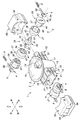
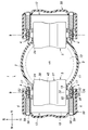
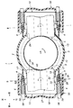
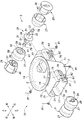
- the perspective view of the container holder which concerns on 1st Embodiment The disassembled perspective view of the container holder which concerns on 1st Embodiment III-III sectional view of Fig. 1 3 is an enlarged view of the main part (engagement structure between the slider and the guide hole).
- Sectional drawing which shows the initial state of the container holder which concerns on 1st Embodiment
- the perspective view of the state which made the container holder which concerns on 1st Embodiment support the container Sectional drawing of the state which made the container holder which concerns on 1st Embodiment support the container Sectional drawing of the state which applied the rotational force to the container in the container holder which concerns on 1st Embodiment
- each direction of the container holder is determined as shown in FIG.
- the container holder 1 includes a base body 3 in which a housing hole 2 is formed, a slider 4 supported by the base body 3, and a roller 5 supported by the base body 3 via the slider 4. , And a spring 6 that urges the roller 5 through the slider 4.
- the base body 3 has a main body portion 11 formed in a bottomed cylindrical shape with one end closed, and a pair of roller support portions 12 protruding outward from the outer surface of the main body portion 11.
- a housing hole 2 that is a bottomed hole is formed inside the main body 11.
- the housing hole 2 extends along the central axis A, has a bottom surface 13 orthogonal to the central axis A at one end (see FIG. 5), and the other end is open.
- the accommodation hole 2 is formed in a circular shape with a cross section centered on the central axis A, and the hole wall is formed on the circumferential surface.
- the container holder 1 is disposed such that the central axis A of the accommodation hole 2 extends vertically and the bottom surface 13 is disposed on the lower side.
- An annular flange portion 14 projecting outward is formed at the upper end of the main body 11, that is, in the vicinity of the opening end of the accommodation hole 2.
- the pair of roller support portions 12 are provided at the front side portion or the rear side portion of the main body portion 11 and are provided at positions that are symmetrical with each other about the central axis A.
- the pair of roller support portions 12 are formed symmetrically with each other.
- the roller support portion 12 on the rear side will be described.
- the roller support portion 12 has an upper wall 16, left and right side walls 17, and a lower wall 18 and has a rectangular tube shape extending in the front-rear direction.
- the roller support portion 12 is joined to the outer surface of the main body portion 11 at the front ends of the upper wall 16, the left and right side walls 17, and the lower wall 18.
- the rear end of the roller support portion 12 is opened rearward.
- the upper wall 16, the left and right side walls 17, and the lower wall 18 constituting the roller support portion 12 protrude rearward from the outer surface of the main body portion 11.
- the left and right side walls 17 generally extend vertically.
- ribs extending in the front-rear direction are protruded for the purpose of reinforcement.
- a pair of auxiliary walls 19 extending from the upper wall 16 to the lower wall 18 are provided inside the left and right side walls 17.
- the front ends of the pair of auxiliary walls 19 are joined to the outer surface of the main body 11.
- the auxiliary wall 19 is formed shorter than the side wall 17 in the front-rear direction, and the rear edge thereof is disposed in front of the rear edge of the side wall 17.
- a guide hole 21 extending in the front-rear direction is formed in each of the left and right side walls 17.
- the guide hole 21 penetrates each side wall 17 from side to side, and the rear end reaches the rear edge of each side wall 17 and opens rearward.
- the front end of the guide hole 21 is a closed end within each side wall 17.
- auxiliary guide holes 22 extending in the front-rear direction are formed in each of the pair of auxiliary walls 19.
- the auxiliary guide hole 22 penetrates each auxiliary wall 19 left and right, and the rear end reaches the rear edge of each auxiliary wall 19 and opens rearward.
- the auxiliary guide hole 22 is provided at a position that coincides with the guide hole 21 in the vertical direction.
- the front end edge of the auxiliary guide hole 22 is a closed end within each side wall 17 and is disposed at substantially the same position as the front end edge of the guide hole 21 in the front-rear direction.
- the front roller support 12 is symmetrical with the rear roller support 12 and will not be described.
- An insertion hole 24 penetrating the side portion of the main body portion 11 in the thickness direction is formed in each of the portions corresponding to the roller support portions 12 on the side portion of the main body portion 11.
- the insertion hole 24 is formed in a portion surrounded by the upper wall 16, the lower wall 18, and the left and right auxiliary walls 19.
- the insertion hole 24 is formed in a substantially rectangular shape whose left and right are long with respect to the top and bottom.
- Each roller support portion 12 supports a roller 5.
- the pair of rollers 5 has the same configuration.
- the roller 5 includes a shaft member 26 and a cylindrical surface layer member 27 attached so as to wrap the shaft member 26.
- the shaft member 26 has a shaft shape, and includes a first shaft member 28 that serves as the rotation axis B of the roller 5, and a pair of second shaft members 29 that are assembled to the outer peripheral portion of the first shaft member 28.
- the first shaft member 28 is disposed at the central portion in the longitudinal direction, and has a rectangular shaft portion 31 having a square cross section and a pair of large-diameter shafts projecting from both end surfaces of the rectangular shaft portion 31 in the longitudinal direction. Part 32 and a pair of small-diameter shaft parts 33 projecting from the projecting end face of each large-diameter shaft part 32.
- the large-diameter shaft portion 32 and the small-diameter shaft portion 33 are circular in cross section.
- the axes of the rectangular shaft portion 31, the pair of large diameter shaft portions 32, and the pair of small diameter shaft portions 33 are arranged coaxially with each other and become the rotation axis B of the roller 5.
- the outer diameter of the large-diameter shaft portion 32 is set to be smaller than any length of each side of the rectangular shaft portion 31, and is set to be larger than the outer diameter of the small-diameter shaft portion 33.
- a disc-shaped flange portion 34 projecting in a direction orthogonal to the rotation axis B is provided at a central portion in the longitudinal direction of the rectangular shaft portion 31, that is, a central portion in the longitudinal direction of the shaft member 26.
- the pair of second shaft members 29 are each formed in a columnar shape, and have a first through hole 36 through which the square shaft portion 31 can pass in the center.
- the first through hole 36 has a cross section complementary to the cross section of the rectangular shaft portion 31.
- the second shaft member 29 has a shaft-side taper portion 37 whose outer diameter decreases toward the end portion on one side in the axial direction of the outer peripheral portion thereof. The outer diameter of the portion on the other side in the axial direction of the outer peripheral portion of the second shaft member 29 is constant.
- the surface layer member 27 includes a cylindrical portion 38 and a bottom plate portion 39 provided at one end of the cylindrical portion 38.
- the bottom plate portion 39 has a second through hole 41 through which the rectangular shaft portion 31 can pass.
- the bottom plate portion 39 has an annular convex portion 42 that protrudes in the axial direction at the peripheral edge portion thereof and extends annularly along the edge portion.
- the cylinder part 38 has a surface layer side taper part 43 whose outer diameter and inner diameter become smaller toward the bottom plate side in the part on the bottom plate side in the longitudinal direction.
- a portion on the side opposite to the bottom plate portion 39 side in the longitudinal direction of the cylindrical portion 38 is formed with a constant outer diameter and inner diameter.
- the second shaft member 29 is inserted into the surface layer member 27 so that the surface layer side taper portion 43 and the shaft side taper portion 37 face each other, and the surface layer member 27 is attached to the second shaft member. Since the inner diameter of the surface layer member 27 is formed larger than the outer diameter of the second shaft member 29, the inner surface of the surface layer member 27 and the second shaft member are mounted in a state where the surface layer member 27 is attached to the second shaft member 29. An air gap is formed between the outer surface of 29. A locking rib 45 protruding radially inward is provided on the inner surface of the surface layer member 27, and a protruding end of the locking rib 45 is locked in a locking groove 46 formed in the second shaft member 29. Thus, the relative rotation between the surface layer member 27 and the second shaft member 29 is restricted. Further, the gap between the surface layer member 27 and the second shaft member 29 is maintained in a predetermined shape by the locking rib 45.
- each end portion of the first shaft member 28 is provided with the second through hole 41 of the surface layer member 27 and the first through hole 36 of the second shaft member 29. Inserted to pass.
- the large diameter shaft portion 32 and the small diameter shaft portion 33 pass through the first through hole 36 and protrude outward from the second shaft member 29.
- the rectangular shaft portion 31 engages with the first through hole 36, and the second shaft member 29 and the first shaft member 28 rotate integrally around the rotation axis B.
- a locking claw (not shown) is formed in the first through hole 36 of the second shaft member 29, and the locking claw is locked in a locking hole 51 formed in the rectangular shaft portion 31.
- the second shaft member 29 is prevented from coming off from the first shaft member 28.
- each tapered portion is disposed at the center in the longitudinal direction. Further, in a state where each second shaft member 29 is assembled to the first shaft member 28, the bottom plate portion 39 of the surface layer member 27 is sandwiched between the flange portion 34 and the second shaft member 29. At this time, the annular projecting portion 42 of each surface layer member 27 is positioned outward in the radial direction from the flange portion 34, and the projecting ends abut against each other. As a result, the flange portion 34 is enclosed by the bottom plate portion 39 and the annular convex portion 42 of the surface layer member 27.
- the surface layer member 27 is formed of a material having higher flexibility and a higher friction coefficient than the shaft member 26 including the first shaft member 28 and the second shaft member 29.
- the surface layer member 27 is preferably formed of a thermoplastic elastomer such as an olefin elastomer or a styrene elastomer.
- the shaft member 26 may be formed of, for example, polycarbonate, ABS, polyacetal, or the like. Further, the surface layer member 27 may be formed with irregularities on the outer peripheral portion or may be subjected to a roughening treatment in order to increase the frictional resistance.
- the outer diameter of the roller 5 configured as described above is set to be smaller in the central portion than in the both ends in the direction of the rotation axis B.
- the roller 5 is more flexible than the shaft member 26 and has an outer peripheral portion formed by the surface layer member 27 having a higher coefficient of friction, so that a large frictional force is easily generated between the roller 5 and the container 60. Yes.
- the surface layer member 27 is easily brought into close contact with the container 60 by being deformed to the gap side.
- the roller 5 is supported by the roller support portion 12 via the pair of left and right sliders 4 at each small-diameter shaft portion 33 disposed at both ends in the rotation axis B direction.
- Each slider 4 has an engaging groove 52 extending in the front-rear direction at the upper part and the lower part.
- the upper edge of the guide hole 21 engages with the upper engagement groove 52, and the lower edge of the guide hole 21 engages with the lower engagement groove 52.
- the slider 4 is supported by the side wall 17 so as to be slidable back and forth within the guide hole 21 extending in the front and rear direction.
- the upper edge portion and the lower edge portion of the guide hole 21 function as guide rails that guide the slider 4.
- the width in the left-right direction of the upper and lower engagement grooves 52 is set to be greater than the thickness of the side wall 17 portion (thickness in the left-right direction).
- the upper edge portion and the lower edge portion of the guide hole 21 can be tilted in the guide groove, and the slider 4 has a predetermined range in the left-right direction around an axis line (vertical axis) parallel to the central axis A. It can be tilted.
- the slider 4 is formed with a bearing hole 54 penetrating in the left-right direction.
- the small diameter shaft portion 33 of the roller 5 is rotatably inserted into the bearing hole 54.
- the inner diameter of the bearing hole 54 is smaller than the outer diameter of the large-diameter shaft portion 32, and the large-diameter shaft portion 32 cannot enter the bearing hole 54.
- the pair of left and right sliders 4 are inserted into the guide holes 21 and supported by the roller support portions 12 after the left and right small-diameter shaft portions 33 of the rollers 5 are inserted into the respective bearing holes 54.
- a cover 55 is coupled to the roller support portion 12 in a state where the roller 5 is supported by the roller support portion 12 via the pair of left and right sliders 4.
- the cover 55 has a box shape and has an inner chamber that receives the upper wall 16, the left and right side walls 17, and the lower wall 18, and closes the open end of the roller support portion 12.
- the cover 55 is coupled to the roller support portion 12 by locking the locking holes 56 formed in the cover 55 to the elastic claws 57 provided on the side wall 17.
- the cover 55 is coupled to the roller support portion 12, the rear end opening of the guide hole 21 is closed by the cover 55, and the slider 4 cannot be detached from the guide hole 21.
- Each slider 4 is provided with a cylindrical spring support shaft 58 projecting from the side opposite to the accommodation hole 2 side (in the case of the slider 4 supported by the rear roller support portion 12).
- a through hole 59 through which the spring support shaft 58 can pass is formed in the cover 55 member.
- the inner diameter of the through hole 59 is larger than the outer shape of the spring support shaft 58, and is formed in a size that does not contact the spring support shaft 58 even when the slider 4 tilts in the left-right direction about the vertical axis.
- the spring support shaft 58 supports a spring 6 that is a compression coil spring.
- a spring support shaft 58 is inserted through the center of the spring 6, and one end abuts against the slider 4 while the other end abuts against the cover 55.
- the slider 4 is urged by the spring 6 in the guide hole 21 toward the accommodation hole 2.
- the pair of left and right sliders 4 urged by the spring 6 abuts against the end of the guide hole 21 on the accommodation hole 2 side, and the roller 5 is partially inserted. It passes through the hole 24 and protrudes into the accommodation hole 2. This state is the initial position.
- the rotation axis B of the roller 5 extends in the tangential direction of the circle with the center axis A as the center.
- the rotation axis B extends in the left-right direction with respect to the central axis A extending in the up-down direction.
- the container holder 1 is attached to a center console (not shown) of an instrument panel (not shown) of an automobile.
- the container holder 1 may be disposed so that an opening is formed in the center console and the base flange portion 34 is engaged with the surface side of the peripheral edge of the opening.
- the roller support part 12 and the cover 55 are arrange
- the container 60 held by the container holder 1 may be, for example, a well-known plastic bottle having a screw cap on the top, a metal can, a paper cup, or the like.
- each roller 5 When inserting the container 60 into the accommodation hole 2, the bottom and sides of the container 60 come into contact with the outer peripheral surface of each roller 5 protruding into the accommodation hole 2.
- each roller 5 receives frictional force from the container 60 and rotates about the rotation axis B, and resists the biasing force of the spring 6 as shown in FIG. However, it moves outward in the radial direction of the accommodation hole 2. That is, the pair of front and rear rollers 5 move in a direction away from each other, and a space in which the container 60 can be inserted is formed between the rollers 5.
- the amount of movement of the receiving hole 2 of each roller 5 outward in the radial direction is determined by the size of the container 60.
- the pair of rollers 5 can appropriately hold the containers 60. Accordingly, the container 60 is stably held between the pair of rollers 5 regardless of the size, and is stably supported in the accommodation hole 2.
- the container 60 When removing the container 60 from the accommodation hole 2, the container 60 may be extracted from between the pair of rollers 5 biased by the spring 6.
- the roller 5 When the container 60 is extracted in the direction along the central axis A, the roller 5 is rotated by the frictional force generated between the container 60 and the roller 5 and is urged by the spring 6 as the container 60 is detached. The roller 5 protrudes into the accommodation hole 2 and returns to the initial state (see FIG. 5).
- the roller 5 Since the roller 5 is formed so that the outer diameter at the intermediate portion in the rotation axis direction is smaller than the outer diameter at both ends, the contact area with the outer peripheral surface of the cylindrical container 60 can be increased. Further, the roller 5 has a surface layer member 27 that is easier to deform than the shaft member 26 (high flexibility) and has a high friction coefficient on the outer peripheral portion, and contacts the container 60 in the surface layer member 27. The contact area with the container 60 can be increased, and the frictional force acting between the roller 5 and the container 60 can be increased. In particular, since a gap is formed between the surface layer member 27 and the second shaft member 29 and the surface layer member 27 is easily deformed to the gap side, the surface layer member 27 is deformed according to the shape of the container 60. Then, the contact area can be increased due to close contact. As described above, since the roller 5 can apply a relatively high frictional force to the container 60, the holding stability of the container 60 is improved.
- a play is set between the engaging groove 52 of the slider 4 and the upper and lower edges of the guide hole 21 in the side wall 17, and the slider 4 is parallel to the central axis A with respect to the side wall 17. Therefore, the rotation axis B of the roller 5 can be tilted about an axis parallel to the center axis A. Therefore, when a rotational force about the central axis A is applied to the container 60 accommodated in the accommodation hole 2, the roller 5 is parallel to the central axis A by the frictional force acting between the outer peripheral surface of the container 60 and the roller 5. A moment about a simple axis is generated. The roller 5 is tilted by this moment and the biasing force of the pair of springs 6 independently applied to both ends of the shaft member 26 of the roller 5. When the roller 5 tilts in the same direction as the rotation direction of the container 60, the contact pressure between the roller 5 and the container 60 increases, and the frictional force acting between the container 60 and the roller 5 increases. Thereby, rotation of the container 60 is suppressed.
- roller 5 is disposed at a diagonal position with the center axis A as a center so that the container 60 can be sandwiched, when the rotational force is applied to the container 60, both the rollers 5 tilt, A frictional force can be generated such that both rollers 5 sandwich the container 60.
- the container holder 1 can prevent the rotation of the container 60 by causing the roller 5 to generate a frictional force even when a rotational force about the central axis A is applied to the accommodated container 60. . Therefore, the user of the container holder 1 rotates only the screw cap without holding the main body side of the container 60 while holding the container 60 having the screw cap at the upper end in the accommodation hole 2. The screw cap can be removed. That is, the user can open the container 60 supported by the container holder 1 with one hand.
- the container holder 70 according to the second embodiment has the slider 4 omitted, and the shaft member 26 of the roller 5 is directly supported by the guide hole 21.
- the same configurations as those of the container holder 1 according to the first embodiment are denoted by the same reference numerals and description thereof is omitted.
- the roller support portion 72 provided on the base 3 has a rectangular tube shape that has both upper walls 16, a pair of side walls 17, and a lower wall 18 and extends in the front-rear direction.
- No auxiliary wall 19 is provided between the side walls 17.
- Each side wall 17 is provided with a guide hole 21.
- Outside auxiliary walls 75 are provided on the left and right outer sides of the respective side walls 17 so as to straddle the guide holes 21 vertically.
- the outer auxiliary wall 75 has an upper wall, a side wall, and a lower wall, has a transverse cross section formed in a groove shape (U shape), and defines a space with the outer surface of the side wall 17.
- a locking hole 76 extending in the front-rear direction is formed in the side wall of the outer auxiliary wall 75.
- An elastic claw 77 is provided at the end of the locking hole 76 on the side opposite to the accommodation hole 2 side.
- the roller 5 has a disk-shaped locking portion 78 projecting radially outward from the small-diameter shaft portion 33.
- the outer diameter of the locking portion 78 is set to be equal to or smaller than the outer diameter of the large-diameter shaft portion 32.
- the locking portion 78 is provided at a position away from the end of the small diameter shaft portion 33 by a predetermined distance.
- the large-diameter shaft portions 32 disposed at both ends of the shaft member 26 are supported by the guide holes 21, so that the roller 5 can slide in the front-rear direction and tilt about an axis parallel to the central axis A. Supported as possible.
- the roller 5 is attached to the roller support portion 72 of the base 3, that is, when both the large-diameter shaft portions 32 are inserted into the guide holes 21, the end portions of the both small-diameter shaft portions 33 abut against the elastic claws 77. Deform.
- the end portion of the small diameter shaft portion 33 passes through the elastic claw 77, and the elastic claw 77 returns to the initial shape.
- the roller 5 Since the elastic claw 77 that has returned to the initial shape prohibits the passage of the small-diameter shaft portion 33, the roller 5 is kept attached to the roller support portion 72. In other words, when the small-diameter shaft portion 33 abuts against the elastic claw 77, the position that is most distant from the accommodation hole 2 of the roller 5 is determined.
- a spring support shaft 82 projects from the outer surface of each side wall 17, and the spring support shaft 82 supports a coil portion of a spring 81 that is a torsion coil spring.
- One end of the spring 81 passes through a hole formed in the lower wall of the outer auxiliary wall 75 and is locked to a portion positioned between the large diameter shaft portion 32 and the locking portion 78 of the small diameter shaft portion 33. .
- the other end of the spring 81 is locked to a spring locking portion 83 protruding from the outer surface of the side wall 17.
- the shaft member 26 of the roller 5 is urged toward the accommodation hole 2 by the independent springs 81 at both ends.
- each large-diameter shaft portion 32 hits the end portion of the guide hole 21, and the roller 5 is positioned closest to the accommodation hole 2.
- the rotation axis B of the roller 5 extends in the tangential direction of the circle with the center axis A as the center.
- the container holder 70 according to the second embodiment has the same effects as the container holder 1 according to the first embodiment. Further, since the container holder 70 does not have the slider 4 and the spring support shaft 58, the spring support shaft 58 does not protrude to the outside even when the roller 5 moves in a direction away from the accommodation hole 2. Therefore, the container holder 70 can be attached in a smaller space than the container holder 1.
- the pair of rollers 5 is arranged at an interval of 180 ° with the central axis A as the center.
- the three rollers 5 may be arranged at an interval of 120 ° with the central axis A as the center.
- Four rollers 5 may be arranged at 90 ° intervals as the center.
- only one roller 5 may be disposed, and the container 60 may be sandwiched between the roller 5 and the side wall of the accommodation hole 2.
Landscapes
- Engineering & Computer Science (AREA)
- Physics & Mathematics (AREA)
- Thermal Sciences (AREA)
- Transportation (AREA)
- Mechanical Engineering (AREA)
- Passenger Equipment (AREA)
- Closures For Containers (AREA)
Abstract
Description
図1及び図2に示すように、容器ホルダ1は、収容孔2が形成された基体3と、基体3に支持されたスライダ4と、スライダ4を介して基体3に支持されたローラ5と、スライダ4を介してローラ5を付勢するばね6とを有している。基体3は、一端が閉塞された有底の筒形に形成された本体部11と、本体部11の外側面から外方に突出する一対のローラ支持部12とを有している。本体部11の内側には有底孔である収容孔2が形成されている。収容孔2は、中心軸線Aに沿って延び、一端に中心軸線Aに直交する底面13を有し(図5参照)、他端が開口している。収容孔2は、本実施形態では横断面が中心軸線Aを中心とした円形に形成されており、孔壁が円周面に形成されている。本実施形態では、収容孔2の中心軸線Aが上下に延び、底面13が下側に配置されるように、容器ホルダ1が配置されているものとする。本体部11の上端、すなわち収容孔2の開口端近傍には、外方に張り出した環状のフランジ部14が形成されている。
第2実施形態に係る容器ホルダ70は、第1実施形態に係る容器ホルダ1と比較して、スライダ4が省略され、ローラ5の軸部材26がガイド孔21に直接に支持されている点が異なる。第2実施形態に係る容器ホルダ70の構成のうち、第1実施形態に係る容器ホルダ1と同様の構成は同一の符号を付して説明を省略する。
Claims (7)
- 有底の収容孔が形成された基体と、
前記基体に支持され、少なくとも一部が前記収容孔内に突出して前記収容孔に収容される容器に当接するローラと、
前記ローラを前記収容孔の内方に付勢する付勢部材とを有し、
前記ローラの回転軸線が、前記収容孔の中心軸線を中心とした円の略接線方向に延び、前記収容孔の径方向にスライド移動可能、かつ前記中心軸線と平行な軸線を中心として所定の範囲で傾動可能となるように、前記ローラは前記基体に支持されていることを特徴とする容器ホルダ。 - 前記ローラは、軸部材と、軸部材の外周面に設けられた表層部材とを有し、
前記表層部材は、前記軸部材よりも可撓性が高く、かつ摩擦係数が高いことを特徴とする請求項1に記載の容器ホルダ。 - 前記軸部材の両端部のそれぞれは、前記基体に延設されたガイド孔に支持され、
前記付勢部材は一対設けられ、前記付勢部材の一方は前記軸部材の一端部を付勢し、前記付勢部材の他方は前記軸部材の他方を付勢することを特徴とする請求項2に記載の容器ホルダ。 - 前記ガイド孔には、前記ガイド孔の延在方向にスライド移動可能かつ前記中心軸線と平行な軸線を中心として所定の範囲で傾動可能にスライダが支持され、
前記軸部材の両端部のそれぞれは、前記スライダに回動可能に支持され、
前記付勢部材のそれぞれは、前記スライダを介して前記軸部材の両端部のそれぞれを付勢することを特徴とする請求項3に記載の容器ホルダ。 - 前記表層部材は、前記軸部材との間に空隙を形成するように前記軸部材に取り付けられ、前記ローラが前記容器に当接する際に、前記表層部材が前記軸部材側に変形可能になっていることを特徴とする請求項2~請求項4のいずれか1つの項に記載の容器ホルダ。
- 前記ローラは、前記回転軸線の方向において中間部が両端部よりも外径が小さく形成されていることを特徴とする請求項2~請求項5のいずれか1つの項に記載の容器ホルダ。
- 前記表層部材は、筒状に形成され、
前記軸部材は、複数の部材を組み合わせて形成されることを特徴とする請求項6に記載の容器ホルダ。
Priority Applications (3)
| Application Number | Priority Date | Filing Date | Title |
|---|---|---|---|
| JP2015544781A JP6445452B2 (ja) | 2013-10-28 | 2014-10-16 | 容器ホルダ |
| CN201480059095.2A CN105682989B (zh) | 2013-10-28 | 2014-10-16 | 容器保持架 |
| US15/032,134 US9718389B2 (en) | 2013-10-28 | 2014-10-16 | Container holder |
Applications Claiming Priority (2)
| Application Number | Priority Date | Filing Date | Title |
|---|---|---|---|
| JP2013-223120 | 2013-10-28 | ||
| JP2013223120 | 2013-10-28 |
Publications (1)
| Publication Number | Publication Date |
|---|---|
| WO2015064039A1 true WO2015064039A1 (ja) | 2015-05-07 |
Family
ID=53003673
Family Applications (1)
| Application Number | Title | Priority Date | Filing Date |
|---|---|---|---|
| PCT/JP2014/005253 Ceased WO2015064039A1 (ja) | 2013-10-28 | 2014-10-16 | 容器ホルダ |
Country Status (4)
| Country | Link |
|---|---|
| US (1) | US9718389B2 (ja) |
| JP (1) | JP6445452B2 (ja) |
| CN (1) | CN105682989B (ja) |
| WO (1) | WO2015064039A1 (ja) |
Cited By (3)
| Publication number | Priority date | Publication date | Assignee | Title |
|---|---|---|---|---|
| JP2017001469A (ja) * | 2015-06-08 | 2017-01-05 | 槌屋ヤック株式会社 | ドリンクホルダー |
| WO2017198832A1 (de) * | 2016-05-20 | 2017-11-23 | Brose Fahrzeugteile Gmbh & Co. Kg, Coburg | Verschlussöffner für ein fahrzeug |
| CN107720659A (zh) * | 2016-08-10 | 2018-02-23 | 奥迪股份公司 | 用于机动车内的瓶启闭装置 |
Families Citing this family (3)
| Publication number | Priority date | Publication date | Assignee | Title |
|---|---|---|---|---|
| JP7842653B2 (ja) | 2022-07-15 | 2026-04-08 | 株式会社Subaru | 容器ホルダ |
| US11820271B1 (en) * | 2023-02-01 | 2023-11-21 | Subaru Corporation | Cup holder |
| DE102023001825A1 (de) | 2023-05-08 | 2024-11-14 | Mercedes-Benz Group AG | Becherhalter für einen Kraftwagen sowie Verfahren |
Citations (5)
| Publication number | Priority date | Publication date | Assignee | Title |
|---|---|---|---|---|
| JPH0920166A (ja) * | 1995-07-04 | 1997-01-21 | Nifco Inc | 車両用カップホルダ |
| JP2008143294A (ja) * | 2006-12-08 | 2008-06-26 | Calsonic Kansei Corp | 車両用カップホルダ装置 |
| JP2008195159A (ja) * | 2007-02-09 | 2008-08-28 | Toyoda Gosei Co Ltd | 容器保持構造 |
| JP2008230570A (ja) * | 2007-03-23 | 2008-10-02 | Kojima Press Co Ltd | 車両用物品保持装置 |
| JP5121436B2 (ja) * | 2007-12-20 | 2013-01-16 | 小島プレス工業株式会社 | 車両用物品保持装置 |
Family Cites Families (4)
| Publication number | Priority date | Publication date | Assignee | Title |
|---|---|---|---|---|
| US4712823A (en) * | 1986-05-05 | 1987-12-15 | Chrysler Motors Corporation | Cup holder apparatus |
| US5706686A (en) * | 1994-01-31 | 1998-01-13 | Delaware Capital Formation, Inc. | Method and apparatus for inside can base reforming |
| JP4296054B2 (ja) | 2003-07-30 | 2009-07-15 | 株式会社イノアックコーポレーション | カップホルダ |
| JP2011185301A (ja) * | 2010-03-04 | 2011-09-22 | Nifco Inc | 軸支持構造 |
-
2014
- 2014-10-16 WO PCT/JP2014/005253 patent/WO2015064039A1/ja not_active Ceased
- 2014-10-16 CN CN201480059095.2A patent/CN105682989B/zh active Active
- 2014-10-16 US US15/032,134 patent/US9718389B2/en active Active
- 2014-10-16 JP JP2015544781A patent/JP6445452B2/ja active Active
Patent Citations (5)
| Publication number | Priority date | Publication date | Assignee | Title |
|---|---|---|---|---|
| JPH0920166A (ja) * | 1995-07-04 | 1997-01-21 | Nifco Inc | 車両用カップホルダ |
| JP2008143294A (ja) * | 2006-12-08 | 2008-06-26 | Calsonic Kansei Corp | 車両用カップホルダ装置 |
| JP2008195159A (ja) * | 2007-02-09 | 2008-08-28 | Toyoda Gosei Co Ltd | 容器保持構造 |
| JP2008230570A (ja) * | 2007-03-23 | 2008-10-02 | Kojima Press Co Ltd | 車両用物品保持装置 |
| JP5121436B2 (ja) * | 2007-12-20 | 2013-01-16 | 小島プレス工業株式会社 | 車両用物品保持装置 |
Cited By (3)
| Publication number | Priority date | Publication date | Assignee | Title |
|---|---|---|---|---|
| JP2017001469A (ja) * | 2015-06-08 | 2017-01-05 | 槌屋ヤック株式会社 | ドリンクホルダー |
| WO2017198832A1 (de) * | 2016-05-20 | 2017-11-23 | Brose Fahrzeugteile Gmbh & Co. Kg, Coburg | Verschlussöffner für ein fahrzeug |
| CN107720659A (zh) * | 2016-08-10 | 2018-02-23 | 奥迪股份公司 | 用于机动车内的瓶启闭装置 |
Also Published As
| Publication number | Publication date |
|---|---|
| JP6445452B2 (ja) | 2018-12-26 |
| US9718389B2 (en) | 2017-08-01 |
| JPWO2015064039A1 (ja) | 2017-03-09 |
| CN105682989B (zh) | 2017-12-12 |
| US20160304020A1 (en) | 2016-10-20 |
| CN105682989A (zh) | 2016-06-15 |
Similar Documents
| Publication | Publication Date | Title |
|---|---|---|
| JP6445452B2 (ja) | 容器ホルダ | |
| JPWO2016178325A1 (ja) | 容器保持具 | |
| JP6146344B2 (ja) | カップホルダ | |
| WO2010113980A1 (ja) | カップホルダー用の径許容機構及びこれを用いたカップホルダー | |
| JP5500797B2 (ja) | キー装置 | |
| KR20160135130A (ko) | 힌지 장치 | |
| JP5234337B2 (ja) | カップホルダー | |
| WO2014133282A1 (ko) | 자동차 컵 홀더의 플랩 조립체 | |
| JP6321242B2 (ja) | カップホルダー | |
| JP4296054B2 (ja) | カップホルダ | |
| JP5657310B2 (ja) | 容器保持装置 | |
| JP2012056415A (ja) | カップホルダ | |
| JP5430111B2 (ja) | カップホルダ | |
| JP5535781B2 (ja) | カップホルダ | |
| JP5809821B2 (ja) | 車両用飲料容器ホルダ | |
| JP5359232B2 (ja) | カップホルダー | |
| JP2007161086A (ja) | 車両用カップホルダ | |
| JP6258595B2 (ja) | カップホルダー | |
| JP5737201B2 (ja) | カップホルダ | |
| JP2008195159A (ja) | 容器保持構造 | |
| JP2008195127A (ja) | 車両用収容物保持装置 | |
| JPH0976811A (ja) | カップホルダーユニット | |
| JP6214966B2 (ja) | カップホルダ | |
| JP2008201228A (ja) | 車両用収容物保持装置 | |
| JP2008230570A (ja) | 車両用物品保持装置 |
Legal Events
| Date | Code | Title | Description |
|---|---|---|---|
| 121 | Ep: the epo has been informed by wipo that ep was designated in this application |
Ref document number: 14857615 Country of ref document: EP Kind code of ref document: A1 |
|
| ENP | Entry into the national phase |
Ref document number: 2015544781 Country of ref document: JP Kind code of ref document: A |
|
| WWE | Wipo information: entry into national phase |
Ref document number: 15032134 Country of ref document: US |
|
| NENP | Non-entry into the national phase |
Ref country code: DE |
|
| 122 | Ep: pct application non-entry in european phase |
Ref document number: 14857615 Country of ref document: EP Kind code of ref document: A1 |