WO2015056691A1 - 端子、ワイヤハーネスおよびワイヤハーネス構造体 - Google Patents
端子、ワイヤハーネスおよびワイヤハーネス構造体 Download PDFInfo
- Publication number
- WO2015056691A1 WO2015056691A1 PCT/JP2014/077385 JP2014077385W WO2015056691A1 WO 2015056691 A1 WO2015056691 A1 WO 2015056691A1 JP 2014077385 W JP2014077385 W JP 2014077385W WO 2015056691 A1 WO2015056691 A1 WO 2015056691A1
- Authority
- WO
- WIPO (PCT)
- Prior art keywords
- terminal
- transition
- sealing
- terminal body
- crimping
- Prior art date
Links
Images


Classifications
-
- H—ELECTRICITY
- H01—ELECTRIC ELEMENTS
- H01R—ELECTRICALLY-CONDUCTIVE CONNECTIONS; STRUCTURAL ASSOCIATIONS OF A PLURALITY OF MUTUALLY-INSULATED ELECTRICAL CONNECTING ELEMENTS; COUPLING DEVICES; CURRENT COLLECTORS
- H01R4/00—Electrically-conductive connections between two or more conductive members in direct contact, i.e. touching one another; Means for effecting or maintaining such contact; Electrically-conductive connections having two or more spaced connecting locations for conductors and using contact members penetrating insulation
- H01R4/10—Electrically-conductive connections between two or more conductive members in direct contact, i.e. touching one another; Means for effecting or maintaining such contact; Electrically-conductive connections having two or more spaced connecting locations for conductors and using contact members penetrating insulation effected solely by twisting, wrapping, bending, crimping, or other permanent deformation
- H01R4/18—Electrically-conductive connections between two or more conductive members in direct contact, i.e. touching one another; Means for effecting or maintaining such contact; Electrically-conductive connections having two or more spaced connecting locations for conductors and using contact members penetrating insulation effected solely by twisting, wrapping, bending, crimping, or other permanent deformation by crimping
-
- H—ELECTRICITY
- H01—ELECTRIC ELEMENTS
- H01R—ELECTRICALLY-CONDUCTIVE CONNECTIONS; STRUCTURAL ASSOCIATIONS OF A PLURALITY OF MUTUALLY-INSULATED ELECTRICAL CONNECTING ELEMENTS; COUPLING DEVICES; CURRENT COLLECTORS
- H01R13/00—Details of coupling devices of the kinds covered by groups H01R12/70 or H01R24/00 - H01R33/00
- H01R13/02—Contact members
- H01R13/15—Pins, blades or sockets having separate spring member for producing or increasing contact pressure
- H01R13/187—Pins, blades or sockets having separate spring member for producing or increasing contact pressure with spring member in the socket
-
- H—ELECTRICITY
- H01—ELECTRIC ELEMENTS
- H01R—ELECTRICALLY-CONDUCTIVE CONNECTIONS; STRUCTURAL ASSOCIATIONS OF A PLURALITY OF MUTUALLY-INSULATED ELECTRICAL CONNECTING ELEMENTS; COUPLING DEVICES; CURRENT COLLECTORS
- H01R4/00—Electrically-conductive connections between two or more conductive members in direct contact, i.e. touching one another; Means for effecting or maintaining such contact; Electrically-conductive connections having two or more spaced connecting locations for conductors and using contact members penetrating insulation
- H01R4/10—Electrically-conductive connections between two or more conductive members in direct contact, i.e. touching one another; Means for effecting or maintaining such contact; Electrically-conductive connections having two or more spaced connecting locations for conductors and using contact members penetrating insulation effected solely by twisting, wrapping, bending, crimping, or other permanent deformation
- H01R4/18—Electrically-conductive connections between two or more conductive members in direct contact, i.e. touching one another; Means for effecting or maintaining such contact; Electrically-conductive connections having two or more spaced connecting locations for conductors and using contact members penetrating insulation effected solely by twisting, wrapping, bending, crimping, or other permanent deformation by crimping
- H01R4/183—Electrically-conductive connections between two or more conductive members in direct contact, i.e. touching one another; Means for effecting or maintaining such contact; Electrically-conductive connections having two or more spaced connecting locations for conductors and using contact members penetrating insulation effected solely by twisting, wrapping, bending, crimping, or other permanent deformation by crimping for cylindrical elongated bodies, e.g. cables having circular cross-section
-
- H—ELECTRICITY
- H01—ELECTRIC ELEMENTS
- H01R—ELECTRICALLY-CONDUCTIVE CONNECTIONS; STRUCTURAL ASSOCIATIONS OF A PLURALITY OF MUTUALLY-INSULATED ELECTRICAL CONNECTING ELEMENTS; COUPLING DEVICES; CURRENT COLLECTORS
- H01R4/00—Electrically-conductive connections between two or more conductive members in direct contact, i.e. touching one another; Means for effecting or maintaining such contact; Electrically-conductive connections having two or more spaced connecting locations for conductors and using contact members penetrating insulation
- H01R4/10—Electrically-conductive connections between two or more conductive members in direct contact, i.e. touching one another; Means for effecting or maintaining such contact; Electrically-conductive connections having two or more spaced connecting locations for conductors and using contact members penetrating insulation effected solely by twisting, wrapping, bending, crimping, or other permanent deformation
- H01R4/18—Electrically-conductive connections between two or more conductive members in direct contact, i.e. touching one another; Means for effecting or maintaining such contact; Electrically-conductive connections having two or more spaced connecting locations for conductors and using contact members penetrating insulation effected solely by twisting, wrapping, bending, crimping, or other permanent deformation by crimping
- H01R4/20—Electrically-conductive connections between two or more conductive members in direct contact, i.e. touching one another; Means for effecting or maintaining such contact; Electrically-conductive connections having two or more spaced connecting locations for conductors and using contact members penetrating insulation effected solely by twisting, wrapping, bending, crimping, or other permanent deformation by crimping using a crimping sleeve
-
- H—ELECTRICITY
- H01—ELECTRIC ELEMENTS
- H01R—ELECTRICALLY-CONDUCTIVE CONNECTIONS; STRUCTURAL ASSOCIATIONS OF A PLURALITY OF MUTUALLY-INSULATED ELECTRICAL CONNECTING ELEMENTS; COUPLING DEVICES; CURRENT COLLECTORS
- H01R4/00—Electrically-conductive connections between two or more conductive members in direct contact, i.e. touching one another; Means for effecting or maintaining such contact; Electrically-conductive connections having two or more spaced connecting locations for conductors and using contact members penetrating insulation
- H01R4/70—Insulation of connections
-
- H—ELECTRICITY
- H01—ELECTRIC ELEMENTS
- H01R—ELECTRICALLY-CONDUCTIVE CONNECTIONS; STRUCTURAL ASSOCIATIONS OF A PLURALITY OF MUTUALLY-INSULATED ELECTRICAL CONNECTING ELEMENTS; COUPLING DEVICES; CURRENT COLLECTORS
- H01R43/00—Apparatus or processes specially adapted for manufacturing, assembling, maintaining, or repairing of line connectors or current collectors or for joining electric conductors
- H01R43/005—Apparatus or processes specially adapted for manufacturing, assembling, maintaining, or repairing of line connectors or current collectors or for joining electric conductors for making dustproof, splashproof, drip-proof, waterproof, or flameproof connection, coupling, or casing
-
- H—ELECTRICITY
- H01—ELECTRIC ELEMENTS
- H01R—ELECTRICALLY-CONDUCTIVE CONNECTIONS; STRUCTURAL ASSOCIATIONS OF A PLURALITY OF MUTUALLY-INSULATED ELECTRICAL CONNECTING ELEMENTS; COUPLING DEVICES; CURRENT COLLECTORS
- H01R43/00—Apparatus or processes specially adapted for manufacturing, assembling, maintaining, or repairing of line connectors or current collectors or for joining electric conductors
- H01R43/04—Apparatus or processes specially adapted for manufacturing, assembling, maintaining, or repairing of line connectors or current collectors or for joining electric conductors for forming connections by deformation, e.g. crimping tool
- H01R43/048—Crimping apparatus or processes
-
- H—ELECTRICITY
- H01—ELECTRIC ELEMENTS
- H01R—ELECTRICALLY-CONDUCTIVE CONNECTIONS; STRUCTURAL ASSOCIATIONS OF A PLURALITY OF MUTUALLY-INSULATED ELECTRICAL CONNECTING ELEMENTS; COUPLING DEVICES; CURRENT COLLECTORS
- H01R13/00—Details of coupling devices of the kinds covered by groups H01R12/70 or H01R24/00 - H01R33/00
- H01R13/02—Contact members
- H01R13/10—Sockets for co-operation with pins or blades
- H01R13/11—Resilient sockets
-
- H—ELECTRICITY
- H01—ELECTRIC ELEMENTS
- H01R—ELECTRICALLY-CONDUCTIVE CONNECTIONS; STRUCTURAL ASSOCIATIONS OF A PLURALITY OF MUTUALLY-INSULATED ELECTRICAL CONNECTING ELEMENTS; COUPLING DEVICES; CURRENT COLLECTORS
- H01R4/00—Electrically-conductive connections between two or more conductive members in direct contact, i.e. touching one another; Means for effecting or maintaining such contact; Electrically-conductive connections having two or more spaced connecting locations for conductors and using contact members penetrating insulation
- H01R4/10—Electrically-conductive connections between two or more conductive members in direct contact, i.e. touching one another; Means for effecting or maintaining such contact; Electrically-conductive connections having two or more spaced connecting locations for conductors and using contact members penetrating insulation effected solely by twisting, wrapping, bending, crimping, or other permanent deformation
- H01R4/18—Electrically-conductive connections between two or more conductive members in direct contact, i.e. touching one another; Means for effecting or maintaining such contact; Electrically-conductive connections having two or more spaced connecting locations for conductors and using contact members penetrating insulation effected solely by twisting, wrapping, bending, crimping, or other permanent deformation by crimping
- H01R4/188—Electrically-conductive connections between two or more conductive members in direct contact, i.e. touching one another; Means for effecting or maintaining such contact; Electrically-conductive connections having two or more spaced connecting locations for conductors and using contact members penetrating insulation effected solely by twisting, wrapping, bending, crimping, or other permanent deformation by crimping having an uneven wire-receiving surface to improve the contact
-
- H—ELECTRICITY
- H01—ELECTRIC ELEMENTS
- H01R—ELECTRICALLY-CONDUCTIVE CONNECTIONS; STRUCTURAL ASSOCIATIONS OF A PLURALITY OF MUTUALLY-INSULATED ELECTRICAL CONNECTING ELEMENTS; COUPLING DEVICES; CURRENT COLLECTORS
- H01R4/00—Electrically-conductive connections between two or more conductive members in direct contact, i.e. touching one another; Means for effecting or maintaining such contact; Electrically-conductive connections having two or more spaced connecting locations for conductors and using contact members penetrating insulation
- H01R4/58—Electrically-conductive connections between two or more conductive members in direct contact, i.e. touching one another; Means for effecting or maintaining such contact; Electrically-conductive connections having two or more spaced connecting locations for conductors and using contact members penetrating insulation characterised by the form or material of the contacting members
- H01R4/62—Connections between conductors of different materials; Connections between or with aluminium or steel-core aluminium conductors
Definitions
- the present invention relates to a wire harness used for an automobile or the like.
- connection between an electric wire and a terminal in an automobile wire harness is generally a crimp bonding in which the electric wire is crimped with a terminal called an open barrel type.
- a wire harness when moisture or the like adheres to the connection portion between the electric wire and the terminal, the oxidation of the metal surface used for the electric wire proceeds, and the resistance at the joint increases.
- the metal used for an electric wire and a terminal differs, the corrosion between different metals will advance. The progress of the corrosion of the metal material in the connection portion causes cracks in the connection portion and contact failure, and thus cannot be affected by the product life.
- wire harnesses in which the electric wires are made of an aluminum alloy and the terminals are made of a copper alloy are being put into practical use, and the problem of corrosion at the joints has become prominent.
- Patent Document 2 A method for protecting from adhesion of seawater or the like has been proposed (Patent Document 2).
- This invention is made in view of such a problem, and it aims at providing the terminal which can improve the intensity
- the first invention is a terminal connected to the coated conductor, wherein the terminal main body and the cylindrical crimping part are integrally formed via a transition part, and the crimping part is Other parts are sealed except for the part where the covered conducting wire is inserted, and at least part of the transition part is directed from the sealing part provided on the transition part side toward the side part of the terminal body.
- the terminal is characterized in that a continuous surface is formed, and the bottom portion of the transition portion and the surface are separated from the sealing portion toward the side portion of the terminal body.
- the sealing portion is formed by overlapping a lower plate and an upper plate, and the upper plate constituting the sealing portion is formed integrally and continuously up to a side portion of the terminal body. It is desirable that a surface be formed.
- the surface is preferably a curved surface that curves upward in a cross section.
- the sealing part provided on the transition part side which is an end part of the crimping part, is sealed over the entire width of the crimping part, and in a plan view, the edge part of the sealing part on the transition part side is:
- the center in the width direction of the sealing portion may be formed so as to protrude toward the transition portion side with respect to both sides in the width direction of the sealing portion.
- a notch may be formed in at least a part of a side portion of the terminal body between the connection portion of the terminal body and the transition portion and an upper portion of the terminal body.
- the notch may be continuously formed from a side surface of the terminal body to an upper surface of the terminal body.
- the strength of the transition portion is improved by forming a continuous surface from the sealing portion to the side surface of the terminal body in the transition portion and starting up gradually away from the bottom of the transition portion. can do.
- the above-described rise of the surface can be formed gently.
- the notch is formed in the side surface of the terminal body at the connection portion from the transition section to the terminal body, it is possible to eliminate a sudden rising portion on the side surface of the transition section. For this reason, the distance between the upper edge portion of the terminal body and the sealing portion is increased, and stress concentration can be reduced. In addition, by forming the notch, it is not necessary to increase the length of the transition portion, and it is possible to prevent the length of the entire terminal from increasing.
- Such a notch may be continued to the top of the terminal body.
- a second invention is a wire harness to which a coated conductor and a terminal are connected, wherein the terminal is integrally formed with a terminal main body and a cylindrical crimp part via a transition part, Except for the part where the covered conductor is inserted, other parts are sealed, and the covered conductor is crimped to the crimp part, and at least a part of the transition part is provided on the transition part side.
- a curved surface continuous from the sealing portion toward the side portion of the terminal body is formed, and the bottom portion of the transition portion and the curved surface are separated from the sealing portion toward the side portion of the terminal body. It is a wire harness characterized by going.
- the sealing part provided on the transition part side which is an end part of the crimping part, is sealed over the entire width of the crimping part, and in a plan view, the edge part of the sealing part on the transition part side is:
- the center in the width direction of the sealing portion may be formed so as to protrude toward the transition portion side with respect to both sides in the width direction of the sealing portion.
- a notch may be formed in at least a part of a side portion of the terminal body between the connection portion of the terminal body and the transition portion and an upper portion of the terminal body.
- the conductor of the coated conductor may be made of an aluminum material.
- the strength of the transition portion is improved by forming a continuous surface from the sealing portion to the side surface of the terminal body in the transition portion and starting up gradually away from the bottom of the transition portion.
- damage to the terminals can be suppressed.
- the above-described rise of the surface can be formed gently, and damage to the terminal can be suppressed.
- the notch can prevent stress from concentrating on the rising part from the sealing part to the terminal body without increasing the terminal length.
- a third invention is a wire harness structure in which a plurality of wire harnesses are bundled, wherein the wire harness is connected to a covered conductor and a terminal, and the terminal is connected to a terminal body and a cylindrical crimp.
- the crimping part is sealed except for the part into which the coated conductor is inserted, and the coated conductor is crimped to the crimped part.
- a curved surface that is continuous from a sealing portion provided on the transition portion side toward a side portion of the terminal body is formed on at least a part of the transition portion, and the side portion of the terminal body is formed from the sealing portion.
- the wire harness structure is characterized in that the bottom of the transition portion and the curved surface are separated from each other.
- a plurality of wire harnesses can be bundled and used.
- the present invention it is possible to provide a terminal capable of improving the strength of the transition portion, a wire harness using the terminal, and a wire harness structure.
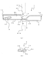
- FIG. (A) is a longitudinal sectional view of the terminal 1, and (b) is a sectional view taken along the line CC of (a).
- (A), (b) is a top view of the transition part 4.
- FIG. It is a figure which shows the crimping
- (A) is a longitudinal sectional view of the terminal 1a
- (b) is a sectional view taken along line AA in (a)
- (c) is a sectional view taken along line BB in (a).
- the longitudinal cross-sectional view which shows the terminal 1e. (A), (b) is a top view of the transition part 4, Comprising: The figure which shows the other form of the sealing part 22.
- FIG. The perspective view which shows the terminal 1f. (A) is a longitudinal sectional view of the terminal 1f, (b) is a sectional view taken along the line DD of (a), and (c) is a sectional view taken along the line EE of (a).
- (A), (b) is a figure which shows the other aspect of the notch 12.
- FIG. 1 is a perspective view of the terminal 1
- FIG. 2A is a longitudinal sectional view of the terminal 1.
- the terminal 1 includes a terminal body 3 and a crimping portion 5.
- a transition portion 4 is formed between the terminal body 3 and the crimping portion 5.
- the transition part 4 is formed so as to continue from the sealing part 22 to at least the bottom and side parts of the terminal body 3.
- Terminal 1 is made of copper.
- the terminal body 3 is formed by forming a plate material having a predetermined shape into a cylindrical body having a rectangular cross section.
- the terminal body 3 has an elastic contact piece 15 formed at the front end portion 17 by folding a plate material into a rectangular cylinder.
- the terminal body 3 is connected by inserting a male terminal or the like from the front end portion 17.
- the crimping part 5 is formed by rounding so that the cross section becomes a circular cylindrical body, butting the side edge parts together and joining and joining them at the joining part 21.
- the side where the edge portions of the crimping part 5 are joined together (the upper side in FIG. 2A) is the upper side of the terminal, and the opposite surface side (the lower side in FIG. 2A) is the terminal.
- a covered conductor 23 to be described later is inserted from the rear end portion 19 of the crimp portion 5 formed in a cylindrical shape.
- a sealing portion 22 is provided at the front end portion (terminal body 3 side) of the crimping portion 5.
- the sealing portion 22 is sealed so that the bottom portion (lower plate) of the terminal body 3 and the plate portion on the upper surface side (upper plate) overlap. That is, the crimping part 5 is sealed except for the rear end part 19 into which the covered conducting wire 23 is inserted.
- the junction part 21 and the sealing part 22 are welded by laser welding etc., for example.
- the transition part 4 has a surface 14 formed upward.
- FIG. 2B is a cross-sectional view taken along the line CC of FIG.
- the surface 14 is a surface (curved surface) formed upward (upward) so as to face the bottom 6a. That is, the transition part 4 has a shape in which the upper edge of the side part 8a is bent inward in the cross section.
- the upper plate of the sealing portion 22 is integrally continuous with the side portion 8 b of the terminal body 3. That is, the surface 14 faces the upper surface at the boundary portion with the sealing portion 22, and the surface 14 faces sideways at the boundary portion with the side portion 8b (the surface (normal line) direction of the surface 14 is It rotates about 90 degrees between the sealing part 22 and the side part 8b).
- the rotation angle in the surface direction of the surface 14 from the boundary portion of the sealing portion 22 changes monotonously according to the distance from the sealing portion 22.
- the surface 14 is formed to be inclined so as to curve upward from the end portion of the sealing portion 22.
- a notch 33 corresponding to the shape of the surface 14 is formed in a part of the molds 31 a and 31 b for crushing the upper plate and the lower plate of the sealing portion 22. What is necessary is just to do (FIG. 2 (a)).
- FIG. 3 is a partial plan view of the transition section 4.
- the surface 14 gradually spreads outward from the end portion of the sealing portion 22 toward the terminal body 3 side (lower side in the figure) while gradually leaving the bottom portion.
- the end portion of the surface 14 may be shifted to the outside from the center of the sealing portion 22, as shown in FIG. ), It can also be at the approximate center of the sealing portion 22.
- the form of the surface 14 is not particularly limited, and the bottom portion 6a and the surface 14 are in contact with each other at the end of the sealing portion 22, and the upper surface and the surface 14 of the bottom portion 6a are moved toward the terminal body 3 side. It is only necessary that the bottom surface of the gradual separation. Further, at the end portion of the sealing portion 22, the surface 14 and the bottom portion 6 a are substantially parallel, and the edge portion of the surface 14 may gradually rise outward and continue to the side portion 8 b as it goes to the terminal body 3 side. .
- FIG. 4 is a diagram illustrating a connection process between the terminal 1 and the covered conductor 23.
- the covered conducting wire 23 is inserted into the tubular crimping part 5.
- the crimping part 5 is rounded into a substantially cylindrical shape, and the edges are joined by the joining part 21.
- a sealing portion 22 is provided at the front end portion (terminal body 3 side) of the crimping portion 5. That is, the crimping part 5 is sealed except for the rear end part 19 into which the covered conducting wire 23 is inserted.
- the conductor 25 is covered with an insulating coating 27.
- the conducting wire 25 is made of, for example, an aluminum-based material.
- a part of the cover 27 at the tip of the covered conductor 23 is peeled off to expose the conductor 25.
- coated part 27 what is normally used in the field
- the crimping part 5 is compressed by a die not shown. Thereby, the crimping
- FIG. 4 (b) the crimping part 5 can be sealed by the close contact between the crimping part 5 and the covering part 27. At this time, other parts than the rear end part 19 of the crimping part 5 are sealed in a watertight manner by the joining part 21 and the sealing part 22, so that the intrusion of moisture into the crimping part 5 can be prevented.
- the wire harness 30 is manufactured.
- the surface 14 is provided between the sealing portion 22 and the terminal body 3, the strength of the transition portion 4 is improved. For this reason, it is possible to prevent the transition portion 4 from being damaged when the terminal 1 is molded or used.
- FIG. 5 is a perspective view showing a terminal 1a according to the second embodiment
- FIG. 6A is a longitudinal sectional view of the terminal 1a.
- components having the same functions as those of the terminal 1 are denoted by the same reference numerals as those in FIG.
- the terminal 1 a has substantially the same configuration as the terminal 1, but differs in that a notch 12 is formed in a part of the side surface of the terminal body 3.
- the transition part 4 is formed so as to be connected to the notch 12 through the surface 14 from the end part (transition part 4 side) of the sealing part 22. That is, the bottom part of the transition part 4 is continuous with the bottom part of the terminal body 3, and at least a part of the side part rising from the sealing part 22 of the transition part 4 and the surface 14 are continuous with the side part 8 b of the terminal body 3.
- FIG. 6 (b) is a cross-sectional view taken along line AA in FIG. 6 (a)
- FIG. 6 (c) is a cross-sectional view taken along line BB in FIG. 6 (a).
- the bottom portion 6a of the transition portion 4 and the bottom portion 6b of the terminal body 3 are continuous.
- the side part 8 a and the surface 14 of the transition part 4 rise gradually from the sealing part 22 side and continue to the notch 12 formed in the side part 8 b of the terminal body 3.
- the distance from the sealing part 22 to the terminal body 3 is increased by gently raising the transition part 4 from the sealing part 22 to the terminal body 3, stress concentration in the transition part 4 can be reduced. it can.
- the required lengths of the terminal body 3 and the crimping portion 5 are defined, and the upper surface of the terminal body 3 needs to have a specified length in consideration of connectivity. That is, only the terminal body 3 cannot be shortened. Therefore, when the transition portion 4 is gently raised, there is a problem that the total length of the terminal becomes long.
- the transition portion 4 can gently rise from the side portion 8a to the side portion 8b. That is, there is no sudden rise from the end portion of the sealing portion 22 toward the upper portion of the terminal body 3 (for example, a substantially vertical rise with respect to the bottom portion 6a). For this reason, the distance between the terminal body 3 and the sealing portion 22 is increased, and the force applied to the terminal body 3 causes the base portion of the transition portion 4 (near the boundary portion with the sealing portion 22) or the upper portion of the terminal body 3 to be close. It is possible to suppress the occurrence of stress concentration.
- the formation of the surface 14 becomes easier by providing the notch 12. Further, the rise of the surface 14 does not become abrupt.
- the shape of the notch 12 is not limited to that shown in FIG. That is, as shown in FIG. 6, the notch 12 is not formed in the side portion 8b from the lower side of the side portion 8b until reaching the upper portion of the terminal body, but another form may be adopted.
- the notch 12 is not formed so as to reach the upper part of the terminal body 3, but a part of the side part 8b is notched and the upper edge of the terminal body 3 (transition) You may form so that it may connect with the upper edge part of the part 4 side.
- the notch 12 may be continuously formed not only on the side portion 8 b but also on the upper portion of the terminal body 3. That is, the notch 12 may be formed continuously from the side surface of the terminal body 3 to the upper surface of the terminal body 3, and a part of the upper portion of the terminal body 3 may be cut away. Thus, even if the notch 12 is formed in the side portion and part of the upper portion while ensuring the length of the terminal body 3, the same effect can be obtained.
- the form of the notch 12 may be any. However, it is desirable that the shape of the notch 12 be formed with a curve that is as gentle as possible.
- the shape of the surface 14 is not limited to that shown in FIG.
- the surface 14 may be formed to be curved downward.
- a sealing mold matched to the curved shape may be used. By setting it as such a curved shape, the intensity
- the shape like the surface 14 may be formed not only on the upper surface of the transition portion 4, but also on the lower surface. That is, you may form so that the bottom part 6a may bulge below as it goes to the terminal main body 3 from the sealing part 22.
- the bottom portion 6a to the bottom portion 6b may not be formed straight, but may be formed so that the surface 14 and the bottom portion 6a spread vertically from the sealing portion 22 as a starting point.
- FIG. 11 is a partial plan view of the transition section 4.
- the sealing shape of the sealing portion 22 is different. That is, in the above-described example, as shown in FIG. 3, the sealing portion 22 is formed over the entire width direction (left-right direction in the drawing) of the terminal 1, and the length of the sealing portion 22 (up-down direction in the drawing). The length is formed in a substantially rectangular shape regardless of the width position.
- the form of the sealing portion 22 changes depending on the width position.
- the vicinity of the substantially central portion in the width direction of the sealing portion 22 protrudes toward the transition portion 4 side with respect to both end portions in the width direction of the sealing portion 22. It becomes a form. That is, the sealing portion 22 has a tapered shape so that the sealing length gradually decreases from the vicinity of the center portion.
- the taper shape may be a straight line or a curved line.
- the surface 14 mentioned above can be formed more easily by shortening the sealing length near the both ends of the width direction of the sealing part 22. Further, in the vicinity of both end portions of the sealing portion 22, the form in which the surface 14 gradually moves away from the bottom portion 6 a toward the terminal body 3 from the sealing portion 22 side can be made gentler.
- the substantially central portion of the sealing portion 22 has a length that can be reliably sealed, the water tightness of the crimping portion 5 can be ensured.
- FIG. 12 is a perspective view of the terminal 1f
- FIG. 13 (a) is a longitudinal sectional view of the terminal 1f.
- the terminal 1f has substantially the same configuration as that of the terminal 1 except that the surface 14 is not formed, and the process for forming the wire harness is also the same.
- a notch 12 is provided in a part of the side surface of the terminal body 3.
- the transition part 4 is formed so as to be connected to the notch 12 from the end part (transition part 4 side) of the sealing part 22. That is, the bottom part of the transition part 4 is continuous with the bottom part of the terminal body 3, and at least a part of the side part rising from the sealing part 22 of the transition part 4 is continuous with the side part of the terminal body 3.
- the sealing part 22 like FIG. 3 or FIG.
- FIG. 13 (b) is a cross-sectional view taken along the line DD of FIG. 13 (a)
- FIG. 13 (c) is a cross-sectional view taken along the line EE of FIG. 13 (a).
- the bottom portion 6a of the transition portion 4 and the bottom portion 6b of the terminal body 3 are continuous.
- the side portion 8 a of the transition portion 4 gradually rises from the sealing portion 22 side and continues to the notch 12 formed in the side portion 8 b of the terminal body 3.
- the notch 12 As described above, by providing the notch 12, it is possible to make the sudden rise of the portion connected to the terminal main body 3 from the end of the sealing portion 22 (end on the transition portion 4 side). For this reason, the stress concentration generated at the boundary between the transition portion 4 and the terminal body 3 can be reduced by the force generated in the terminal body 3 when the terminal 1 is molded or used.
- the shape of the notch 12 is not limited to that shown in FIG. That is, as shown in FIG. 13, the notch 12 is not formed in the side portion 8b from the lower side of the side portion 8b until reaching the upper portion of the terminal body, but another form may be adopted.
- the notch 12 is not formed so as to reach the upper part of the terminal body 3, but a part of the side part 8 b is notched and the edge (transition) of the upper part of the terminal body 3 is formed. You may form so that it may connect with the upper edge part of the part 4 side. Further, as shown in FIG. 14B, even if the notch 12 is formed only in a part of the side portion 8b without connecting to the upper portion of the terminal body 3, the effect can be obtained.
- the notch 12 may be continuously formed not only on the side portion 8 b but also on the upper portion of the terminal body 3. That is, the notch 12 may be formed continuously from the side surface of the terminal body 3 to the upper surface of the terminal body 3, and a part of the upper portion of the terminal body 3 may be cut away. Thus, even if the notch 12 is formed in the side portion and part of the upper portion while ensuring the length of the terminal body 3, the same effect can be obtained.
- the form of the notch 12 may be any. However, it is desirable that the shape of the notch 12 be formed with a curve that is as gentle as possible.
- a plurality of wire harnesses according to the present invention can be bundled and used.
- a structure in which a plurality of wire harnesses are bundled in this way is referred to as a wire harness structure.
Landscapes
- Engineering & Computer Science (AREA)
- Manufacturing & Machinery (AREA)
- Connections Effected By Soldering, Adhesion, Or Permanent Deformation (AREA)
Abstract
Description
以下、図面に基づいて、本発明の第1の実施の形態について詳細に説明する。図1は、端子1の斜視図であり、図2(a)は、端子1の縦断面図である。
次に、第2の実施の形態について説明する。図5は、第2の実施の形態にかかる端子1aを示す斜視図であり、図6(a)は、端子1aの縦断面図である。なお、以下の説明において、端子1と同一の機能を奏する構成については、図1等と同一の符号を付し、重複する説明を省略する。
次に、第3の実施の形態について説明する。図11は、トランジション部4の部分平面図である。第3の実施形態は、封止部22の封止形状が異なる。すなわち、前述した例では、図3に示すように、封止部22は、端子1の幅方向(図中左右方向)の全体にわたって形成され、封止部22の長さ(図中上下方向の長さ)は幅位置によらず略一定に矩形で形成される。
3………端子本体
4………トランジション部
5………圧着部
6a、6b………底部
8a、8b………側部
12………切欠き
14………面
15………弾性接触片
17………前端部
19………後端部
21………接合部
22………封止部
23………被覆導線
25………導線
27………被覆部
30………ワイヤハーネス
31a、31b………金型
33………切欠き
Claims (11)
- 被覆導線と接続される端子であって、
端子本体と筒状の圧着部とがトランジション部を介して一体に形成され、
前記圧着部は、前記被覆導線が挿入される部位を除き、他の部位が封止されており、
前記トランジション部の少なくとも一部には、前記トランジション部側に設けられる封止部から前記端子本体の側部に向かって連続する面が形成され、前記封止部から前記端子本体の側部に向かって、前記トランジション部の底部と、前記面とが離れていくことを特徴とする端子。 - 前記封止部は、下板と上板とが重ね合わさって形成されており、
前記封止部を構成する前記上板が前記端子本体の側部まで連続して一体に形成されたことで前記面が形成されていることを特徴とする請求項1に記載の端子。 - 前記面は、断面において上方に向かって湾曲する湾曲面であることを特徴とする請求項1記載の端子。
- 前記圧着部の端部であって、前記トランジション部側に設けられる前記封止部は、前記圧着部の全幅にわたって封止され、
平面視において、前記封止部の前記トランジション部側の縁部は、前記封止部の幅方向中央が、前記封止部の幅方向の両側に対して、前記トランジション部側に張り出すように形成されることを特徴とする請求項1記載の端子。 - 前記端子本体の側部であって、前記端子本体の前記トランジション部との接続部と、前記端子本体の上部との間の少なくとも一部に、切欠きが形成されることを特徴とする請求項1記載の端子。
- 前記切欠きは、前記端子本体の側面から前記端子本体の上面まで連続して形成されることを特徴とする請求項5記載の端子。
- 被覆導線と端子とが接続されるワイヤハーネスであって、
前記端子は、端子本体と筒状の圧着部とがトランジション部を介して一体に形成され、
前記圧着部は、前記被覆導線が挿入される部位を除き、他の部位が封止され、前記圧着部に、前記被覆導線が圧着されており、
前記トランジション部の少なくとも一部には、前記トランジション部側に設けられる封止部から前記端子本体の側部に向かって連続する湾曲面が形成され、前記封止部から前記端子本体の側部に向かって、前記トランジション部の底部と、前記湾曲面とが離れていくことを特徴とするワイヤハーネス。 - 前記圧着部の端部であって、前記トランジション部側に設けられる前記封止部は、前記圧着部の全幅にわたって封止され、
平面視において、前記封止部の前記トランジション部側の縁部は、前記封止部の幅方向中央が、前記封止部の幅方向の両側に対して、前記トランジション部側に張り出すように形成されることを特徴とする請求項7記載のワイヤハーネス。 - 前記端子本体の側部であって、前記端子本体の前記トランジション部との接続部と、前記端子本体の上部との間の少なくとも一部に、切欠きが形成されることを特徴とする請求項7記載のワイヤハーネス。
- 前記被覆導線の導線がアルミニウム系材料で構成されることを特徴とする請求項7記載のワイヤハーネス。
- 複数本のワイヤハーネスが束ねられたワイヤハーネス構造体であって、
前記ワイヤハーネスは、被覆導線と端子とが接続されており、
前記端子は、端子本体と筒状の圧着部とがトランジション部を介して一体に形成され、
前記圧着部は、前記被覆導線が挿入される部位を除き、他の部位が封止され、前記圧着部に、前記被覆導線が圧着されており、
前記トランジション部の少なくとも一部には、前記トランジション部側に設けられる封止部から前記端子本体の側部に向かって連続する湾曲面が形成され、前記封止部から前記端子本体の側部に向かって、前記トランジション部の底部と、前記湾曲面とが離れていくことを特徴とするワイヤハーネス構造体。
Priority Applications (6)
| Application Number | Priority Date | Filing Date | Title |
|---|---|---|---|
| CN201480054865.4A CN105637707B (zh) | 2013-10-15 | 2014-10-15 | 端子、线束和线束结构体 |
| EP14854866.2A EP3059805B1 (en) | 2013-10-15 | 2014-10-15 | Terminal and wire harness |
| JP2015542626A JP6440626B2 (ja) | 2013-10-15 | 2014-10-15 | 端子、ワイヤハーネスおよびワイヤハーネス構造体 |
| KR1020167008482A KR101869170B1 (ko) | 2013-10-15 | 2014-10-15 | 단자, 와이어하니스 및 와이어하니스 구조체 |
| US15/088,425 US9941601B2 (en) | 2013-10-15 | 2016-04-01 | Terminal, wire harness, and wire-harness structure |
| US15/908,619 US20180191086A1 (en) | 2013-10-15 | 2018-02-28 | Terminal, wire harness, and wire-harness structure |
Applications Claiming Priority (4)
| Application Number | Priority Date | Filing Date | Title |
|---|---|---|---|
| JP2013-214652 | 2013-10-15 | ||
| JP2013214652 | 2013-10-15 | ||
| JP2013-214672 | 2013-10-15 | ||
| JP2013214672 | 2013-10-15 |
Related Child Applications (1)
| Application Number | Title | Priority Date | Filing Date |
|---|---|---|---|
| US15/088,425 Continuation US9941601B2 (en) | 2013-10-15 | 2016-04-01 | Terminal, wire harness, and wire-harness structure |
Publications (1)
| Publication Number | Publication Date |
|---|---|
| WO2015056691A1 true WO2015056691A1 (ja) | 2015-04-23 |
Family
ID=52828134
Family Applications (1)
| Application Number | Title | Priority Date | Filing Date |
|---|---|---|---|
| PCT/JP2014/077385 WO2015056691A1 (ja) | 2013-10-15 | 2014-10-15 | 端子、ワイヤハーネスおよびワイヤハーネス構造体 |
Country Status (6)
| Country | Link |
|---|---|
| US (2) | US9941601B2 (ja) |
| EP (1) | EP3059805B1 (ja) |
| JP (1) | JP6440626B2 (ja) |
| KR (1) | KR101869170B1 (ja) |
| CN (1) | CN105637707B (ja) |
| WO (1) | WO2015056691A1 (ja) |
Cited By (1)
| Publication number | Priority date | Publication date | Assignee | Title |
|---|---|---|---|---|
| JP2017183185A (ja) * | 2016-03-31 | 2017-10-05 | 古河電気工業株式会社 | ジョイント端子、連結電線、電線接続構造体、及び連結電線の製造方法 |
Families Citing this family (4)
| Publication number | Priority date | Publication date | Assignee | Title |
|---|---|---|---|---|
| JP6706549B2 (ja) * | 2016-06-16 | 2020-06-10 | ヒロセ電機株式会社 | 基板との接触に用いる端子、この端子を用いたコネクタ、及び、このコネクタを有するコネクタ装置 |
| EP3471212A1 (en) * | 2017-10-12 | 2019-04-17 | Aptiv Technologies Limited | Electrical connecting cable |
| JP2020017407A (ja) * | 2018-07-25 | 2020-01-30 | 矢崎総業株式会社 | アルミニウム電線圧着端子、圧着装置、および圧着方法 |
| JP7073429B2 (ja) * | 2020-03-18 | 2022-05-23 | 矢崎総業株式会社 | 端子付き電線の製造方法、及び、端子付き電線 |
Citations (7)
| Publication number | Priority date | Publication date | Assignee | Title |
|---|---|---|---|---|
| JP2002184479A (ja) * | 2000-12-18 | 2002-06-28 | Jst Mfg Co Ltd | 雌圧着端子 |
| JP2004071437A (ja) * | 2002-08-08 | 2004-03-04 | Sumitomo Wiring Syst Ltd | 自動車用アース端子と電線の防水接続構造 |
| JP2004111058A (ja) | 2002-09-13 | 2004-04-08 | Furukawa Electric Co Ltd:The | アルミ電線用端子及びコネクタ |
| JP2006331931A (ja) | 2005-05-27 | 2006-12-07 | Mitsubishi Cable Ind Ltd | 電線の接続構造及びその接続方法 |
| JP2010186692A (ja) * | 2009-02-13 | 2010-08-26 | Yazaki Corp | 接続端子 |
| WO2011122622A1 (ja) * | 2010-03-30 | 2011-10-06 | 古河電気工業株式会社 | 圧着端子、接続構造体及びコネクタ |
| JP2013062206A (ja) * | 2011-09-15 | 2013-04-04 | Furukawa Electric Co Ltd:The | 圧着端子、接続構造体及びコネクタ |
Family Cites Families (3)
| Publication number | Priority date | Publication date | Assignee | Title |
|---|---|---|---|---|
| JP5557378B2 (ja) * | 2010-03-23 | 2014-07-23 | 矢崎総業株式会社 | 圧着端子および圧着端子の電線に対する圧着構造 |
| JP5741502B2 (ja) * | 2011-07-26 | 2015-07-01 | 株式会社オートネットワーク技術研究所 | 端子付き電線およびその製造方法 |
| CN108258442B (zh) * | 2013-02-23 | 2020-09-18 | 古河电气工业株式会社 | 筒状体和压接端子的制造方法、以及压接端子的制造装置 |
-
2014
- 2014-10-15 WO PCT/JP2014/077385 patent/WO2015056691A1/ja active Application Filing
- 2014-10-15 JP JP2015542626A patent/JP6440626B2/ja active Active
- 2014-10-15 KR KR1020167008482A patent/KR101869170B1/ko active IP Right Grant
- 2014-10-15 CN CN201480054865.4A patent/CN105637707B/zh active Active
- 2014-10-15 EP EP14854866.2A patent/EP3059805B1/en active Active
-
2016
- 2016-04-01 US US15/088,425 patent/US9941601B2/en active Active
-
2018
- 2018-02-28 US US15/908,619 patent/US20180191086A1/en not_active Abandoned
Patent Citations (7)
| Publication number | Priority date | Publication date | Assignee | Title |
|---|---|---|---|---|
| JP2002184479A (ja) * | 2000-12-18 | 2002-06-28 | Jst Mfg Co Ltd | 雌圧着端子 |
| JP2004071437A (ja) * | 2002-08-08 | 2004-03-04 | Sumitomo Wiring Syst Ltd | 自動車用アース端子と電線の防水接続構造 |
| JP2004111058A (ja) | 2002-09-13 | 2004-04-08 | Furukawa Electric Co Ltd:The | アルミ電線用端子及びコネクタ |
| JP2006331931A (ja) | 2005-05-27 | 2006-12-07 | Mitsubishi Cable Ind Ltd | 電線の接続構造及びその接続方法 |
| JP2010186692A (ja) * | 2009-02-13 | 2010-08-26 | Yazaki Corp | 接続端子 |
| WO2011122622A1 (ja) * | 2010-03-30 | 2011-10-06 | 古河電気工業株式会社 | 圧着端子、接続構造体及びコネクタ |
| JP2013062206A (ja) * | 2011-09-15 | 2013-04-04 | Furukawa Electric Co Ltd:The | 圧着端子、接続構造体及びコネクタ |
Non-Patent Citations (1)
| Title |
|---|
| See also references of EP3059805A4 * |
Cited By (1)
| Publication number | Priority date | Publication date | Assignee | Title |
|---|---|---|---|---|
| JP2017183185A (ja) * | 2016-03-31 | 2017-10-05 | 古河電気工業株式会社 | ジョイント端子、連結電線、電線接続構造体、及び連結電線の製造方法 |
Also Published As
| Publication number | Publication date |
|---|---|
| CN105637707A (zh) | 2016-06-01 |
| US9941601B2 (en) | 2018-04-10 |
| KR20160070747A (ko) | 2016-06-20 |
| EP3059805A4 (en) | 2017-06-07 |
| JPWO2015056691A1 (ja) | 2017-03-09 |
| US20180191086A1 (en) | 2018-07-05 |
| CN105637707B (zh) | 2019-05-21 |
| EP3059805A1 (en) | 2016-08-24 |
| KR101869170B1 (ko) | 2018-06-19 |
| JP6440626B2 (ja) | 2018-12-19 |
| US20160218442A1 (en) | 2016-07-28 |
| EP3059805B1 (en) | 2021-08-18 |
Similar Documents
| Publication | Publication Date | Title |
|---|---|---|
| JP6440626B2 (ja) | 端子、ワイヤハーネスおよびワイヤハーネス構造体 | |
| US9647382B2 (en) | Connector terminal having a two-part waterproof case | |
| JP6020436B2 (ja) | 電線接続用の端子および該端子の電線接続構造 | |
| JP5789136B2 (ja) | 電気接続端子 | |
| JP6316258B2 (ja) | 端子付き電線、ワイヤハーネス | |
| JP6294859B2 (ja) | 端子、端子付き電線、ワイヤハーネス、被覆導線と端子との接続方法およびその圧着管理方法 | |
| JP2013062205A (ja) | 接続構造体 | |
| JP6356101B2 (ja) | 被覆導線と端子との接続方法およびその圧着管理方法 | |
| JP6147232B2 (ja) | 端子付き電線の製造方法 | |
| JP6339365B2 (ja) | ワイヤハーネス、被覆導線の接続方法およびワイヤハーネス構造体 | |
| JP6513350B2 (ja) | 端子付き電線、ワイヤハーネス構造体 | |
| JP6016999B2 (ja) | 接続構造体 | |
| JP2015222737A5 (ja) | ||
| JP6279043B2 (ja) | 接続構造体 | |
| JP5739923B2 (ja) | ワイヤハーネス、端子および、端子と被覆導線の接続方法 | |
| JP6391541B2 (ja) | 端子、端子付き電線、ワイヤハーネス、被覆導線と端子との接続方法 | |
| JP6935310B2 (ja) | 端子付き電線の製造方法 | |
| JP2018092739A (ja) | 端子付き電線、端子、端子付き電線の製造方法、ワイヤハーネス | |
| JP2006269864A (ja) | 固体電解コンデンサ | |
| JP6549920B2 (ja) | 端子付き電線、ワイヤハーネス構造体および端子付き電線の製造方法 | |
| JP5998188B2 (ja) | 端子付き電線及びその製造方法 | |
| JP2014164869A (ja) | ワイヤハーネス | |
| JP2018107142A (ja) | 端子付き電線、ワイヤハーネス | |
| JP2019160569A (ja) | 端子付電線 |
Legal Events
| Date | Code | Title | Description |
|---|---|---|---|
| 121 | Ep: the epo has been informed by wipo that ep was designated in this application |
Ref document number: 14854866 Country of ref document: EP Kind code of ref document: A1 |
|
| ENP | Entry into the national phase |
Ref document number: 2015542626 Country of ref document: JP Kind code of ref document: A |
|
| ENP | Entry into the national phase |
Ref document number: 20167008482 Country of ref document: KR Kind code of ref document: A |
|
| NENP | Non-entry into the national phase |
Ref country code: DE |
|
| REEP | Request for entry into the european phase |
Ref document number: 2014854866 Country of ref document: EP |
|
| WWE | Wipo information: entry into national phase |
Ref document number: 2014854866 Country of ref document: EP |