WO2015046512A1 - 屈折率分布型プラスチック製ロッドの製造方法、屈折率分布型光ファイバの製造方法 - Google Patents
屈折率分布型プラスチック製ロッドの製造方法、屈折率分布型光ファイバの製造方法 Download PDFInfo
- Publication number
- WO2015046512A1 WO2015046512A1 PCT/JP2014/075892 JP2014075892W WO2015046512A1 WO 2015046512 A1 WO2015046512 A1 WO 2015046512A1 JP 2014075892 W JP2014075892 W JP 2014075892W WO 2015046512 A1 WO2015046512 A1 WO 2015046512A1
- Authority
- WO
- WIPO (PCT)
- Prior art keywords
- plastic rod
- container
- refractive index
- prepolymerization
- polymerization
- Prior art date
- Legal status (The legal status is an assumption and is not a legal conclusion. Google has not performed a legal analysis and makes no representation as to the accuracy of the status listed.)
- Ceased
Links
Images



Classifications
-
- B—PERFORMING OPERATIONS; TRANSPORTING
- B29—WORKING OF PLASTICS; WORKING OF SUBSTANCES IN A PLASTIC STATE IN GENERAL
- B29C—SHAPING OR JOINING OF PLASTICS; SHAPING OF MATERIAL IN A PLASTIC STATE, NOT OTHERWISE PROVIDED FOR; AFTER-TREATMENT OF THE SHAPED PRODUCTS, e.g. REPAIRING
- B29C41/00—Shaping by coating a mould, core or other substrate, i.e. by depositing material and stripping-off the shaped article; Apparatus therefor
- B29C41/02—Shaping by coating a mould, core or other substrate, i.e. by depositing material and stripping-off the shaped article; Apparatus therefor for making articles of definite length, i.e. discrete articles
- B29C41/04—Rotational or centrifugal casting, i.e. coating the inside of a mould by rotating the mould
- B29C41/042—Rotational or centrifugal casting, i.e. coating the inside of a mould by rotating the mould by rotating a mould around its axis of symmetry
-
- B—PERFORMING OPERATIONS; TRANSPORTING
- B29—WORKING OF PLASTICS; WORKING OF SUBSTANCES IN A PLASTIC STATE IN GENERAL
- B29C—SHAPING OR JOINING OF PLASTICS; SHAPING OF MATERIAL IN A PLASTIC STATE, NOT OTHERWISE PROVIDED FOR; AFTER-TREATMENT OF THE SHAPED PRODUCTS, e.g. REPAIRING
- B29C41/00—Shaping by coating a mould, core or other substrate, i.e. by depositing material and stripping-off the shaped article; Apparatus therefor
- B29C41/003—Shaping by coating a mould, core or other substrate, i.e. by depositing material and stripping-off the shaped article; Apparatus therefor characterised by the choice of material
-
- B—PERFORMING OPERATIONS; TRANSPORTING
- B29—WORKING OF PLASTICS; WORKING OF SUBSTANCES IN A PLASTIC STATE IN GENERAL
- B29K—INDEXING SCHEME ASSOCIATED WITH SUBCLASSES B29B, B29C OR B29D, RELATING TO MOULDING MATERIALS OR TO MATERIALS FOR MOULDS, REINFORCEMENTS, FILLERS OR PREFORMED PARTS, e.g. INSERTS
- B29K2995/00—Properties of moulding materials, reinforcements, fillers, preformed parts or moulds
- B29K2995/0018—Properties of moulding materials, reinforcements, fillers, preformed parts or moulds having particular optical properties, e.g. fluorescent or phosphorescent
-
- B—PERFORMING OPERATIONS; TRANSPORTING
- B29—WORKING OF PLASTICS; WORKING OF SUBSTANCES IN A PLASTIC STATE IN GENERAL
- B29L—INDEXING SCHEME ASSOCIATED WITH SUBCLASS B29C, RELATING TO PARTICULAR ARTICLES
- B29L2011/00—Optical elements, e.g. lenses, prisms
- B29L2011/0075—Light guides, optical cables
Definitions
- the present invention relates to a gradient index plastic rod.
- An optical fiber made of glass (or plastic) includes a refractive index distribution (Graded Index: GI) type optical fiber.
- the GI optical fiber is widely used in the fields of communication devices and image processing devices.
- a plastic GI optical fiber is manufactured by polymerization of two or more kinds of polymerizable monomers having different refractive indexes. The following techniques have been proposed for the production.
- Patent Document 2 There is a method (Patent Document 2) in which a monomer component having a high refractive index is volatilized continuously from the outer periphery while making a mixture of a polymer and a monomer into an extruded fiber.
- Patent Document 3 There is a method (Patent Document 3) in which a low refractive index monomer is diffused in the outer periphery of a cylindrical PMMA gel.
- Patent Document 4 There is a method (Patent Document 4) in which a monomer having a high refractive index after polymerization is introduced and diffused in the center of a hollow polymer having a low refractive index.
- Patent Documents 1 and 5 There is a method (Patent Documents 1 and 5) in which a cylindrical rotating container (quartz tube) supplies and stacks while changing the mixing ratio of two or more monomers.
- Patent Document 6 There is a method (Patent Document 6) of supplying and laminating sequentially while changing the monomer mixing ratio inside a rotating cylindrical polymer (cladding).
- the polymerization rate is slow. Furthermore, the newly injected monomer dissolves the already hardened layer. For this reason, it is difficult to fix and deposit monomers having different refractive indexes in layers. In order to solve this problem, it was considered to reduce the injection rate. However, the newly injected monomer penetrates into the already polymerized deposited layer. As a result, the refractive index distribution characteristic is poor. And productivity is bad.
- a transparent plastic pipe is used as a cylindrical rotating reaction vessel. Polymerizable monomers are sequentially injected into the rotating transparent plastic pipe while changing the composition of the refractive index adjusting agent.
- Patent Document 6 There is a method (Patent Document 6) in which a plastic pipe is drawn and drawn (thinned) after polymerization deposition.
- the problem to be solved by the present invention is to provide a refractive index distribution type plastic rod having a large ⁇ n, a high degree of freedom in forming a refractive index distribution profile, a reduction in manufacturing time, and easy foreign matter management. It is.
- the present invention A method in which a plastic rod is manufactured by using an apparatus including a container and a raw material supply pipe disposed in the container,
- the supply of the polymerizable monomer constituting the plastic rod is as follows:
- the refractive index on the outer peripheral portion side of the plastic rod is small, the refractive index on the central portion side of the plastic rod is large, and the refractive index between the outer peripheral portion and the central portion changes substantially continuously.
- Controlled, Proposed is a method of manufacturing a gradient index plastic rod, wherein the constituent material of the plastic rod is pre-polymerized before being supplied into the container.
- the present invention A method in which a plastic rod is manufactured using an apparatus including a cylindrical container and a raw material supply pipe arranged at a central axis position of the cylindrical container, As a constituent material of the plastic rod, at least two or more kinds of polymerizable monomers having different refractive indexes are used, The plastic rod constituting raw material is supplied from the raw material supply pipe into the cylindrical container, The cylindrical container rotates relative to the raw material supply pipe, The supply of the polymerizable monomer constituting the plastic rod is as follows. The refractive index on the outer peripheral side of the plastic rod is small, the refractive index on the central side of the plastic rod is large, and the refractive index between the outer peripheral portion and the central portion is controlled to change continuously. And A raw material for the plastic rod is preliminarily polymerized before being supplied into the cylindrical container, and a method for producing a gradient index plastic rod is proposed.
- the present invention is the method for producing the gradient index plastic rod, wherein the prepolymerization is performed in a prepolymerization tube, and the prepolymerization tube is disposed in the raw material supply tube disposed in the container.
- a manufacturing method of a gradient index plastic rod characterized by being connected is proposed.
- the present invention is a method for producing the gradient index plastic rod, wherein the prepolymer supplied in the container is sequentially attached to the inner wall of the container, and is polymerized before and after the completion of the adhesion.
- the refractive index distribution type plastic rod having a small refractive index on the container inner wall side, a large refractive index on the container central axis side, and a refractive index continuously changing therebetween is obtained.
- a manufacturing method of a characteristic gradient index plastic rod is proposed.
- the present invention relates to a method for producing the gradient index plastic rod, wherein the supply and control of the polymerizable monomer is control of the blending ratio of the polymerizable monomer.
- a method for manufacturing a rod made of steel is proposed.
- the present invention proposes a method for manufacturing a refractive index distribution type plastic rod, characterized in that it is a method for manufacturing the refractive index distribution type plastic rod, wherein the container is arranged in a horizontal direction.
- the present invention proposes a method for manufacturing the gradient index plastic rod, characterized in that it is a method for manufacturing the gradient index plastic rod, wherein the cylindrical wall surface of the cylindrical container is made of glass.
- the present invention is a method for producing a gradient index plastic rod, wherein the polymerization degree of the pre-polymerization is monitored and the polymerization degree is controlled. Suggest a method.
- the present invention is a method of manufacturing the gradient index plastic rod, wherein the prepolymer is attached to an inner wall of a tube where the prepolymerization is performed, and the movement of the prepolymer is prevented from being hindered.
- a method of manufacturing a gradient index plastic rod characterized by the following:
- the present invention relates to a method for producing a gradient index plastic rod, wherein the two or more kinds of supplied polymerizable monomers are mixed before pre-polymerization.
- a method for manufacturing a rod made of steel is proposed.
- the present invention proposes a manufacturing method of the gradient index plastic rod, characterized in that the constituent material of the plastic rod is continuously supplied. To do.
- the present invention A refractive index distribution type optical fiber manufacturing method is proposed in which the refractive index distribution type plastic rod obtained by the manufacturing method of the gradient index plastic rod is thinned.
- a gradient index plastic rod with a large difference in refractive index can be obtained.
- An optical fiber having a large numerical aperture NA can be obtained based on the gradient index plastic rod.
- a short focal rod lens is obtained.
- the first invention is a method of manufacturing a gradient index plastic rod.
- an apparatus including a container and a raw material supply pipe is used.
- the raw material supply pipe is disposed in the container.
- the container is, for example, a cylindrical container.
- the raw material supply pipe is disposed, for example, at the center axis position of the container.
- the container is preferably arranged such that its longitudinal direction is the horizontal direction.
- the cylindrical container is arranged so that the axial direction of the cylindrical container is a horizontal direction.
- the container has a wall surface (peripheral wall surface (for example, a cylindrical wall surface), preferably made of glass. Of course, other parts may also be made of glass.
- the refractive index distribution type plastic rod can be easily obtained by crushing a glass container, preferably two or more kinds of polymerizable monomers having different refractive indexes as constituent materials of the plastic rod.
- various components are used as necessary, for example, a polymerization initiator, etc.
- the constituent material of the plastic rod is supplied from the raw material supply pipe.
- the cylindrical container rotates relative to the raw material supply pipe, for example, the cylindrical container rotates, the plastic rod.
- the supply of the polymerizable monomer constituting is controlled as follows: the refractive index on the outer peripheral side of the plastic rod is small, the refractive index on the central side of the plastic rod is large, The refractive index between the center portion is controlled to change continuously (substantially, continuously: substantially continuous), for example, the blending ratio of the polymerizable monomer is controlled so that the refractive index distribution is formed.
- Continuous change has the following meaning: In the present invention, [difference in refractive index] ⁇ [n 2 (maximum refractive index) ⁇ n 1 (minimum refractive index)] ⁇ 0.01 In this case, it is considered that “the refractive indices are the same (substantially the same: substantially the same).” Therefore, ⁇ [value of refractive index when ⁇ X approaches 0 in X 1 + ⁇ X ( ⁇ X> 0)] - [in X 1 - ⁇ X ( ⁇ X> 0) , the value of the refractive index in the case where [Delta] X is close to 0] ⁇ (n 2 -n 1) ⁇ case of 0.01, at point (X 1), the refractive index change is being considered to be continuous.
- Refractive index change stepwise change If it exists, ⁇ n / ⁇ X takes a very large value (for example, ⁇ ) at the changing position, and the constituent material of the plastic rod is prepolymerized before being supplied into the cylindrical container. .
- the prepolymerization is preferably performed in a prepolymerization tube.
- the prepolymerization is preferably performed in a temperature-controlled prepolymerization tube.
- the preliminary polymerization pipe is connected to the raw material supply pipe arranged in the container.
- the volume of the preliminary polymerization tube is, for example, 1% or more and 100% or less of the volume of the container (for example, a cylindrical container).
- the prepolymers supplied into the container preferably adhere to the inner wall of the container in order. At the time before and after the completion of the adhesion, the polymerization is completed.
- the preliminary polymerization degree is preferably monitored.
- prepolymerization degree monitoring means for example, an injection pressure gauge
- an appropriate location for example, an inlet portion of the prepolymerization tube. Based on the monitor, the degree of prepolymerization is controlled.
- a foreign matter removing means for example, a pore filter
- an appropriate location for example, an inlet portion
- the prepolymer is adhered to the inner wall of a pipe where the prepolymerization is performed, and the movement of the prepolymer is prevented from being hindered.
- ultrasonic vibration is applied to the prepolymerization tube. This makes it difficult for the prepolymer to adhere to the inner wall of the prepolymer tube.
- the supplied two or more kinds of polymerizable monomers are preferably mixed before the preliminary polymerization.
- the polymerizable monomer is mixed by a static mixer.
- a static mixer is disposed at the junction of the supply path from the monomer A supply source 1 and the supply path from the monomer B supply source 2. Thereby, the monomer mixing before the prepolymerization is sufficiently performed.
- the cylindrical container is vertically installed so that the injection port of the cylindrical container is upward, and the inner wall of the hollow part A monomer having the same composition as is filled from the inlet, and after the polymerization is completed, the cylindrical container is crushed and the polymer is taken out.
- FIG. 1 is a schematic view of a manufacturing apparatus for the gradient index plastic rod.
- 1 and 2 are tanks. Tanks 1 and 2 are filled with a radical polymerizable monomer.
- the monomer include a methyl methacrylate monomer, a chlorine (or fluorine) -containing methyl methacrylate monomer, and a styrene monomer.
- a combination of monomers constituting a rod having a large refractive index difference is appropriately selected.
- the 3 and 4 are micro pumps.
- the micro pumps 3 and 4 are controlled by a computer.
- the flow rate control supply amount control
- Monomers in the tanks 1 and 2 are sent to the mixing device 5 by the micro pumps 3 and 4 with high accuracy.
- the mixing device 5 is, for example, a constant capacity damper device (or static mixer). Two types of monomers are difficult to mix by simply joining. In particular, when the flow rate is small, a laminar flow often occurs even if the flow rate is merged. Therefore, the mixing device 5 is necessary. If sufficient mixing is not performed, monomers having different reactivities flow separately. Polymerization of fast reacting monomers proceeds and viscosity increases. This adheres to the tube wall. A non-uniform and unstable phenomenon occurs. When a damper device having an excessively large capacity is used, the influence of mixing in the damper device is large. When the monomer composition ratio (mixing ratio) is changed, the effect is halved.
- a constant capacity damper device or static mixer
- the volume of the damper device is, for example, not less than 0.1% and not more than 10% of the volume of the cylindrical container. If it is smaller than this range, the effect of the mixing device 5 becomes insufficient, and it is difficult for monomers to be mixed.
- the 6 is a preliminary polymerization degree monitoring device.
- the prepolymerization degree monitoring device 6 monitors the prepolymerization degree in the prepolymerization pipe (for example, a small diameter pipe) 7.
- the preliminary polymerization degree monitoring device 6 is, for example, a liquid feeding pressure gauge.
- the preliminary polymerization degree monitoring device 6 is installed at the inlet of the preliminary polymerization tube 7. If the prepolymerization degree monitoring device 6 is installed at the outlet of the prepolymerization tube 7, it is difficult to always and easily monitor it in a closed system.
- the prepolymerization degree can be estimated by measuring, for example, a polymerization rate or a viscosity.
- the degree of prepolymerization can be checked by monitoring the pressure change at the inlet of the prepolymerization tube 7.
- the reaction proceeds from a steady state for some reason, and when the viscosity increases, an increase in the feeding pressure is grasped.
- measures such as shortening the residence time in the prepolymerization tube 7 or lowering the holding temperature of the prepolymerization tube 7.
- the liquid feeding viscosity decreases. Therefore, measures such as lowering the liquid feeding flow rate to increase the residence time and increasing the temperature are taken. Measures are taken so that the pre-polymerization degree falls within a predetermined range based on the monitoring result by the pre-polymerization degree monitoring device.
- the prepolymerization tube 7 is a tube having a small diameter and a long length.
- the length L of the tube and the inner diameter d of the tube are, for example, the following dimensions.
- L (mm) 1000 to 50000.
- d (mm) 1-10.
- L / d 1000 to 5000.
- the tube capacity and the liquid flow rate depending on the inner diameter and length of the tube are suitably set by the residence time for staying in the tube. If L / d is less than 1000, it becomes difficult to obtain a desired composition distribution due to diffusion mixing. When L / d is larger than 5000, the liquid feeding resistance increases. There are concerns about clogging.
- the foreign matter removing device 8 is a foreign substance removing device.
- the foreign matter removing device 8 is installed at the entrance of the prepolymerization tube 7. If the foreign matter removing device 8 is installed at the outlet of the prepolymerization tube 7, the liquid feeding resistance increases, which is not preferable. Furthermore, it is difficult to prevent foreign matters from being mixed into the prepolymer.
- the foreign matter removing device 8 is, for example, a pore filter (or a membrane filter).
- the temperature control device 9 is a temperature control device.
- the temperature control device 9 is, for example, a thermostatic bath (the heat medium is, for example, air, water, oil, etc.).
- the temperature control device 9 controls the temperature of the prepolymerization tube 7.
- the temperature at the time of preliminary polymerization is controlled by the temperature controller 9.
- the temperature of the preliminary polymerization tube 7 as a whole may be uniformly controlled, or the temperature may be partially controlled. For example, the temperature in the first half, the temperature in the middle, and the temperature in the second half may be controlled separately.
- the 10 is a deposit removing device. There is a concern that the polymer is deposited on the inner wall surface of the prepolymerization tube 7. When the polymer deposits on the inner wall surface of the prepolymerization tube 7, the liquid feeding pressure increases. There is a risk of clogging. Since the effective volume of the prepolymerization tube 7 is reduced, the residence time is reduced. There is a concern that the tube wall deposits are washed by the monomer and the refractive index distribution is hindered. This is not preferable for the continuity and stability of operation. In order to prevent this, a deposit removing device 10 is provided. The device 10 is, for example, an ultrasonic vibration device.
- the prepolymerization tube 7 may be disposed in a water tank equipped with an ultrasonic device.
- the diameter of the pipe 11 is a pipe connecting the prepolymerization tube 7 and the cylindrical container 12. If the diameter of the pipe 11 is smaller than the diameter of the prepolymerization pipe 7, the liquid feeding resistance increases, which is not preferable. On the other hand, when it becomes large, the residence time in the pipe 11 increases or diffusion mixing occurs, which is not preferable. Therefore, it is preferable that the diameter of the pipe 11 and the diameter of the prepolymerization pipe 7 be approximately the same. It is preferable that the length of the pipe 11 is also short. For example, 2 m or less is preferable.
- the pipe 11 is preferably kept warm by a tape heater or the like. When the temperature decreases, the viscosity increases and the liquid feeding resistance increases. However, if the temperature is excessively high, the polymerization may proceed excessively. It is preferable that the temperature of the prepolymerization pipe 7 and the temperature of the pipe 11 are approximately the same.
- a prepolymer (prepolymer) is injected through the pipe 11.
- the prepolymer is continuously injected.
- a prepolymer is injected into the cylindrical container 12 from the injection tube 13 at the tip of the pipe 11.
- the prepolymer is dropped at a substantially central position in the length direction of the cylindrical container 12 (left and right direction in FIG. 1).
- the cylindrical container 12 is held by a rotating holder 14.
- the cylindrical container 12 is driven to rotate.
- the inlet of the injection tube 13 into the cylindrical container 12 is arranged in the chamber 15.
- the inert gas for example, nitrogen gas supplied through the filter 16 is always filled in the chamber 15. Thereby, oxygen intrusion into the cylindrical container 12 is prevented. Foreign matter is also prevented from entering.
- the cylindrical container 12 is made of glass. In particular, it is made of Pyrex glass. One end is processed into a hemispherical shape. The other end is a glass ampoule provided with a thin inlet.
- the inner diameter of the cylindrical container 12 is, for example, 50 mm to 200 mm.
- the length of the cylindrical container 12 is, for example, 500 mm to 2000 mm. If the inner diameter is too small and the length is too short, the productivity is poor. If the inner diameter is too large, it will be difficult to uniformly heat the central portion and the outer peripheral portion of the polymer in the radial direction in the step of heating and stretching the polymer. For this reason, stretching becomes difficult. If the length is too long, handling becomes difficult.
- the inner wall of the cylindrical container 12 is cleaned with detergent water, alkaline solution, steam cleaning, or the like. After drying, inert gas replacement is performed. Oil and foreign matter are completely removed.
- the cylindrical container 12 installed in the horizontal direction is driven to rotate. For example, it rotates at 500 rpm.
- the rotation speed at the beginning of the polymerization may be small.
- the rotation number may satisfy the following formula in which the injected monomer does not fall from its upper surface due to its own weight.
- the cylindrical container 12 is installed in the tank.
- An inert gas for example, nitrogen gas
- a predetermined temperature is supplied into the tank.
- the cylindrical container 12 is held at a predetermined temperature. Since the glass cylindrical container 12 is installed in the tank, safety is ensured even if the cylindrical container 12 is crushed during operation.
- the inside of the cylindrical container 12 is monitored by a non-contact type infrared thermometer 17. Abnormal conditions such as excessive progress of polymerization can be detected by the monitoring.
- the apparatus shown in FIG. 1 was used.
- Monomer A and monomer B were fed by computer-controlled micropumps 3 and 4 to a total volume of 1.5 mL / min.
- Monomer A is a monomer having a high refractive index
- monomer B is a monomer having a low refractive index.
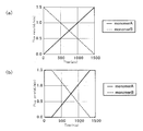
- the ratio of monomer A and monomer B is the ratio shown in FIG. The ratio changes continuously with time.
- the preliminary polymerization tube 7 is a stainless steel tube having an inner diameter of 5 mm. In order to set the residence time in the prepolymerization tube 7 to about 3 hours, the length of the prepolymerization tube 7 was set to 14 m.
- the temperature of the cylindrical container 12 was controlled at 70 ° C.
- the inner diameter of the cylindrical container 12 is 70 mm.
- the cylindrical container 12 is rotating (500 rpm). A total volume of about 2200 mL was injected over about 24 hours. Until 3 hours from the start of liquid feeding, the prepolymerized product from the prepolymerization tube 7 was not supplied into the cylindrical container 12. Three hours after the start of liquid feeding, the prepolymer was supplied into the cylindrical container 12 for the first time. Polymerization (70 ° C., 3 hours) was performed in the cylindrical container 12. Thereafter, a post-polymerization treatment at 120 ° C. for 3 hours was performed. Thereafter, cooling was gradually performed so as not to cause cracks due to heat shock or the like. That is, it was cooled to 70 ° C. over 2 hours.
- the glass cylindrical container 12 was taken out. Crushing was performed and the polymer was taken out. If the temperature at the time of crushing is too low, there is a risk of cracking of the polymer or spontaneous crushing during handling. When the temperature at the time of crushing is too high, the polymer is soft and the surface of the polymer may be damaged when the cylindrical container 12 is crushed.
- the refractive index distribution of this hollow rod is shown in FIG.
- the horizontal axis (X) in FIG. 4 is the distance in the direction (radial direction) from the outermost periphery to the innermost periphery of the hollow rod.
- the vertical axis in FIG. 4 is the refractive index.
- the solid line is the calculated value
- the ⁇ mark is the actually measured value.
- the refractive indexes of the outermost and innermost portions of the rod are different from the calculated values when the introduced mixed monomer is polymerized and deposited as prescribed.
- the diffusion mixture of monomers in the prepolymerization tube 7 and the cylindrical container 12 are different. This is considered to be the effect of diffusion within.
- a rod having a large refractive index difference ⁇ n was obtained.
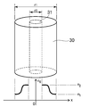
- the thinning (drawing) of the hollow rod 30 was performed.
- the apparatus used at this time is shown in FIG.
- the hollow portion 31 was drawn by a roller 33 while being decompressed and heated in a heating furnace 32.
- a gradient index plastic optical fiber was obtained.
- a monomer is injected into the hollow portion 31.
- the cylindrical container 12 was set up in the vertical direction, and the monomer A was injected into the hollow portion 31.
- post-polymerization was performed at 120 ° C. for 3 hours.
- the monomer A may be pre-polymerized in the hollow portion 31 of the hollow rod in the cylindrical container 12 that is erected in the vertical direction.
- Another method of manufacturing a rod that is also filled with a central portion is described. A cylindrical rod having a diameter slightly smaller than the diameter of the hollow portion 31 was polymerized with the monomer A alone, and the cylindrical rod was inserted into the hollow portion 31 to obtain a rod substantially filled with the central portion. .
- FIG. 6 is a graph of reaction time-polymerization rate when two types of monomers are used.
- PH-V -butyl 4,4-ditertiary butyl peroxyvalerate
- n-OM chain transfer agent for molecular weight adjustment
- FIG. 6 shows the polymerization rate when two monomers and two monomer mixtures (mixing ratio is 1: 1) are bulk polymerized at 70 ° C. in a test tube.
- the polymerization rate of the outlet semipolymer (preliminary polymer) retained for a certain time while being fed in the prepolymerization tube 7 maintained at 70 ° C. is shown in FIG.
- An increase in the polymerization rate can be estimated by an increase in the viscosity of the liquid. In either case, the viscosity of the liquid increases from about 2 (cP) in the monomer state to about 1000 (cP) after about 3 hours. It can be seen that the time point around 3 hours is the time when the polymerization rate called the gel effect increases.
- the present invention has been made paying attention to this phenomenon. That is, according to the apparatus of FIG. 1, it is possible to perform continuous liquid feeding in a closed system in which no foreign matter is mixed.
- the prepolymerization tube 7 polymerization of the monomer injected into the cylindrical container 12 does not progress so much for about 3 hours at the beginning of injection.
- the newly injected monomer already invades and mixes the semipolymer (preliminary polymer) injected into the cylindrical container 12.
- a rod having a desired refractive index cannot be obtained.
- the polymerization itself is difficult to proceed. If the injection volume is slowed down, productivity will decrease. Furthermore, monomer evaporation in the cylindrical container 12 cannot be ignored.
- the apparatus shown in FIG. 1 includes a prepolymerization tube in which prepolymerization is performed in front of a cylindrical container in which full-scale polymerization is performed.
- a polymerization treatment for example, a polymerization treatment (pretreatment) of about 1 to 4 hours (a polymerization rate of 10 to 50%) is performed, so that the polymerization rate in the cylindrical container is high.
- a polymerization rate of 10 to 50%
- the polymerization proceeds smoothly in sequence.
- the polymer is sequentially deposited. As a result, a rod having a distribution in which the refractive index smoothly and continuously changed was obtained.
- Example 1 The apparatus of FIG. 1 was used.
- MMA, PO-O (0.05%), PH-V (0.05%), and n-OM (0.25%) are placed in tank 1.
- 3FEMA, PO-O (0.05%), PH-V (0.05%), and n-OM (0.25%) are placed in tank 2.
- Monomers in the tanks 1 and 2 were sent to the mixing device 5 by the micropumps 3 and 4.
- the liquid feeding amount was 1.5 mL / min in total from the tanks 1 and 2.
- the change in the mixing ratio of the monomers is shown in FIG.
- the total liquid feeding amount was about 2250 mL (time: 25 hours).
- the monomer was thoroughly mixed by the static mixer 5.
- the mixed monomer was fed into a prepolymerization tube (a stainless tube having an inner diameter of 5 mm and a length of 14 m) 7 through a foreign matter removing device (a pore filter having a pore size of 0.2 ⁇ m) 8.
- the prepolymerization tube 7 is wound spirally.
- the condition of liquid feeding is monitored by a preliminary polymerization degree monitoring device (liquid feeding pressure gauge) 6.
- the monitoring pressure becomes higher than the reference value, the polymerization in the prepolymerization tube 7 proceeds too much, so that the amount of liquid fed can be increased. That is, the residence time in the prepolymerization tube 7 can be shortened.
- the polymerization in the prepolymerization tube 7 is delayed, so that the liquid feeding amount can be reduced. That is, the residence time in the prepolymerization tube 7 is increased.
- the residence time in the prepolymerization tube 7 was about 3 hours.
- the preliminary polymerization tube 7 is disposed in the water tank. The water in the water tank is maintained at 70 ° C. An ultrasonic device is disposed in the water tank. Ultrasonic vibration acts on the prepolymerization tube 7.
- the length of the pipe 11 is 1 m.
- the inner diameter of the pipe 11 is 5 mm.
- the pipe 11 is maintained at 70 ° C. by the tape heater.
- Dry nitrogen gas is supplied into the chamber 15 via a pore filter (pore diameter: 0.2 ⁇ m) 16.
- the cylindrical container 12 made of Pyrex glass has an outer diameter of 75 mm, an inner diameter of 70 mm, and a length of 600 mm. One end side is processed into a hemispherical shape. On the other end side, an injection port having an outer diameter of 10 mm, an inner diameter of 7 mm, and a length of 100 mm is provided.
- the cylindrical container 12 is carefully cleaned and dried with detergent water, an alkaline solution, steam cleaning, or the like. Oil and foreign matter are not attached. Prior to use, replacement with an inert gas (nitrogen gas) is performed.
- the cylindrical container 12 installed in the horizontal direction is rotating (500 rpm).
- the cylindrical container 12 is held at 70 ° C.
- prepolymerization (about 3 hours) was performed in the prepolymerization tube 7.
- the prepolymer obtained by prepolymerization in the prepolymerization tube 7 was supplied into the cylindrical container 12. Polymerization (3 hours) was carried out in the cylindrical container 12. The polymer adhered to the inner wall of the cylindrical container 12. This was followed by post-treatment (120 ° C., 3 hours).
- the rod taken out was cylindrical (see FIG. 3).
- the refractive index distribution of this rod was measured with a refractometer (Abbe refractometer NAR-3T manufactured by Atago Co., Ltd.). The result is shown in FIG.
- the refractive index of this hollow rod was 1.42 at the outermost periphery of the hollow rod and 1.49 at the innermost periphery of the hollow rod.
- the rod was thinned (drawn) with the apparatus shown in FIG.
- the hollow portion was depressurized (exhausted).
- the refractive index is low on the outer peripheral side and high on the inner peripheral side. Between the two, the refractive index changes continuously.
- the transmission loss (wavelength 550 nm) of this optical fiber was 160 dB / km.
- a He—Ne laser was incident from one end of 15 m. Even by appearance observation in a dark place, no bright spots due to foreign substances were observed.
- the rod was thinned (drawn) with the apparatus shown in FIG.
- the hollow portion was depressurized (exhausted).
- a plastic optical fiber (1 mm diameter) was obtained.
- the refractive index is low on the outer peripheral side and high on the inner peripheral side.
- the refractive index of this hollow rod was 1.42 on the outer surface and 1.49 on the inner surface. Between the two, the refractive index changes almost continuously.
- the transmission loss (wavelength 550 nm) of this optical fiber was 160 dB / km.
- a He—Ne laser was incident from one end of 15 m. Even by appearance observation in a dark place, no bright spots due to foreign substances were observed.
- Example 3 The rod obtained in Example 2 was erected. Monomers in the tank 2 were injected into the hollow portion. Prepolymerization (70 ° C., 6 hours) was performed. Thereafter, post-polymerization (120 ° C., 3 hours) was performed. This cylindrical rod was drawn with the apparatus of FIG. Thereby, an optical fiber equivalent to that of Example 2 was obtained.
- the flow rate of monomer A was set to 0.015 mL / min for 1 hour after the subsequent 9 hours of polymerization (no liquid feeding state).
- the flow rate of monomer A for the next hour was 0.030 mL / min.
- the flow rate of monomer A was increased to 1.5 mL / min in about 100 steps in an arithmetic progression.
- Others were performed according to Example 1.
- the polymerization was complete. That is, a cylindrical rod was obtained. However, compared with Example 1, it took about 10 times the manufacturing time. Productivity was bad.
- the refractive index distribution of the cylindrical rod of Comparative Example 2 was measured in the same manner as in Example 1. As a result, the result was almost the same as that shown in FIG.
- the rod of Comparative Example 2 was cut in the diameter direction and polished. This cut surface (polished surface) was observed. As a result, a pattern in which transmitted light was distorted in an annual ring shape was observed. This suggests that the refractive index distribution is discontinuous (step change).
- the rod of Example 1 was cut and polished in the same manner. This cut surface (polished surface) was observed. However, in this case, the pattern seen in Comparative Example 2 was not seen. This suggests that the refractive index profile is continuous.
Landscapes
- Engineering & Computer Science (AREA)
- Mechanical Engineering (AREA)
- Polymerisation Methods In General (AREA)
- Moulding By Coating Moulds (AREA)
Abstract
Δnが大きく、屈折率分布プロファイル形成の自由度が高く、製造時間が短縮でき、異物管理などが容易な屈折率分布型プラスチック製ロッドを提供することである。 容器と前記容器内に配置された原料供給管とを備えた装置が用いられてプラスチック製ロッドが製造される方法であって、前記ロッドを構成する重合性モノマの供給は、前記ロッド外周部側の屈折率は小さく、前記ロッド中心部側の屈折率は大きく、前記外周部と前記中心部との間の屈折率が略連続的に変化するように制御され、前記ロッド構成原料は、前記容器内に供給されるに先立って、予備重合される。
Description
本発明は屈折率分布型プラスチック製ロッドに関する。
ガラス製(又はプラスチック製)の光ファイバには、屈折率分布(Graded Index:GI)型光ファイバがある。前記GI型光ファイバは、通信装置や画像処理装置の分野において、広く、採用されている。プラスチック製のGI型光ファイバは、屈折率が異なる2種類以上の重合性モノマの重合により、製造されている。前記製造には下記技術が提案されている。
[反応性比利用法]
円筒型回転容器内に2種以上の単量体混合物が仕込まれる。比重差や反応性差が利用される。得られたロッドの外周部の屈折率と、中心部の屈折率とは、異なっている(特許文献1)。
円筒型回転容器内に2種以上の単量体混合物が仕込まれる。比重差や反応性差が利用される。得られたロッドの外周部の屈折率と、中心部の屈折率とは、異なっている(特許文献1)。
しかし、外周部の屈折率と中心部の屈折率との差が大きなロッドは、得られていない。
[拡散法]
重合体と単量体との混合物を押出ファイバ化しながら、外周から連続的に高屈折率の単量体成分を揮発させる方法(特許文献2)が有る。円柱形状のPMMA製ゲルの外周部に低屈折率単量体を拡散させる方法(特許文献3)が有る。
重合体と単量体との混合物を押出ファイバ化しながら、外周から連続的に高屈折率の単量体成分を揮発させる方法(特許文献2)が有る。円柱形状のPMMA製ゲルの外周部に低屈折率単量体を拡散させる方法(特許文献3)が有る。
これらの方法でも、外周部の屈折率と中心部の屈折率との差が大きなロッドは、得られていない。
低屈折率の中空重合体の中心部に、重合後に高屈折率となるモノマを導入・拡散する方法(特許文献4)が有る。
この方法は、モノマ分離が可能である。しかし、工程が連続的でなく、煩雑である。更には、光ファイバでの重要問題(異物混入)が残っている。
[順次堆積法]
円筒回転容器(石英管)内に2種以上のモノマの混合比を変えながら供給・積層する方法(特許文献1,5)が有る。回転する円筒重合体(クラッド)の内側に、順次、モノマ混合比を変えながら供給して積層する方法(特許文献6)が有る。
円筒回転容器(石英管)内に2種以上のモノマの混合比を変えながら供給・積層する方法(特許文献1,5)が有る。回転する円筒重合体(クラッド)の内側に、順次、モノマ混合比を変えながら供給して積層する方法(特許文献6)が有る。
しかし、一般に、重合速度が遅い。更に、新たに注入したモノマが、既に硬化している層を溶解する。この為、屈折率が異なるモノマが層状に固定・堆積し難い。この問題を解決する為、注入速度を遅くすることが考えられた。しかし、新たに注入したモノマが、既に重合した堆積層に浸み込む。この結果、屈折率の分布特性が悪い。かつ、生産性が悪い。
透明プラスチック製パイプが、円筒回転反応容器として、用いられる。回転する前記透明プラスチック製パイプの内側に、屈折率調整剤の組成を変化させながら、重合性モノマが順次注入される。重合堆積後に、プラスチック製パイプが延伸して線引き(細線化)される方法(特許文献6)が有る。
しかし、前記プラスチック製パイプを、重合温度まで昇温させながら、長時間、回転させるには、機械的な強度面において、安定運転が困難である。更に、屈折率調整剤は重合したポリマと結合していない。この為、長期的に見て、特性が不安定である。しかも、大きな屈折率差が得られ難い。
前記[反応性比利用法]及び前記[拡散法]では、大きな屈折率差Δnを持つロッドが得られなかった。Δnは0.03以下であった。この為、開口数NAが大きな(明るい)ファイバや、広開口数のロッドレンズは得られない。更に、屈折率分布は拡散分布による。この為、屈折率分布は放物線からずれている。そのような屈折率分布は好ましいとは言えない。
前記[順次堆積法]では、大きな屈折率差Δnを持つロッドが得られる。屈折率分布プロファイルの自由形成が実現できる。しかし、複数種の単量体組成を変化させながら連続注入しても、重合完了前に、先に重合した層を単量体が溶解する。この為、重合物は均一混合してしまう。分布付けが出来ないことから、断続的に注入し、1層ずつ、重合を完結して積層する方法が取られて来た。連続的な分布形成を達成する為には、20層以上に段数を多くしなければならない。個々の重合を完結させる為、時間が掛る。後注入を行なう為、管理が煩雑であった。
従って、本発明が解決しようとする課題は、Δnが大きく、屈折率分布プロファイル形成の自由度が高く、製造時間が短縮でき、異物管理などが容易な屈折率分布型プラスチック製ロッドを提供することである。
本発明は、
容器と、前記容器内に配置された原料供給管とを備えた装置が用いられてプラスチック製ロッドが製造される方法であって、
前記プラスチック製ロッドを構成する重合性モノマの供給は、
前記プラスチック製ロッドの外周部側の屈折率は小さく、前記プラスチック製ロッドの中心部側の屈折率は大きく、前記外周部と前記中心部との間の屈折率が略連続的に変化するように制御され、
前記プラスチック製ロッドの構成原料は、前記容器内に供給されるに先立って、予備重合される
ことを特徴とする屈折率分布型プラスチック製ロッドの製造方法を提案する。
容器と、前記容器内に配置された原料供給管とを備えた装置が用いられてプラスチック製ロッドが製造される方法であって、
前記プラスチック製ロッドを構成する重合性モノマの供給は、
前記プラスチック製ロッドの外周部側の屈折率は小さく、前記プラスチック製ロッドの中心部側の屈折率は大きく、前記外周部と前記中心部との間の屈折率が略連続的に変化するように制御され、
前記プラスチック製ロッドの構成原料は、前記容器内に供給されるに先立って、予備重合される
ことを特徴とする屈折率分布型プラスチック製ロッドの製造方法を提案する。
本発明は、
円筒型容器と、前記円筒型容器の中心軸芯位置に配置された原料供給管とを備えた装置が用いられてプラスチック製ロッドが製造される方法であって、
前記プラスチック製ロッドの構成原料として、屈折率が異なる2種類以上の重合性モノマが、少なくとも、用いられ、
前記プラスチック製ロッドの構成原料は、前記原料供給管から、前記円筒型容器内に、供給され、
前記円筒型容器は、前記原料供給管に対して、相対的に、回転し、
前記プラスチック製ロッドを構成する前記重合性モノマの供給は、
前記プラスチック製ロッドの外周部側の屈折率は小さく、前記プラスチック製ロッドの中心部側の屈折率は大きく、前記外周部と前記中心部との間の屈折率が連続的に変化するように制御され、
前記プラスチック製ロッドの構成原料は、前記円筒型容器内に供給されるに先立って、予備重合される
ことを特徴とする屈折率分布型プラスチック製ロッドの製造方法を提案する。
円筒型容器と、前記円筒型容器の中心軸芯位置に配置された原料供給管とを備えた装置が用いられてプラスチック製ロッドが製造される方法であって、
前記プラスチック製ロッドの構成原料として、屈折率が異なる2種類以上の重合性モノマが、少なくとも、用いられ、
前記プラスチック製ロッドの構成原料は、前記原料供給管から、前記円筒型容器内に、供給され、
前記円筒型容器は、前記原料供給管に対して、相対的に、回転し、
前記プラスチック製ロッドを構成する前記重合性モノマの供給は、
前記プラスチック製ロッドの外周部側の屈折率は小さく、前記プラスチック製ロッドの中心部側の屈折率は大きく、前記外周部と前記中心部との間の屈折率が連続的に変化するように制御され、
前記プラスチック製ロッドの構成原料は、前記円筒型容器内に供給されるに先立って、予備重合される
ことを特徴とする屈折率分布型プラスチック製ロッドの製造方法を提案する。
本発明は、前記屈折率分布型プラスチック製ロッドの製造方法であって、前記予備重合は、予備重合管内において、行われ、前記予備重合管は、前記容器内に配置された前記原料供給管に接続されていることを特徴とする屈折率分布型プラスチック製ロッドの製造方法を提案する。
本発明は、前記屈折率分布型プラスチック製ロッドの製造方法であって、前記容器内に供給された予備重合物は、前記容器内壁に、順に、付着し、前記付着終了前後の時点において、重合が終了し、前記容器内壁側の屈折率が小さく、前記容器中心軸芯側の屈折率が大きく、その間で屈折率が連続的に変化している屈折率分布型プラスチック製ロッドが得られることを特徴とする屈折率分布型プラスチック製ロッドの製造方法を提案する。
本発明は、前記屈折率分布型プラスチック製ロッドの製造方法であって、前記重合性モノマの供給・制御は、前記重合性モノマの配合割合の制御であることを特徴とする屈折率分布型プラスチック製ロッドの製造方法を提案する。
本発明は、前記屈折率分布型プラスチック製ロッドの製造方法であって、前記容器は水平方向に配置されていることを特徴とする屈折率分布型プラスチック製ロッドの製造方法を提案する。
本発明は、前記屈折率分布型プラスチック製ロッドの製造方法であって、前記円筒型容器の円筒壁面がガラス製であることを特徴とする屈折率分布型プラスチック製ロッドの製造方法を提案する。
本発明は、前記屈折率分布型プラスチック製ロッドの製造方法であって、前記予備重合の重合度がモニタされ、その重合度が制御されることを特徴とする屈折率分布型プラスチック製ロッドの製造方法を提案する。
本発明は、前記屈折率分布型プラスチック製ロッドの製造方法であって、前記予備重合が行われる管の内壁に前記予備重合物が付着して前記予備重合物の移動の妨害が防止されることを特徴とする屈折率分布型プラスチック製ロッドの製造方法を提案する。
本発明は、前記屈折率分布型プラスチック製ロッドの製造方法であって、供給された2種類以上の重合性モノマは、予備重合の前において、混合されることを特徴とする屈折率分布型プラスチック製ロッドの製造方法を提案する。
本発明は、前記屈折率分布型プラスチック製ロッドの製造方法であって、前記プラスチック製ロッドの構成原料は連続的に供給されることを特徴とする屈折率分布型プラスチック製ロッドの製造方法を提案する。
本発明は、
前記屈折率分布型プラスチック製ロッドの製造方法で得られた屈折率分布型プラスチック製ロッドが、細線化される
ことを特徴とする屈折率分布型光ファイバの製造方法を提案する。
前記屈折率分布型プラスチック製ロッドの製造方法で得られた屈折率分布型プラスチック製ロッドが、細線化される
ことを特徴とする屈折率分布型光ファイバの製造方法を提案する。
大きな屈折率差が有る屈折率分布型プラスチック製ロッドが得られる。
前記屈折率分布型プラスチック製ロッドを基にして、開口数NAが大きな光ファイバが得られる。短焦点のロッドレンズが得られる。
第1の発明は屈折率分布型プラスチック製ロッドの製造方法である。以下、実施形態が説明される。前記方法は、容器と原料供給管とを備えた装置が用いられる。前記原料供給管は前記容器内に配置されている。前記容器は、例えば円筒型容器である。前記原料供給管は、例えば前記容器の中心軸芯位置に配置されている。前記容器は、好ましくは、その長手方向が水平方向であるように配置されている。例えば、前記円筒型容器の軸芯方向が水平方向であるように、前記円筒型容器は配置されている。前記容器は、その壁面(周壁面(例えば、円筒状壁面)が、好ましくは、ガラス製である。勿論、その他の部位もガラス製であっても良い。前記容器がガラスで出来ていると、重合終了後に、ガラス製容器を破砕することによって、前記屈折率分布型プラスチック製ロッドが簡単に得られる。前記プラスチック製ロッドの構成原料として、好ましくは、屈折率が異なる2種類以上の重合性モノマが用いられる。前記重合性モノマの他にも、必要に応じて、各種の成分が用いられる。例えば、重合開始剤などである。前記プラスチック製ロッドの構成原料は、前記原料供給管から、前記容器内に、供給される。前記円筒型容器は、前記原料供給管に対して、相対的に、回転する。例えば、前記円筒型容器が回転する。前記プラスチック製ロッドを構成する前記重合性モノマの供給は次のように制御される。前記プラスチック製ロッドの外周部側の屈折率は小さく、前記プラスチック製ロッドの中心部側の屈折率は大きく、前記外周部と前記中心部との間の屈折率が連続的(実質、連続:略連続)に変化するように制御される。前記屈折率分布が形成されるように、例えば前記重合性モノマの配合割合が制御される。「連続的変化」とは次の意味である。本発明にあっては、[屈折率の差]≦[n2(最大屈折率)-n1(最小屈折率)]×0.01の場合、「屈折率が同じ(実質、同一:略同一)」と見做される。従って、{[X1+ΔX(ΔX>0)において、ΔXが0に近付いた場合の屈折率の値]-[X1-ΔX(ΔX>0)において、ΔXが0に近付いた場合の屈折率の値]}≦(n2-n1)×0.01の場合、点(X1)において、屈折率変化は連続的であると見做される。屈折率変化が階段的変化(不連続的変化)であると、その変化する位置において、Δn/ΔXは極めて大きな値(例えば、∞)を取る。前記プラスチック製ロッドの構成原料は、前記円筒型容器内に供給されるに先立って、予備重合される。
前記予備重合は、好ましくは、予備重合管内において、行われる。前記予備重合は、好ましくは、温度制御された予備重合管内において、行われる。前記予備重合管は、前記容器内に配置された前記原料供給管に接続されている。前記予備重合管の容積は、例えば前記容器(例えば、円筒型容器)の容積の1%以上100%以下である。
前記容器内に供給された予備重合物は、好ましくは、前記容器内壁に、順に、付着する。前記付着終了前後の時点において、重合が終了する。
前記予備重合において、好ましくは、予備重合度がモニタされる。例えば、予備重合管の適宜な個所(例えば、入口部)に、予備重合度モニタ手段(例えば、注入圧力計)が設けられる。前記モニタに基づいて、予備重合度は制御される。
前記予備重合に前以って、好ましくは、異物除去が行われる。例えば、予備重合管の適宜な個所(例えば、入口部)に、異物除去手段(例えば、ポアフィルタ)が設けられる。これによって、予備重合物中への異物混入が防止される。
前記予備重合において、好ましくは、前記予備重合が行われる管の内壁に前記予備重合物が付着して前記予備重合物の移動の妨害が、防止される。例えば、予備重合管に超音波振動が作用させられる。これによって、前記予備重合物が前記予備重合管の内壁に付着し難くなる。
供給された2種類以上の重合性モノマは、好ましくは、予備重合の前において、混合される。例えば、スタティックミキサによって、前記重合性モノマの混合が行われる。モノマA供給源1からの供給路とモノマB供給源2からの供給路との合流部に、例えばスタティックミキサが配置されている。これによって、前記予備重合前におけるモノマ混合が十分に行われる。
好ましくは、前記円筒容器の内側面に重合硬化層が形成され、中心部に中空部が形成された後で、前記円筒容器の注入口が上方となるように垂直に設置され、前記中空部内壁と同じ組成のモノマが前記注入口から充填され、重合が完結後に、前記円筒容器が破砕され、重合体が取り出される。
図1は、前記屈折率分布型プラスチック製ロッドの製造装置の概略図である。
図1中、1,2はタンクである。タンク1,2には、ラジカル重合性モノマが充填されている。モノマは、例えばメチルメタクリレート系モノマ、塩素(又はフッ素)含有メチルメタクリレート系モノマ、スチレン系モノマなどである。屈折率差が大きなロッドが構成されるモノマの組み合わせが、適宜、選択される。
3,4はマイクロポンブである。マイクロポンプ3,4は、コンピュータ制御が行われる。これによって、流量制御(供給量制御)が高精度で行われる。タンク1,2内のモノマが、マイクロポンプ3,4によって、混合装置5に、高精度で、送られる。
混合装置5において、少なくとも2種類のモノマが完全に混合される。混合装置5は、例えば一定容量のダンパ装置(又はスタティックミキサ)である。2種類のモノマは、単に、合流したのみでは、混じり難い。特に、流量が少ない場合、合流しても、層流となる場合が多い。従って、混合装置5が必要である。十分な混合が行われなかった場合は、反応性が異なるモノマが分離して流れる。反応が速いモノマの重合が先に進み、粘度が増大する。これが管壁に付着する。不均一で不安定な現象が起こる。過度に大きな容量のダンパ装置が用いられると、ダンパ装置内での混合の影響が大きい。モノマの組成比率(配合割合)を変化させる場合、その効果が半減する。従って、容量が小さなスタティックミキサの採用が好ましい。前記ダンパ装置(又はスタティックミキサ)の容積は、例えば前記円筒型容器の容積の0.1%以上10%以下である。この範囲より小さいと、混合装置5の効果が不十分となり、モノマが混じり難い。
6は予備重合度モニタ装置である。予備重合度モニタ装置6は、予備重合管(例えば、細径の管)7内における予備重合度をモニタリングする。予備重合度モニタ装置6は、例えば送液圧力計である。予備重合度モニタ装置6は、予備重合管7の入口部に設置されている。予備重合度モニタ装置6が予備重合管7の出口部に設置されていると、密閉系で簡便に常時監視することが困難である。予備重合度は、例えば重合率あるいは粘度などを測定することで推定できる。予備重合管7内で重合が進み、粘度が増大することに注目すれば、予備重合管7の入口部での圧力変化をモニタリングすることによって、予備重合の程度がチェックできる。一定流量でモノマが送液された場合、何らかの要因で定常状態から反応が進み、粘度が増大した場合、送液圧力の上昇が把握される。流量を増やして、予備重合管7内での滞留時間を短縮したり、予備重合管7の保持温度を低下させる等の対策が取れる。予備重合が進まない場合には、送液粘度が低下するので、送液流量を下げて滞留時間を長くしたり、温度上昇を図る等の対策が取られる。予備重合度モニタ装置によるモニタリング結果により、予備重合度が所定の範囲となるように対策が取られる。
予備重合管7は、径が小さく、長さが長い管である。前記管の長さLと、前記管の内径dとは、例えば次の寸法である。L(mm)=1000~50000。d(mm)=1~10。L/d=1000~5000。管の内径と長さによる管内容量と送液流量は、管内に滞留させる滞留時間で好適に設定される。L/dが1000より小さいと、拡散混合の為に、所望の組成分布が得られ難くなる。L/dが5000より大きいと、送液抵抗が大きくなる。詰まりの懸念が有る。
8は異物除去装置である。異物除去装置8は、予備重合管7の入口部に設置されている。異物除去装置8が予備重合管7の出口部に設置されると、送液抵抗が増大するので、好ましくない。更に、予備重合物への異物混入が防止され難い。異物除去装置8は、例えばポアフィルタ(又はメンブレンフィルタ)である。
9は温度制御装置である。温度制御装置9は、例えば恒温槽(熱媒体は、例えば空気、水、油など)である。温度制御装置9は予備重合管7の温度を制御する。予備重合時の温度が温度制御装置9によって制御される。予備重合管7全体で均一に温度制御されても良く、部分的に温度管理されても良い。例えば、前半部での温度、中間部での温度、後半部での温度が、各々、別々に、制御されても良い。
10は堆積物除去装置である。重合物が、予備重合管7の内壁面に、付着堆積する懸念が有る。重合物が予備重合管7の内壁面に付着堆積すると、送液圧力が高くなる。詰まりが起きる恐れが有る。予備重合管7の実効容積が減少するので、滞留時間が減少する。管壁堆積物がモノマに洗われ、屈折率分布付けが阻害される等の弊害が懸念される。これは運転の定常性や安定性に好ましくない。これを防ぐ為、堆積物除去装置10が設けられた。本装置10は、例えば超音波振動装置である。超音波振動が予備重合管7に作用すると、重合物が予備重合管7内壁に付着し難い。例えば、超音波装置を備えた水槽中に予備重合管7が配置されることで良い。
11は、予備重合管7と円筒型容器12とを接続する配管である。配管11の径が予備重合管7の径より小さいと、送液抵抗が増大し、好ましくない。逆に、大きくなると、配管11内での滞留時間が増えたり、拡散混合が起きるので、好ましくない。従って、配管11の径と予備重合管7の径とは同程度が好ましい。配管11の長さも短いことが好ましい。例えば、2m以下が好ましい。テープヒータ等によって、配管11は保温されていることが好ましい。温度が低下すると、粘度が増大し、送液抵抗が大きくなる。しかし、温度が過度に高くなると、重合が過度に進む恐れがある。予備重合管7の温度と配管11の温度とは同程度であることが好ましい。
円筒型容器12内には、配管11を介して、予備重合物(予備重合体)が注入される。特に、予備重合物は、連続的に、注入される。配管11先端の注入管13から、予備重合物が、円筒型容器12内に注入される。特に、予備重合物は、円筒型容器12の長さ方向(図1では、左右方向)の略中央位置において、滴下される。円筒型容器12は回転ホルダ14で保持されている。円筒型容器12は回転駆動される。円筒型容器12内への注入管13の導入口部は、室15内に、配置されている。フィルタ16を経由して、常時、供給された不活性ガス(例えば、窒素ガス)が、室15に、充満している。これによって、円筒型容器12内への酸素侵入が防止される。異物混入も防止される。
円筒型容器12はガラス製である。特に、パイレックスガラス製である。片端は半球状に加工されている。他端は、細い注入口が設けられたガラスアンプルである。円筒型容器12の内径は、例えば50mm~200mmである。円筒型容器12の長さは、例えば500mm~2000mmである。前記内径が小さ過ぎると、又、前記長さが短すぎると、生産性に劣る。前記内径が大き過ぎると、重合物の加熱延伸工程において、重合物の半径方向中心部と外周部とを均一に加熱することが困難になる。この為、延伸が難しくなる。前記長さが長くなり過ぎると、取り扱いが困難になる。
円筒型容器12の内壁は、洗剤水、アルカリ溶液、水蒸気洗浄などによって洗浄されている。乾燥後、不活性ガス置換が行われている。油分や異物が完全に除去されている。
水平方向に設置された円筒型容器12は回転駆動される。例えば、500rpmで回転している。重合開始当初の回転数は小さくても良い。しかし、円筒型容器12内壁に重合物が堆積するにつれて、回転数を増大させることが好ましい。表面の遠心力が小さくなり、注入したモノマが内壁の上面から自重で落下する恐れが有るからである。前記回転数は、注入したモノマが内壁の上面から自重で落下しない下記式が満足されれば良い。
mrω2>mg
[m(kg)=モノマの質量、r(m)=回転中心から内壁に堆積した重合物までの内径の半値、ω(rad/sec)=回転角速度、g(m/sec2)=重力加速度]
[m(kg)=モノマの質量、r(m)=回転中心から内壁に堆積した重合物までの内径の半値、ω(rad/sec)=回転角速度、g(m/sec2)=重力加速度]
例えば、前記内壁に重合物が積層し、内径が10(mm)、即ち、r=0.005(m)となっても、回転数が500(rpm)であれば、ω=52.3(rad/sec)であり、モノマが内壁面から自重で落下しない。
円筒型容器12は槽内に設置されている。前記槽内には、所定温度に制御された不活性ガス(例えば、窒素ガス)が供給されている。これによって、円筒型容器12は、所定温度に保持されている。ガラス製の円筒型容器12は槽内に設置されているから、円筒型容器12が運転中に破砕しても、安全性が確保されている。円筒型容器12内は非接触型の赤外線温度計17でモニタリングされている。重合の過度な進行等の異常事態は、前記モニタリングによって、発見できる。
例えば、図1の装置が用いられた。モノマAとモノマBとが、コンピュータ制御されたマイクロポンプ3,4で、総量1.5mL/分となるように送液された。モノマAが高屈折率のモノマ、モノマBが低屈折率のモノマである。モノマAとモノマBとの割合は、図2(a)に示される割合である。前記割合は、時間によって、連続的に、変化している。予備重合管7は内径5mmのステンレス管である。予備重合管7内での滞留時間を約3時間とする為、予備重合管7の長さが14mに設定された。円筒型容器12の温度は70℃に制御された。円筒型容器12の内径は70mmである。円筒型容器12は回転(500rpm)している。約24時間の送液で総量約2200mLが注入された。送液開始3時間までは、予備重合管7からの予備重合物は円筒型容器12内に供給されなかった。送液開始してから3時間後に、予備重合物は、初めて、円筒型容器12内に供給された。円筒型容器12内において、重合(70℃、3時間)が行われた。この後、120℃での3時間の後重合処理が行われた。この後、ヒートショックなどで亀裂などが起きないように、冷却が徐々に行われた。すなわち、2時間掛けて、70℃まで冷却された。この後、ガラス製の円筒型容器12が取り出された。破砕が行われ、重合物が取り出された。破砕時の温度が低すぎた場合、重合物の割れや、取扱い中の自然破砕の恐れが有る。破砕時の温度が高すぎた場合、重合物が柔らかく、円筒型容器12の破砕時に、重合物表面が傷付く恐れが有る。
連続注入によって得られた重合物が図3に示される。中空ロッド(外径r1=70mm、内径r2=15mm)が得られた。この中空ロッドの屈折率分布が、図4(a)に示される。図4の横軸(X)は、中空ロッドの最外周部から最内周部への方向(半径方向)における距離である。図4の縦軸は屈折率である。図4中、実線は計算値、〇印は実測値である。ロッドの最外周部および最内周部の屈折率が、導入された混合モノマが所定通り重合堆積した場合の計算値と異なるのは、予備重合管7内におけるモノマの拡散混合や円筒型容器12内での拡散の影響と考えられる。しかし、大きな屈折率差Δnを有するロッドが得られた。
モノマAとモノマBとの割合が図2(b)に示される割合であると、図4(b)の屈折率分布のロッドが得られた。
前記中空ロッド30の細線化(線引き)が行われた。この時に用いられた装置が図5に示される。中空部31は減圧、かつ、加熱炉32にて加熱されながら、ローラ33によって、線引きが行われた。これによって、屈折率分布型プラスチック光ファイバが得られた。
中空状ロッドでなく、中心部も充填されたロッドが必要な場合には、中空部31にモノマが注入される。円筒型容器12内での重合が完結した後で、円筒型容器12が垂直方向に立てられ、中空部31にモノマAが注入された。70℃にて6時間の重合が行われた後、120℃にて3時間の後重合が行われた。これにより、中空状でない屈折率分布型ロッドが得られた。この後、線引きが行われた。垂直方向に立てられた円筒型容器12内の中空状ロッドの中空部31内には、前記モノマAの代わりに、前記モノマAが予備重合されたものであっても良い。
中心部も充填されたロッドの別の製造方法が説明される。中空部31の直径より僅かに小さな直径の円柱状ロッドをモノマAのみで重合し、この円柱状ロッドを中空部31へ挿入することによって、実質的に中心部も充填されたロッドが得られた。
中心部も充填されたロッドの別の製造方法が説明される。中空部31の直径より僅かに小さな直径の円柱状ロッドをモノマAのみで重合し、この円柱状ロッドを中空部31へ挿入することによって、実質的に中心部も充填されたロッドが得られた。
図6は、2種類のモノマが用いられた場合における反応時間-重合率のグラフである。
前記モノマは、メチルメタクリレート(MMA:重合時の屈折率=1.49)と、2,2,2-トリフルオロエチルメタクリレート(3FEMA:重合時の屈折率=1.42)である。更に、前記モノマ合計量に対し、0.05%の1,1,3,3-テトラメチルブチルパーオキシ2-エチルヘキサノエート(PO-O:重合開始剤)と、0.05%のn-ブチル4,4-ジターシャリブチルパーオキシ吉草酸エステル(PH-V)と、0.25%のn-オクチルメルカプタン(n-OM:分子量調整用の連鎖移動剤)とが用いられた。
2種のモノマ、及び2種のモノマ混合物(混合割合は1:1)が、試験管内において、70℃で、塊状重合した場合の重合率が、図6に示される。図1の装置において、70℃に保持された予備重合管7内で送液しながら一定時間滞留させた出口の半重合体(予備重合体)の重合率が、図6に示される。重合率の増加は、液の粘度の増加で推定できる。何れも、約3時間後から、液の粘度は、モノマ状態の2(cP)から1000(cP)程度まで増加している。3時間前後の時点が、ゲル効果と呼ばれる重合速度が速まる時期であることが判る。本発明はこの現象に着目して成されたものである。すなわち、図1の装置によれば、異物混入がない密閉系で、しかも連続的な送液が可能となる。予備重合管7における予備重合工程が無い場合、円筒型容器12内に注入されたモノマは、注入初期の3時間程度の間は重合が余り進まない。新しく注入されたモノマが、既に、円筒型容器12内に注入された半重合物(予備重合物)を侵し、混合してしまう。この結果、所望の屈折率のロッドが得られない。かつ、重合自体が進行し難い。注入量を遅くすると、生産性が落ちる。更には、円筒型容器12内でのモノマ蒸発が無視できない。所望の屈折率分布のロッドが得られない。このようなことから、予備重合管7における予備重合工程が無い場合、一定量のモノマを注入しては重合を繰り返す、多段重合とせざるを得ない。これでは、生産性が悪い。しかも、屈折率が、連続した、かつ、なだらかな分布のロッドが得られない。図1の装置は、本格的な重合が行われる円筒型容器の前に、予備重合が行われる予備重合管を具備している。前記予備重合管内で、例えば1~4時間程度(重合率が10~50%)の重合処理(前処理)が行われることによって、前記円筒型容器内における重合速度は速い。この結果、重合が進み、前記円筒型容器内壁に付着した重合物がモノマで侵されることも少ない。重合は、順次、スムーズに進む。そして、重合物は、順次、堆積する。この結果、屈折率が、滑らかに、連続変化した分布のロッドが得られた。
以下、具体的な実施例が挙げられる。但し、本発明は以下の実施例のみに限定されない。本発明の特長が大きく損なわれない限り、各種の変形例や応用例も本発明に含まれる。
[実施例1]
図1の装置が用いられた。
図1の装置が用いられた。
MMAと、PO-O(0.05%)と、PH-V(0.05%)と、n-OM(0.25%)とが、タンク1に、入れられている。3FEMAと、PO-O(0.05%)と、PH-V(0.05%)と、n-OM(0.25%)とが、タンク2に、入れられている。前記タンク1,2のモノマが、マイクロポンプ3,4によって、混合装置5に、送られた。送液量は、タンク1,2からの合計量で、1.5mL/分であった。前記モノマの混合割合の変化が図2(a)に示される。総送液量は約2250mL(時間:25時間)であった。前記モノマは、スタティックミキサ5によって、完全に、混合された。
混合モノマは、異物除去装置(0.2μm孔径のポアフィルタ)8を経て、予備重合管(内径5mmで長さ14mのステンレス管)7内に送り込まれた。予備重合管7は螺旋状に巻かれている。送液具合は、予備重合度モニタ装置(送液圧力計)6によって、モニタリングされている。モニタリング圧力が基準値よりも高くなると、予備重合管7内での重合が進行し過ぎなので、送液量の増加が図られる。すなわち、予備重合管7内における滞留時間の短縮が図られる。モニタリング圧力が基準値よりも低くなると、予備重合管7内での重合が遅れているので、送液量の減少が図られる。すなわち、予備重合管7内における滞留時間の増加が図られる。予備重合管7内における滞留時間は約3時間であった。予備重合管7は、水槽内に、配置されている。前記水槽内の水は70℃に保持されている。前記水槽には超音波装置が配置されている。予備重合管7には超音波振動が作用している。
配管11の長さは1mである。配管11の内径は5mmである。テープヒータによって、配管11は70℃に保持されている。
乾燥窒素ガスが、ポアフィルタ(孔径:0.2μm)16を経由して、室15内に供給されている。
パイレックスガラス製の円筒型容器12は、外径75mm、内径70mm、長さ600mmである。一端側は半球状に加工されている。他端側は、外径10mm、内径7mm、長さ100mmの注入口が設けられている。円筒型容器12は、洗剤水、アルカリ溶液、水蒸気洗浄などによって、注意深く、洗浄・乾燥されている。油分や異物は付着していない。使用に先立って、不活性ガス(窒素ガス)による置換処理が行われている。
水平方向に設置された円筒型容器12は、回転(500rpm)している。
円筒型容器12は70℃に保持されている。
前記予備重合管7内において、先ず、予備重合(約3時間)が行われた。
前記予備重合管7内で予備重合して得られた予備重合物が、円筒型容器12内に、供給された。円筒型容器12内において、重合(3時間)が行われた。重合物は、円筒型容器12内壁に、付着した。この後、後処理(120℃,3時間)が行われた。
その後、70℃まで、徐々に(2時間掛けて)、冷却された。この後、円筒型容器12が取り出され、円筒型容器12は破砕された。そして、重合物(ロッド)が取り出された。
取り出されたロッドは円筒形状(図3参照)であった。外径r1=70mm、内径r2=15mmであった。このロッドの屈折率分布が、屈折率計(株式会社アタゴ社製 アッベ屈折率計NAR-3T)で計測された。その結果が図4(a)に示される。この中空ロッドの屈折率は、中空ロッドの最外周部が1.42、中空ロッドの最内周部が1.49であった。
前記ロッドが、図5の装置で、細線化(線引き)された。中空部内は減圧(排気)された。この結果、1mm径のプラスチック製光ファイバが得られた。屈折率は、外周側が低く、内周側が高い。両者の間で、屈折率は、連続的に、変化している。この光ファイバの伝送損失(波長550nm)は160dB/kmであった。15mの片端から、He-Neレーザが入射された。暗所での外観観察によっても、異物による輝点は認められなかった。
[実施例2]
実施例1において、送液パターンが、図2(a)から図2(b)に変更された以外は、実施例1に準じて行われた。中空ロッド(外径r1=70mm、内径r2=15mm)が得られた。本実施例で得られたロッドの屈折率分布が、図4(b)に示される。送液開始の初期時には、モノマはタンク2のみから送液された。送液終了の終期時には、モノマはタンク1のみから送液された。従って、ロッドの外周部や内周部は各々の単一モノマのみで構成されている。
実施例1において、送液パターンが、図2(a)から図2(b)に変更された以外は、実施例1に準じて行われた。中空ロッド(外径r1=70mm、内径r2=15mm)が得られた。本実施例で得られたロッドの屈折率分布が、図4(b)に示される。送液開始の初期時には、モノマはタンク2のみから送液された。送液終了の終期時には、モノマはタンク1のみから送液された。従って、ロッドの外周部や内周部は各々の単一モノマのみで構成されている。
前記ロッドが、図5の装置で、細線化(線引き)された。中空部内は減圧(排気)された。この結果、プラスチック製光ファイバ(1mm径)が得られた。屈折率は、外周側が低く、内周側が高い。この中空ロッドの屈折率は、外表面が1.42、内表面が1.49であった。両者の間で、屈折率は、ほぼ、連続的に、変化している。この光ファイバの伝送損失(波長550nm)は160dB/kmであった。15mの片端から、He-Neレーザが入射された。暗所での外観観察によっても、異物による輝点は認められなかった。
[実施例3]
実施例2で得たロッドが立てられた。中空部内に、タンク2内のモノマが注入された。前重合(70℃,6時間)が行われた。この後、後重合(120℃,3時間)が行われた。この円柱状ロッドが、図5の装置で、線引きが行われた。これによって、実施例2と同等な光ファイバが得られた。
実施例2で得たロッドが立てられた。中空部内に、タンク2内のモノマが注入された。前重合(70℃,6時間)が行われた。この後、後重合(120℃,3時間)が行われた。この円柱状ロッドが、図5の装置で、線引きが行われた。これによって、実施例2と同等な光ファイバが得られた。
[実施例4]
図1の装置からスタティックミキサ5が取り外された装置が用いられた。実施例1に準じて行われた。中空ロッド(外径r1=70mm、内径r2=20mm)が得られた。この中空ロッドの屈折率は、外表面が1.42、内表面が1.48であった。
図1の装置からスタティックミキサ5が取り外された装置が用いられた。実施例1に準じて行われた。中空ロッド(外径r1=70mm、内径r2=20mm)が得られた。この中空ロッドの屈折率は、外表面が1.42、内表面が1.48であった。
[実施例5]
図1の装置から超音波振動装置10が取り外された装置が用いられた。実施例1に準じて行われた。本実施例では、徐々に、送液圧力が増大した。15時間後には、管詰まりが発生した。従って、15時間で終了した。中空ロッド(外径r1=70mm、内径r2=50mm)が得られた。この中空ロッドの屈折率は、外表面が1.42、内表面が1.46であった。
図1の装置から超音波振動装置10が取り外された装置が用いられた。実施例1に準じて行われた。本実施例では、徐々に、送液圧力が増大した。15時間後には、管詰まりが発生した。従って、15時間で終了した。中空ロッド(外径r1=70mm、内径r2=50mm)が得られた。この中空ロッドの屈折率は、外表面が1.42、内表面が1.46であった。
[比較例1]
図1の装置から予備重合管7が取り外された装置が用いられた。実施例1に準じて行われた。5時間経過後において、円筒型容器12の回転が停止させられた。重合状況の確認が行われた。モノマが下方に溜まっており、重合が殆ど進行してないことが判った。
図1の装置から予備重合管7が取り外された装置が用いられた。実施例1に準じて行われた。5時間経過後において、円筒型容器12の回転が停止させられた。重合状況の確認が行われた。モノマが下方に溜まっており、重合が殆ど進行してないことが判った。
[比較例2]
図1の装置から予備重合管7が取り外された装置が用いられた。マイクロポンプ3,4によって、モノマが混合装置5に送られた。1時間の送液(送液量は、タンク1,2からの合計量で、1.5mL/分)が行われた。この後、9時間に亘る重合工程(この工程では、送液が行われない)が行われた。これ等の工程が繰り返された(全時間:250時間、総送液量:2250mL)。前記モノマの混合割合は最初の1時間はモノマAの流量を0mL/分とした。この後の9時間に亘る重合(送液なしの状態)後の1時間は、モノマAの流量を0.015mL/分とした。次の1時間のモノマAの流量は0.030mL/分とした。以後、モノマAの流量を、等差数列的に、約100段階で、1.5mL/分まで増した。その他は、実施例1に準じて行われた。
比較例2では、重合が完了した。すなわち、円筒形状のロッドが得られた。しかし、実施例1と比較し、約10倍の製造時間が掛かった。生産性が悪かった。
図1の装置から予備重合管7が取り外された装置が用いられた。マイクロポンプ3,4によって、モノマが混合装置5に送られた。1時間の送液(送液量は、タンク1,2からの合計量で、1.5mL/分)が行われた。この後、9時間に亘る重合工程(この工程では、送液が行われない)が行われた。これ等の工程が繰り返された(全時間:250時間、総送液量:2250mL)。前記モノマの混合割合は最初の1時間はモノマAの流量を0mL/分とした。この後の9時間に亘る重合(送液なしの状態)後の1時間は、モノマAの流量を0.015mL/分とした。次の1時間のモノマAの流量は0.030mL/分とした。以後、モノマAの流量を、等差数列的に、約100段階で、1.5mL/分まで増した。その他は、実施例1に準じて行われた。
比較例2では、重合が完了した。すなわち、円筒形状のロッドが得られた。しかし、実施例1と比較し、約10倍の製造時間が掛かった。生産性が悪かった。
比較例2の円筒形状のロッドの屈折率分布が、実施例1と同様にして、計測された。その結果、図4(a)とほぼ同様の結果であった。比較例2のロッドが直径方向に切断され、研磨が行われた。この切断面(研磨面)が観察された。その結果、年輪状に透過光が歪む模様が見られた。これは、屈折率分布が不連続的(段階的変化)であることを示唆する。
実施例1のロッドが、同様に切断・研磨された。この切断面(研磨面)が観察された。しかし、この場合には、比較例2で見られた模様は見られなかった。これは屈折率分布が連続的であることを示唆している。
実施例1のロッドが、同様に切断・研磨された。この切断面(研磨面)が観察された。しかし、この場合には、比較例2で見られた模様は見られなかった。これは屈折率分布が連続的であることを示唆している。
1,2 タンク
3,4 マイクロポンブ
5 混合装置
6 予備重合度モニタ装置
7 予備重合管
8 異物除去装置
9 温度制御装置
10 堆積物除去装置
11 配管
12 円筒型容器
13 注入管
14 回転ホルダ
15 室
16 フィルタ
3,4 マイクロポンブ
5 混合装置
6 予備重合度モニタ装置
7 予備重合管
8 異物除去装置
9 温度制御装置
10 堆積物除去装置
11 配管
12 円筒型容器
13 注入管
14 回転ホルダ
15 室
16 フィルタ
Claims (12)
- 容器と、前記容器内に配置された原料供給管とを備えた装置が用いられてプラスチック製ロッドが製造される方法であって、
前記プラスチック製ロッドを構成する重合性モノマの供給は、
前記プラスチック製ロッドの外周部側の屈折率は小さく、前記プラスチック製ロッドの中心部側の屈折率は大きく、前記外周部と前記中心部との間の屈折率が略連続的に変化するように制御され、
前記プラスチック製ロッドの構成原料は、前記容器内に供給されるに先立って、予備重合される
ことを特徴とする屈折率分布型プラスチック製ロッドの製造方法。 - 円筒型の容器と、前記容器の中心軸芯位置に配置された原料供給管とを備えた装置が用いられてプラスチック製ロッドが製造される方法であって、
前記プラスチック製ロッドの構成原料として、屈折率が異なる2種類以上の重合性モノマが、少なくとも、用いられ、
前記プラスチック製ロッドの構成原料は、前記原料供給管から、前記容器内に、供給され、
前記容器は、前記原料供給管に対して、相対的に、回転し、
前記プラスチック製ロッドを構成する前記重合性モノマの供給は、
前記プラスチック製ロッドの外周部側の屈折率は小さく、前記プラスチック製ロッドの中心部側の屈折率は大きく、前記外周部と前記中心部との間の屈折率が略連続的に変化するように制御され、
前記プラスチック製ロッドの構成原料は、前記容器内に供給されるに先立って、予備重合される
ことを特徴とする請求項1の屈折率分布型プラスチック製ロッドの製造方法。 - 前記予備重合は、予備重合管内において、行われ、
前記予備重合管は、前記容器内に配置された前記原料供給管に接続されている
ことを特徴とする請求項1又は請求項2の屈折率分布型プラスチック製ロッドの製造方法。 - 前記容器内に供給された予備重合物は、前記容器内壁に、順に、付着し、
前記付着終了前後の時点において、重合が終了し、
前記容器内壁側の屈折率が小さく、前記容器中心軸芯側の屈折率が大きく、その間で屈折率が連続的に変化している屈折率分布型プラスチック製ロッドが得られる
ことを特徴とする請求項1~請求項3いずれかの屈折率分布型プラスチック製ロッドの製造方法。 - 前記重合性モノマの供給・制御は前記重合性モノマの配合割合の制御である
ことを特徴とする請求項1~請求項4いずれかの屈折率分布型プラスチック製ロッドの製造方法。 - 前記容器は水平方向に配置されている
ことを特徴とする請求項1~請求項5いずれかの屈折率分布型プラスチック製ロッドの製造方法。 - 前記容器の壁面がガラス製である
ことを特徴とする請求項1~請求項6いずれかの屈折率分布型プラスチック製ロッドの製造方法。 - 前記予備重合の重合度がモニタされ、その重合度が制御される
ことを特徴とする請求項1~請求項7いずれかの屈折率分布型プラスチック製ロッドの製造方法。 - 前記予備重合が行われる管の内壁に前記予備重合物が付着して前記予備重合物の移動の妨害が防止される
ことを特徴とする請求項1~請求項8いずれかの屈折率分布型プラスチック製ロッドの製造方法。 - 供給された2種類以上の重合性モノマは、予備重合の前において、混合される
ことを特徴とする請求項1~請求項9いずれかの屈折率分布型プラスチック製ロッドの製造方法。 - 前記プラスチック製ロッドの構成原料が、前記容器内に連続的に供給される
ことを特徴とする請求項1~10いずれかの屈折率分布型プラスチック製ロッドの製造方法。 - 前記請求項1~請求項11いずれかの屈折率分布型プラスチック製ロッドの製造方法で得られた屈折率分布型プラスチック製ロッドが、細線化される
ことを特徴とする屈折率分布型光ファイバの製造方法。
Priority Applications (1)
| Application Number | Priority Date | Filing Date | Title |
|---|---|---|---|
| JP2015539426A JP6324979B2 (ja) | 2013-09-30 | 2014-09-29 | 屈折率分布型プラスチック製ロッドの製造方法、屈折率分布型光ファイバの製造方法 |
Applications Claiming Priority (2)
| Application Number | Priority Date | Filing Date | Title |
|---|---|---|---|
| JP2013-203089 | 2013-09-30 | ||
| JP2013203089 | 2013-09-30 |
Publications (1)
| Publication Number | Publication Date |
|---|---|
| WO2015046512A1 true WO2015046512A1 (ja) | 2015-04-02 |
Family
ID=52743635
Family Applications (1)
| Application Number | Title | Priority Date | Filing Date |
|---|---|---|---|
| PCT/JP2014/075892 Ceased WO2015046512A1 (ja) | 2013-09-30 | 2014-09-29 | 屈折率分布型プラスチック製ロッドの製造方法、屈折率分布型光ファイバの製造方法 |
Country Status (2)
| Country | Link |
|---|---|
| JP (1) | JP6324979B2 (ja) |
| WO (1) | WO2015046512A1 (ja) |
Cited By (2)
| Publication number | Priority date | Publication date | Assignee | Title |
|---|---|---|---|---|
| WO2017221828A1 (ja) * | 2016-06-21 | 2017-12-28 | 株式会社クラレ | プラスチックシンチレーションファイバ及びその製造方法 |
| WO2018110536A1 (ja) | 2016-12-15 | 2018-06-21 | 株式会社クラレ | プラスチックシンチレーションファイバ及びその製造方法 |
Citations (4)
| Publication number | Priority date | Publication date | Assignee | Title |
|---|---|---|---|---|
| JPH06194530A (ja) * | 1992-12-22 | 1994-07-15 | Nippon Petrochem Co Ltd | 合成樹脂光伝送体を製造する方法 |
| JPH08114715A (ja) * | 1994-10-14 | 1996-05-07 | Sumitomo Electric Ind Ltd | プラスチック光ファイバ母材の製造方法 |
| JP2005316358A (ja) * | 2004-04-02 | 2005-11-10 | Fuji Photo Film Co Ltd | プラスチック光ファイバプリフォーム及びその製造方法 |
| JP2011063698A (ja) * | 2009-09-16 | 2011-03-31 | Idemitsu Kosan Co Ltd | 光学部品用樹脂原料組成物および光学部品 |
Family Cites Families (3)
| Publication number | Priority date | Publication date | Assignee | Title |
|---|---|---|---|---|
| US6857293B2 (en) * | 2001-12-20 | 2005-02-22 | 3M Innovative Properties Company | Apparatus for selective photosensitization of optical fiber |
| JP2006058775A (ja) * | 2004-08-23 | 2006-03-02 | Fuji Photo Film Co Ltd | プラスチック光ファイバの被覆方法 |
| JP5865594B2 (ja) * | 2011-03-16 | 2016-02-17 | 積水化学工業株式会社 | 重合用容器および重合装置 |
-
2014
- 2014-09-29 WO PCT/JP2014/075892 patent/WO2015046512A1/ja not_active Ceased
- 2014-09-29 JP JP2015539426A patent/JP6324979B2/ja active Active
Patent Citations (4)
| Publication number | Priority date | Publication date | Assignee | Title |
|---|---|---|---|---|
| JPH06194530A (ja) * | 1992-12-22 | 1994-07-15 | Nippon Petrochem Co Ltd | 合成樹脂光伝送体を製造する方法 |
| JPH08114715A (ja) * | 1994-10-14 | 1996-05-07 | Sumitomo Electric Ind Ltd | プラスチック光ファイバ母材の製造方法 |
| JP2005316358A (ja) * | 2004-04-02 | 2005-11-10 | Fuji Photo Film Co Ltd | プラスチック光ファイバプリフォーム及びその製造方法 |
| JP2011063698A (ja) * | 2009-09-16 | 2011-03-31 | Idemitsu Kosan Co Ltd | 光学部品用樹脂原料組成物および光学部品 |
Cited By (5)
| Publication number | Priority date | Publication date | Assignee | Title |
|---|---|---|---|---|
| WO2017221828A1 (ja) * | 2016-06-21 | 2017-12-28 | 株式会社クラレ | プラスチックシンチレーションファイバ及びその製造方法 |
| JPWO2017221828A1 (ja) * | 2016-06-21 | 2019-04-11 | 株式会社クラレ | プラスチックシンチレーションファイバ及びその製造方法 |
| US11226420B2 (en) | 2016-06-21 | 2022-01-18 | Kuraray Co., Ltd. | Plastic scintillating fiber and method of manufacturing the same |
| WO2018110536A1 (ja) | 2016-12-15 | 2018-06-21 | 株式会社クラレ | プラスチックシンチレーションファイバ及びその製造方法 |
| EP3557288B1 (en) * | 2016-12-15 | 2024-08-28 | Kuraray Co., Ltd. | Method of producing a plastic scintillation fiber |
Also Published As
| Publication number | Publication date |
|---|---|
| JPWO2015046512A1 (ja) | 2017-03-09 |
| JP6324979B2 (ja) | 2018-05-16 |
Similar Documents
| Publication | Publication Date | Title |
|---|---|---|
| JP3437848B2 (ja) | 屈折率分布型光ファイバ及びその製法 | |
| US7212716B2 (en) | Process for manufacturing a micro-structured optical fibre | |
| JP6324979B2 (ja) | 屈折率分布型プラスチック製ロッドの製造方法、屈折率分布型光ファイバの製造方法 | |
| JP6618931B2 (ja) | 光ファイバ用ロッド、光ファイバ、イメージファイバ及び光ファイバ用ロッドの製造方法 | |
| CN1938618A (zh) | 塑料光纤及其制造方法 | |
| JPS60119509A (ja) | プラスチツク光フアイバ−用プリフオ−ムの製造方法 | |
| KR100460720B1 (ko) | 플라스틱 광섬유 모재 및 이의 제조방법 | |
| KR100387096B1 (ko) | 굴절률 구배를 가진 플라스틱 광섬유 모재의 제조방법 및 장치 및 이로부터 얻어진 광섬유 모재 및 광섬유 | |
| JPH10253839A (ja) | 屈折率分布型プラスチック光ファイバの製造方法および製造装置 | |
| US20100316809A1 (en) | Production method for graded index type optical transmission element | |
| JPH11119035A (ja) | 屈折率分布型プラスチック光ファイバ用プリフォームの製造方法 | |
| US20120063734A1 (en) | Multimode graded-index plastic optical fiber and method for producing the same | |
| JPH0854521A (ja) | プラスチック光ファイバ | |
| JPH09138313A (ja) | 屈折率分布型プラスチック光ファイバの製造方法 | |
| JP2004061857A (ja) | 光伝送体の製造方法及び光伝送体 | |
| JP4753679B2 (ja) | プラスチック光学材料用プリフォームの製造装置 | |
| JP2001215345A (ja) | 屈折率勾配を有するプラスチック光ファイバプリフォームの製造方法 | |
| JPH08262240A (ja) | プラスチック光ファイバ母材の製造方法 | |
| KR100543531B1 (ko) | 굴절률 분포형 고분자 광섬유 모재 및 이의 제조방법 | |
| JP2006276335A (ja) | プラスチック光ファイバ | |
| JPH08110419A (ja) | プラスチック光ファイバ母材の製造方法 | |
| JP3444317B2 (ja) | プラスチック光ファイバ | |
| JPH11153717A (ja) | 屈折率分布型プラスチック光ファイバの製造方法 | |
| JP2000193839A (ja) | 屈折率分布型光ファイバ、光ファイバケ―ブル、プラグ付き光ファイバケ―ブル及び屈折率分布型光ファイバの製法 | |
| JPH09178958A (ja) | 屈折率分布型プラスチック光ファイバ用プリフォームの製造方法 |
Legal Events
| Date | Code | Title | Description |
|---|---|---|---|
| 121 | Ep: the epo has been informed by wipo that ep was designated in this application |
Ref document number: 14848757 Country of ref document: EP Kind code of ref document: A1 |
|
| ENP | Entry into the national phase |
Ref document number: 2015539426 Country of ref document: JP Kind code of ref document: A |
|
| NENP | Non-entry into the national phase |
Ref country code: DE |
|
| 122 | Ep: pct application non-entry in european phase |
Ref document number: 14848757 Country of ref document: EP Kind code of ref document: A1 |