WO2015046182A1 - Dispositif de refroidissement de gaz d'admission pour moteur à combustion interne suralimenté - Google Patents
Dispositif de refroidissement de gaz d'admission pour moteur à combustion interne suralimenté Download PDFInfo
- Publication number
- WO2015046182A1 WO2015046182A1 PCT/JP2014/075155 JP2014075155W WO2015046182A1 WO 2015046182 A1 WO2015046182 A1 WO 2015046182A1 JP 2014075155 W JP2014075155 W JP 2014075155W WO 2015046182 A1 WO2015046182 A1 WO 2015046182A1
- Authority
- WO
- WIPO (PCT)
- Prior art keywords
- intake gas
- outlet pipe
- reservoir
- internal combustion
- combustion engine
- Prior art date
Links
Images


Classifications
-
- F—MECHANICAL ENGINEERING; LIGHTING; HEATING; WEAPONS; BLASTING
- F02—COMBUSTION ENGINES; HOT-GAS OR COMBUSTION-PRODUCT ENGINE PLANTS
- F02B—INTERNAL-COMBUSTION PISTON ENGINES; COMBUSTION ENGINES IN GENERAL
- F02B29/00—Engines characterised by provision for charging or scavenging not provided for in groups F02B25/00, F02B27/00 or F02B33/00 - F02B39/00; Details thereof
- F02B29/04—Cooling of air intake supply
- F02B29/045—Constructional details of the heat exchangers, e.g. pipes, plates, ribs, insulation, materials, or manufacturing and assembly
- F02B29/0468—Water separation or drainage means
-
- F—MECHANICAL ENGINEERING; LIGHTING; HEATING; WEAPONS; BLASTING
- F28—HEAT EXCHANGE IN GENERAL
- F28F—DETAILS OF HEAT-EXCHANGE AND HEAT-TRANSFER APPARATUS, OF GENERAL APPLICATION
- F28F17/00—Removing ice or water from heat-exchange apparatus
- F28F17/005—Means for draining condensates from heat exchangers, e.g. from evaporators
-
- F—MECHANICAL ENGINEERING; LIGHTING; HEATING; WEAPONS; BLASTING
- F28—HEAT EXCHANGE IN GENERAL
- F28D—HEAT-EXCHANGE APPARATUS, NOT PROVIDED FOR IN ANOTHER SUBCLASS, IN WHICH THE HEAT-EXCHANGE MEDIA DO NOT COME INTO DIRECT CONTACT
- F28D21/00—Heat-exchange apparatus not covered by any of the groups F28D1/00 - F28D20/00
- F28D2021/0019—Other heat exchangers for particular applications; Heat exchange systems not otherwise provided for
- F28D2021/008—Other heat exchangers for particular applications; Heat exchange systems not otherwise provided for for vehicles
- F28D2021/0082—Charged air coolers
-
- F—MECHANICAL ENGINEERING; LIGHTING; HEATING; WEAPONS; BLASTING
- F28—HEAT EXCHANGE IN GENERAL
- F28F—DETAILS OF HEAT-EXCHANGE AND HEAT-TRANSFER APPARATUS, OF GENERAL APPLICATION
- F28F2265/00—Safety or protection arrangements; Arrangements for preventing malfunction
- F28F2265/06—Safety or protection arrangements; Arrangements for preventing malfunction by using means for draining heat exchange media from heat exchangers
-
- F—MECHANICAL ENGINEERING; LIGHTING; HEATING; WEAPONS; BLASTING
- F28—HEAT EXCHANGE IN GENERAL
- F28F—DETAILS OF HEAT-EXCHANGE AND HEAT-TRANSFER APPARATUS, OF GENERAL APPLICATION
- F28F2265/00—Safety or protection arrangements; Arrangements for preventing malfunction
- F28F2265/22—Safety or protection arrangements; Arrangements for preventing malfunction for draining
-
- Y—GENERAL TAGGING OF NEW TECHNOLOGICAL DEVELOPMENTS; GENERAL TAGGING OF CROSS-SECTIONAL TECHNOLOGIES SPANNING OVER SEVERAL SECTIONS OF THE IPC; TECHNICAL SUBJECTS COVERED BY FORMER USPC CROSS-REFERENCE ART COLLECTIONS [XRACs] AND DIGESTS
- Y02—TECHNOLOGIES OR APPLICATIONS FOR MITIGATION OR ADAPTATION AGAINST CLIMATE CHANGE
- Y02T—CLIMATE CHANGE MITIGATION TECHNOLOGIES RELATED TO TRANSPORTATION
- Y02T10/00—Road transport of goods or passengers
- Y02T10/10—Internal combustion engine [ICE] based vehicles
- Y02T10/12—Improving ICE efficiencies
Definitions
- the present invention relates to an intake gas cooling device for a supercharged internal combustion engine, and more particularly to a condensed water discharge structure of the intake gas cooling device.
- Patent Document 1 discloses a structure in which a condensate accumulation portion generated in an intake gas is set in an intercooler tank and the condensed water is temporarily accumulated therein as an intake gas cooling device for a conventional supercharged internal combustion engine. is doing. Moreover, the drain set to the lower end of the pool part of condensed water is disclosed.
- Patent Document 2 discloses a vacuum pipe using an intake manifold negative pressure as means for sucking condensed water and oil in an intercooler tank into an internal combustion engine.
- the conventional intake gas cooling device for a supercharged internal combustion engine has the following problems.
- the reservoir Since the reservoir is not set as a separate chamber from the intake gas flow, the condensed water accumulated in the reservoir is taken away at a stretch by the flow rate of the intake gas flowing in the intercooler, causing malfunction of the internal combustion engine (malfunction). There is a risk of causing.
- icing formed in the core of the intercooler during cold running melts and accumulates in the intercooler when the internal combustion engine is stopped, and is taken away by the flow of intake gas when the engine is started and sucked into the internal combustion engine for liquid compression and roughing.
- malfunction of the internal combustion engine such as idling or abnormal noise. In the case of drain, maintenance work is required periodically.
- the suction through the vacuum piping using the intake manifold negative pressure may not be able to be performed because the negative pressure is insufficient in the low rotation range in a small displacement vehicle.
- vacuum piping from the intercooler tank to the intake manifold is required.
- An object of the present invention is to provide an intake gas cooling device for a supercharged internal combustion engine that suppresses or prevents a large amount of condensed water in an intercooler from being sucked into the internal combustion engine at once.
- the intake gas cooling device for a supercharged internal combustion engine of the present invention that achieves the above object can have the following first to eleventh configurations.
- the first to eleventh configurations can be applied to any of the first to fourth embodiments of the present invention described later.
- the first embodiment of the present invention can have the following twelfth to thirteenth configurations
- the second embodiment of the present invention can have the following fourteenth configuration
- the third embodiment of the present invention has the following configurations:
- the fifteenth to seventeenth configurations can be adopted, and the fourth embodiment of the present invention can adopt the following eighteenth configuration.
- the intake gas cooling device for a supercharged internal combustion engine includes an intercooler in the intake gas passage.
- the intercooler has a low temperature side tank.
- An outlet pipe is connected to the low temperature side tank.
- a reservoir for temporarily storing condensed water is provided at the lower part of the low temperature side tank.
- a water suction pipe is provided that extends from the bottom of the reservoir to a position that opens into the outlet pipe.
- a part or all of the water suction pipe may be a hose.
- the opening of the water suction pipe into the outlet pipe is located upstream of the throttle valve in the intake gas flow direction.
- the opening of the water suction pipe into the outlet pipe is a direction orthogonal to the intake gas flow direction or a direction orthogonal to the intake gas flow direction. It is directed in a direction toward the downstream side of the intake gas flow direction.
- the difference in height position between the opening portion of the water suction pipe into the outlet pipe and the end portion on the reservoir side is: It is set so that the condensed water accumulated in the reservoir can be sucked out into the outlet pipe by the pressure difference between both ends of the water sucking pipe even during idle rotation of the supercharged internal combustion engine.
- the inner diameter of the water suction pipe that is constant over the entire length of the water is set so that a large amount of condensed water stored in the reservoir is not sucked into the outlet pipe at once when the engine is started.
- the bottom wall of the reservoir descends toward the end of the water suction pipe on the reservoir side.
- the vicinity of the reservoir side end of the water suction pipe forms the lowest part of the bottom wall of the reservoir.
- the low temperature side tank is divided into an upper chamber through which an intake gas flows and a lower chamber configuring the reservoir by the partition plate.
- the middle partition plate is provided with a water drop opening for dropping condensed water on the middle partition plate into the reservoir at the bottom of the middle partition plate including the outlet pipe.
- the low temperature side tank is a container having a bottom wall and a side wall that opens upward.
- the middle partition plate extends across an opposing side wall that faces the direction orthogonal to the intake gas flow direction and extends in the intake gas flow direction, and the opposed side wall is connected to the middle partition plate.
- the partition plate in the sixth or seventh configuration, has an upstream portion and a downstream portion in the intake gas flow direction, and the partition plate is downstream from the upstream portion. It is formed in a shape that descends toward the side.
- the water drop opening is provided on the downstream side of the partition plate.
- the upstream side portion of the partition plate forms a space portion on the lower surface side of the upstream side portion for absorbing the volume expansion when the condensed water accumulated in the reservoir is frozen while the water drop opening is closed. .
- a baffle plate is provided on the upper surface of the partition plate.
- the baffle plate is disposed so as to block the flow of the condensed water from the low temperature side tank to the outlet pipe when the condensed water overflows on the partition plate.
- a cross-sectional area larger than the cross-sectional area of the outlet pipe is secured above the baffle plate.
- baffle plates are provided in the ninth configuration.
- Each baffle plate is provided with an opening through which water on the partition plate can pass.
- the openings of at least one baffle plate are offset from the same straight line so that all the baffle plate openings do not lie on the same straight line.
- the baffle plate in the eleventh configuration, is provided to be inclined obliquely upstream or obliquely downstream from the opening portion.
- the water suction pipe extends from the reservoir through the partition plate to the upper chamber and bends in the upper chamber from the upper chamber. It protrudes into the outlet pipe and opens into the outlet pipe.
- the lower end of the water suction pipe is cut obliquely with respect to the bottom wall of the reservoir.
- the water suction pipe once goes out of the low temperature side tank and connects the inside of the reservoir and the inside of the outlet pipe.
- the outlet pipe has a cross-sectional area reduced portion in which the cross-sectional area is gradually reduced in the intake gas flow direction, and the cross-sectional area is the largest.
- a reduced throat portion and a cross-sectional area enlarged portion in which the cross-sectional area is gradually increased in the intake gas flow direction are sequentially provided in the intake gas flow direction.
- the open end of the water suction pipe into the outlet pipe is located at the throat.
- the water suction pipe extends from the reservoir to the upper chamber in the low temperature side tank and protrudes from the low temperature side tank into the outlet pipe in the upper chamber.
- the open end of the water suction pipe into the outlet pipe is located in the center of the cross section of the outlet pipe in the throat.
- the water suction pipe once goes out of the low temperature side tank and connects the inside of the reservoir and the inside of the outlet pipe.
- the water suction pipe is connected to a hole provided in the wall of the outlet pipe, and the opening end of the hole connected to the water suction pipe to the outlet pipe is located on the inner peripheral surface of the outlet pipe in the throat.
- the intercooler in any one of the first to eleventh configurations, is a downflow type core in which the intake gas flows downward, or a cross flow in which the intake gas flows in the left-right direction.
- An outlet pipe is provided at the middle or upper end in the vertical direction of the low temperature side tank. A region located below the outlet pipe in the low temperature side tank constitutes the reservoir, and the water suction pipe extends from the bottom of the reservoir to a position where it opens into the outlet pipe.
- the condensed water is temporarily discharged to the reservoir from the passage through which the intake gas flows, so that a large amount of condensed water in the intercooler is blown at a stroke. Is suppressed or prevented, and malfunctions of the internal combustion engine such as liquid compression and rough idle are suppressed or prevented.
- a water suction pipe that extends from the bottom of the reservoir to a position that opens into the outlet pipe is provided, so that the condensed water temporarily stored in the reservoir has a difference in flow rate and pressure loss between the tank and the outlet pipe. Due to the pressure difference between the tank part and the outlet pipe part caused by the above, the water is sucked into the outlet pipe through the water suction pipe.
- the amount of water drawn through the water suction pipe is limited by the pressure difference at both ends of the water suction pipe, the difference in height position, the pipe diameter, etc., so a large amount of condensed water in the reservoir will not be sucked into the outlet pipe at once. Therefore, malfunctions of the internal combustion engine such as liquid compression and rough idle are suppressed.
- the opening of the water suction pipe into the outlet pipe is located upstream of the throttle valve in the intake gas flow direction. Therefore, it is possible to suppress a problem that suction in a vacuum pipe using intake manifold negative pressure may not be possible due to a lack of negative pressure in a low rotation range in a vehicle with a small displacement.
- the opening of the water suction pipe into the outlet pipe is in the direction orthogonal to the intake gas flow direction or downstream of the intake gas flow direction from the direction orthogonal to the intake gas flow direction. It is aimed in the direction of heading. For this reason, the water suction pipe is not subjected to the dynamic pressure of the intake gas flow or is difficult to receive.
- the difference in height position between both ends of the water suction pipe is set as described in the fourth configuration. Therefore, even during idle rotation of the supercharged internal combustion engine, the condensed water stored in the reservoir can be sucked into the outlet pipe due to the pressure difference between both ends of the water sucking pipe. Moreover, since the inner diameter of the water suction pipe, which is constant over the entire length of the water suction pipe, is set as described in the fourth configuration, a large amount of condensed water stored in the reservoir is discharged at a time when the engine is started. Sucking into the pipe is suppressed.
- the bottom wall of the reservoir descends toward the reservoir-side end of the water suction pipe. Therefore, the condensed water in the reservoir collects toward the lower end of the water suction pipe.
- the reservoir is partitioned from the upper chamber by the partition plate, a large amount of water in the reservoir is rapidly put into the outlet pipe by the flow of the intake gas flowing through the upper chamber. It is never taken away. Since the condensed water is dropped from the upper chamber through which the intake gas flows into the reservoir through the water dropping opening, a large amount of condensed water is suppressed from being accumulated on the partition plate. Therefore, it is suppressed that a large amount of condensed water stays on the partition plate and a large amount of condensed water is sucked into the internal combustion engine at once.
- the intermediate partition plate extends in the opposite side wall extending in the intake gas flow direction while facing the direction orthogonal to the intake gas flow direction, and the opposed side wall is connected to the intermediate partition plate. Has been. Therefore, the partition plate 36 suppresses or prevents the supercharging pressure from being applied and the side wall of the low temperature side tank 26 from expanding.
- the partition plate is formed in a shape descending from the upstream side portion toward the downstream side portion, and a water drop opening is provided in the downstream side portion of the partition plate. . Therefore, the condensed water flowing on the partition plate can be guided to the water drop opening, and can be effectively dropped to the reservoir through the water drop opening. Further, the upstream side portion of the partition plate forms a space portion for absorbing the volume expansion when the condensed water accumulated in the reservoir is frozen in a state where the water drop opening is closed. The tank is prevented from being damaged by the volume expansion due to freezing of condensed water.
- the baffle plate slows the discharge rate of the condensed water from the low temperature side tank to the outlet pipe when the reservoir is full and the condensed water overflows on the partition plate. Therefore, malfunction of the internal combustion engine can be prevented or suppressed. Further, since the upper chamber has a cross-sectional area larger than the cross-sectional area of the outlet pipe above the baffle plate, deterioration of the pressure loss of the intake gas flow when flowing through the upper chamber is suppressed.
- the openings of at least one baffle plate are offset from the same straight line so that the openings of all the baffle plates are not located on the same straight line.
- the discharge speed of the condensed water flowing on the partition plate to the outlet pipe is effectively slowed, and malfunction of the internal combustion engine is effectively prevented or suppressed.
- the baffle plate is provided so as to be inclined obliquely upstream or obliquely downstream from the opening portion.
- the baffle plate is directed obliquely upstream, the condensed water flowing from the upstream side can be effectively guided to the opening.
- the baffle plate is directed obliquely downstream, the condensate discharge rate to the outlet pipe is slow, and the volume of the downstream area can be reduced from the baffle plate at the most downstream stage, which cannot be controlled. it can.
- the intake gas cooling device is as compact as the case where the water suction pipe is not provided, and is excellent in mountability to the vehicle.
- the lower end of the water suction pipe is cut obliquely with respect to the bottom wall of the reservoir. Therefore, it is suppressed that the lower end of the water suction pipe is blocked by the bottom wall of the reservoir.
- the water suction pipe does not reach the lowermost end of the low temperature side tank due to an irregular shape or the like, it is routed outside the low temperature side tank.
- the water suction pipe By constituting the water suction pipe from the pipe (including the case where the pipe is a hose), the inside of the reservoir and the outlet pipe can be easily connected.
- the open end of the water suction pipe into the outlet pipe is located at the center of the cross section at the throat of the outlet pipe.
- This arrangement structure in the throat portion at the opening end of the water suction pipe can be applied when the water suction pipe protrudes from the low temperature side tank into the outlet pipe.
- the opening end of the water suction pipe into the outlet pipe is located on the inner peripheral surface of the throat of the outlet pipe.
- This arrangement structure in the throat portion at the opening end of the water suction pipe can be applied when the water suction pipe once goes out of the low temperature side tank and connects the inside of the reservoir and the inside of the outlet pipe.
- the eighteenth configuration of the present invention it is possible to suck out condensed water with a large amount of sucking suppressed at a stretch even for a downflow type or crossflow type intercooler.
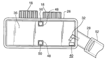
- FIG. 1 is an overall front view of an intake gas cooling device for a supercharged internal combustion engine according to a first embodiment of the present invention (hereinafter also simply referred to as “intake gas cooling device”). It is sectional drawing seen along the front view direction of the low temperature side tank and its vicinity among the intake gas cooling devices which concern on 1st Example of this invention. It is a top view of the low temperature side tank and its vicinity among the intake gas cooling devices which concern on 1st Example of this invention. It is a side view of the low temperature side tank and its vicinity among the intake gas cooling devices which concern on 1st Example of this invention.
- a baffle plate disposed so as to form a concave shape (convex shape toward the upstream side) toward the downstream side in the intake gas flow direction.
- FIGS. 1 to 11 show various structures that the first embodiment of the present invention and the first embodiment of the present invention can take. A part of the structure of the first embodiment of the present invention can be applied to the second to fourth embodiments of the present invention or the second and third embodiments of the present invention.
- 12 shows a second embodiment of the present invention
- FIGS. 13 and 14 show a third embodiment of the present invention
- FIGS. 15 and 16 show a fourth embodiment of the present invention.
- Components that are the same or correspond to one another throughout all embodiments of the invention are labeled with the same reference numerals throughout all embodiments of the invention.
- an intake gas cooling device 10 for a supercharged internal combustion engine of the present invention includes an intercooler 20 in an intake gas passage of the internal combustion engine.
- the intake gas may be called supercharging.
- arrow F indicates the flow direction of the intake gas.
- the supercharger internal combustion engine may be a spark ignition internal combustion engine or a diesel internal combustion engine.
- the turbocharger may be a turbocharger or a mechanical supercharger other than a turbo (mechanical supercharger).
- the intercooler 20 includes a heat exchanger installed in the intake gas passage, and cools the intake gas that has been compressed by the supercharger and raised in temperature, thereby increasing the charging efficiency of the internal combustion engine.
- the throttle valve is provided on the downstream side of the intercooler 20, that is, between the intercooler 20 and the internal combustion engine, and the surge tank and the intake manifold are provided between the throttle valve and the internal combustion engine.
- the intercooler 20 has a high-temperature side tank 22 into which intake gas flows, an intercooler core (hereinafter simply referred to as “core”) 24 for exchanging heat, and a low-temperature side tank 26 from which intake gas flows out.
- the high temperature side tank 22, the core 24, and the low temperature side tank 26 are provided in the order of the high temperature side tank 22, the core 24, and the low temperature side tank 26 in the intake gas flow direction.
- the core 24 may be a downflow type core in which the intake gas flows downward, or may be a crossflow type core in which the intake gas flows in the left-right direction.
- the high temperature side tank 22 is provided above the core 24, and the low temperature side tank 26 is provided below the core 24.
- the high temperature side tank 22 and the low temperature side tank 26 are provided on the left and right sides of the core 24.
- Conventionally known structures are employed for the structure of the high temperature side tank 22 and the core 24, and detailed descriptions thereof are omitted because they are known.
- the high temperature side tank 22 is connected to an inlet pipe 14 that constitutes a part of the intake passage of the internal combustion engine and serves as an intake gas inlet.
- an outlet pipe 28 that constitutes a part of the intake passage of the internal combustion engine and is an outlet of the intake gas.
- the inlet pipe 14 and the outlet pipe 28 may be formed separately from the intercooler 20 and connected to the intercooler 20, or may be formed integrally with the intercooler 20.
- the outlet pipe 28 extends obliquely upward from the side wall of the low temperature side tank 26 toward the throttle valve. In that case, even if the condensed water in the low temperature side tank 26 overflows into the outlet pipe 28, it returns to the low temperature side tank 26 by its own weight.
- the outlet pipe 28 is fitted with a hose 52 (FIGS. 5 to 7) or a pipe constituting an intake passage of the internal combustion engine, and the outlet pipe 28 is fitted into the hose 52 or the pipe.
- the high temperature side tank 22 is supported by the vehicle body via the bracket 16, and the low temperature side tank 26 is supported by the vehicle body via the rib 18.
- a reservoir 30 for temporarily storing condensed water 12 is provided at the lower part of the low temperature side tank 26.
- a water suction pipe 32 extending from the bottom of the reservoir 30 to a position opening in the outlet pipe 28 is provided. The opening position of the water suction pipe 32 into the outlet pipe 28 is located upstream of the throttle valve in the intake gas flow direction.
- the outlet pipe 28 is located downstream of the low temperature side tank 26 in the intake gas flow direction.
- the intake gas passage cross-sectional area in the outlet pipe 28 is smaller than the intake gas passage cross-sectional area in the low-temperature side tank 26, and the intake gas flow rate in the outlet pipe 28 is larger than the intake gas flow rate in the low-temperature side tank 26. . Since the intake gas in the low temperature side tank 26 increases the flow velocity in the outlet pipe 28, a part of the static pressure in the low temperature side tank 26 is changed to dynamic pressure in the outlet pipe 28, and the static pressure in the outlet pipe 28 is It falls below the static pressure in the low temperature side tank 26.
- the static pressure of the intake gas in the outlet pipe 28 is smaller than the static pressure of the intake gas in the low temperature side tank 26 due to the venturi effect due to the static pressure drop due to this flow rate difference and the pressure loss of the intake gas. Due to this pressure difference, the condensed water 12 (FIG. 2) accumulated in the reservoir 30 is sucked into the outlet pipe 28 from the bottom of the reservoir 30 through the water sucking pipe 32. Since the opening position of the water suction pipe 32 into the outlet pipe 28 is located upstream of the throttle valve in the intake gas flow direction, the suction of the condensed water 12 by the water suction pipe 32 uses the intake negative pressure downstream of the throttle. Did not suck out.
- the opening of the water suction pipe 32 toward the outlet pipe 28 may be located inside the outlet pipe 28, or as shown in FIG. It may be located on the inner wall surface.
- the water suction pipe 32 is opened toward the downstream side of the intake gas flow direction from the direction orthogonal to the intake gas flow direction or the direction orthogonal to the intake gas flow direction so as not to receive the dynamic pressure of the intake gas flow. Is open.
- the water suction pipe 32 protrudes from the low temperature side tank 26 into the outlet pipe 28 or ends at the inner wall surface of the outlet pipe 28 (FIG. 14). As shown in FIG.
- the bottom wall 34 of the reservoir 30 is lowered toward the reservoir 30 side end of the water suction pipe 32, and the reservoir 30 side end of the water suction pipe 32 of the bottom wall 34 of the reservoir 30.
- the lower part 34 a of the bottom wall 34 of the reservoir 30 is formed in the vicinity of.
- the end portion of the water suction pipe 32 on the reservoir 30 side is preferably cut obliquely with respect to the bottom wall 34 of the reservoir 30 so as not to be blocked by being in close contact with the bottom wall 34 of the reservoir 30. .
- the condensed water 12 temporarily accumulated in the reservoir 30 is sucked into the outlet pipe 28 by the pressure difference between the both ends of the water sucking pipe 32 even when the engine is idling. Of water, and therefore the height of the reservoir 30 is determined.
- the inner diameter of the water suction pipe 32 is preferably constant over the entire length of the water suction pipe 32 from the viewpoint of manufacturability and moldability. Further, in order to prevent the condensed water 12 temporarily accumulated in the reservoir 30 from being sucked into the outlet pipe 28 in large quantities at a stroke when the engine is started, the malfunction of the internal combustion engine does not occur.
- the inner diameter of the water suction pipe 32 that is constant over the entire length is set to a certain value (for example, 3 mm, preferably 2 mm, but not limited to 3 mm and 2 mm).
- the low temperature side tank 26 and the water suction pipe 32 are preferably made of, for example, a light alloy, such as an aluminum alloy, or a plastic because of its light weight and formability.
- a light alloy such as an aluminum alloy
- a plastic because of its light weight and formability.
- the low temperature side tank 26 is divided into an upper chamber 38 through which intake gas flows and a lower chamber constituting the reservoir 30 by the partition plate 36 (the same as the reservoir 30, the lower chamber code is also 30. And).
- the middle partition plate 36 is provided with a water drop opening 40 through which the condensed water 12 on the middle partition plate 36 is dropped into the reservoir 30 at the lowermost portion of the outlet pipe 28 and the middle partition plate 36.
- the opening 40 may be a hole provided in the partition plate 36 or a notch provided in the partition plate 36.
- the vicinity of the opening of the partition plate 36 may be inclined obliquely downward toward the opening 40.
- the water suction pipe 32 When the water suction pipe 32 is arranged in the low temperature side tank 26, the water suction pipe 32 extends from the reservoir 30 to the upper chamber 38 through the partition plate 36.
- the part through the partition plate 36 of the water suction pipe 32 may be the water drop opening 40 part, or may be a part other than the water drop opening 40.
- the partition plate 36 has an upstream side portion 36 a and a downstream side portion 36 b in the intake gas flow direction in the upper chamber 38.
- the intermediate partition plate 36 is formed in a shape that descends from the upstream side portion 36 a toward the downstream side portion 36 b, and guides the intake gas flow F to the outlet pipe 28.
- a water drop opening 40 is provided in the downstream side portion 36 b of the middle partition plate 36. It is desirable that the vicinity of the water drop opening 40 in the middle partition plate 36 is inclined so as to descend toward the water drop opening 40.
- the upstream side portion 36 a of the partition plate 36 has condensed water 12 when the condensed water 12 accumulated in the reservoir 30 on the lower surface side of the upstream side portion 36 a is frozen while the water dropping opening 40 is closed.
- the space part 42 for absorbing the volume expansion part at the time of freezing is formed.
- the space portion 42 is a space between the lower surface of the upstream side portion 36 a of the partition plate 36 and the upper surface of the condensed water 12 in a state where the condensed water 12 closes the water dropping opening 40.
- a baffle plate 44 is provided on the upper surface of the partition plate 36.
- the baffle plate 44 is disposed so as to block the flow of the condensed water 12 from the low temperature side tank 26 to the outlet pipe 28 when the condensed water 12 overflows from the reservoir 30 onto the partition plate 36.
- each baffle plate 44 has openings 46 through which water on the partition plate 36 can pass so that the flow of the condensed water 12 from the low temperature side tank 26 to the outlet pipe 28 is not completely blocked. 8 to 11) are provided.
- the opening 46 may be a slit (FIG. 8 to FIG. 10) opened over the entire height of the baffle plate 44, or a hole (FIG.
- Each baffle plate 44 extends between the opposing side surfaces of the low temperature side tank 26 except for the opening 46 part. Further, as shown in FIG. 7, when condensed water overflows on the partition plate 36 and a liquid pool is generated up to the upper end position of the baffle plate 44, the liquid pool amount between the baffle plates 44, the liquid downstream from the baffle plate 44 on the most downstream side.
- Each of the baffle plates is set so that the amount of the accumulated liquid and the amount of the accumulated liquid upstream of the uppermost baffle plate 44 are not more than the amount causing the malfunction of the internal combustion engine even if it is taken away by the intake gas flow at once.
- the number of 44, the interval, the height (the height from the partition plate 36 to the upper end of the baffle plate 44), and the arrangement are set.
- the pressure loss when the intake gas flows in the upper chamber 38 is reduced below the pressure loss when the intake gas flows in the outlet pipe 28.
- the openings 46 provided in all the baffle plates 44 are in the same straight line (for example, through the openings 46 provided in any one of the baffle plates 44) in the intake gas flow direction of the low temperature side tank 26.
- the opening 46 provided in the at least one baffle plate 44 is deviated from the same straight line so as not to be positioned on a straight line parallel to the opposing side surface extending in the direction along the direction.
- the baffle plate 44 may be provided to be inclined obliquely upstream from the opening 46 part, or may be provided to be inclined obliquely downstream from the opening 46 part as shown in FIG. Good.
- the low temperature side tank 26 is composed of a container having an open top and has a bottom wall and a side wall.
- a plate 48 that extends in the intake gas flow direction and faces in a direction orthogonal to the intake gas flow direction has a plate 48 that protrudes toward the partition plate 36 at the center of the intake gas flow direction.
- the plate 48 may be connected to the partition plate 36 by bolts and nuts 50.
- the partition plate 36 prevents the side wall of the low temperature side tank 26 from expanding due to supercharging pressure.
- the middle partition plate 36 and the baffle plate 44 are preferably made of, for example, an aluminum alloy or a plastic from the viewpoint of lightness and formability.
- the configurations of the partition plate 36 and the baffle plate 44 described above can also be applied to the second and third embodiments of the present invention.
- the first embodiment of the present invention further has the following configuration.
- the water suction pipe 32 is located in the low temperature side tank 26 and the outlet pipe 28.
- the water suction pipe 32 extends from the reservoir 30 through the intermediate partition plate 36 into the upper chamber 38, bends in the upper chamber 38, protrudes from the upper chamber 38 into the outlet pipe 28, and opens into the outlet pipe 28. is doing.
- the water suction pipe 32 may be supported by the partition plate 36.
- the water suction pipe 32 opens in the outlet pipe 28 toward the downstream side in the intake gas flow direction.
- the condensed water accumulated in the low temperature side tank 26 when the intercooler 20 is frozen during cold running and melted when the internal combustion engine is stopped is sucked into the internal combustion engine in large quantities at once by the flow of intake air when the internal combustion engine is started. There was a risk of malfunction of the internal combustion engine such as liquid compression or rough idle.
- the condensed water may include condensed water that is frozen in the intercooler 20 and melts during operation of the internal combustion engine and accumulates in the low temperature side tank 26 and is sucked into the internal combustion engine in large quantities.
- the condensed water 12 is temporarily discharged from the space in the upper chamber 38 through which the intake gas flows to the reservoir 30, so that the condensed water 12 can be sucked into the internal combustion engine in large quantities at once. Suppressed or prevented. As a result, malfunctions of the internal combustion engine such as liquid compression and rough idle are suppressed or prevented.
- the condensed water 12 temporarily stored in the reservoir 30 is separated from the low temperature side tank 26 site and the outlet. Due to the pressure difference between the low temperature side tank 26 and the outlet pipe 28 caused by the flow velocity difference from the pipe 28 and the pressure loss, the water is sucked into the outlet pipe 28 through the water suction pipe 32. Even during idle rotation, the condensed water accumulated in the reservoir 30 can be sucked into the outlet pipe 28.
- the amount of suction through the water suction pipe 32 is limited by the pressure difference at both ends of the water suction pipe 32, the difference in height position, the inner diameter of the pipe, and the like. Therefore, malfunctions of the internal combustion engine such as liquid compression and rough idling are suppressed.
- the condensed water in the reservoir 30 is not taken away into the outlet pipe 28 in large quantities by the flow of the intake gas flowing through the upper chamber 38.
- the condensed water 12 is dropped from the upper chamber 38 through which the intake gas flows into the reservoir 30 through the water dropping opening 40, a large amount of the condensed water 12 is suppressed from being accumulated on the partition plate 36. As a result, it is possible to prevent a large amount of the condensed water 12 on the partition plate 36 from being sucked into the internal combustion engine at once.
- the middle partition plate 36 is formed in a shape that descends from the upstream side portion 36 a to the downstream side portion 36 b of the middle partition plate 36, and a water drop opening 40 is provided in the downstream side portion 36 b of the middle partition plate 36. Therefore, the condensed water 12 flowing on the partition plate 36 can be guided to the water drop opening 40 and can be effectively dropped to the reservoir 30 through the water drop opening 40.
- the upstream side portion 36a of the partition plate 36 forms a space portion 42 for absorbing the volume expansion when the condensed water 12 accumulated in the reservoir 30 is frozen while the water level rises and the water drop opening 40 is closed. Therefore, the low temperature side tank 26 is prevented from being damaged by the volume expansion due to the freezing of the condensed water 12.
- the partition plate 36 extends between the opposing side surfaces of the low temperature side tank 26 and is connected to the opposing side surfaces of the low temperature side tank 26, when a supercharging pressure higher than atmospheric pressure is applied to the opposing side surface of the low temperature side tank 26. It can suppress or prevent that the opposing side surface of the low temperature side tank 26 deform
- the baffle plate 44 is disposed so as to block the flow of the condensed water 12 from the low temperature side tank 26 to the outlet pipe 28 when the condensed water 12 overflows on the partition plate 36, the baffle plate 44 is disposed in the condensed water 12.
- the discharge speed from the low temperature side tank 26 to the outlet pipe 28 can be slowed, and malfunction of the internal combustion engine can be prevented or suppressed.
- the first embodiment of the present invention further has the following actions and effects. Since the water suction pipe 32 is disposed in the low temperature side tank 26 and the outlet pipe 28, the outer shape of the low temperature side tank 26 and the outlet pipe 28 is not provided with the water suction pipe 32 even if the water suction pipe 32 is provided. It doesn't get bigger. As a result, the intake gas cooling device 10 is compact and has excellent mountability on a vehicle.
- FIG. In the second embodiment of the present invention, in addition to the configuration, operation, and effect that can be applied to the second embodiment of the present invention, the configuration, operation, and effect according to the first embodiment of the present invention, FIG. It has the following composition, operation, and effect.
- the water suction pipe 32 once goes out of the low temperature side tank 26 to the outside of the low temperature side tank 26 and connects the inside of the reservoir 30 and the inside of the outlet pipe 28.
- the water suction pipe 32 includes a connecting pipe 32 a that passes through the wall of the reservoir 30, a connecting pipe 32 b that passes through the wall of the outlet pipe 28, and a hose 32 c that connects the connecting pipes 32 a and 32 b outside the reservoir 30. You may be comprised from.
- the third embodiment of the present invention includes, in addition to the configuration, operation, and effect that can be applied to the third embodiment of the present invention, among the configuration, operation, and effect according to the first embodiment of the present invention.
- FIG. 14 shows the following configuration, operation, and effects.
- the outlet pipe 28 In the outlet pipe 28, the cross-sectional area reduced portion 28a whose cross-sectional area is gradually reduced in the intake gas flow direction, the throat portion 28b whose cross-sectional area is reduced most, and the cross-sectional area whose cross-sectional area is gradually enlarged in the intake gas flow direction
- the enlarged portion 28c is provided in order in the intake gas flow direction. Therefore, in the third embodiment, the outlet pipe 28 is a Venturi tube.
- the open end of the water suction pipe 32 into the outlet pipe 28 is located at the center of the throat 28b or at the outer periphery.
- the water suction pipe 32 extends from the reservoir 30 to the upper chamber 38 in the low temperature side tank 26 and protrudes from the upper chamber 38 in the low temperature side tank 26 into the outlet pipe 28.
- the open end of the water suction pipe 32 into the outlet pipe 28 is at the center of the cross section of the outlet pipe 28 at the throat 28b.
- the water suction pipe 32 once goes out of the low temperature side tank 26 from the low temperature side tank 26 and connects the reservoir 30 and the outlet pipe 28.
- the water suction pipe 32 is connected to a hole 32 d provided in the wall of the outlet pipe 28.
- the open end of the water suction pipe 32 into the outlet pipe 28 is on the inner peripheral surface of the outlet pipe 28 in the throat 28b.
- the outlet pipe 28 is made of a Venturi tube, the pressure loss can be reduced to obtain a low pressure at the open end of the water suction pipe 32 into the outlet pipe 28. Further, since the opening end of the water suction pipe 32 into the outlet pipe 28 is provided in the throat portion 28b, the venturi effect of the outlet pipe 28 is enhanced, and the condensed water suction effect by the water suction pipe 32 is enhanced.
- FIG. 16 shows the following configuration, operation, and effects.
- the core 24 is formed of a cross flow type core in which the intake gas flows in the left-right direction in FIG. In that case, it extends in the vertical direction of the low temperature side tank 26, and the outlet pipe 28 is provided at a portion other than the lower end portion of the low temperature side tank 26, and thus at the intermediate portion or the upper end portion of the low temperature side tank 26.
- the outlet pipe 28 extends toward the back side in a direction orthogonal to the paper surface of FIG. 15, and extends in a direction orthogonal to the left-right direction of FIG.
- a water suction pipe 32 extends from the bottom of the reservoir 30 to a position where it opens into the outlet pipe 28.
- the water suction pipe 32 may be in the low temperature side tank 26 and the outlet pipe 28, or once out of the low temperature side tank 26 from the wall of the low temperature side tank 26 and passing through the wall of the outlet pipe 28. You may open in.
- a partition plate 36 may be provided in the low temperature side tank 26, or may not be provided as shown in FIG.
- the water sucking pipe 32 extends from the bottom of the reservoir 30 to a position where it opens into the outlet pipe 28, the condensate water 12 can be sucked into the cross flow type intercooler 20 with the sucking out being suppressed at once. It is.
- the partition plate 36 and the baffle plate 44 are not provided.
- the partition plate 36 and the baffle plate 44 may be provided. In that case, the configuration, operation, and effects of the partition plate 36 and the baffle plate 44 can be applied to the second and third embodiments in the first embodiment. Actions and effects can be applied mutatis mutandis.
Landscapes
- Engineering & Computer Science (AREA)
- Physics & Mathematics (AREA)
- Thermal Sciences (AREA)
- Mechanical Engineering (AREA)
- General Engineering & Computer Science (AREA)
- Chemical & Material Sciences (AREA)
- Combustion & Propulsion (AREA)
- Supercharger (AREA)
Abstract
L'invention concerne un dispositif de refroidissement de gaz d'admission (10) pour un moteur à combustion interne suralimenté, caractérisé en ce qu'un réservoir (30) qui maintient temporairement de l'eau de condensation est ménagé dans la partie inférieure d'une cuve côté basse température (26), et un tuyau d'extraction d'eau (32) s'étend du fond du réservoir (30) dans l'intérieur d'un tuyau de sortie (28). Le réservoir (30) est séparé d'une chambre supérieure (38) par une plaque de séparation interne (36), et une ouverture d'écoulement d'eau (40) est ménagée dans la plaque de séparation interne (36). Des plaques déflectrices (44) sont ménagées sur la partie supérieure de la plaque de séparation interne (36). L'eau de condensation est évacuée dans le réservoir (30) temporairement, et est extraite à travers le tuyau d'extraction d'eau (32), ce qui empêche l'eau de condensation d'être emportée en une seule fois. Le réservoir (30) est séparé de la chambre supérieure (38) par la plaque de séparation interne (36), de sorte que l'eau de condensation n'est pas emportée en une seule fois. Même si l'eau de condensation s'accumule sur la plaque de séparation interne (36), les plaques déflectrices (44) empêchent l'eau de condensation d'être emportée en une seule fois. Ainsi, il est possible d'empêcher que la condensation d'eau dans l'air suralimenté s'écoule dans le moteur à combustion interne en une seule fois et provoque un mauvais fonctionnement du moteur.
Priority Applications (2)
| Application Number | Priority Date | Filing Date | Title |
|---|---|---|---|
| EP14848351.4A EP3051096B1 (fr) | 2013-09-24 | 2014-09-24 | Dispositif de refroidissement de gaz d'admission pour moteur à combustion interne suralimenté |
| ZA2016/02009A ZA201602009B (en) | 2013-09-24 | 2016-03-23 | Intake gas cooling device for supercharging internal combustion engine |
Applications Claiming Priority (2)
| Application Number | Priority Date | Filing Date | Title |
|---|---|---|---|
| JP2013-196768 | 2013-09-24 | ||
| JP2013196768A JP6185349B2 (ja) | 2013-09-24 | 2013-09-24 | 過給式内燃機関のインテークガス冷却装置 |
Publications (1)
| Publication Number | Publication Date |
|---|---|
| WO2015046182A1 true WO2015046182A1 (fr) | 2015-04-02 |
Family
ID=52743318
Family Applications (1)
| Application Number | Title | Priority Date | Filing Date |
|---|---|---|---|
| PCT/JP2014/075155 WO2015046182A1 (fr) | 2013-09-24 | 2014-09-24 | Dispositif de refroidissement de gaz d'admission pour moteur à combustion interne suralimenté |
Country Status (5)
| Country | Link |
|---|---|
| EP (1) | EP3051096B1 (fr) |
| JP (1) | JP6185349B2 (fr) |
| TR (1) | TR201810067T4 (fr) |
| WO (1) | WO2015046182A1 (fr) |
| ZA (1) | ZA201602009B (fr) |
Cited By (4)
| Publication number | Priority date | Publication date | Assignee | Title |
|---|---|---|---|---|
| US20150184581A1 (en) * | 2013-12-26 | 2015-07-02 | Mazda Motor Corporation | Intake system for engine |
| EP3095995A1 (fr) * | 2015-05-20 | 2016-11-23 | Mahle International GmbH | Refroidisseur d'air de suralimentation |
| US10288012B2 (en) | 2016-01-28 | 2019-05-14 | Ford Global Technologies, Llc | Arrangement for introducing water into the intake manifold of an internal combustion engine and control device |
| CN113464269A (zh) * | 2021-08-20 | 2021-10-01 | 浙江吉利控股集团有限公司 | 一种具有冷凝水自排出功能的中冷器 |
Families Citing this family (7)
| Publication number | Priority date | Publication date | Assignee | Title |
|---|---|---|---|---|
| JP6036767B2 (ja) * | 2014-08-27 | 2016-11-30 | トヨタ自動車株式会社 | 過給式内燃機関のインタークーラ装置 |
| US9719470B2 (en) * | 2015-05-08 | 2017-08-01 | Ford Global Technologies, Llc | Inlet manifold with water-transporting straws |
| DE102016214886A1 (de) * | 2016-08-10 | 2018-02-15 | Mahle International Gmbh | Ladeluftkühler, insbesondere für ein Kraftfahrzeug |
| JP6662241B2 (ja) * | 2016-08-24 | 2020-03-11 | 株式会社デンソー | 冷却装置 |
| JP6860313B2 (ja) * | 2016-09-12 | 2021-04-14 | 日産自動車株式会社 | エンジンの制御方法、及び、エンジン |
| JP6919282B2 (ja) * | 2017-04-04 | 2021-08-18 | いすゞ自動車株式会社 | 熱交換器のパイプ取付構造 |
| JP7287292B2 (ja) * | 2020-01-20 | 2023-06-06 | マツダ株式会社 | エンジンの吸気装置 |
Citations (8)
| Publication number | Priority date | Publication date | Assignee | Title |
|---|---|---|---|---|
| JPS4918843B1 (fr) * | 1969-06-07 | 1974-05-13 | ||
| JPS57152428U (fr) * | 1981-03-23 | 1982-09-24 | ||
| JP2005226476A (ja) * | 2004-02-10 | 2005-08-25 | Toyota Motor Corp | 吸気通路内蓄積オイルの排出構造 |
| JP2012102667A (ja) | 2010-11-10 | 2012-05-31 | Denso Corp | 吸気冷却装置 |
| JP2012117455A (ja) | 2010-12-01 | 2012-06-21 | Hino Motors Ltd | 熱交換器の凝縮水貯留排出機構 |
| JP2012140868A (ja) * | 2010-12-28 | 2012-07-26 | Mitsubishi Motors Corp | エンジンの制御装置 |
| JP2013164006A (ja) * | 2012-02-10 | 2013-08-22 | Denso Corp | 内燃機関用吸気装置 |
| JP2014169632A (ja) * | 2013-03-01 | 2014-09-18 | Mitsubishi Motors Corp | 内燃機関のインタークーラ凝縮水排出装置 |
Family Cites Families (3)
| Publication number | Priority date | Publication date | Assignee | Title |
|---|---|---|---|---|
| DE3601391A1 (de) * | 1986-01-18 | 1987-02-26 | Daimler Benz Ag | Vorrichtung zum absaugen von in den luftsammelkasten eines ladeluftkuehlers abtropfendes kondensatoel |
| FR2908505B1 (fr) * | 2006-11-14 | 2009-02-13 | Renault Sas | Echangeur thermique comportant des moyens de purge automatique. |
| FR2922962B1 (fr) * | 2007-10-24 | 2014-04-18 | Valeo Systemes Thermiques | Dispositif de recuperation et d'evacuation de produits de condensation d'un flux d'air d'admission |
-
2013
- 2013-09-24 JP JP2013196768A patent/JP6185349B2/ja active Active
-
2014
- 2014-09-24 WO PCT/JP2014/075155 patent/WO2015046182A1/fr active Application Filing
- 2014-09-24 EP EP14848351.4A patent/EP3051096B1/fr active Active
- 2014-09-24 TR TR2018/10067T patent/TR201810067T4/tr unknown
-
2016
- 2016-03-23 ZA ZA2016/02009A patent/ZA201602009B/en unknown
Patent Citations (8)
| Publication number | Priority date | Publication date | Assignee | Title |
|---|---|---|---|---|
| JPS4918843B1 (fr) * | 1969-06-07 | 1974-05-13 | ||
| JPS57152428U (fr) * | 1981-03-23 | 1982-09-24 | ||
| JP2005226476A (ja) * | 2004-02-10 | 2005-08-25 | Toyota Motor Corp | 吸気通路内蓄積オイルの排出構造 |
| JP2012102667A (ja) | 2010-11-10 | 2012-05-31 | Denso Corp | 吸気冷却装置 |
| JP2012117455A (ja) | 2010-12-01 | 2012-06-21 | Hino Motors Ltd | 熱交換器の凝縮水貯留排出機構 |
| JP2012140868A (ja) * | 2010-12-28 | 2012-07-26 | Mitsubishi Motors Corp | エンジンの制御装置 |
| JP2013164006A (ja) * | 2012-02-10 | 2013-08-22 | Denso Corp | 内燃機関用吸気装置 |
| JP2014169632A (ja) * | 2013-03-01 | 2014-09-18 | Mitsubishi Motors Corp | 内燃機関のインタークーラ凝縮水排出装置 |
Cited By (7)
| Publication number | Priority date | Publication date | Assignee | Title |
|---|---|---|---|---|
| US20150184581A1 (en) * | 2013-12-26 | 2015-07-02 | Mazda Motor Corporation | Intake system for engine |
| US9528427B2 (en) * | 2013-12-26 | 2016-12-27 | Mazda Motor Corporation | Intake system for engine |
| EP3095995A1 (fr) * | 2015-05-20 | 2016-11-23 | Mahle International GmbH | Refroidisseur d'air de suralimentation |
| WO2016184917A1 (fr) * | 2015-05-20 | 2016-11-24 | Mahle International Gmbh | Refroidisseur d'air de suralimentation comprenant un collecteur de condensat |
| US10100715B2 (en) | 2015-05-20 | 2018-10-16 | Mahle International Gmbh | Inter cooler |
| US10288012B2 (en) | 2016-01-28 | 2019-05-14 | Ford Global Technologies, Llc | Arrangement for introducing water into the intake manifold of an internal combustion engine and control device |
| CN113464269A (zh) * | 2021-08-20 | 2021-10-01 | 浙江吉利控股集团有限公司 | 一种具有冷凝水自排出功能的中冷器 |
Also Published As
| Publication number | Publication date |
|---|---|
| TR201810067T4 (tr) | 2018-08-27 |
| ZA201602009B (en) | 2017-08-30 |
| JP2015063913A (ja) | 2015-04-09 |
| EP3051096A1 (fr) | 2016-08-03 |
| EP3051096A4 (fr) | 2016-09-14 |
| EP3051096B1 (fr) | 2018-06-27 |
| JP6185349B2 (ja) | 2017-08-23 |
Similar Documents
| Publication | Publication Date | Title |
|---|---|---|
| JP6185349B2 (ja) | 過給式内燃機関のインテークガス冷却装置 | |
| US6460525B1 (en) | Separator and oil trap for closed crankcase ventilator systems | |
| JP3177942U (ja) | 往復動ピストン燃焼機関用の給気冷却器 | |
| CN101960105B (zh) | 内燃机的进气管结构 | |
| JP5478399B2 (ja) | エンジンのブローバイガス還流装置 | |
| CN109469599B (zh) | 一种吸气消音器及压缩机 | |
| JP2009108761A (ja) | インタークーラ | |
| JPH04227442A (ja) | 凝縮器 | |
| CN204060857U (zh) | 发动机缸盖护罩及曲轴箱通风系统 | |
| JP6459498B2 (ja) | エンジンの吸気構造 | |
| JP6036767B2 (ja) | 過給式内燃機関のインタークーラ装置 | |
| JP5505255B2 (ja) | 内燃機関の吸気装置 | |
| KR20080103278A (ko) | 소음기 및 이를 포함하는 냉장고 | |
| JP2007332874A (ja) | ブローバイガスのトラップ装置 | |
| CN109139189A (zh) | 用于国六发动机的闭式曲轴箱强制通风系统油气分离器 | |
| CN104775892A (zh) | 一种发动机水冷式中冷器 | |
| JP5504198B2 (ja) | エンジン | |
| JP5800607B2 (ja) | Egrガス通路構造 | |
| JP2010138776A (ja) | 燃料供給装置 | |
| JP2008057501A (ja) | エンジンのオイルセパレータ | |
| CN204202262U (zh) | 三级分离式高效卧式分油装置 | |
| CN112556254A (zh) | 油分离器、空调系统 | |
| DK173569B1 (da) | Trykladet forbrændingsmotor af dieseltypen med ladeluftvandudskiller | |
| CN218787145U (zh) | 增压器壳体、曲轴箱通风系统及车辆 | |
| JP2012112297A (ja) | 内燃機関の吸気装置 |
Legal Events
| Date | Code | Title | Description |
|---|---|---|---|
| 121 | Ep: the epo has been informed by wipo that ep was designated in this application |
Ref document number: 14848351 Country of ref document: EP Kind code of ref document: A1 |
|
| REEP | Request for entry into the european phase |
Ref document number: 2014848351 Country of ref document: EP |
|
| WWE | Wipo information: entry into national phase |
Ref document number: 2014848351 Country of ref document: EP |
|
| NENP | Non-entry into the national phase |
Ref country code: DE |