WO2015046182A1 - Intake gas cooling device for supercharged internal combustion engine - Google Patents
Intake gas cooling device for supercharged internal combustion engine Download PDFInfo
- Publication number
- WO2015046182A1 WO2015046182A1 PCT/JP2014/075155 JP2014075155W WO2015046182A1 WO 2015046182 A1 WO2015046182 A1 WO 2015046182A1 JP 2014075155 W JP2014075155 W JP 2014075155W WO 2015046182 A1 WO2015046182 A1 WO 2015046182A1
- Authority
- WO
- WIPO (PCT)
- Prior art keywords
- intake gas
- outlet pipe
- reservoir
- internal combustion
- combustion engine
- Prior art date
Links
Images


Classifications
-
- F—MECHANICAL ENGINEERING; LIGHTING; HEATING; WEAPONS; BLASTING
- F02—COMBUSTION ENGINES; HOT-GAS OR COMBUSTION-PRODUCT ENGINE PLANTS
- F02B—INTERNAL-COMBUSTION PISTON ENGINES; COMBUSTION ENGINES IN GENERAL
- F02B29/00—Engines characterised by provision for charging or scavenging not provided for in groups F02B25/00, F02B27/00 or F02B33/00 - F02B39/00; Details thereof
- F02B29/04—Cooling of air intake supply
- F02B29/045—Constructional details of the heat exchangers, e.g. pipes, plates, ribs, insulation, materials, or manufacturing and assembly
- F02B29/0468—Water separation or drainage means
-
- F—MECHANICAL ENGINEERING; LIGHTING; HEATING; WEAPONS; BLASTING
- F28—HEAT EXCHANGE IN GENERAL
- F28F—DETAILS OF HEAT-EXCHANGE AND HEAT-TRANSFER APPARATUS, OF GENERAL APPLICATION
- F28F17/00—Removing ice or water from heat-exchange apparatus
- F28F17/005—Means for draining condensates from heat exchangers, e.g. from evaporators
-
- F—MECHANICAL ENGINEERING; LIGHTING; HEATING; WEAPONS; BLASTING
- F28—HEAT EXCHANGE IN GENERAL
- F28D—HEAT-EXCHANGE APPARATUS, NOT PROVIDED FOR IN ANOTHER SUBCLASS, IN WHICH THE HEAT-EXCHANGE MEDIA DO NOT COME INTO DIRECT CONTACT
- F28D21/00—Heat-exchange apparatus not covered by any of the groups F28D1/00 - F28D20/00
- F28D2021/0019—Other heat exchangers for particular applications; Heat exchange systems not otherwise provided for
- F28D2021/008—Other heat exchangers for particular applications; Heat exchange systems not otherwise provided for for vehicles
- F28D2021/0082—Charged air coolers
-
- F—MECHANICAL ENGINEERING; LIGHTING; HEATING; WEAPONS; BLASTING
- F28—HEAT EXCHANGE IN GENERAL
- F28F—DETAILS OF HEAT-EXCHANGE AND HEAT-TRANSFER APPARATUS, OF GENERAL APPLICATION
- F28F2265/00—Safety or protection arrangements; Arrangements for preventing malfunction
- F28F2265/06—Safety or protection arrangements; Arrangements for preventing malfunction by using means for draining heat exchange media from heat exchangers
-
- F—MECHANICAL ENGINEERING; LIGHTING; HEATING; WEAPONS; BLASTING
- F28—HEAT EXCHANGE IN GENERAL
- F28F—DETAILS OF HEAT-EXCHANGE AND HEAT-TRANSFER APPARATUS, OF GENERAL APPLICATION
- F28F2265/00—Safety or protection arrangements; Arrangements for preventing malfunction
- F28F2265/22—Safety or protection arrangements; Arrangements for preventing malfunction for draining
-
- Y—GENERAL TAGGING OF NEW TECHNOLOGICAL DEVELOPMENTS; GENERAL TAGGING OF CROSS-SECTIONAL TECHNOLOGIES SPANNING OVER SEVERAL SECTIONS OF THE IPC; TECHNICAL SUBJECTS COVERED BY FORMER USPC CROSS-REFERENCE ART COLLECTIONS [XRACs] AND DIGESTS
- Y02—TECHNOLOGIES OR APPLICATIONS FOR MITIGATION OR ADAPTATION AGAINST CLIMATE CHANGE
- Y02T—CLIMATE CHANGE MITIGATION TECHNOLOGIES RELATED TO TRANSPORTATION
- Y02T10/00—Road transport of goods or passengers
- Y02T10/10—Internal combustion engine [ICE] based vehicles
- Y02T10/12—Improving ICE efficiencies
Definitions
- the present invention relates to an intake gas cooling device for a supercharged internal combustion engine, and more particularly to a condensed water discharge structure of the intake gas cooling device.
- Patent Document 1 discloses a structure in which a condensate accumulation portion generated in an intake gas is set in an intercooler tank and the condensed water is temporarily accumulated therein as an intake gas cooling device for a conventional supercharged internal combustion engine. is doing. Moreover, the drain set to the lower end of the pool part of condensed water is disclosed.
- Patent Document 2 discloses a vacuum pipe using an intake manifold negative pressure as means for sucking condensed water and oil in an intercooler tank into an internal combustion engine.
- the conventional intake gas cooling device for a supercharged internal combustion engine has the following problems.
- the reservoir Since the reservoir is not set as a separate chamber from the intake gas flow, the condensed water accumulated in the reservoir is taken away at a stretch by the flow rate of the intake gas flowing in the intercooler, causing malfunction of the internal combustion engine (malfunction). There is a risk of causing.
- icing formed in the core of the intercooler during cold running melts and accumulates in the intercooler when the internal combustion engine is stopped, and is taken away by the flow of intake gas when the engine is started and sucked into the internal combustion engine for liquid compression and roughing.
- malfunction of the internal combustion engine such as idling or abnormal noise. In the case of drain, maintenance work is required periodically.
- the suction through the vacuum piping using the intake manifold negative pressure may not be able to be performed because the negative pressure is insufficient in the low rotation range in a small displacement vehicle.
- vacuum piping from the intercooler tank to the intake manifold is required.
- An object of the present invention is to provide an intake gas cooling device for a supercharged internal combustion engine that suppresses or prevents a large amount of condensed water in an intercooler from being sucked into the internal combustion engine at once.
- the intake gas cooling device for a supercharged internal combustion engine of the present invention that achieves the above object can have the following first to eleventh configurations.
- the first to eleventh configurations can be applied to any of the first to fourth embodiments of the present invention described later.
- the first embodiment of the present invention can have the following twelfth to thirteenth configurations
- the second embodiment of the present invention can have the following fourteenth configuration
- the third embodiment of the present invention has the following configurations:
- the fifteenth to seventeenth configurations can be adopted, and the fourth embodiment of the present invention can adopt the following eighteenth configuration.
- the intake gas cooling device for a supercharged internal combustion engine includes an intercooler in the intake gas passage.
- the intercooler has a low temperature side tank.
- An outlet pipe is connected to the low temperature side tank.
- a reservoir for temporarily storing condensed water is provided at the lower part of the low temperature side tank.
- a water suction pipe is provided that extends from the bottom of the reservoir to a position that opens into the outlet pipe.
- a part or all of the water suction pipe may be a hose.
- the opening of the water suction pipe into the outlet pipe is located upstream of the throttle valve in the intake gas flow direction.
- the opening of the water suction pipe into the outlet pipe is a direction orthogonal to the intake gas flow direction or a direction orthogonal to the intake gas flow direction. It is directed in a direction toward the downstream side of the intake gas flow direction.
- the difference in height position between the opening portion of the water suction pipe into the outlet pipe and the end portion on the reservoir side is: It is set so that the condensed water accumulated in the reservoir can be sucked out into the outlet pipe by the pressure difference between both ends of the water sucking pipe even during idle rotation of the supercharged internal combustion engine.
- the inner diameter of the water suction pipe that is constant over the entire length of the water is set so that a large amount of condensed water stored in the reservoir is not sucked into the outlet pipe at once when the engine is started.
- the bottom wall of the reservoir descends toward the end of the water suction pipe on the reservoir side.
- the vicinity of the reservoir side end of the water suction pipe forms the lowest part of the bottom wall of the reservoir.
- the low temperature side tank is divided into an upper chamber through which an intake gas flows and a lower chamber configuring the reservoir by the partition plate.
- the middle partition plate is provided with a water drop opening for dropping condensed water on the middle partition plate into the reservoir at the bottom of the middle partition plate including the outlet pipe.
- the low temperature side tank is a container having a bottom wall and a side wall that opens upward.
- the middle partition plate extends across an opposing side wall that faces the direction orthogonal to the intake gas flow direction and extends in the intake gas flow direction, and the opposed side wall is connected to the middle partition plate.
- the partition plate in the sixth or seventh configuration, has an upstream portion and a downstream portion in the intake gas flow direction, and the partition plate is downstream from the upstream portion. It is formed in a shape that descends toward the side.
- the water drop opening is provided on the downstream side of the partition plate.
- the upstream side portion of the partition plate forms a space portion on the lower surface side of the upstream side portion for absorbing the volume expansion when the condensed water accumulated in the reservoir is frozen while the water drop opening is closed. .
- a baffle plate is provided on the upper surface of the partition plate.
- the baffle plate is disposed so as to block the flow of the condensed water from the low temperature side tank to the outlet pipe when the condensed water overflows on the partition plate.
- a cross-sectional area larger than the cross-sectional area of the outlet pipe is secured above the baffle plate.
- baffle plates are provided in the ninth configuration.
- Each baffle plate is provided with an opening through which water on the partition plate can pass.
- the openings of at least one baffle plate are offset from the same straight line so that all the baffle plate openings do not lie on the same straight line.
- the baffle plate in the eleventh configuration, is provided to be inclined obliquely upstream or obliquely downstream from the opening portion.
- the water suction pipe extends from the reservoir through the partition plate to the upper chamber and bends in the upper chamber from the upper chamber. It protrudes into the outlet pipe and opens into the outlet pipe.
- the lower end of the water suction pipe is cut obliquely with respect to the bottom wall of the reservoir.
- the water suction pipe once goes out of the low temperature side tank and connects the inside of the reservoir and the inside of the outlet pipe.
- the outlet pipe has a cross-sectional area reduced portion in which the cross-sectional area is gradually reduced in the intake gas flow direction, and the cross-sectional area is the largest.
- a reduced throat portion and a cross-sectional area enlarged portion in which the cross-sectional area is gradually increased in the intake gas flow direction are sequentially provided in the intake gas flow direction.
- the open end of the water suction pipe into the outlet pipe is located at the throat.
- the water suction pipe extends from the reservoir to the upper chamber in the low temperature side tank and protrudes from the low temperature side tank into the outlet pipe in the upper chamber.
- the open end of the water suction pipe into the outlet pipe is located in the center of the cross section of the outlet pipe in the throat.
- the water suction pipe once goes out of the low temperature side tank and connects the inside of the reservoir and the inside of the outlet pipe.
- the water suction pipe is connected to a hole provided in the wall of the outlet pipe, and the opening end of the hole connected to the water suction pipe to the outlet pipe is located on the inner peripheral surface of the outlet pipe in the throat.
- the intercooler in any one of the first to eleventh configurations, is a downflow type core in which the intake gas flows downward, or a cross flow in which the intake gas flows in the left-right direction.
- An outlet pipe is provided at the middle or upper end in the vertical direction of the low temperature side tank. A region located below the outlet pipe in the low temperature side tank constitutes the reservoir, and the water suction pipe extends from the bottom of the reservoir to a position where it opens into the outlet pipe.
- the condensed water is temporarily discharged to the reservoir from the passage through which the intake gas flows, so that a large amount of condensed water in the intercooler is blown at a stroke. Is suppressed or prevented, and malfunctions of the internal combustion engine such as liquid compression and rough idle are suppressed or prevented.
- a water suction pipe that extends from the bottom of the reservoir to a position that opens into the outlet pipe is provided, so that the condensed water temporarily stored in the reservoir has a difference in flow rate and pressure loss between the tank and the outlet pipe. Due to the pressure difference between the tank part and the outlet pipe part caused by the above, the water is sucked into the outlet pipe through the water suction pipe.
- the amount of water drawn through the water suction pipe is limited by the pressure difference at both ends of the water suction pipe, the difference in height position, the pipe diameter, etc., so a large amount of condensed water in the reservoir will not be sucked into the outlet pipe at once. Therefore, malfunctions of the internal combustion engine such as liquid compression and rough idle are suppressed.
- the opening of the water suction pipe into the outlet pipe is located upstream of the throttle valve in the intake gas flow direction. Therefore, it is possible to suppress a problem that suction in a vacuum pipe using intake manifold negative pressure may not be possible due to a lack of negative pressure in a low rotation range in a vehicle with a small displacement.
- the opening of the water suction pipe into the outlet pipe is in the direction orthogonal to the intake gas flow direction or downstream of the intake gas flow direction from the direction orthogonal to the intake gas flow direction. It is aimed in the direction of heading. For this reason, the water suction pipe is not subjected to the dynamic pressure of the intake gas flow or is difficult to receive.
- the difference in height position between both ends of the water suction pipe is set as described in the fourth configuration. Therefore, even during idle rotation of the supercharged internal combustion engine, the condensed water stored in the reservoir can be sucked into the outlet pipe due to the pressure difference between both ends of the water sucking pipe. Moreover, since the inner diameter of the water suction pipe, which is constant over the entire length of the water suction pipe, is set as described in the fourth configuration, a large amount of condensed water stored in the reservoir is discharged at a time when the engine is started. Sucking into the pipe is suppressed.
- the bottom wall of the reservoir descends toward the reservoir-side end of the water suction pipe. Therefore, the condensed water in the reservoir collects toward the lower end of the water suction pipe.
- the reservoir is partitioned from the upper chamber by the partition plate, a large amount of water in the reservoir is rapidly put into the outlet pipe by the flow of the intake gas flowing through the upper chamber. It is never taken away. Since the condensed water is dropped from the upper chamber through which the intake gas flows into the reservoir through the water dropping opening, a large amount of condensed water is suppressed from being accumulated on the partition plate. Therefore, it is suppressed that a large amount of condensed water stays on the partition plate and a large amount of condensed water is sucked into the internal combustion engine at once.
- the intermediate partition plate extends in the opposite side wall extending in the intake gas flow direction while facing the direction orthogonal to the intake gas flow direction, and the opposed side wall is connected to the intermediate partition plate. Has been. Therefore, the partition plate 36 suppresses or prevents the supercharging pressure from being applied and the side wall of the low temperature side tank 26 from expanding.
- the partition plate is formed in a shape descending from the upstream side portion toward the downstream side portion, and a water drop opening is provided in the downstream side portion of the partition plate. . Therefore, the condensed water flowing on the partition plate can be guided to the water drop opening, and can be effectively dropped to the reservoir through the water drop opening. Further, the upstream side portion of the partition plate forms a space portion for absorbing the volume expansion when the condensed water accumulated in the reservoir is frozen in a state where the water drop opening is closed. The tank is prevented from being damaged by the volume expansion due to freezing of condensed water.
- the baffle plate slows the discharge rate of the condensed water from the low temperature side tank to the outlet pipe when the reservoir is full and the condensed water overflows on the partition plate. Therefore, malfunction of the internal combustion engine can be prevented or suppressed. Further, since the upper chamber has a cross-sectional area larger than the cross-sectional area of the outlet pipe above the baffle plate, deterioration of the pressure loss of the intake gas flow when flowing through the upper chamber is suppressed.
- the openings of at least one baffle plate are offset from the same straight line so that the openings of all the baffle plates are not located on the same straight line.
- the discharge speed of the condensed water flowing on the partition plate to the outlet pipe is effectively slowed, and malfunction of the internal combustion engine is effectively prevented or suppressed.
- the baffle plate is provided so as to be inclined obliquely upstream or obliquely downstream from the opening portion.
- the baffle plate is directed obliquely upstream, the condensed water flowing from the upstream side can be effectively guided to the opening.
- the baffle plate is directed obliquely downstream, the condensate discharge rate to the outlet pipe is slow, and the volume of the downstream area can be reduced from the baffle plate at the most downstream stage, which cannot be controlled. it can.
- the intake gas cooling device is as compact as the case where the water suction pipe is not provided, and is excellent in mountability to the vehicle.
- the lower end of the water suction pipe is cut obliquely with respect to the bottom wall of the reservoir. Therefore, it is suppressed that the lower end of the water suction pipe is blocked by the bottom wall of the reservoir.
- the water suction pipe does not reach the lowermost end of the low temperature side tank due to an irregular shape or the like, it is routed outside the low temperature side tank.
- the water suction pipe By constituting the water suction pipe from the pipe (including the case where the pipe is a hose), the inside of the reservoir and the outlet pipe can be easily connected.
- the open end of the water suction pipe into the outlet pipe is located at the center of the cross section at the throat of the outlet pipe.
- This arrangement structure in the throat portion at the opening end of the water suction pipe can be applied when the water suction pipe protrudes from the low temperature side tank into the outlet pipe.
- the opening end of the water suction pipe into the outlet pipe is located on the inner peripheral surface of the throat of the outlet pipe.
- This arrangement structure in the throat portion at the opening end of the water suction pipe can be applied when the water suction pipe once goes out of the low temperature side tank and connects the inside of the reservoir and the inside of the outlet pipe.
- the eighteenth configuration of the present invention it is possible to suck out condensed water with a large amount of sucking suppressed at a stretch even for a downflow type or crossflow type intercooler.
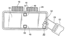
- FIG. 1 is an overall front view of an intake gas cooling device for a supercharged internal combustion engine according to a first embodiment of the present invention (hereinafter also simply referred to as “intake gas cooling device”). It is sectional drawing seen along the front view direction of the low temperature side tank and its vicinity among the intake gas cooling devices which concern on 1st Example of this invention. It is a top view of the low temperature side tank and its vicinity among the intake gas cooling devices which concern on 1st Example of this invention. It is a side view of the low temperature side tank and its vicinity among the intake gas cooling devices which concern on 1st Example of this invention.
- a baffle plate disposed so as to form a concave shape (convex shape toward the upstream side) toward the downstream side in the intake gas flow direction.
- FIGS. 1 to 11 show various structures that the first embodiment of the present invention and the first embodiment of the present invention can take. A part of the structure of the first embodiment of the present invention can be applied to the second to fourth embodiments of the present invention or the second and third embodiments of the present invention.
- 12 shows a second embodiment of the present invention
- FIGS. 13 and 14 show a third embodiment of the present invention
- FIGS. 15 and 16 show a fourth embodiment of the present invention.
- Components that are the same or correspond to one another throughout all embodiments of the invention are labeled with the same reference numerals throughout all embodiments of the invention.
- an intake gas cooling device 10 for a supercharged internal combustion engine of the present invention includes an intercooler 20 in an intake gas passage of the internal combustion engine.
- the intake gas may be called supercharging.
- arrow F indicates the flow direction of the intake gas.
- the supercharger internal combustion engine may be a spark ignition internal combustion engine or a diesel internal combustion engine.
- the turbocharger may be a turbocharger or a mechanical supercharger other than a turbo (mechanical supercharger).
- the intercooler 20 includes a heat exchanger installed in the intake gas passage, and cools the intake gas that has been compressed by the supercharger and raised in temperature, thereby increasing the charging efficiency of the internal combustion engine.
- the throttle valve is provided on the downstream side of the intercooler 20, that is, between the intercooler 20 and the internal combustion engine, and the surge tank and the intake manifold are provided between the throttle valve and the internal combustion engine.
- the intercooler 20 has a high-temperature side tank 22 into which intake gas flows, an intercooler core (hereinafter simply referred to as “core”) 24 for exchanging heat, and a low-temperature side tank 26 from which intake gas flows out.
- the high temperature side tank 22, the core 24, and the low temperature side tank 26 are provided in the order of the high temperature side tank 22, the core 24, and the low temperature side tank 26 in the intake gas flow direction.
- the core 24 may be a downflow type core in which the intake gas flows downward, or may be a crossflow type core in which the intake gas flows in the left-right direction.
- the high temperature side tank 22 is provided above the core 24, and the low temperature side tank 26 is provided below the core 24.
- the high temperature side tank 22 and the low temperature side tank 26 are provided on the left and right sides of the core 24.
- Conventionally known structures are employed for the structure of the high temperature side tank 22 and the core 24, and detailed descriptions thereof are omitted because they are known.
- the high temperature side tank 22 is connected to an inlet pipe 14 that constitutes a part of the intake passage of the internal combustion engine and serves as an intake gas inlet.
- an outlet pipe 28 that constitutes a part of the intake passage of the internal combustion engine and is an outlet of the intake gas.
- the inlet pipe 14 and the outlet pipe 28 may be formed separately from the intercooler 20 and connected to the intercooler 20, or may be formed integrally with the intercooler 20.
- the outlet pipe 28 extends obliquely upward from the side wall of the low temperature side tank 26 toward the throttle valve. In that case, even if the condensed water in the low temperature side tank 26 overflows into the outlet pipe 28, it returns to the low temperature side tank 26 by its own weight.
- the outlet pipe 28 is fitted with a hose 52 (FIGS. 5 to 7) or a pipe constituting an intake passage of the internal combustion engine, and the outlet pipe 28 is fitted into the hose 52 or the pipe.
- the high temperature side tank 22 is supported by the vehicle body via the bracket 16, and the low temperature side tank 26 is supported by the vehicle body via the rib 18.
- a reservoir 30 for temporarily storing condensed water 12 is provided at the lower part of the low temperature side tank 26.
- a water suction pipe 32 extending from the bottom of the reservoir 30 to a position opening in the outlet pipe 28 is provided. The opening position of the water suction pipe 32 into the outlet pipe 28 is located upstream of the throttle valve in the intake gas flow direction.
- the outlet pipe 28 is located downstream of the low temperature side tank 26 in the intake gas flow direction.
- the intake gas passage cross-sectional area in the outlet pipe 28 is smaller than the intake gas passage cross-sectional area in the low-temperature side tank 26, and the intake gas flow rate in the outlet pipe 28 is larger than the intake gas flow rate in the low-temperature side tank 26. . Since the intake gas in the low temperature side tank 26 increases the flow velocity in the outlet pipe 28, a part of the static pressure in the low temperature side tank 26 is changed to dynamic pressure in the outlet pipe 28, and the static pressure in the outlet pipe 28 is It falls below the static pressure in the low temperature side tank 26.
- the static pressure of the intake gas in the outlet pipe 28 is smaller than the static pressure of the intake gas in the low temperature side tank 26 due to the venturi effect due to the static pressure drop due to this flow rate difference and the pressure loss of the intake gas. Due to this pressure difference, the condensed water 12 (FIG. 2) accumulated in the reservoir 30 is sucked into the outlet pipe 28 from the bottom of the reservoir 30 through the water sucking pipe 32. Since the opening position of the water suction pipe 32 into the outlet pipe 28 is located upstream of the throttle valve in the intake gas flow direction, the suction of the condensed water 12 by the water suction pipe 32 uses the intake negative pressure downstream of the throttle. Did not suck out.
- the opening of the water suction pipe 32 toward the outlet pipe 28 may be located inside the outlet pipe 28, or as shown in FIG. It may be located on the inner wall surface.
- the water suction pipe 32 is opened toward the downstream side of the intake gas flow direction from the direction orthogonal to the intake gas flow direction or the direction orthogonal to the intake gas flow direction so as not to receive the dynamic pressure of the intake gas flow. Is open.
- the water suction pipe 32 protrudes from the low temperature side tank 26 into the outlet pipe 28 or ends at the inner wall surface of the outlet pipe 28 (FIG. 14). As shown in FIG.
- the bottom wall 34 of the reservoir 30 is lowered toward the reservoir 30 side end of the water suction pipe 32, and the reservoir 30 side end of the water suction pipe 32 of the bottom wall 34 of the reservoir 30.
- the lower part 34 a of the bottom wall 34 of the reservoir 30 is formed in the vicinity of.
- the end portion of the water suction pipe 32 on the reservoir 30 side is preferably cut obliquely with respect to the bottom wall 34 of the reservoir 30 so as not to be blocked by being in close contact with the bottom wall 34 of the reservoir 30. .
- the condensed water 12 temporarily accumulated in the reservoir 30 is sucked into the outlet pipe 28 by the pressure difference between the both ends of the water sucking pipe 32 even when the engine is idling. Of water, and therefore the height of the reservoir 30 is determined.
- the inner diameter of the water suction pipe 32 is preferably constant over the entire length of the water suction pipe 32 from the viewpoint of manufacturability and moldability. Further, in order to prevent the condensed water 12 temporarily accumulated in the reservoir 30 from being sucked into the outlet pipe 28 in large quantities at a stroke when the engine is started, the malfunction of the internal combustion engine does not occur.
- the inner diameter of the water suction pipe 32 that is constant over the entire length is set to a certain value (for example, 3 mm, preferably 2 mm, but not limited to 3 mm and 2 mm).
- the low temperature side tank 26 and the water suction pipe 32 are preferably made of, for example, a light alloy, such as an aluminum alloy, or a plastic because of its light weight and formability.
- a light alloy such as an aluminum alloy
- a plastic because of its light weight and formability.
- the low temperature side tank 26 is divided into an upper chamber 38 through which intake gas flows and a lower chamber constituting the reservoir 30 by the partition plate 36 (the same as the reservoir 30, the lower chamber code is also 30. And).
- the middle partition plate 36 is provided with a water drop opening 40 through which the condensed water 12 on the middle partition plate 36 is dropped into the reservoir 30 at the lowermost portion of the outlet pipe 28 and the middle partition plate 36.
- the opening 40 may be a hole provided in the partition plate 36 or a notch provided in the partition plate 36.
- the vicinity of the opening of the partition plate 36 may be inclined obliquely downward toward the opening 40.
- the water suction pipe 32 When the water suction pipe 32 is arranged in the low temperature side tank 26, the water suction pipe 32 extends from the reservoir 30 to the upper chamber 38 through the partition plate 36.
- the part through the partition plate 36 of the water suction pipe 32 may be the water drop opening 40 part, or may be a part other than the water drop opening 40.
- the partition plate 36 has an upstream side portion 36 a and a downstream side portion 36 b in the intake gas flow direction in the upper chamber 38.
- the intermediate partition plate 36 is formed in a shape that descends from the upstream side portion 36 a toward the downstream side portion 36 b, and guides the intake gas flow F to the outlet pipe 28.
- a water drop opening 40 is provided in the downstream side portion 36 b of the middle partition plate 36. It is desirable that the vicinity of the water drop opening 40 in the middle partition plate 36 is inclined so as to descend toward the water drop opening 40.
- the upstream side portion 36 a of the partition plate 36 has condensed water 12 when the condensed water 12 accumulated in the reservoir 30 on the lower surface side of the upstream side portion 36 a is frozen while the water dropping opening 40 is closed.
- the space part 42 for absorbing the volume expansion part at the time of freezing is formed.
- the space portion 42 is a space between the lower surface of the upstream side portion 36 a of the partition plate 36 and the upper surface of the condensed water 12 in a state where the condensed water 12 closes the water dropping opening 40.
- a baffle plate 44 is provided on the upper surface of the partition plate 36.
- the baffle plate 44 is disposed so as to block the flow of the condensed water 12 from the low temperature side tank 26 to the outlet pipe 28 when the condensed water 12 overflows from the reservoir 30 onto the partition plate 36.
- each baffle plate 44 has openings 46 through which water on the partition plate 36 can pass so that the flow of the condensed water 12 from the low temperature side tank 26 to the outlet pipe 28 is not completely blocked. 8 to 11) are provided.
- the opening 46 may be a slit (FIG. 8 to FIG. 10) opened over the entire height of the baffle plate 44, or a hole (FIG.
- Each baffle plate 44 extends between the opposing side surfaces of the low temperature side tank 26 except for the opening 46 part. Further, as shown in FIG. 7, when condensed water overflows on the partition plate 36 and a liquid pool is generated up to the upper end position of the baffle plate 44, the liquid pool amount between the baffle plates 44, the liquid downstream from the baffle plate 44 on the most downstream side.
- Each of the baffle plates is set so that the amount of the accumulated liquid and the amount of the accumulated liquid upstream of the uppermost baffle plate 44 are not more than the amount causing the malfunction of the internal combustion engine even if it is taken away by the intake gas flow at once.
- the number of 44, the interval, the height (the height from the partition plate 36 to the upper end of the baffle plate 44), and the arrangement are set.
- the pressure loss when the intake gas flows in the upper chamber 38 is reduced below the pressure loss when the intake gas flows in the outlet pipe 28.
- the openings 46 provided in all the baffle plates 44 are in the same straight line (for example, through the openings 46 provided in any one of the baffle plates 44) in the intake gas flow direction of the low temperature side tank 26.
- the opening 46 provided in the at least one baffle plate 44 is deviated from the same straight line so as not to be positioned on a straight line parallel to the opposing side surface extending in the direction along the direction.
- the baffle plate 44 may be provided to be inclined obliquely upstream from the opening 46 part, or may be provided to be inclined obliquely downstream from the opening 46 part as shown in FIG. Good.
- the low temperature side tank 26 is composed of a container having an open top and has a bottom wall and a side wall.
- a plate 48 that extends in the intake gas flow direction and faces in a direction orthogonal to the intake gas flow direction has a plate 48 that protrudes toward the partition plate 36 at the center of the intake gas flow direction.
- the plate 48 may be connected to the partition plate 36 by bolts and nuts 50.
- the partition plate 36 prevents the side wall of the low temperature side tank 26 from expanding due to supercharging pressure.
- the middle partition plate 36 and the baffle plate 44 are preferably made of, for example, an aluminum alloy or a plastic from the viewpoint of lightness and formability.
- the configurations of the partition plate 36 and the baffle plate 44 described above can also be applied to the second and third embodiments of the present invention.
- the first embodiment of the present invention further has the following configuration.
- the water suction pipe 32 is located in the low temperature side tank 26 and the outlet pipe 28.
- the water suction pipe 32 extends from the reservoir 30 through the intermediate partition plate 36 into the upper chamber 38, bends in the upper chamber 38, protrudes from the upper chamber 38 into the outlet pipe 28, and opens into the outlet pipe 28. is doing.
- the water suction pipe 32 may be supported by the partition plate 36.
- the water suction pipe 32 opens in the outlet pipe 28 toward the downstream side in the intake gas flow direction.
- the condensed water accumulated in the low temperature side tank 26 when the intercooler 20 is frozen during cold running and melted when the internal combustion engine is stopped is sucked into the internal combustion engine in large quantities at once by the flow of intake air when the internal combustion engine is started. There was a risk of malfunction of the internal combustion engine such as liquid compression or rough idle.
- the condensed water may include condensed water that is frozen in the intercooler 20 and melts during operation of the internal combustion engine and accumulates in the low temperature side tank 26 and is sucked into the internal combustion engine in large quantities.
- the condensed water 12 is temporarily discharged from the space in the upper chamber 38 through which the intake gas flows to the reservoir 30, so that the condensed water 12 can be sucked into the internal combustion engine in large quantities at once. Suppressed or prevented. As a result, malfunctions of the internal combustion engine such as liquid compression and rough idle are suppressed or prevented.
- the condensed water 12 temporarily stored in the reservoir 30 is separated from the low temperature side tank 26 site and the outlet. Due to the pressure difference between the low temperature side tank 26 and the outlet pipe 28 caused by the flow velocity difference from the pipe 28 and the pressure loss, the water is sucked into the outlet pipe 28 through the water suction pipe 32. Even during idle rotation, the condensed water accumulated in the reservoir 30 can be sucked into the outlet pipe 28.
- the amount of suction through the water suction pipe 32 is limited by the pressure difference at both ends of the water suction pipe 32, the difference in height position, the inner diameter of the pipe, and the like. Therefore, malfunctions of the internal combustion engine such as liquid compression and rough idling are suppressed.
- the condensed water in the reservoir 30 is not taken away into the outlet pipe 28 in large quantities by the flow of the intake gas flowing through the upper chamber 38.
- the condensed water 12 is dropped from the upper chamber 38 through which the intake gas flows into the reservoir 30 through the water dropping opening 40, a large amount of the condensed water 12 is suppressed from being accumulated on the partition plate 36. As a result, it is possible to prevent a large amount of the condensed water 12 on the partition plate 36 from being sucked into the internal combustion engine at once.
- the middle partition plate 36 is formed in a shape that descends from the upstream side portion 36 a to the downstream side portion 36 b of the middle partition plate 36, and a water drop opening 40 is provided in the downstream side portion 36 b of the middle partition plate 36. Therefore, the condensed water 12 flowing on the partition plate 36 can be guided to the water drop opening 40 and can be effectively dropped to the reservoir 30 through the water drop opening 40.
- the upstream side portion 36a of the partition plate 36 forms a space portion 42 for absorbing the volume expansion when the condensed water 12 accumulated in the reservoir 30 is frozen while the water level rises and the water drop opening 40 is closed. Therefore, the low temperature side tank 26 is prevented from being damaged by the volume expansion due to the freezing of the condensed water 12.
- the partition plate 36 extends between the opposing side surfaces of the low temperature side tank 26 and is connected to the opposing side surfaces of the low temperature side tank 26, when a supercharging pressure higher than atmospheric pressure is applied to the opposing side surface of the low temperature side tank 26. It can suppress or prevent that the opposing side surface of the low temperature side tank 26 deform
- the baffle plate 44 is disposed so as to block the flow of the condensed water 12 from the low temperature side tank 26 to the outlet pipe 28 when the condensed water 12 overflows on the partition plate 36, the baffle plate 44 is disposed in the condensed water 12.
- the discharge speed from the low temperature side tank 26 to the outlet pipe 28 can be slowed, and malfunction of the internal combustion engine can be prevented or suppressed.
- the first embodiment of the present invention further has the following actions and effects. Since the water suction pipe 32 is disposed in the low temperature side tank 26 and the outlet pipe 28, the outer shape of the low temperature side tank 26 and the outlet pipe 28 is not provided with the water suction pipe 32 even if the water suction pipe 32 is provided. It doesn't get bigger. As a result, the intake gas cooling device 10 is compact and has excellent mountability on a vehicle.
- FIG. In the second embodiment of the present invention, in addition to the configuration, operation, and effect that can be applied to the second embodiment of the present invention, the configuration, operation, and effect according to the first embodiment of the present invention, FIG. It has the following composition, operation, and effect.
- the water suction pipe 32 once goes out of the low temperature side tank 26 to the outside of the low temperature side tank 26 and connects the inside of the reservoir 30 and the inside of the outlet pipe 28.
- the water suction pipe 32 includes a connecting pipe 32 a that passes through the wall of the reservoir 30, a connecting pipe 32 b that passes through the wall of the outlet pipe 28, and a hose 32 c that connects the connecting pipes 32 a and 32 b outside the reservoir 30. You may be comprised from.
- the third embodiment of the present invention includes, in addition to the configuration, operation, and effect that can be applied to the third embodiment of the present invention, among the configuration, operation, and effect according to the first embodiment of the present invention.
- FIG. 14 shows the following configuration, operation, and effects.
- the outlet pipe 28 In the outlet pipe 28, the cross-sectional area reduced portion 28a whose cross-sectional area is gradually reduced in the intake gas flow direction, the throat portion 28b whose cross-sectional area is reduced most, and the cross-sectional area whose cross-sectional area is gradually enlarged in the intake gas flow direction
- the enlarged portion 28c is provided in order in the intake gas flow direction. Therefore, in the third embodiment, the outlet pipe 28 is a Venturi tube.
- the open end of the water suction pipe 32 into the outlet pipe 28 is located at the center of the throat 28b or at the outer periphery.
- the water suction pipe 32 extends from the reservoir 30 to the upper chamber 38 in the low temperature side tank 26 and protrudes from the upper chamber 38 in the low temperature side tank 26 into the outlet pipe 28.
- the open end of the water suction pipe 32 into the outlet pipe 28 is at the center of the cross section of the outlet pipe 28 at the throat 28b.
- the water suction pipe 32 once goes out of the low temperature side tank 26 from the low temperature side tank 26 and connects the reservoir 30 and the outlet pipe 28.
- the water suction pipe 32 is connected to a hole 32 d provided in the wall of the outlet pipe 28.
- the open end of the water suction pipe 32 into the outlet pipe 28 is on the inner peripheral surface of the outlet pipe 28 in the throat 28b.
- the outlet pipe 28 is made of a Venturi tube, the pressure loss can be reduced to obtain a low pressure at the open end of the water suction pipe 32 into the outlet pipe 28. Further, since the opening end of the water suction pipe 32 into the outlet pipe 28 is provided in the throat portion 28b, the venturi effect of the outlet pipe 28 is enhanced, and the condensed water suction effect by the water suction pipe 32 is enhanced.
- FIG. 16 shows the following configuration, operation, and effects.
- the core 24 is formed of a cross flow type core in which the intake gas flows in the left-right direction in FIG. In that case, it extends in the vertical direction of the low temperature side tank 26, and the outlet pipe 28 is provided at a portion other than the lower end portion of the low temperature side tank 26, and thus at the intermediate portion or the upper end portion of the low temperature side tank 26.
- the outlet pipe 28 extends toward the back side in a direction orthogonal to the paper surface of FIG. 15, and extends in a direction orthogonal to the left-right direction of FIG.
- a water suction pipe 32 extends from the bottom of the reservoir 30 to a position where it opens into the outlet pipe 28.
- the water suction pipe 32 may be in the low temperature side tank 26 and the outlet pipe 28, or once out of the low temperature side tank 26 from the wall of the low temperature side tank 26 and passing through the wall of the outlet pipe 28. You may open in.
- a partition plate 36 may be provided in the low temperature side tank 26, or may not be provided as shown in FIG.
- the water sucking pipe 32 extends from the bottom of the reservoir 30 to a position where it opens into the outlet pipe 28, the condensate water 12 can be sucked into the cross flow type intercooler 20 with the sucking out being suppressed at once. It is.
- the partition plate 36 and the baffle plate 44 are not provided.
- the partition plate 36 and the baffle plate 44 may be provided. In that case, the configuration, operation, and effects of the partition plate 36 and the baffle plate 44 can be applied to the second and third embodiments in the first embodiment. Actions and effects can be applied mutatis mutandis.
Abstract
An intake gas cooling device (10) for a supercharged internal combustion engine, wherein a reservoir (30) which temporarily holds condensation water is provided in the lower portion of a low-temperature-side tank (26), and a water extraction pipe (32) is provided extending from the bottom of the reservoir (30) into the interior of an outlet pipe (28). The reservoir (30) is separated from an upper chamber (38) by an inner partition plate (36), and a water discharge opening (40) is provided in the inner partition plate (36). Baffle plates (44) are provided on the top of the inner partition plate (36). Condensation water is discharged into the reservoir (30) temporarily, and is extracted through the water extraction pipe (32), thereby preventing the condensation water from being carried away all at once. The reservoir (30) is separated from the upper chamber (38) by the inner partition plate (36), so the condensation water is not carried away all at once. Even if the condensation water accumulates on the inner partition plate (36), the baffle plates (44) prevent the condensation water from being carried away all at once. Thus, it is possible to prevent condensation water in supercharged air from flowing into the internal combustion engine all at once and causing the engine to malfunction.
Description
本発明は、過給式内燃機関のインテークガス冷却装置に関し、とくにインテークガス冷却装置の凝縮水排出構造に関する。
The present invention relates to an intake gas cooling device for a supercharged internal combustion engine, and more particularly to a condensed water discharge structure of the intake gas cooling device.
特許文献1は、従来の過給式内燃機関のインテークガス冷却装置として、インタークーラタンク内にインテークガスに生じた凝縮水の溜まり部を設定し、そこに一時的に凝縮水を溜める構造を開示している。また、凝縮水の溜まり部の下端に設定したドレンを開示している。
特許文献2は、インタークーラタンク内の凝縮水、オイルを内燃機関に吸い出す手段として、インテークマニホルド負圧を利用したバキューム配管を開示している。Patent Document 1 discloses a structure in which a condensate accumulation portion generated in an intake gas is set in an intercooler tank and the condensed water is temporarily accumulated therein as an intake gas cooling device for a conventional supercharged internal combustion engine. is doing. Moreover, the drain set to the lower end of the pool part of condensed water is disclosed.
Patent Document 2 discloses a vacuum pipe using an intake manifold negative pressure as means for sucking condensed water and oil in an intercooler tank into an internal combustion engine.
特許文献2は、インタークーラタンク内の凝縮水、オイルを内燃機関に吸い出す手段として、インテークマニホルド負圧を利用したバキューム配管を開示している。
しかし、従来の過給式内燃機関のインテークガス冷却装置にはつぎの課題がある。
However, the conventional intake gas cooling device for a supercharged internal combustion engine has the following problems.
溜まり部をインテークガス流れから別室として設定していないため、溜まり部に溜まった凝縮水がインタークーラ内を流れるインテークガスの流速により一気に大量に持ち去られてしまい、内燃機関の作動不調(作動不良)を起こすおそれがある。とくに冷間時走行中にインタークーラのコア部に生じた氷結が内燃機関停止時に溶けてインタークーラ内に溜まり、エンジ始動時にインテークガスの流れによって持ち去られて内燃機関に吸入され、液圧縮、ラフアイドル、異音発生等の内燃機関の作動不調を起こすおそれがある。
また、ドレンの場合、定期的にメンテナンス作業が必要となる。
また、インテークマニホルド負圧を利用したバキューム配管での吸い出しは、小排気量の車両では低回転域で負圧が足りず、吸出しができない場合がある。また、インタークーラタンクからインテークマニホールドまでのバキューム配管が必要になる。 Since the reservoir is not set as a separate chamber from the intake gas flow, the condensed water accumulated in the reservoir is taken away at a stretch by the flow rate of the intake gas flowing in the intercooler, causing malfunction of the internal combustion engine (malfunction). There is a risk of causing. In particular, icing formed in the core of the intercooler during cold running melts and accumulates in the intercooler when the internal combustion engine is stopped, and is taken away by the flow of intake gas when the engine is started and sucked into the internal combustion engine for liquid compression and roughing. There is a risk of malfunction of the internal combustion engine such as idling or abnormal noise.
In the case of drain, maintenance work is required periodically.
In addition, the suction through the vacuum piping using the intake manifold negative pressure may not be able to be performed because the negative pressure is insufficient in the low rotation range in a small displacement vehicle. Also, vacuum piping from the intercooler tank to the intake manifold is required.
本発明の目的は、インタークーラにおける凝縮水が一気に大量に内燃機関に吸入されることが抑制または防止される過給式内燃機関のインテークガス冷却装置を提供することにある。
An object of the present invention is to provide an intake gas cooling device for a supercharged internal combustion engine that suppresses or prevents a large amount of condensed water in an intercooler from being sucked into the internal combustion engine at once.
上記目的を達成する本発明の過給式内燃機関のインテークガス冷却装置は、つぎの第1-第11の構成をとることができる。第1-第11の構成は、後述する本発明の第1-第4実施例の何れにも適用できる。
本発明の第1実施例はつぎの第12-第13の構成をとることができ、本発明の第2実施例はつぎの第14の構成をとることができ、本発明の第3実施例はつぎの第15-第17の構成をとることができ、本発明の第4実施例はつぎの第18の構成をとることができる。 The intake gas cooling device for a supercharged internal combustion engine of the present invention that achieves the above object can have the following first to eleventh configurations. The first to eleventh configurations can be applied to any of the first to fourth embodiments of the present invention described later.
The first embodiment of the present invention can have the following twelfth to thirteenth configurations, the second embodiment of the present invention can have the following fourteenth configuration, and the third embodiment of the present invention has the following configurations: The fifteenth to seventeenth configurations can be adopted, and the fourth embodiment of the present invention can adopt the following eighteenth configuration.
本発明の第1の構成では、過給式内燃機関のインテークガス冷却装置はインテークガス通路にインタークーラを備える。インタークーラは低温側タンクを有している。低温側タンクにはアウトレットパイプが接続している。
低温側タンクの下部には、凝縮水を一時的に溜めるリザーバが設けられている。
該リザーバの底部からアウトレットパイプ内に開口する位置まで延びる水吸い出しパイプが設けられている。
水吸い出しパイプは、その一部または全部がホースであってもよい。 In the first configuration of the present invention, the intake gas cooling device for a supercharged internal combustion engine includes an intercooler in the intake gas passage. The intercooler has a low temperature side tank. An outlet pipe is connected to the low temperature side tank.
A reservoir for temporarily storing condensed water is provided at the lower part of the low temperature side tank.
A water suction pipe is provided that extends from the bottom of the reservoir to a position that opens into the outlet pipe.
A part or all of the water suction pipe may be a hose.
本発明の第2の構成では、上記第1の構成において、水吸い出しパイプのアウトレットパイプ内への開口は、インテークガス流れ方向にスロットル弁より上流側に位置する。
In the second configuration of the present invention, in the first configuration, the opening of the water suction pipe into the outlet pipe is located upstream of the throttle valve in the intake gas flow direction.
本発明の第3の構成では、上記第1または第2の構成において、水吸い出しパイプのアウトレットパイプ内への開口は、インテークガス流れ方向に直交する方向か、またはインテークガス流れ方向に直交する方向よりインテークガス流れ方向下流側に向かう方向に、向けられている。
In the third configuration of the present invention, in the first or second configuration, the opening of the water suction pipe into the outlet pipe is a direction orthogonal to the intake gas flow direction or a direction orthogonal to the intake gas flow direction. It is directed in a direction toward the downstream side of the intake gas flow direction.
本発明の第4の構成では、上記第1-第3の構成の何れか1つにおいて、水吸い出しパイプのアウトレットパイプ内への開口部とリザーバ側の端部との高さ位置の差は、過給式内燃機関のアイドル回転中においても水吸い出しパイプの両端での圧力差によって、リザーバ内に溜められた凝縮水をアウトレットパイプ内へ吸い出すことができるように設定されており、かつ水吸い出しパイプの全長にわたって一定とされた水吸い出しパイプの内径は、リザーバ内に溜められた凝縮水がエンジン始動時に一挙に大量にアウトレットパイプ内に吸い出されることがないように設定されている。
In the fourth configuration of the present invention, in any one of the first to third configurations, the difference in height position between the opening portion of the water suction pipe into the outlet pipe and the end portion on the reservoir side is: It is set so that the condensed water accumulated in the reservoir can be sucked out into the outlet pipe by the pressure difference between both ends of the water sucking pipe even during idle rotation of the supercharged internal combustion engine. The inner diameter of the water suction pipe that is constant over the entire length of the water is set so that a large amount of condensed water stored in the reservoir is not sucked into the outlet pipe at once when the engine is started.
本発明の第5の構成では、上記第1-第4の構成の何れか1つにおいて、リザーバの底壁は水吸い出しパイプのリザーバ側の端部に向かって下降している。リザーバの底壁のうち水吸い出しパイプのリザーバ側端部の近傍部は、リザーバの底壁の最下部を形成している。
In the fifth configuration of the present invention, in any one of the first to fourth configurations, the bottom wall of the reservoir descends toward the end of the water suction pipe on the reservoir side. Of the bottom wall of the reservoir, the vicinity of the reservoir side end of the water suction pipe forms the lowest part of the bottom wall of the reservoir.
本発明の第6の構成では、上記第1-第5の構成の何れか1つにおいて、低温側タンクは、中仕切り板によって、インテークガスが流れる上室と前記リザーバを構成する下室とに上下に区画されており、中仕切り板にはアウトレットパイプを含め中仕切り板の最下部に中仕切り板上の凝縮水をリザーバに落とす水落とし開口が設けられている。
According to a sixth configuration of the present invention, in any one of the first to fifth configurations, the low temperature side tank is divided into an upper chamber through which an intake gas flows and a lower chamber configuring the reservoir by the partition plate. The middle partition plate is provided with a water drop opening for dropping condensed water on the middle partition plate into the reservoir at the bottom of the middle partition plate including the outlet pipe.
本発明の第7の構成では、上記第6の構成において、低温側タンクは上方に向かって開口し底壁と側壁を有する容器からなる。中仕切り板は、インテークガス流れ方向と直交する方向に対向すると共にインテークガス流れ方向に延びる対向側壁にわたって延びており、該対向側壁は中仕切り板に連結されている。
In the seventh configuration of the present invention, in the sixth configuration described above, the low temperature side tank is a container having a bottom wall and a side wall that opens upward. The middle partition plate extends across an opposing side wall that faces the direction orthogonal to the intake gas flow direction and extends in the intake gas flow direction, and the opposed side wall is connected to the middle partition plate.
本発明の第8の構成では、上記第6または第7の構成において、中仕切り板はインテークガス流れ方向に上流側部と下流側部を有しており、中仕切り板は上流側部から下流側部に向かって下降する形状に形成されている。中仕切り板の下流側部に前記水落とし開口が設けられている。中仕切り板の上流側部は該上流側部の下面側にリザーバに溜まった凝縮水が前記水落とし開口を閉塞した状態で凍結した時に体積膨張分を吸収するための空間部を形成している。
In an eighth configuration of the present invention, in the sixth or seventh configuration, the partition plate has an upstream portion and a downstream portion in the intake gas flow direction, and the partition plate is downstream from the upstream portion. It is formed in a shape that descends toward the side. The water drop opening is provided on the downstream side of the partition plate. The upstream side portion of the partition plate forms a space portion on the lower surface side of the upstream side portion for absorbing the volume expansion when the condensed water accumulated in the reservoir is frozen while the water drop opening is closed. .
本発明の第9の構成では、上記第6-第8の構成の何れか1つにおいて、中仕切り板の上面にはバッフルプレートが設けられている。バッフルプレートは、中仕切り板上に凝縮水が溢れた時に凝縮水の低温側タンクからアウトレットパイプへの流れを遮るように配置されている。上室にはバッフルプレートの上方にアウトレットパイプの横断面積以上の横断面積が確保されている。
In the ninth configuration of the present invention, in any one of the sixth to eighth configurations, a baffle plate is provided on the upper surface of the partition plate. The baffle plate is disposed so as to block the flow of the condensed water from the low temperature side tank to the outlet pipe when the condensed water overflows on the partition plate. In the upper chamber, a cross-sectional area larger than the cross-sectional area of the outlet pipe is secured above the baffle plate.
本発明の第10の構成では、上記第9の構成において、バッフルプレートが複数設けられている。各バッフルプレートには中仕切り板上の水が通過可能な開口が設けられている。すべてのバッフルプレートの開口が同一直線上に位置することがないように、少なくとも1つのバッフルプレートの開口は、前記同一直線上からずれている。
In the tenth configuration of the present invention, a plurality of baffle plates are provided in the ninth configuration. Each baffle plate is provided with an opening through which water on the partition plate can pass. The openings of at least one baffle plate are offset from the same straight line so that all the baffle plate openings do not lie on the same straight line.
本発明の第11の構成では、上記第10の構成において、バッフルプレートは開口部位から斜め上流側または斜め下流側に傾けて設けられている。
In the eleventh configuration of the present invention, in the tenth configuration, the baffle plate is provided to be inclined obliquely upstream or obliquely downstream from the opening portion.
本発明の第12の構成では、上記第6-第11の構成の何れか1つにおいて、水吸い出しパイプはリザーバ内から中仕切り板を貫通して上室に延び上室で折れ曲がって上室内からアウトレットパイプ内に突き出しアウトレットパイプ内に開口している。
According to a twelfth configuration of the present invention, in any one of the sixth to eleventh configurations, the water suction pipe extends from the reservoir through the partition plate to the upper chamber and bends in the upper chamber from the upper chamber. It protrudes into the outlet pipe and opens into the outlet pipe.
本発明の第13の構成では、上記第12の構成において、水吸い出しパイプの下端は、リザーバの底壁に対して斜めにカットされている。
In the thirteenth configuration of the present invention, in the twelfth configuration, the lower end of the water suction pipe is cut obliquely with respect to the bottom wall of the reservoir.
本発明の第14の構成では、上記第1-第11の構成の何れか1つにおいて、水吸い出しパイプはいったん低温側タンク外に出てリザーバ内とアウトレットパイプ内とを連結している。
In the fourteenth configuration of the present invention, in any one of the first to eleventh configurations, the water suction pipe once goes out of the low temperature side tank and connects the inside of the reservoir and the inside of the outlet pipe.
本発明の第15の構成では、上記第1-第11の構成の何れか1つにおいて、アウトレットパイプに、インテークガス流れ方向に横断面積が徐々に縮小された横断面積縮小部、横断面積が最も縮小された喉部、インテークガス流れ方向に横断面積が徐々に拡大された横断面積拡大部が、インテークガス流れ方向に順に設けられている。水吸い出しパイプのアウトレットパイプ内への開口端が喉部に位置している。
In the fifteenth configuration of the present invention, in any one of the first to eleventh configurations, the outlet pipe has a cross-sectional area reduced portion in which the cross-sectional area is gradually reduced in the intake gas flow direction, and the cross-sectional area is the largest. A reduced throat portion and a cross-sectional area enlarged portion in which the cross-sectional area is gradually increased in the intake gas flow direction are sequentially provided in the intake gas flow direction. The open end of the water suction pipe into the outlet pipe is located at the throat.
本発明の第16の構成では、上記第15の構成において、水吸い出しパイプは低温側タンク内をリザーバから上室に延び上室で低温側タンク内からアウトレットパイプ内へ突き出している。水吸い出しパイプのアウトレットパイプ内への開口端は、喉部におけるアウトレットパイプの横断面の中心部に位置する。
In the sixteenth configuration of the present invention, in the fifteenth configuration, the water suction pipe extends from the reservoir to the upper chamber in the low temperature side tank and protrudes from the low temperature side tank into the outlet pipe in the upper chamber. The open end of the water suction pipe into the outlet pipe is located in the center of the cross section of the outlet pipe in the throat.
本発明の第17の構成では、上記第15の構成において、水吸い出しパイプはいったん低温側タンク外に出てリザーバ内とアウトレットパイプ内とを連結している。水吸い出しパイプはアウトレットパイプの壁に設けた孔に接続しており、水吸い出しパイプが接続する孔のアウトレットパイプへの開口端は喉部におけるアウトレットパイプの内周面に位置する。
In the seventeenth configuration of the present invention, in the fifteenth configuration, the water suction pipe once goes out of the low temperature side tank and connects the inside of the reservoir and the inside of the outlet pipe. The water suction pipe is connected to a hole provided in the wall of the outlet pipe, and the opening end of the hole connected to the water suction pipe to the outlet pipe is located on the inner peripheral surface of the outlet pipe in the throat.
本発明の第18の構成では、上記第1-第11の構成の何れか1つにおいて、インタークーラはインテークガスが下方向に流れるダウンフロータイプのコア、またはインテークガスが左右方向に流れるクロスフロータイプのコアを備えている。アウトレットパイプが低温側タンクの上下方向中間部または上端部に設けられる。低温側タンク内でアウトレットパイプより下方に位置する領域がリザーバを構成しており、水吸い出しパイプがリザーバの底部からアウトレットパイプ内に開口する位置まで延びている。
In an eighteenth configuration of the present invention, in any one of the first to eleventh configurations, the intercooler is a downflow type core in which the intake gas flows downward, or a cross flow in which the intake gas flows in the left-right direction. Has a type of core. An outlet pipe is provided at the middle or upper end in the vertical direction of the low temperature side tank. A region located below the outlet pipe in the low temperature side tank constitutes the reservoir, and the water suction pipe extends from the bottom of the reservoir to a position where it opens into the outlet pipe.
本発明の第1-第5の構成の何れか1つによれば、凝縮水がインテークガスが流れる通路から一時的にリザーバに排出されることで、インタークーラにおける凝縮水が一気に大量に内燃機関に吸入されることが抑制または防止され、液圧縮やラフアイドル等の内燃機関の作動不調が抑制または防止される。また、リザーバの底部からアウトレットパイプ内に開口する位置まで延びる水吸い出しパイプが設けられているので、リザーバ内に一時的に溜められた凝縮水は、タンク部とアウトレットパイプ部との流速差、圧損等によって生じる、タンク部とアウトレットパイプ部との圧力差により、水吸い出しパイプを通してアウトレットパイプ内に吸い出される。水吸い出しパイプを通しての吸い出し量は水吸い出しパイプの両端の圧力差、高さ位置の差、パイプ径等から制限されるため、リザーバ内の凝縮水が一気に大量にアウトレットパイプ内に吸い出されることはなく、液圧縮やラフアイドル等の内燃機関の作動不調が抑制される。
According to any one of the first to fifth configurations of the present invention, the condensed water is temporarily discharged to the reservoir from the passage through which the intake gas flows, so that a large amount of condensed water in the intercooler is blown at a stroke. Is suppressed or prevented, and malfunctions of the internal combustion engine such as liquid compression and rough idle are suppressed or prevented. In addition, a water suction pipe that extends from the bottom of the reservoir to a position that opens into the outlet pipe is provided, so that the condensed water temporarily stored in the reservoir has a difference in flow rate and pressure loss between the tank and the outlet pipe. Due to the pressure difference between the tank part and the outlet pipe part caused by the above, the water is sucked into the outlet pipe through the water suction pipe. The amount of water drawn through the water suction pipe is limited by the pressure difference at both ends of the water suction pipe, the difference in height position, the pipe diameter, etc., so a large amount of condensed water in the reservoir will not be sucked into the outlet pipe at once. Therefore, malfunctions of the internal combustion engine such as liquid compression and rough idle are suppressed.
本発明の第2の構成によれば、水吸い出しパイプのアウトレットパイプ内への開口がインテークガス流れ方向にスロットル弁より上流側に位置する。そのため、インテークマニホルド負圧を利用したバキューム配管での吸い出しにおける、小排気量の車両では低回転域で負圧が足りず、吸出しができない場合があるという問題を抑制できる。
According to the second configuration of the present invention, the opening of the water suction pipe into the outlet pipe is located upstream of the throttle valve in the intake gas flow direction. Therefore, it is possible to suppress a problem that suction in a vacuum pipe using intake manifold negative pressure may not be possible due to a lack of negative pressure in a low rotation range in a vehicle with a small displacement.
本発明の第3の構成によれば、水吸い出しパイプのアウトレットパイプ内への開口が、インテークガス流れ方向に直交する方向か、またはインテークガス流れ方向に直交する方向よりインテークガス流れ方向下流側に向かう方向に、向けられている。そのため、水吸い出しパイプはインテークガスの流れの動圧を受けないか、受けにくい。
According to the third configuration of the present invention, the opening of the water suction pipe into the outlet pipe is in the direction orthogonal to the intake gas flow direction or downstream of the intake gas flow direction from the direction orthogonal to the intake gas flow direction. It is aimed in the direction of heading. For this reason, the water suction pipe is not subjected to the dynamic pressure of the intake gas flow or is difficult to receive.
本発明の第4の構成によれば、水吸い出しパイプの両端の高さ位置の差は、第4の構成に記載のように設定されている。そのため、過給式内燃機関のアイドル回転中においてもリザーバ内に溜められた凝縮水を水吸い出しパイプの両端での圧力差によって、アウトレットパイプ内へ吸い出すことができる。また、水吸い出しパイプの全長にわたって一定とされた水吸い出しパイプの内径が第4の構成に記載のように設定されているので、リザーバ内に溜められた凝縮水がエンジン始動時に一挙に大量にアウトレットパイプ内に吸い出されることが抑制される。
According to the fourth configuration of the present invention, the difference in height position between both ends of the water suction pipe is set as described in the fourth configuration. Therefore, even during idle rotation of the supercharged internal combustion engine, the condensed water stored in the reservoir can be sucked into the outlet pipe due to the pressure difference between both ends of the water sucking pipe. Moreover, since the inner diameter of the water suction pipe, which is constant over the entire length of the water suction pipe, is set as described in the fourth configuration, a large amount of condensed water stored in the reservoir is discharged at a time when the engine is started. Sucking into the pipe is suppressed.
本発明の第5の構成によれば、リザーバの底壁は水吸い出しパイプのリザーバ側の端部に向かって下降している。そのため、リザーバ内の凝縮水は水吸い出しパイプの下端に向かって集まる。
According to the fifth configuration of the present invention, the bottom wall of the reservoir descends toward the reservoir-side end of the water suction pipe. Therefore, the condensed water in the reservoir collects toward the lower end of the water suction pipe.
本発明の第6または第7の構成によれば、リザーバが中仕切り板によって上室から区画されているので、リザーバ内の水が上室を流れるインテークガスの流れによって一気に大量にアウトレットパイプ内に持ち去られることはない。
凝縮水はインテークガスが流れる上室から水落とし開口を通してリザーバに落とされるため、中仕切り板上に多量の凝縮水が溜まることが抑制される。そのため、中仕切り板上に多量の凝縮水が滞留し凝縮水が一気に大量に内燃機関に吸入されることが抑制される。 According to the sixth or seventh configuration of the present invention, since the reservoir is partitioned from the upper chamber by the partition plate, a large amount of water in the reservoir is rapidly put into the outlet pipe by the flow of the intake gas flowing through the upper chamber. It is never taken away.
Since the condensed water is dropped from the upper chamber through which the intake gas flows into the reservoir through the water dropping opening, a large amount of condensed water is suppressed from being accumulated on the partition plate. Therefore, it is suppressed that a large amount of condensed water stays on the partition plate and a large amount of condensed water is sucked into the internal combustion engine at once.
本発明の第7の構成によれば、中仕切り板は、インテークガス流れ方向と直交する方向に対向すると共にインテークガス流れ方向に延びる対向側壁にわたって延びており、該対向側壁は中仕切り板に連結されている。そのため、中仕切り板36は、過給圧がかかって低温側タンク26の側壁が膨れるのを抑制または防止する。
According to the seventh configuration of the present invention, the intermediate partition plate extends in the opposite side wall extending in the intake gas flow direction while facing the direction orthogonal to the intake gas flow direction, and the opposed side wall is connected to the intermediate partition plate. Has been. Therefore, the partition plate 36 suppresses or prevents the supercharging pressure from being applied and the side wall of the low temperature side tank 26 from expanding.
本発明の第8の構成によれば、中仕切り板は上流側部から下流側部に向かって下降する形状に形成されており、中仕切り板の下流側部に水落とし開口が設けられている。そのため、中仕切り板上を流れる凝縮水を水落とし開口に導くことができ、効果的に水落とし開口を通してリザーバに落下させることができる。
また、中仕切り板の上流側部は、リザーバに溜まった凝縮水が前記水落とし開口を閉塞した状態で凍結した時の体積膨張分を吸収するための空間部を形成しているので、低温側タンクが凝縮水の凍結の体積膨張によって破損することが抑制される。 According to the eighth configuration of the present invention, the partition plate is formed in a shape descending from the upstream side portion toward the downstream side portion, and a water drop opening is provided in the downstream side portion of the partition plate. . Therefore, the condensed water flowing on the partition plate can be guided to the water drop opening, and can be effectively dropped to the reservoir through the water drop opening.
Further, the upstream side portion of the partition plate forms a space portion for absorbing the volume expansion when the condensed water accumulated in the reservoir is frozen in a state where the water drop opening is closed. The tank is prevented from being damaged by the volume expansion due to freezing of condensed water.
本発明の第9の構成によれば、リザーバが満杯になって凝縮水が中仕切り板上に溢れた時などにおいて、バッフルプレートが凝縮水の低温側タンクからアウトレットパイプへの排出速度を遅くするので、内燃機関の作動不調を防止または抑制することができる。
また、上室にはバッフルプレートの上方にアウトレットパイプの横断面積以上の横断面積が確保されているので、上室を流れる時の、インテークガス流れの圧損の悪化が抑制される。 According to the ninth configuration of the present invention, the baffle plate slows the discharge rate of the condensed water from the low temperature side tank to the outlet pipe when the reservoir is full and the condensed water overflows on the partition plate. Therefore, malfunction of the internal combustion engine can be prevented or suppressed.
Further, since the upper chamber has a cross-sectional area larger than the cross-sectional area of the outlet pipe above the baffle plate, deterioration of the pressure loss of the intake gas flow when flowing through the upper chamber is suppressed.
本発明の第10または第11の構成によれば、すべてのバッフルプレートの開口が同一直線上に位置することがないように、少なくとも1つのバッフルプレートの開口は同一直線上からずれているので、中仕切り板上を流れる凝縮水のアウトレットパイプへの排出速度が効果的に遅くされ、内燃機関の作動不調が効果的に防止または抑制される。
According to the tenth or eleventh configuration of the present invention, the openings of at least one baffle plate are offset from the same straight line so that the openings of all the baffle plates are not located on the same straight line. The discharge speed of the condensed water flowing on the partition plate to the outlet pipe is effectively slowed, and malfunction of the internal combustion engine is effectively prevented or suppressed.
本発明の第11の構成では、バッフルプレートは開口部位から斜め上流側または斜め下流側に傾けて設けられている。バッフルプレートが斜め上流側に向けられた場合は、上流側から流れてくる凝縮水を開口に効果的に導くことができる。バッフルプレートが斜め下流側に向けられた場合は、凝縮水のアウトレットパイプへの排出速度が遅く、制御することができない領域である最下流段のバッフルプレートより下流側領域の容積を縮小することができる。
In the eleventh configuration of the present invention, the baffle plate is provided so as to be inclined obliquely upstream or obliquely downstream from the opening portion. When the baffle plate is directed obliquely upstream, the condensed water flowing from the upstream side can be effectively guided to the opening. When the baffle plate is directed obliquely downstream, the condensate discharge rate to the outlet pipe is slow, and the volume of the downstream area can be reduced from the baffle plate at the most downstream stage, which cannot be controlled. it can.
本発明の第12または第13の構成によれば、水吸い出しパイプが低温側タンクとアウトレットパイプ内に配置されているため、水吸い出しパイプを設けても低温側タンクとアウトレットパイプの外形が水吸い出しパイプによって大きくなることはない。その結果、インテークガス冷却装置は水吸い出しパイプを設けない場合と同程度にコンパクトであり、車両への搭載性に優れている。
According to the twelfth or thirteenth configuration of the present invention, since the water suction pipe is disposed in the low temperature side tank and the outlet pipe, the outer shape of the low temperature side tank and the outlet pipe is the water suction even if the water suction pipe is provided. It does not grow with pipes. As a result, the intake gas cooling device is as compact as the case where the water suction pipe is not provided, and is excellent in mountability to the vehicle.
本発明の第13の構成によれば、水吸い出しパイプの下端がリザーバの底壁に対して斜めにカットされている。そのため、水吸い出しパイプの下端がリザーバの底壁によって閉塞されることが抑制される。
According to the thirteenth configuration of the present invention, the lower end of the water suction pipe is cut obliquely with respect to the bottom wall of the reservoir. Therefore, it is suppressed that the lower end of the water suction pipe is blocked by the bottom wall of the reservoir.
本発明の第14の構成によれば、低温側タンクが深い、不規則形状等により水吸い出しパイプが低温側タンクの最下端に届かない場合であっても、低温側タンク外に取り回されたパイプ(パイプはホースである場合を含む)から水吸い出しパイプを構成することにより、容易にリザーバ内とアウトレットパイプ内とを連結することができる。
According to the fourteenth configuration of the present invention, even when the low temperature side tank is deep, the water suction pipe does not reach the lowermost end of the low temperature side tank due to an irregular shape or the like, it is routed outside the low temperature side tank. By constituting the water suction pipe from the pipe (including the case where the pipe is a hose), the inside of the reservoir and the outlet pipe can be easily connected.
本発明の第15-第17の構成の何れか1つによれば、水吸い出しパイプのアウトレットパイプ内への開口端が喉部に設けられているので、アウトレットパイプのベンチュリー効果が高められ、水吸い出しパイプによる凝縮水吸い出し効果が高められる。
According to any one of the fifteenth to seventeenth configurations of the present invention, since the open end of the water suction pipe into the outlet pipe is provided in the throat, the venturi effect of the outlet pipe is enhanced, Condensed water suction effect by the suction pipe is enhanced.
本発明の第16の構成によれば、水吸い出しパイプのアウトレットパイプ内への開口端はアウトレットパイプの喉部における横断面の中心部に位置する。この水吸い出しパイプ開口端の喉部における配置構造は、水吸い出しパイプが低温側タンク内からアウトレットパイプ内へ突き出している場合に適用され得る。
According to the sixteenth configuration of the present invention, the open end of the water suction pipe into the outlet pipe is located at the center of the cross section at the throat of the outlet pipe. This arrangement structure in the throat portion at the opening end of the water suction pipe can be applied when the water suction pipe protrudes from the low temperature side tank into the outlet pipe.
本発明の第17の構成によれば、水吸い出しパイプのアウトレットパイプ内への開口端はアウトレットパイプの喉部における内周面に位置する。この水吸い出しパイプ開口端の喉部における配置構造は、水吸い出しパイプがいったん低温側タンク外に出てリザーバ内とアウトレットパイプ内とを連結している場合に適用され得る。
According to the seventeenth configuration of the present invention, the opening end of the water suction pipe into the outlet pipe is located on the inner peripheral surface of the throat of the outlet pipe. This arrangement structure in the throat portion at the opening end of the water suction pipe can be applied when the water suction pipe once goes out of the low temperature side tank and connects the inside of the reservoir and the inside of the outlet pipe.
本発明の第18の構成によれば、ダウンフロータイプまたはクロスフロータイプのインタークーラに対しても、一気で大量の吸い出しが抑制された凝縮水の吸い出しが可能である。
According to the eighteenth configuration of the present invention, it is possible to suck out condensed water with a large amount of sucking suppressed at a stretch even for a downflow type or crossflow type intercooler.
本発明の過給式内燃機関のインテークガス冷却装置10を、図1-図16を参照して説明する。ただし、内燃機関および過給機は図示を省略してある。図1-図11は本発明の第1実施例と本発明の第1実施例がとり得る種々の構造を示す。本発明の第1実施例の構造の一部は、本発明の第2-第4の実施例、または本発明の第2、第3の実施例にも適用可能である。図12は本発明の第2実施例を示し、図13、図14は本発明の第3実施例を示し、図15、図16は本発明の第4実施例を示す。本発明の全実施例にわたって互いに同じかまたは対応する構成部分には、本発明の全実施例にわたって同じ符号を付してある。
An intake gas cooling device 10 for a supercharged internal combustion engine according to the present invention will be described with reference to FIGS. However, the internal combustion engine and the supercharger are not shown. 1 to 11 show various structures that the first embodiment of the present invention and the first embodiment of the present invention can take. A part of the structure of the first embodiment of the present invention can be applied to the second to fourth embodiments of the present invention or the second and third embodiments of the present invention. 12 shows a second embodiment of the present invention, FIGS. 13 and 14 show a third embodiment of the present invention, and FIGS. 15 and 16 show a fourth embodiment of the present invention. Components that are the same or correspond to one another throughout all embodiments of the invention are labeled with the same reference numerals throughout all embodiments of the invention.
〔第1実施例〕
本発明の第1実施例を図1-図11を参照して説明する。
まず、構成を説明する。
図1に示すように、本発明の過給式内燃機関のインテークガス冷却装置10は、内燃機関のインテークガス通路にインタークーラ20を備えている。インテークガスは過給気と云ってもよい。図1において、矢印Fはインテークガスの流れ方向を示す。過給機式内燃機関は火花点火式内燃機関であってもよいし、ディーゼル式内燃機関であってもよい。過給機はターボチャージャであってもよいし、ターボ以外の機械式過給機(機械式スーパーチャージャ)であってもよい。インタークーラ20は、インテークガス通路に設置された熱交換機からなり、過給機で圧縮されて昇温したインテークガスを冷却し内燃機関の充填効率を高める。スロットル弁は、インタークーラ20の下流側に、すなわちインタークーラ20と内燃機関との間に設けられ、サージタンク、インテークマニホールドはスロットル弁と内燃機関との間に設けられる。 [First embodiment]
A first embodiment of the present invention will be described with reference to FIGS.
First, the configuration will be described.
As shown in FIG. 1, an intakegas cooling device 10 for a supercharged internal combustion engine of the present invention includes an intercooler 20 in an intake gas passage of the internal combustion engine. The intake gas may be called supercharging. In FIG. 1, arrow F indicates the flow direction of the intake gas. The supercharger internal combustion engine may be a spark ignition internal combustion engine or a diesel internal combustion engine. The turbocharger may be a turbocharger or a mechanical supercharger other than a turbo (mechanical supercharger). The intercooler 20 includes a heat exchanger installed in the intake gas passage, and cools the intake gas that has been compressed by the supercharger and raised in temperature, thereby increasing the charging efficiency of the internal combustion engine. The throttle valve is provided on the downstream side of the intercooler 20, that is, between the intercooler 20 and the internal combustion engine, and the surge tank and the intake manifold are provided between the throttle valve and the internal combustion engine.
本発明の第1実施例を図1-図11を参照して説明する。
まず、構成を説明する。
図1に示すように、本発明の過給式内燃機関のインテークガス冷却装置10は、内燃機関のインテークガス通路にインタークーラ20を備えている。インテークガスは過給気と云ってもよい。図1において、矢印Fはインテークガスの流れ方向を示す。過給機式内燃機関は火花点火式内燃機関であってもよいし、ディーゼル式内燃機関であってもよい。過給機はターボチャージャであってもよいし、ターボ以外の機械式過給機(機械式スーパーチャージャ)であってもよい。インタークーラ20は、インテークガス通路に設置された熱交換機からなり、過給機で圧縮されて昇温したインテークガスを冷却し内燃機関の充填効率を高める。スロットル弁は、インタークーラ20の下流側に、すなわちインタークーラ20と内燃機関との間に設けられ、サージタンク、インテークマニホールドはスロットル弁と内燃機関との間に設けられる。 [First embodiment]
A first embodiment of the present invention will be described with reference to FIGS.
First, the configuration will be described.
As shown in FIG. 1, an intake
インタークーラ20は、インテークガスが流入する高温側タンク22、熱交換をするインタークーラコア(以下、単に「コア」という)24、インテークガスが流出する低温側タンク26を有している。高温側タンク22、コア24、低温側タンク26は、インテークガス流れ方向に高温側タンク22、コア24、低温側タンク26の順に設けられる。コア24は、図1-図4に示すように、インテークガスが下方に流れるダウンフロータイプのコアであってもよいし、インテークガスが左右方向に流れるクロスフロータイプのコアであってもよい。ダウンフロータイプのコアの場合、高温側タンク22はコア24の上方に設けられ、低温側タンク26はコア24の下方に設けられる。クロスフロータイプのコアの場合、高温側タンク22、低温側タンク26はコア24の左右側方に設けられる。高温側タンク22、コア24の構造は、従来公知の構造が採用されており、公知のため詳細説明を省略する。
The intercooler 20 has a high-temperature side tank 22 into which intake gas flows, an intercooler core (hereinafter simply referred to as “core”) 24 for exchanging heat, and a low-temperature side tank 26 from which intake gas flows out. The high temperature side tank 22, the core 24, and the low temperature side tank 26 are provided in the order of the high temperature side tank 22, the core 24, and the low temperature side tank 26 in the intake gas flow direction. 1-4, the core 24 may be a downflow type core in which the intake gas flows downward, or may be a crossflow type core in which the intake gas flows in the left-right direction. In the case of a down flow type core, the high temperature side tank 22 is provided above the core 24, and the low temperature side tank 26 is provided below the core 24. In the case of a cross flow type core, the high temperature side tank 22 and the low temperature side tank 26 are provided on the left and right sides of the core 24. Conventionally known structures are employed for the structure of the high temperature side tank 22 and the core 24, and detailed descriptions thereof are omitted because they are known.
高温側タンク22には、内燃機関の吸気通路の一部を構成しインテークガスの入口であるインレットパイプ14が接続している。低温側タンク26には、内燃機関の吸気通路の一部を構成しインテークガスの出口であるアウトレットパイプ28が接続している。インレットパイプ14、アウトレットパイプ28は、インタークーラ20とは別体に形成されてインタークーラ20に接続されてもよいし、あるいはインタークーラ20と一体に形成されてもよい。望ましくは、アウトレットパイプ28は低温側タンク26の側壁からスロットル弁に向かって斜め上方に傾斜して延びている。その場合は、低温側タンク26内の凝縮水がアウトレットパイプ28内に溢れ出ても、自重で低温側タンク26に戻るようになっている。アウトレットパイプ28には、内燃機関の吸気通路を構成するホース52(図5-図7)またはパイプが嵌合しており、アウトレットパイプ28はホース52またはパイプに嵌入している。高温側タンク22はブラケット16を介して車両ボデーに支持され、低温側タンク26はリブ18を介して車両ボデーに支持されている。
The high temperature side tank 22 is connected to an inlet pipe 14 that constitutes a part of the intake passage of the internal combustion engine and serves as an intake gas inlet. Connected to the low temperature side tank 26 is an outlet pipe 28 that constitutes a part of the intake passage of the internal combustion engine and is an outlet of the intake gas. The inlet pipe 14 and the outlet pipe 28 may be formed separately from the intercooler 20 and connected to the intercooler 20, or may be formed integrally with the intercooler 20. Desirably, the outlet pipe 28 extends obliquely upward from the side wall of the low temperature side tank 26 toward the throttle valve. In that case, even if the condensed water in the low temperature side tank 26 overflows into the outlet pipe 28, it returns to the low temperature side tank 26 by its own weight. The outlet pipe 28 is fitted with a hose 52 (FIGS. 5 to 7) or a pipe constituting an intake passage of the internal combustion engine, and the outlet pipe 28 is fitted into the hose 52 or the pipe. The high temperature side tank 22 is supported by the vehicle body via the bracket 16, and the low temperature side tank 26 is supported by the vehicle body via the rib 18.
図1、図2に示すように、低温側タンク26の下部には、凝縮水12を一時的に溜めるリザーバ30が設けられている。リザーバ30の底部からアウトレットパイプ28内に開口する位置まで延びる水吸い出しパイプ32が設けられている。水吸い出しパイプ32のアウトレットパイプ28内への開口位置は、インテークガス流れ方向にスロットル弁より上流側に位置する。
As shown in FIGS. 1 and 2, a reservoir 30 for temporarily storing condensed water 12 is provided at the lower part of the low temperature side tank 26. A water suction pipe 32 extending from the bottom of the reservoir 30 to a position opening in the outlet pipe 28 is provided. The opening position of the water suction pipe 32 into the outlet pipe 28 is located upstream of the throttle valve in the intake gas flow direction.
アウトレットパイプ28は低温側タンク26よりもインテークガス流れ方向下流側に位置する。アウトレットパイプ28内のインテークガスの通路断面積は、低温側タンク26内におけるインテークガスの通路断面積より小さく、アウトレットパイプ28内のインテークガスの流速は低温側タンク26内のインテークガスの流速より大きい。低温側タンク26内のインテークガスがアウトレットパイプ28内で流速を増すため、低温側タンク26内の静圧の一部がアウトレットパイプ28内で動圧に変わって、アウトレットパイプ28内の静圧は低温側タンク26内の静圧よりも低下する。この流速差に伴う静圧低下によるベンチュリー効果と、インテークガスの圧損とにより、アウトレットパイプ28内のインテークガスの静圧は低温側タンク26内のインテークガスの静圧より小さい。この圧力差により、リザーバ30内に溜まった凝縮水12(図2)は水吸い出しパイプ32を通してリザーバ30の底部からアウトレットパイプ28内に吸い出される。水吸い出しパイプ32のアウトレットパイプ28内への開口位置は、インテークガス流れ方向にスロットル弁より上流側に位置するため、水吸い出しパイプ32による凝縮水12の吸い出しは、スロットル下流のインテーク負圧を利用した吸い出しではない。
The outlet pipe 28 is located downstream of the low temperature side tank 26 in the intake gas flow direction. The intake gas passage cross-sectional area in the outlet pipe 28 is smaller than the intake gas passage cross-sectional area in the low-temperature side tank 26, and the intake gas flow rate in the outlet pipe 28 is larger than the intake gas flow rate in the low-temperature side tank 26. . Since the intake gas in the low temperature side tank 26 increases the flow velocity in the outlet pipe 28, a part of the static pressure in the low temperature side tank 26 is changed to dynamic pressure in the outlet pipe 28, and the static pressure in the outlet pipe 28 is It falls below the static pressure in the low temperature side tank 26. The static pressure of the intake gas in the outlet pipe 28 is smaller than the static pressure of the intake gas in the low temperature side tank 26 due to the venturi effect due to the static pressure drop due to this flow rate difference and the pressure loss of the intake gas. Due to this pressure difference, the condensed water 12 (FIG. 2) accumulated in the reservoir 30 is sucked into the outlet pipe 28 from the bottom of the reservoir 30 through the water sucking pipe 32. Since the opening position of the water suction pipe 32 into the outlet pipe 28 is located upstream of the throttle valve in the intake gas flow direction, the suction of the condensed water 12 by the water suction pipe 32 uses the intake negative pressure downstream of the throttle. Did not suck out.
図1-図4に示すように、水吸い出しパイプ32のアウトレットパイプ28側への開口は、アウトレットパイプ28の内部に位置していてもよいし、後述する図14に示すように、アウトレットパイプ28の内壁面に位置していてもよい。水吸い出しパイプ32は、インテークガス流れの動圧を受けないように、インテークガス流れ方向に直交する方向よりインテークガス流れ方向下流側に向かって開口しているか、またはインテークガス流れ方向に直交する方向に開口している。水吸い出しパイプ32は低温側タンク26内からアウトレットパイプ28内に突き出しているか、アウトレットパイプ28の内壁面で終わっている(図14)。図2に示すように、リザーバ30の底壁34は水吸い出しパイプ32のリザーバ30側端部に向かって下降しており、リザーバ30の底壁34のうち水吸い出しパイプ32のリザーバ30側端部の近傍部は、リザーバ30の底壁34の最下部34aを形成している。これによって、リザーバ30内の凝縮水12は水吸い出しパイプ32の下端に向かって集まる。水吸い出しパイプ32のリザーバ30側端部は、リザーバ30の底壁34に密着することによって閉塞されることがないように、リザーバ30の底壁34に対して斜めにカットされていることが望ましい。
As shown in FIGS. 1 to 4, the opening of the water suction pipe 32 toward the outlet pipe 28 may be located inside the outlet pipe 28, or as shown in FIG. It may be located on the inner wall surface. The water suction pipe 32 is opened toward the downstream side of the intake gas flow direction from the direction orthogonal to the intake gas flow direction or the direction orthogonal to the intake gas flow direction so as not to receive the dynamic pressure of the intake gas flow. Is open. The water suction pipe 32 protrudes from the low temperature side tank 26 into the outlet pipe 28 or ends at the inner wall surface of the outlet pipe 28 (FIG. 14). As shown in FIG. 2, the bottom wall 34 of the reservoir 30 is lowered toward the reservoir 30 side end of the water suction pipe 32, and the reservoir 30 side end of the water suction pipe 32 of the bottom wall 34 of the reservoir 30. The lower part 34 a of the bottom wall 34 of the reservoir 30 is formed in the vicinity of. As a result, the condensed water 12 in the reservoir 30 gathers toward the lower end of the water suction pipe 32. The end portion of the water suction pipe 32 on the reservoir 30 side is preferably cut obliquely with respect to the bottom wall 34 of the reservoir 30 so as not to be blocked by being in close contact with the bottom wall 34 of the reservoir 30. .
リザーバ30内に一時的に溜まった凝縮水12がエンジンのアイドル運転時においても水吸い出しパイプ32の両端部の圧力差によってアウトレットパイプ28内に吸い出されるように、水吸い出しパイプ32の両端部での水頭差、したがってリザーバ30の高さが決められている。水吸い出しパイプ32の内径は、製造性、成形性の観点から、水吸い出しパイプ32の全長にわたって一定であることが望ましい。また、リザーバ30内に一時的に溜まった凝縮水12がエンジン始動時等において一気に大量にアウトレットパイプ28内に吸い出されて内燃機関の作動不調を生じることがないように、水吸い出しパイプ32の全長にわたって一定とされた水吸い出しパイプ32の内径は一定値(たとえば、3mm、望ましくは2mm、ただし、3mm、2mmに限るものではない)以下に設定されている。低温側タンク26、水吸い出しパイプ32は、軽量性、成形性から、たとえば、軽合金製、たとえばアルミ合金製、またはプラスチック製であることが望ましい。
以上の構成は、本発明の第2-第4実施例にも適用できる。 Thecondensed water 12 temporarily accumulated in the reservoir 30 is sucked into the outlet pipe 28 by the pressure difference between the both ends of the water sucking pipe 32 even when the engine is idling. Of water, and therefore the height of the reservoir 30 is determined. The inner diameter of the water suction pipe 32 is preferably constant over the entire length of the water suction pipe 32 from the viewpoint of manufacturability and moldability. Further, in order to prevent the condensed water 12 temporarily accumulated in the reservoir 30 from being sucked into the outlet pipe 28 in large quantities at a stroke when the engine is started, the malfunction of the internal combustion engine does not occur. The inner diameter of the water suction pipe 32 that is constant over the entire length is set to a certain value (for example, 3 mm, preferably 2 mm, but not limited to 3 mm and 2 mm). The low temperature side tank 26 and the water suction pipe 32 are preferably made of, for example, a light alloy, such as an aluminum alloy, or a plastic because of its light weight and formability.
The above configuration can also be applied to the second to fourth embodiments of the present invention.
以上の構成は、本発明の第2-第4実施例にも適用できる。 The
The above configuration can also be applied to the second to fourth embodiments of the present invention.
図1、図2に示すように、低温側タンク26は、中仕切り板36によって、インテークガスが流れる上室38とリザーバ30を構成する下室(リザーバ30と同じのため下室の符号も30とする)とに上下に区画されている。中仕切り板36には、アウトレットパイプ28と中仕切り板36の最下部となる部位に、中仕切り板36上の凝縮水12をリザーバ30に落とす水落とし開口40が設けられている。開口40は中仕切り板36に設けられた孔であってもよいし、あるいは中仕切り板36に設けられた切欠きであってもよい。中仕切り板36の開口近傍部は開口40に向かって斜め下方に傾斜していてもよい。水吸い出しパイプ32が低温側タンク26内に配置されている場合には、水吸い出しパイプ32はリザーバ30から上室38に中仕切り板36を貫通して延びている。水吸い出しパイプ32の中仕切り板36貫通部位は、水落とし開口40部位であってもよいし、または水落とし開口40以外の部位であってもよい。
As shown in FIGS. 1 and 2, the low temperature side tank 26 is divided into an upper chamber 38 through which intake gas flows and a lower chamber constituting the reservoir 30 by the partition plate 36 (the same as the reservoir 30, the lower chamber code is also 30. And). The middle partition plate 36 is provided with a water drop opening 40 through which the condensed water 12 on the middle partition plate 36 is dropped into the reservoir 30 at the lowermost portion of the outlet pipe 28 and the middle partition plate 36. The opening 40 may be a hole provided in the partition plate 36 or a notch provided in the partition plate 36. The vicinity of the opening of the partition plate 36 may be inclined obliquely downward toward the opening 40. When the water suction pipe 32 is arranged in the low temperature side tank 26, the water suction pipe 32 extends from the reservoir 30 to the upper chamber 38 through the partition plate 36. The part through the partition plate 36 of the water suction pipe 32 may be the water drop opening 40 part, or may be a part other than the water drop opening 40.
中仕切り板36は、上室38におけるインテークガス流れ方向に上流側部36aと下流側部36bを有している。中仕切り板36は上流側部36aから下流側部36bに向かって下降する形状に形成されており、インテークガス流れFをアウトレットパイプ28に案内している。中仕切り板36の下流側部36bに水落とし開口40が設けられている。中仕切り板36のうち水落とし開口40近傍部は、水落とし開口40に向かって下降するように傾斜されることが望ましい。
The partition plate 36 has an upstream side portion 36 a and a downstream side portion 36 b in the intake gas flow direction in the upper chamber 38. The intermediate partition plate 36 is formed in a shape that descends from the upstream side portion 36 a toward the downstream side portion 36 b, and guides the intake gas flow F to the outlet pipe 28. A water drop opening 40 is provided in the downstream side portion 36 b of the middle partition plate 36. It is desirable that the vicinity of the water drop opening 40 in the middle partition plate 36 is inclined so as to descend toward the water drop opening 40.
図2に示すように、中仕切り板36の上流側部36aは、上流側部36aの下面側にリザーバ30に溜まった凝縮水12が水落とし開口40を閉塞した状態で凍結した時に凝縮水12の凍結時の体積膨張分を吸収するための空間部42を形成している。空間部42は中仕切り板36の上流側部36aの下面と凝縮水12が水落とし開口40を閉塞した状態での凝縮水12上面との間の空間である。
As shown in FIG. 2, the upstream side portion 36 a of the partition plate 36 has condensed water 12 when the condensed water 12 accumulated in the reservoir 30 on the lower surface side of the upstream side portion 36 a is frozen while the water dropping opening 40 is closed. The space part 42 for absorbing the volume expansion part at the time of freezing is formed. The space portion 42 is a space between the lower surface of the upstream side portion 36 a of the partition plate 36 and the upper surface of the condensed water 12 in a state where the condensed water 12 closes the water dropping opening 40.
図1-図3に示すように、中仕切り板36の上面にはバッフルプレート44が設けられている。バッフルプレート44は、リザーバ30から中仕切り板36上に凝縮水12が溢れた時に凝縮水12の低温側タンク26からアウトレットパイプ28への流れを遮るように配置されている。しかし、凝縮水12の低温側タンク26からアウトレットパイプ28への流れが完全にはせき止められないように、各バッフルプレート44には、中仕切り板36上の水が通過可能な開口46(図3、図8-図11)が1つ以上設けられている。開口46は、バッフルプレート44の全高にわたって開口したスリット(図8-図10)であってもよいし、あるいはバッフルプレート44の高さ方向の一部にわたって開口した孔(図11)であってもよい。各バッフルプレート44は、開口46部位を除いて、低温側タンク26の対向する側面間にわたって延びている。また、図7に示すように中仕切り板36上に凝縮水が溢れバッフルプレート44上端位置まで液溜まりが生じた時に、バッフルプレート44間の液溜まり量、最下流のバッフルプレート44より下流の液溜まり量、最上流のバッフルプレート44より上流の液溜まり量の何れもが、インテークガス流れにより仮に内燃機関に一気に持ち去られても内燃機関の不調を起こす量以下となるように、それぞれのバッフルプレート44の数、間隔、高さ(中仕切り板36からバッフルプレート44上端までの高さ)、配置が設定されている。
As shown in FIGS. 1 to 3, a baffle plate 44 is provided on the upper surface of the partition plate 36. The baffle plate 44 is disposed so as to block the flow of the condensed water 12 from the low temperature side tank 26 to the outlet pipe 28 when the condensed water 12 overflows from the reservoir 30 onto the partition plate 36. However, each baffle plate 44 has openings 46 through which water on the partition plate 36 can pass so that the flow of the condensed water 12 from the low temperature side tank 26 to the outlet pipe 28 is not completely blocked. 8 to 11) are provided. The opening 46 may be a slit (FIG. 8 to FIG. 10) opened over the entire height of the baffle plate 44, or a hole (FIG. 11) opened over a part in the height direction of the baffle plate 44. Good. Each baffle plate 44 extends between the opposing side surfaces of the low temperature side tank 26 except for the opening 46 part. Further, as shown in FIG. 7, when condensed water overflows on the partition plate 36 and a liquid pool is generated up to the upper end position of the baffle plate 44, the liquid pool amount between the baffle plates 44, the liquid downstream from the baffle plate 44 on the most downstream side. Each of the baffle plates is set so that the amount of the accumulated liquid and the amount of the accumulated liquid upstream of the uppermost baffle plate 44 are not more than the amount causing the malfunction of the internal combustion engine even if it is taken away by the intake gas flow at once. The number of 44, the interval, the height (the height from the partition plate 36 to the upper end of the baffle plate 44), and the arrangement are set.
図1、図2に示すように、上室38には、バッフルプレート44の上方でかつコア24の下方に、アウトレットパイプ28の横断面積以上の横断面積(=高さS×幅)が確保されている。図示例では、複数のバッフルプレート44の各バッフルプレート44の上端はほぼ同じ高さ位置にあり、複数のバッフルプレート44の各バッフルプレート44の上方に、アウトレットパイプ28の横断面積以上の横断面積(=高さS×幅)が確保されている。これによって、インテークガスが上室38内を流れる時の圧損がアウトレットパイプ28内を流れる時の圧損以下に低減されている。
As shown in FIGS. 1 and 2, the upper chamber 38 has a cross-sectional area (= height S × width) equal to or greater than the cross-sectional area of the outlet pipe 28 above the baffle plate 44 and below the core 24. ing. In the illustrated example, the upper ends of the baffle plates 44 of the plurality of baffle plates 44 are substantially at the same height, and a cross-sectional area (above the cross-sectional area of the outlet pipe 28) above each baffle plate 44 of the plurality of baffle plates 44 ( = Height S × width) is ensured. As a result, the pressure loss when the intake gas flows in the upper chamber 38 is reduced below the pressure loss when the intake gas flows in the outlet pipe 28.
図9に示すように、すべてのバッフルプレート44に設けられた開口46が同一直線(たとえば、何れか1つのバッフルプレート44に設けられた開口46を通り、低温側タンク26のインテークガス流れ方向に沿う方向に延びる対向側面に平行な直線)上に位置することがないように、少なくとも1つのバッフルプレート44に設けられた開口46は、同一直線上からずれている。
As shown in FIG. 9, the openings 46 provided in all the baffle plates 44 are in the same straight line (for example, through the openings 46 provided in any one of the baffle plates 44) in the intake gas flow direction of the low temperature side tank 26. The opening 46 provided in the at least one baffle plate 44 is deviated from the same straight line so as not to be positioned on a straight line parallel to the opposing side surface extending in the direction along the direction.
バッフルプレート44は、図9に示すように、開口46部位から斜め上流側に傾けて設けられてもよいし、図10に示すように、開口46部位から斜め下流側に傾けて設けられてもよい。
As shown in FIG. 9, the baffle plate 44 may be provided to be inclined obliquely upstream from the opening 46 part, or may be provided to be inclined obliquely downstream from the opening 46 part as shown in FIG. Good.
低温側タンク26は上方が開口した容器からなり、底壁と側壁を有する。図5、図6に示すように、インテークガス流れ方向に延びインテークガス流れ方向と直交する方向に対向する対向側壁には、インテークガス流れ方向中央部に中仕切り板36側に突出するプレート48が取付けられており、プレート48は中仕切り板36にボルト、ナット50により連結されていてもよい。この構造によって、中仕切り板36は、過給圧がかかって低温側タンク26の側壁が膨れるのを防止する。
中仕切り板36およびバッフルプレート44は、軽量性、成形性から、たとえば、アルミ合金製またはプラスチック製であることが望ましい。
以上の中仕切り板36およびバッフルプレート44の構成は、本発明の第2、第3実施例にも適用できる。 The lowtemperature side tank 26 is composed of a container having an open top and has a bottom wall and a side wall. As shown in FIGS. 5 and 6, a plate 48 that extends in the intake gas flow direction and faces in a direction orthogonal to the intake gas flow direction has a plate 48 that protrudes toward the partition plate 36 at the center of the intake gas flow direction. The plate 48 may be connected to the partition plate 36 by bolts and nuts 50. By this structure, the partition plate 36 prevents the side wall of the low temperature side tank 26 from expanding due to supercharging pressure.
Themiddle partition plate 36 and the baffle plate 44 are preferably made of, for example, an aluminum alloy or a plastic from the viewpoint of lightness and formability.
The configurations of thepartition plate 36 and the baffle plate 44 described above can also be applied to the second and third embodiments of the present invention.
中仕切り板36およびバッフルプレート44は、軽量性、成形性から、たとえば、アルミ合金製またはプラスチック製であることが望ましい。
以上の中仕切り板36およびバッフルプレート44の構成は、本発明の第2、第3実施例にも適用できる。 The low
The
The configurations of the
本発明の第1実施例は、さらにつぎの構成を有する。
水吸い出しパイプ32は、低温側タンク26内およびアウトレットパイプ28内に位置する。水吸い出しパイプ32は、リザーバ30内から中仕切り板36を貫通して上室38内に延び、上室38内で折れ曲がって上室38内からアウトレットパイプ28内に突き出し、アウトレットパイプ28内に開口している。水吸い出しパイプ32は、中仕切り板36によって支持されていてもよい。水吸い出しパイプ32は、アウトレットパイプ28内でインテークガス流れ方向下流側に向かって開口している。 The first embodiment of the present invention further has the following configuration.
Thewater suction pipe 32 is located in the low temperature side tank 26 and the outlet pipe 28. The water suction pipe 32 extends from the reservoir 30 through the intermediate partition plate 36 into the upper chamber 38, bends in the upper chamber 38, protrudes from the upper chamber 38 into the outlet pipe 28, and opens into the outlet pipe 28. is doing. The water suction pipe 32 may be supported by the partition plate 36. The water suction pipe 32 opens in the outlet pipe 28 toward the downstream side in the intake gas flow direction.
水吸い出しパイプ32は、低温側タンク26内およびアウトレットパイプ28内に位置する。水吸い出しパイプ32は、リザーバ30内から中仕切り板36を貫通して上室38内に延び、上室38内で折れ曲がって上室38内からアウトレットパイプ28内に突き出し、アウトレットパイプ28内に開口している。水吸い出しパイプ32は、中仕切り板36によって支持されていてもよい。水吸い出しパイプ32は、アウトレットパイプ28内でインテークガス流れ方向下流側に向かって開口している。 The first embodiment of the present invention further has the following configuration.
The
つぎに、作用、効果を説明する。
従来においては、冷寒時走行中にインタークーラ20に氷結が生じ内燃機関停止時に溶けて低温側タンク26に溜まった凝縮水が、内燃機関始動時に吸気の流れで一気に大量に内燃機関に吸入され液圧縮やラフアイドル等の内燃機関の作動不調が生じるおそれがあった。この凝縮水には、インタークーラ20に生じた氷結が内燃機関運転中に溶けて低温側タンク26に溜まり内燃機関に一気に大量に吸入される凝縮水を含んでもよい。 Next, functions and effects will be described.
Conventionally, the condensed water accumulated in the lowtemperature side tank 26 when the intercooler 20 is frozen during cold running and melted when the internal combustion engine is stopped is sucked into the internal combustion engine in large quantities at once by the flow of intake air when the internal combustion engine is started. There was a risk of malfunction of the internal combustion engine such as liquid compression or rough idle. The condensed water may include condensed water that is frozen in the intercooler 20 and melts during operation of the internal combustion engine and accumulates in the low temperature side tank 26 and is sucked into the internal combustion engine in large quantities.
従来においては、冷寒時走行中にインタークーラ20に氷結が生じ内燃機関停止時に溶けて低温側タンク26に溜まった凝縮水が、内燃機関始動時に吸気の流れで一気に大量に内燃機関に吸入され液圧縮やラフアイドル等の内燃機関の作動不調が生じるおそれがあった。この凝縮水には、インタークーラ20に生じた氷結が内燃機関運転中に溶けて低温側タンク26に溜まり内燃機関に一気に大量に吸入される凝縮水を含んでもよい。 Next, functions and effects will be described.
Conventionally, the condensed water accumulated in the low
これに対し、本発明では、凝縮水12がインテークガスが流れる上室38内の空間から一時的にリザーバ30に排出されることで、凝縮水12が一気に大量に内燃機関に吸入されることが抑制または防止される。その結果、液圧縮やラフアイドル等の内燃機関の作動不調が抑制または防止される。
On the other hand, in the present invention, the condensed water 12 is temporarily discharged from the space in the upper chamber 38 through which the intake gas flows to the reservoir 30, so that the condensed water 12 can be sucked into the internal combustion engine in large quantities at once. Suppressed or prevented. As a result, malfunctions of the internal combustion engine such as liquid compression and rough idle are suppressed or prevented.
また、リザーバ30の底部からアウトレットパイプ28内に開口する位置まで延びる水吸い出しパイプ32が設けられているので、リザーバ30内に一時的に溜められた凝縮水12は、低温側タンク26部位とアウトレットパイプ28部位との流速差、圧損等によって生じる、低温側タンク26部位とアウトレットパイプ28部位との圧力差により、水吸い出しパイプ32を通してアウトレットパイプ28内に吸い出される。アイドル回転中においても、リザーバ30に溜まった凝縮水をアウトレットパイプ28内に吸い出すことができる。水吸い出しパイプ32を通しての吸い出し量は、水吸い出しパイプ32の両端での圧力差、高さ位置の差、パイプ内径等から制限されるため、リザーバ30内の凝縮水が一気に大量にアウトレットパイプ28内に吸い出されることはなく、液圧縮やラフアイドル等の内燃機関の作動不調が抑制される。
Further, since the water suction pipe 32 extending from the bottom of the reservoir 30 to a position opening into the outlet pipe 28 is provided, the condensed water 12 temporarily stored in the reservoir 30 is separated from the low temperature side tank 26 site and the outlet. Due to the pressure difference between the low temperature side tank 26 and the outlet pipe 28 caused by the flow velocity difference from the pipe 28 and the pressure loss, the water is sucked into the outlet pipe 28 through the water suction pipe 32. Even during idle rotation, the condensed water accumulated in the reservoir 30 can be sucked into the outlet pipe 28. The amount of suction through the water suction pipe 32 is limited by the pressure difference at both ends of the water suction pipe 32, the difference in height position, the inner diameter of the pipe, and the like. Therefore, malfunctions of the internal combustion engine such as liquid compression and rough idling are suppressed.
また、凝縮水をインテーク通路外に排出するのにドレンを設定していないので、定期的なメンテナンス作業は不要である。また、水吸い出しパイプ32がスロットル弁より上流に位置し、凝縮水の吸い出しにインテークマニホルド負圧が利用されていないので、小排気量の車両でも、低回転域で負圧が足りず凝縮水の吸い出しができないという事態は生じない。また、インテークマニホルド負圧が利用されていないので、インタークーラ20からインテークマニホルドまでのバキューム配管も必要でなく、バキューム配管とりまわしの作業とスペースが必要でない。
以上の作用、効果は、本発明の第2-第4実施例にも適用できる。 In addition, since no drain is set for discharging condensed water out of the intake passage, periodic maintenance work is unnecessary. Further, since thewater suction pipe 32 is located upstream of the throttle valve and the intake manifold negative pressure is not used for sucking the condensed water, even in a small displacement vehicle, the negative pressure is not sufficient in the low rotation range and the condensed water There will be no situation where suction is not possible. Further, since the intake manifold negative pressure is not used, a vacuum pipe from the intercooler 20 to the intake manifold is not required, and the work and space for manipulating the vacuum pipe are not required.
The above operations and effects can also be applied to the second to fourth embodiments of the present invention.
以上の作用、効果は、本発明の第2-第4実施例にも適用できる。 In addition, since no drain is set for discharging condensed water out of the intake passage, periodic maintenance work is unnecessary. Further, since the
The above operations and effects can also be applied to the second to fourth embodiments of the present invention.
中仕切り板36によってリザーバ30が上室38から隔てられているので、リザーバ30内の凝縮水が上室38を流れるインテークガスの流れによって一気に大量にアウトレットパイプ28内に持ち去られることはない。
Since the reservoir 30 is separated from the upper chamber 38 by the partition plate 36, the condensed water in the reservoir 30 is not taken away into the outlet pipe 28 in large quantities by the flow of the intake gas flowing through the upper chamber 38.
また、凝縮水12がインテークガスが流れる上室38から水落とし開口40を通してリザーバ30に落とされるため、中仕切り板36上に多量の凝縮水12が溜まることが抑制される。その結果、中仕切り板36上の凝縮水12が一気に大量に内燃機関に吸入されることが抑制される。
Further, since the condensed water 12 is dropped from the upper chamber 38 through which the intake gas flows into the reservoir 30 through the water dropping opening 40, a large amount of the condensed water 12 is suppressed from being accumulated on the partition plate 36. As a result, it is possible to prevent a large amount of the condensed water 12 on the partition plate 36 from being sucked into the internal combustion engine at once.
中仕切り板36は、中仕切り板36の上流側部36aから下流側部36bに向けて下降する形状に形成されており、中仕切り板36の下流側部36bに水落とし開口40が設けられているため、中仕切り板36上を流れる凝縮水12を水落とし開口40に導くことができ、効果的に水落とし開口40を通してリザーバ30に落下させることができる。
The middle partition plate 36 is formed in a shape that descends from the upstream side portion 36 a to the downstream side portion 36 b of the middle partition plate 36, and a water drop opening 40 is provided in the downstream side portion 36 b of the middle partition plate 36. Therefore, the condensed water 12 flowing on the partition plate 36 can be guided to the water drop opening 40 and can be effectively dropped to the reservoir 30 through the water drop opening 40.
中仕切り板36の上流側部36aは、リザーバ30に溜まった凝縮水12が水位上昇し水落とし開口40を閉塞した状態で凍結した時に体積膨張分を吸収するための空間部42を形成しているので、低温側タンク26が凝縮水12の凍結の体積膨張によって破損することが抑制される。
The upstream side portion 36a of the partition plate 36 forms a space portion 42 for absorbing the volume expansion when the condensed water 12 accumulated in the reservoir 30 is frozen while the water level rises and the water drop opening 40 is closed. Therefore, the low temperature side tank 26 is prevented from being damaged by the volume expansion due to the freezing of the condensed water 12.
中仕切り板36は低温側タンク26の対向する側面間にわたって延び、低温側タンク26の対向側面に連結されているので、低温側タンク26の対向側面に大気圧以上の過給圧がかかった時に低温側タンク26の対向側面が外側に膨れるように変形することを抑制または防止できる。これによって、低温側タンク26の対向側面の耐圧補強構造を簡素化できる。
Since the partition plate 36 extends between the opposing side surfaces of the low temperature side tank 26 and is connected to the opposing side surfaces of the low temperature side tank 26, when a supercharging pressure higher than atmospheric pressure is applied to the opposing side surface of the low temperature side tank 26. It can suppress or prevent that the opposing side surface of the low temperature side tank 26 deform | transforms so that it may bulge outside. As a result, the pressure-proof reinforcement structure on the opposite side surface of the low temperature side tank 26 can be simplified.
バッフルプレート44は、中仕切り板36上に凝縮水12が溢れた時に凝縮水12の低温側タンク26からアウトレットパイプ28への流れを遮るように配置されているので、バッフルプレート44が凝縮水12の低温側タンク26からアウトレットパイプ28への排出速度を遅くし、内燃機関の作動不調を防止または抑制することができる。
Since the baffle plate 44 is disposed so as to block the flow of the condensed water 12 from the low temperature side tank 26 to the outlet pipe 28 when the condensed water 12 overflows on the partition plate 36, the baffle plate 44 is disposed in the condensed water 12. The discharge speed from the low temperature side tank 26 to the outlet pipe 28 can be slowed, and malfunction of the internal combustion engine can be prevented or suppressed.
上室38にはバッフルプレート44の上方にアウトレットパイプ28の横断面積以上の横断面積(=高さS×幅)が確保されているので、インテークガスが上室38を流れる時の、インテークガスの圧損の悪化が抑制される。
Since the upper chamber 38 has a cross-sectional area (= height S × width) equal to or greater than the cross-sectional area of the outlet pipe 28 above the baffle plate 44, the intake gas when the intake gas flows through the upper chamber 38 is secured. Deterioration of pressure loss is suppressed.
図3、図9、図10に示すように、すべてのバッフルプレート44の開口46が同一直線上に位置することがないように設けられている場合は、中仕切り板36上の凝縮水12の流れWは、ジグザグ状になる。その結果、中仕切り板36上を流れる凝縮水12のアウトレットパイプ28への排出速度が効果的に遅くされ、内燃機関の作動不調が効果的に防止または抑制される。
As shown in FIGS. 3, 9, and 10, when the openings 46 of all the baffle plates 44 are provided so as not to be located on the same straight line, the condensed water 12 on the partition plate 36 The flow W becomes zigzag. As a result, the discharge speed of the condensed water 12 flowing on the partition plate 36 to the outlet pipe 28 is effectively slowed, and malfunction of the internal combustion engine is effectively prevented or suppressed.
図10に示すように、バッフルプレート4が開口46部位から斜め下流側に傾けて設けられた場合には、図9の場合に比べて、最下流のバッフルプレート44より下流側の領域の面積を低減することができる。最下流のバッフルプレート44より下流側の領域にある中仕切り板36上の凝縮水は、開口46を同一直線上からずらすことにより持ち去り量を低減することができないが、図10の構造とすることにより、持ち去り量の低減不能の領域の面積を、図9の場合に比べて低減することができる。
As shown in FIG. 10, when the baffle plate 4 is provided to be inclined obliquely downstream from the opening 46, the area on the downstream side of the most downstream baffle plate 44 is smaller than that in the case of FIG. Can be reduced. Condensed water on the partition plate 36 in the region downstream of the most downstream baffle plate 44 cannot be removed by shifting the opening 46 from the same straight line, but the structure shown in FIG. As a result, the area of the area in which the amount of carry away cannot be reduced can be reduced compared to the case of FIG.
図5、図6に示すように、低温側タンク26の対向側壁に取り付けられたプレート48がバッフルプレート44にボルト、ナット50により連結されている場合には、低温側タンク26の対向側壁の壁剛性が上がり、過給圧がかかった時に低温側タンク26の側壁が膨れるのが抑制または防止される。
以上の中仕切り板36およびバッフルプレート44の作用、効果は、本発明の第2、第3実施例にも適用できる。 As shown in FIGS. 5 and 6, when theplate 48 attached to the opposing side wall of the low temperature side tank 26 is connected to the baffle plate 44 by bolts and nuts 50, the wall of the opposing side wall of the low temperature side tank 26 is provided. The rigidity is increased, and the expansion of the side wall of the low temperature side tank 26 when the supercharging pressure is applied is suppressed or prevented.
The operations and effects of thepartition plate 36 and the baffle plate 44 described above can also be applied to the second and third embodiments of the present invention.
以上の中仕切り板36およびバッフルプレート44の作用、効果は、本発明の第2、第3実施例にも適用できる。 As shown in FIGS. 5 and 6, when the
The operations and effects of the
本発明の第1実施例は、さらにつぎの作用、効果を有する。
水吸い出しパイプ32が低温側タンク26とアウトレットパイプ28内に配置されているため、水吸い出しパイプ32を設けても低温側タンク26とアウトレットパイプ28の外形が水吸い出しパイプ32を設けなかった従来に比べて大きくなることはない。その結果、インテークガス冷却装置10はコンパクトであり、車両への搭載性に優れている。 The first embodiment of the present invention further has the following actions and effects.
Since thewater suction pipe 32 is disposed in the low temperature side tank 26 and the outlet pipe 28, the outer shape of the low temperature side tank 26 and the outlet pipe 28 is not provided with the water suction pipe 32 even if the water suction pipe 32 is provided. It doesn't get bigger. As a result, the intake gas cooling device 10 is compact and has excellent mountability on a vehicle.
水吸い出しパイプ32が低温側タンク26とアウトレットパイプ28内に配置されているため、水吸い出しパイプ32を設けても低温側タンク26とアウトレットパイプ28の外形が水吸い出しパイプ32を設けなかった従来に比べて大きくなることはない。その結果、インテークガス冷却装置10はコンパクトであり、車両への搭載性に優れている。 The first embodiment of the present invention further has the following actions and effects.
Since the
〔第2実施例〕
本発明の第2実施例は、本発明の第1実施例に係る構成、作用、効果のうち、本発明の第2実施例にも適用できるとした構成、作用、効果に加えて、図12に示す、以下の構成、作用、効果を有する。 [Second Embodiment]
In the second embodiment of the present invention, in addition to the configuration, operation, and effect that can be applied to the second embodiment of the present invention, the configuration, operation, and effect according to the first embodiment of the present invention, FIG. It has the following composition, operation, and effect.
まず、構成を説明する。水吸い出しパイプ32は低温側タンク26内からいったん低温側タンク26外に出てリザーバ30内とアウトレットパイプ28内とを連結している。たとえば、水吸い出しパイプ32は、リザーバ30の壁を貫通する連結パイプ32aと、アウトレットパイプ28の壁を貫通する連結パイプ32bと、リザーバ30の外部で両連結パイプ32a、32bを接続するホース32cとから構成されていてもよい。
First, the configuration will be described. The water suction pipe 32 once goes out of the low temperature side tank 26 to the outside of the low temperature side tank 26 and connects the inside of the reservoir 30 and the inside of the outlet pipe 28. For example, the water suction pipe 32 includes a connecting pipe 32 a that passes through the wall of the reservoir 30, a connecting pipe 32 b that passes through the wall of the outlet pipe 28, and a hose 32 c that connects the connecting pipes 32 a and 32 b outside the reservoir 30. You may be comprised from.
つぎに、作用、効果を説明する。低温側タンク26が深い、または複雑な形状等により水吸い出しパイプ32が低温側タンク26の最下端に届かない場合であっても、低温側タンク26外に取り回されたパイプ(ホース32cである場合を含む)から水吸い出しパイプ32を構成することにより、容易にリザーバ30内とアウトレットパイプ28内とを連結することができる。外形は大きくなるが、取り回しの自由度が上がる。
Next, the function and effect will be described. Even when the low temperature side tank 26 is deep or the water suction pipe 32 does not reach the lowermost end of the low temperature side tank 26 due to a complicated shape or the like, the pipe (the hose 32c) routed outside the low temperature side tank 26. By constructing the water suction pipe 32 from (including the case), the inside of the reservoir 30 and the inside of the outlet pipe 28 can be easily connected. Although the outer shape becomes larger, the degree of freedom in handling increases.
〔第3実施例〕
本発明の第3実施例は、本発明の第1実施例に係る構成、作用、効果のうち、本発明の第3実施例にも適用できるとした構成、作用、効果に加えて、図13、図14に示す、以下の構成、作用、効果を有する。 [Third embodiment]
The third embodiment of the present invention includes, in addition to the configuration, operation, and effect that can be applied to the third embodiment of the present invention, among the configuration, operation, and effect according to the first embodiment of the present invention. FIG. 14 shows the following configuration, operation, and effects.
まず、構成を説明する。アウトレットパイプ28に、インテークガス流れ方向に横断面積が徐々に縮小された横断面積縮小部28a、横断面積が最も縮小された喉部28b、インテークガス流れ方向に横断面積が徐々に拡大された横断面積拡大部28cが、インテークガス流れ方向に順に、設けられている。したがって、第3実施例では、アウトレットパイプ28はベンチュリー管となっている。水吸い出しパイプ32のアウトレットパイプ28内への開口端は、喉部28bの中心部か、または外周部に位置している。
First, the configuration will be described. In the outlet pipe 28, the cross-sectional area reduced portion 28a whose cross-sectional area is gradually reduced in the intake gas flow direction, the throat portion 28b whose cross-sectional area is reduced most, and the cross-sectional area whose cross-sectional area is gradually enlarged in the intake gas flow direction The enlarged portion 28c is provided in order in the intake gas flow direction. Therefore, in the third embodiment, the outlet pipe 28 is a Venturi tube. The open end of the water suction pipe 32 into the outlet pipe 28 is located at the center of the throat 28b or at the outer periphery.
図13の例では、水吸い出しパイプ32は低温側タンク26内でリザーバ30から上室38に延び、低温側タンク26内の上室38からアウトレットパイプ28内へ突き出している。水吸い出しパイプ32のアウトレットパイプ28内への開口端は、喉部28bにおけるアウトレットパイプ28の横断面の中心部にある。
In the example of FIG. 13, the water suction pipe 32 extends from the reservoir 30 to the upper chamber 38 in the low temperature side tank 26 and protrudes from the upper chamber 38 in the low temperature side tank 26 into the outlet pipe 28. The open end of the water suction pipe 32 into the outlet pipe 28 is at the center of the cross section of the outlet pipe 28 at the throat 28b.
図14の例では、水吸い出しパイプ32は、低温側タンク26内からいったん低温側タンク26外に出ており、リザーバ30内とアウトレットパイプ28内とを連結している。水吸い出しパイプ32は、アウトレットパイプ28の壁に設けた孔32dに接続している。水吸い出しパイプ32のアウトレットパイプ28内への開口端は、喉部28bにおけるアウトレットパイプ28の内周面にある。
In the example of FIG. 14, the water suction pipe 32 once goes out of the low temperature side tank 26 from the low temperature side tank 26 and connects the reservoir 30 and the outlet pipe 28. The water suction pipe 32 is connected to a hole 32 d provided in the wall of the outlet pipe 28. The open end of the water suction pipe 32 into the outlet pipe 28 is on the inner peripheral surface of the outlet pipe 28 in the throat 28b.
つぎに、作用、効果を説明する。アウトレットパイプ28がベンチュリー管からなるので、圧力損失を小さくして水吸い出しパイプ32のアウトレットパイプ28内への開口端での低圧を得ることができる。また、水吸い出しパイプ32のアウトレットパイプ28内への開口端が喉部28bに設けられているので、アウトレットパイプ28のベンチュリー効果が高められ、水吸い出しパイプ32による凝縮水吸い出し効果が高められる。
Next, the function and effect will be described. Since the outlet pipe 28 is made of a Venturi tube, the pressure loss can be reduced to obtain a low pressure at the open end of the water suction pipe 32 into the outlet pipe 28. Further, since the opening end of the water suction pipe 32 into the outlet pipe 28 is provided in the throat portion 28b, the venturi effect of the outlet pipe 28 is enhanced, and the condensed water suction effect by the water suction pipe 32 is enhanced.
〔第4実施例〕
本発明の第4実施例は、本発明の第1実施例に係る構成、作用、効果のうち、本発明の第4実施例にも適用できるとした構成、作用、効果に加えて、図15、図16に示す、以下の構成、作用、効果を有する。 [Fourth embodiment]
In the fourth embodiment of the present invention, in addition to the structure, operation, and effect of the first embodiment of the present invention, the configuration, operation, and effect can be applied to the fourth embodiment of the present invention. FIG. 16 shows the following configuration, operation, and effects.
まず、構成を説明する。コア24は、インテークガスが図15の左右方向に流れるクロスフロータイプのコアからなる。その場合、低温側タンク26の上下方向に延びており、アウトレットパイプ28は、低温側タンク26の下端部以外の部位に、したがって、低温側タンク26の上下方向中間部または上端部に設けられる。アウトレットパイプ28は、図15の紙面と直交する方向に奥側に向かって延び、図15の左右方向と直交する方向に延びる。
First, the configuration will be described. The core 24 is formed of a cross flow type core in which the intake gas flows in the left-right direction in FIG. In that case, it extends in the vertical direction of the low temperature side tank 26, and the outlet pipe 28 is provided at a portion other than the lower end portion of the low temperature side tank 26, and thus at the intermediate portion or the upper end portion of the low temperature side tank 26. The outlet pipe 28 extends toward the back side in a direction orthogonal to the paper surface of FIG. 15, and extends in a direction orthogonal to the left-right direction of FIG.
低温側タンク26の内部でアウトレットパイプ28より下方に位置する領域がリザーバ30を構成している。水吸い出しパイプ32がリザーバ30の底部からアウトレットパイプ28内に開口する位置まで延びている。水吸い出しパイプ32は、低温側タンク26とアウトレットパイプ28内にあってもよいし、低温側タンク26の壁からいったん低温側タンク26外に出てアウトレットパイプ28の壁を貫通してアウトレットパイプ28内に開口してもよい。低温側タンク26内に中仕切り板36が設けられてもよいし、あるいは図16に示すように設けられなくてもよい。
The region located below the outlet pipe 28 in the low temperature side tank 26 constitutes the reservoir 30. A water suction pipe 32 extends from the bottom of the reservoir 30 to a position where it opens into the outlet pipe 28. The water suction pipe 32 may be in the low temperature side tank 26 and the outlet pipe 28, or once out of the low temperature side tank 26 from the wall of the low temperature side tank 26 and passing through the wall of the outlet pipe 28. You may open in. A partition plate 36 may be provided in the low temperature side tank 26, or may not be provided as shown in FIG.
つぎに、作用、効果を説明する。水吸い出しパイプ32がリザーバ30の底部からアウトレットパイプ28内に開口する位置まで延びているので、クロスフロータイプのインタークーラ20に対しても、一気の吸い出しが抑制された凝縮水12の吸い出しが可能である。
Next, the function and effect will be described. Since the water sucking pipe 32 extends from the bottom of the reservoir 30 to a position where it opens into the outlet pipe 28, the condensate water 12 can be sucked into the cross flow type intercooler 20 with the sucking out being suppressed at once. It is.
なお、図15、図16に示すように、リザーバ30の下端がコア24の下端と同じ高さ位置にある場合は、中仕切り板36およびバッフルプレート44は設けられない。
リザーバ30の下端部がコア24の下端より下方に延びている場合(図示せず)は、中仕切り板36およびバッフルプレート44は設けられてもよい。その場合は、中仕切り板36およびバッフルプレート44の構成、作用、効果は、第1実施例において第2、第3の実施例にも適用できるとした中仕切り板36およびバッフルプレート44の構成、作用、効果を準用できる。 As shown in FIGS. 15 and 16, when the lower end of thereservoir 30 is at the same height as the lower end of the core 24, the partition plate 36 and the baffle plate 44 are not provided.
When the lower end portion of thereservoir 30 extends downward from the lower end of the core 24 (not shown), the partition plate 36 and the baffle plate 44 may be provided. In that case, the configuration, operation, and effects of the partition plate 36 and the baffle plate 44 can be applied to the second and third embodiments in the first embodiment. Actions and effects can be applied mutatis mutandis.
リザーバ30の下端部がコア24の下端より下方に延びている場合(図示せず)は、中仕切り板36およびバッフルプレート44は設けられてもよい。その場合は、中仕切り板36およびバッフルプレート44の構成、作用、効果は、第1実施例において第2、第3の実施例にも適用できるとした中仕切り板36およびバッフルプレート44の構成、作用、効果を準用できる。 As shown in FIGS. 15 and 16, when the lower end of the
When the lower end portion of the
10 過給式内燃機関のインテークガス冷却装置
12 凝縮水
14 インレットパイプ
16 ブラケット
18 リブ
20 インタークーラ
22 高温側タンク
24 インタークーラコア(コア)
26 低温側タンク
28 アウトレットパイプ
28a 横断面積縮小部
28b 喉部
28c 横断面積拡大部
30 リザーバ(下室)
32 水吸い出しパイプ
32a、32b 連結パイプ
32c ホース
32d 孔
34 リザーバの底壁
34a リザーバの底壁の最下部
36 中仕切り板
36a 上流側部
36b 下流側部
38 上室
40 水落とし開口
42 体積膨張分を吸収するための空間部
44 バッフルプレート
46 開口
48 プレート
50 ボルト、ナット
52 ホース DESCRIPTION OFSYMBOLS 10 Intake gas cooling device 12 of supercharged internal combustion engine Condensed water 14 Inlet pipe 16 Bracket 18 Rib 20 Intercooler 22 High temperature side tank 24 Intercooler core (core)
26 Lowtemperature side tank 28 Outlet pipe 28a Crossing area reduction part 28b Throat part 28c Crossing area enlargement part 30 Reservoir (lower chamber)
32 Water suction pipes 32a, 32b Connecting pipe 32c Hose 32d Hole 34 Reservoir bottom wall 34a Reservoir bottom wall 36 Middle partition plate 36a Upstream side part 36b Downstream side part 38 Upper chamber 40 Water drop opening 42 Absorption space 44 Baffle plate 46 Opening 48 Plate 50 Bolt, nut 52 Hose
12 凝縮水
14 インレットパイプ
16 ブラケット
18 リブ
20 インタークーラ
22 高温側タンク
24 インタークーラコア(コア)
26 低温側タンク
28 アウトレットパイプ
28a 横断面積縮小部
28b 喉部
28c 横断面積拡大部
30 リザーバ(下室)
32 水吸い出しパイプ
32a、32b 連結パイプ
32c ホース
32d 孔
34 リザーバの底壁
34a リザーバの底壁の最下部
36 中仕切り板
36a 上流側部
36b 下流側部
38 上室
40 水落とし開口
42 体積膨張分を吸収するための空間部
44 バッフルプレート
46 開口
48 プレート
50 ボルト、ナット
52 ホース DESCRIPTION OF
26 Low
32
Claims (18)
- インテークガス通路にインタークーラを備え、インタークーラが低温側タンクを有しており、低温側タンクにはアウトレットパイプが接続している過給式内燃機関のインテークガス冷却装置において、
低温側タンクの下部に凝縮水を一時的に溜めるリザーバが設けられており、
該リザーバの底部からアウトレットパイプ内に開口する位置まで延びる水吸い出しパイプが設けられていることを特徴とする過給式内燃機関のインテークガス冷却装置。 In the intake gas cooling device for a supercharged internal combustion engine, which includes an intercooler in the intake gas passage, the intercooler has a low temperature side tank, and an outlet pipe is connected to the low temperature side tank.
A reservoir for temporarily condensing condensed water is provided at the bottom of the low temperature side tank.
An intake gas cooling device for a supercharged internal combustion engine, characterized in that a water suction pipe extending from the bottom of the reservoir to a position opening in the outlet pipe is provided. - 水吸い出しパイプのアウトレットパイプ内への開口は、インテークガス流れ方向にスロットル弁より上流側に位置する請求項1記載の過給式内燃機関のインテークガス冷却装置。 The intake gas cooling device for a supercharged internal combustion engine according to claim 1, wherein the opening of the water suction pipe into the outlet pipe is located upstream of the throttle valve in the intake gas flow direction.
- 水吸い出しパイプのアウトレットパイプ内への開口は、インテークガス流れ方向に直交する方向か、またはインテークガス流れ方向に直交する方向よりインテークガス流れ方向下流側に向かう方向に、向けられている請求項1または請求項2記載の過給式内燃機関のインテークガス冷却装置。 The opening of the water suction pipe into the outlet pipe is directed in a direction orthogonal to the intake gas flow direction or in a direction toward the downstream side of the intake gas flow direction from the direction orthogonal to the intake gas flow direction. The intake gas cooling device for a supercharged internal combustion engine according to claim 2.
- 水吸い出しパイプのアウトレットパイプ内への開口部とリザーバ側の端部との高さ位置の差は、過給式内燃機関のアイドル回転中においてリザーバ内に溜められた凝縮水を水吸い出しパイプの両端での圧力差によってアウトレットパイプ内へ吸い出すことができるように設定されており、かつ水吸い出しパイプの全長にわたって一定とされた水吸い出しパイプの内径は、エンジン始動時において一挙に大量にアウトレットパイプ内に吸い出されることがないように設定されている請求項1-請求項3の何れか1項に記載の過給式内燃機関のインテークガス冷却装置。 The difference in height between the opening of the water suction pipe into the outlet pipe and the end on the reservoir side is due to the condensate accumulated in the reservoir during idle rotation of the supercharged internal combustion engine. The inner diameter of the water suction pipe, which is set so that it can be sucked into the outlet pipe by the pressure difference at the same time, and is constant over the entire length of the water suction pipe, is large in the outlet pipe all at once when the engine is started. The intake gas cooling device for a supercharged internal combustion engine according to any one of claims 1 to 3, wherein the intake gas cooling device is set so as not to be sucked out.
- リザーバの底壁は水吸い出しパイプのリザーバ側の端部に向かって下降しており、リザーバの底壁のうち水吸い出しパイプのリザーバ側端部の近傍部は、リザーバの底壁の最下部を形成している請求項1-請求項4の何れか1項に記載の過給式内燃機関のインテークガス冷却装置。 The bottom wall of the reservoir descends toward the reservoir-side end of the water suction pipe, and the portion of the reservoir bottom wall near the reservoir-side end of the water suction pipe forms the lowest part of the bottom wall of the reservoir The intake gas cooling device for a supercharged internal combustion engine according to any one of claims 1 to 4.
- 低温側タンクは、中仕切り板によって、インテークガスが流れる上室と前記リザーバを構成する下室とに上下に区画されており、中仕切り板にはアウトレットパイプを含め中仕切り板の最下部に中仕切り板上の凝縮水をリザーバに落とす水落とし開口が設けられている請求項1-請求項5の何れか1項に記載の過給式内燃機関のインテークガス冷却装置。 The low temperature side tank is divided into upper and lower chambers through which intake gas flows and a lower chamber constituting the reservoir by a partition plate, and the partition plate includes an outlet pipe and is located at the bottom of the partition plate. The intake gas cooling device for a supercharged internal combustion engine according to any one of claims 1 to 5, further comprising a water drop opening for dropping condensed water on the partition plate into the reservoir.
- 低温側タンクは上方に向かって開口し底壁と側壁を有する容器からなり、中仕切り板は、インテークガス流れ方向と直交する方向に対向すると共にインテークガス流れ方向に延びる対向側壁にわたって延びており、該対向側壁は中仕切り板に連結されている請求項6記載の過給式内燃機関のインテークガス冷却装置。 The low temperature side tank is composed of a container having a bottom wall and a side wall that opens upward, and the partition plate extends across the opposing side wall that faces the direction orthogonal to the intake gas flow direction and extends in the intake gas flow direction. The intake gas cooling device for a supercharged internal combustion engine according to claim 6, wherein the opposing side wall is connected to a partition plate.
- 中仕切り板はインテークガス流れ方向に上流側部と下流側部を有しており、中仕切り板は上流側部から下流側部に向かって下降する形状に形成されており、
中仕切り板の下流側部に前記水落とし開口が設けられており、
中仕切り板の上流側部は該上流側部の下面側にリザーバに溜まった凝縮水が前記水落とし開口を閉塞した状態で凍結した時に体積膨張分を吸収するための空間部を形成している請求項6または請求項7記載の過給式内燃機関のインテークガス冷却装置。 The middle partition plate has an upstream side portion and a downstream side portion in the intake gas flow direction, and the middle partition plate is formed in a shape descending from the upstream side portion toward the downstream side portion,
The water drop opening is provided on the downstream side of the partition plate,
The upstream side portion of the partition plate forms a space portion on the lower surface side of the upstream side portion for absorbing the volume expansion when the condensed water accumulated in the reservoir is frozen while the water drop opening is closed. The intake gas cooling device for a supercharged internal combustion engine according to claim 6 or 7. - 中仕切り板の上面にはバッフルプレートが設けられており、
バッフルプレートは、中仕切り板上に凝縮水が溢れた時に凝縮水の低温側タンクからアウトレットパイプへの流れを遮るように配置されており、
上室にはバッフルプレートの上方にアウトレットパイプの横断面積以上の横断面積が確保されている請求項6-請求項8の何れか1項に記載の過給式内燃機関のインテークガス冷却装置。 A baffle plate is provided on the upper surface of the partition plate,
The baffle plate is arranged to block the flow of the condensed water from the low temperature side tank to the outlet pipe when the condensed water overflows on the partition plate,
The intake gas cooling device for a supercharged internal combustion engine according to any one of claims 6 to 8, wherein the upper chamber has a cross-sectional area larger than the cross-sectional area of the outlet pipe above the baffle plate. - バッフルプレートが複数設けられており、
各バッフルプレートには中仕切り板上の水が通過可能な開口が設けられており、
すべてのバッフルプレートの開口が同一直線上に位置することがないように、少なくとも1つのバッフルプレートの開口は、前記同一直線上からずれている請求項9記載の過給式内燃機関のインテークガス冷却装置。 There are multiple baffle plates,
Each baffle plate is provided with an opening through which water on the partition plate can pass,
The intake gas cooling of a supercharged internal combustion engine according to claim 9, wherein the openings of at least one baffle plate are offset from the same straight line so that the openings of all the baffle plates do not lie on the same straight line. apparatus. - バッフルプレートは開口部位から斜め上流側または斜め下流側に傾けて設けられている請求項10記載の過給式内燃機関のインテークガス冷却装置。
The intake gas cooling device for a supercharged internal combustion engine according to claim 10, wherein the baffle plate is provided to be inclined obliquely upstream or obliquely downstream from the opening portion.
- 水吸い出しパイプはリザーバ内から中仕切り板を貫通して上室に延び上室で折れ曲がって上室内からアウトレットパイプ内に突き出しアウトレットパイプ内に開口している請求項6-請求項11の何れか1項に記載の過給式内燃機関のインテークガス冷却装置。 The water suction pipe extends from the reservoir to the upper chamber through the partition plate, bends in the upper chamber, protrudes from the upper chamber into the outlet pipe, and opens into the outlet pipe. An intake gas cooling device for a supercharged internal combustion engine according to the item.
- 水吸い出しパイプの下端は、リザーバの底壁に対して斜めにカットされている請求項12記載の過給式内燃機関のインテークガス冷却装置。 The intake gas cooling device for a supercharged internal combustion engine according to claim 12, wherein the lower end of the water suction pipe is cut obliquely with respect to the bottom wall of the reservoir.
- 水吸い出しパイプはいったん低温側タンク外に出てリザーバ内とアウトレットパイプ内とを連結している請求項1-請求項11の何れか1項に記載の過給式内燃機関のインテークガス冷却装置。 The intake gas cooling device for a supercharged internal combustion engine according to any one of claims 1 to 11, wherein the water suction pipe once goes out of the low temperature side tank and connects the inside of the reservoir and the inside of the outlet pipe.
- アウトレットパイプに、インテークガス流れ方向に横断面積が徐々に縮小された横断面積縮小部、横断面積が最も縮小された喉部、インテークガス流れ方向に横断面積が徐々に拡大された横断面積拡大部が、インテークガス流れ方向に順に設けられており、水吸い出しパイプのアウトレットパイプ内への開口端が前記喉部に位置している請求項1-請求項11の何れか1項に記載の過給式内燃機関のインテークガス冷却装置。 The outlet pipe has a cross-sectional area reduced portion where the cross-sectional area is gradually reduced in the intake gas flow direction, a throat portion where the cross-sectional area is reduced most, and a cross-sectional area enlarged portion where the cross-sectional area is gradually increased in the intake gas flow direction. The supercharging type according to any one of claims 1 to 11, wherein the supercharging type is provided in order in the intake gas flow direction, and an open end of the water suction pipe into the outlet pipe is located at the throat. Intake gas cooling device for internal combustion engine.
- 水吸い出しパイプは低温側タンク内をリザーバから上室に延び上室で低温側タンク内からアウトレットパイプ内へ突き出しており、水吸い出しパイプのアウトレットパイプ内への開口端は喉部におけるアウトレットパイプの横断面の中心部に位置する請求項15記載の過給式内燃機関のインテークガス冷却装置。 The water suction pipe extends from the reservoir to the upper chamber in the low temperature side tank and protrudes from the low temperature side tank to the outlet pipe in the upper chamber, and the open end of the water suction pipe into the outlet pipe crosses the outlet pipe in the throat. The intake gas cooling device for a supercharged internal combustion engine according to claim 15, wherein the intake gas cooling device is located at the center of the surface.
- 水吸い出しパイプはいったん低温側タンク外に出てリザーバ内とアウトレットパイプ内とを連結しており、水吸い出しパイプはアウトレットパイプの壁に設けた孔に接続しており、水吸い出しパイプが接続する孔のアウトレットパイプへの開口端は喉部におけるアウトレットパイプの内周面に位置する請求項15記載の過給式内燃機関のインテークガス冷却装置。 The water suction pipe once goes out of the low temperature side tank and connects the reservoir and the outlet pipe. The water suction pipe is connected to the hole provided in the wall of the outlet pipe, and the hole to which the water suction pipe is connected 16. The intake gas cooling device for a supercharged internal combustion engine according to claim 15, wherein an opening end of the outlet pipe to the outlet pipe is located on an inner peripheral surface of the outlet pipe in the throat.
- インタークーラはインテークガスが下方向に流れるダウンフロータイプのコア、またはインテークガスが左右方向に流れるクロスフロータイプのコアを備え、
アウトレットパイプが低温側タンクの上下方向中間部または上端部に設けられ、
低温側タンク内でアウトレットパイプより下方に位置する領域がリザーバを構成しており、水吸い出しパイプがリザーバの底部からアウトレットパイプ内に開口する位置まで延びている請求項1-請求項11の何れか1項に記載の過給式内燃機関のインテークガス冷却装置。 The intercooler has a down flow type core in which the intake gas flows downward, or a cross flow type core in which the intake gas flows in the left and right direction.
An outlet pipe is provided at the middle or upper end in the vertical direction of the low temperature side tank,
The region located below the outlet pipe in the low temperature side tank constitutes a reservoir, and the water suction pipe extends from the bottom of the reservoir to a position opening into the outlet pipe. The intake gas cooling device for a supercharged internal combustion engine according to claim 1.
Priority Applications (2)
| Application Number | Priority Date | Filing Date | Title |
|---|---|---|---|
| EP14848351.4A EP3051096B1 (en) | 2013-09-24 | 2014-09-24 | Intake gas cooling device for supercharged internal combustion engine |
| ZA2016/02009A ZA201602009B (en) | 2013-09-24 | 2016-03-23 | Intake gas cooling device for supercharging internal combustion engine |
Applications Claiming Priority (2)
| Application Number | Priority Date | Filing Date | Title |
|---|---|---|---|
| JP2013196768A JP6185349B2 (en) | 2013-09-24 | 2013-09-24 | Intake gas cooling device for supercharged internal combustion engine |
| JP2013-196768 | 2013-09-24 |
Publications (1)
| Publication Number | Publication Date |
|---|---|
| WO2015046182A1 true WO2015046182A1 (en) | 2015-04-02 |
Family
ID=52743318
Family Applications (1)
| Application Number | Title | Priority Date | Filing Date |
|---|---|---|---|
| PCT/JP2014/075155 WO2015046182A1 (en) | 2013-09-24 | 2014-09-24 | Intake gas cooling device for supercharged internal combustion engine |
Country Status (5)
| Country | Link |
|---|---|
| EP (1) | EP3051096B1 (en) |
| JP (1) | JP6185349B2 (en) |
| TR (1) | TR201810067T4 (en) |
| WO (1) | WO2015046182A1 (en) |
| ZA (1) | ZA201602009B (en) |
Cited By (4)
| Publication number | Priority date | Publication date | Assignee | Title |
|---|---|---|---|---|
| US20150184581A1 (en) * | 2013-12-26 | 2015-07-02 | Mazda Motor Corporation | Intake system for engine |
| EP3095995A1 (en) * | 2015-05-20 | 2016-11-23 | Mahle International GmbH | Charge air cooler |
| US10288012B2 (en) | 2016-01-28 | 2019-05-14 | Ford Global Technologies, Llc | Arrangement for introducing water into the intake manifold of an internal combustion engine and control device |
| CN113464269A (en) * | 2021-08-20 | 2021-10-01 | 浙江吉利控股集团有限公司 | Intercooler with condensate water self-discharging function |
Families Citing this family (7)
| Publication number | Priority date | Publication date | Assignee | Title |
|---|---|---|---|---|
| JP6036767B2 (en) * | 2014-08-27 | 2016-11-30 | トヨタ自動車株式会社 | Intercooler device for supercharged internal combustion engine |
| US9719470B2 (en) * | 2015-05-08 | 2017-08-01 | Ford Global Technologies, Llc | Inlet manifold with water-transporting straws |
| DE102016214886A1 (en) * | 2016-08-10 | 2018-02-15 | Mahle International Gmbh | Intercooler, in particular for a motor vehicle |
| JP6662241B2 (en) * | 2016-08-24 | 2020-03-11 | 株式会社デンソー | Cooling system |
| JP6860313B2 (en) * | 2016-09-12 | 2021-04-14 | 日産自動車株式会社 | Engine control method and engine |
| JP6919282B2 (en) * | 2017-04-04 | 2021-08-18 | いすゞ自動車株式会社 | Heat exchanger pipe mounting structure |
| JP7287292B2 (en) * | 2020-01-20 | 2023-06-06 | マツダ株式会社 | engine intake system |
Citations (8)
| Publication number | Priority date | Publication date | Assignee | Title |
|---|---|---|---|---|
| JPS4918843B1 (en) * | 1969-06-07 | 1974-05-13 | ||
| JPS57152428U (en) * | 1981-03-23 | 1982-09-24 | ||
| JP2005226476A (en) * | 2004-02-10 | 2005-08-25 | Toyota Motor Corp | Discharge structure of oil accumulated in air intake passage |
| JP2012102667A (en) | 2010-11-10 | 2012-05-31 | Denso Corp | Intake air cooling device |
| JP2012117455A (en) | 2010-12-01 | 2012-06-21 | Hino Motors Ltd | Condensed water storage discharge mechanism of heat exchanger |
| JP2012140868A (en) * | 2010-12-28 | 2012-07-26 | Mitsubishi Motors Corp | Engine control apparatus |
| JP2013164006A (en) * | 2012-02-10 | 2013-08-22 | Denso Corp | Suction device for internal combustion engine |
| JP2014169632A (en) * | 2013-03-01 | 2014-09-18 | Mitsubishi Motors Corp | Intercooler condensed water discharge device for internal combustion engine |
Family Cites Families (3)
| Publication number | Priority date | Publication date | Assignee | Title |
|---|---|---|---|---|
| DE3601391A1 (en) * | 1986-01-18 | 1987-02-26 | Daimler Benz Ag | Device for the suction removal of oil condensate dripping off into the air collecting box of a charge air cooler |
| FR2908505B1 (en) * | 2006-11-14 | 2009-02-13 | Renault Sas | THERMAL EXCHANGER HAVING AUTOMATIC PURGE MEANS. |
| FR2922962B1 (en) * | 2007-10-24 | 2014-04-18 | Valeo Systemes Thermiques | DEVICE FOR RECOVERING AND DISCHARGING PRODUCTS FOR CONDENSING AN INTAKE AIR FLOW |
-
2013
- 2013-09-24 JP JP2013196768A patent/JP6185349B2/en active Active
-
2014
- 2014-09-24 TR TR2018/10067T patent/TR201810067T4/en unknown
- 2014-09-24 WO PCT/JP2014/075155 patent/WO2015046182A1/en active Application Filing
- 2014-09-24 EP EP14848351.4A patent/EP3051096B1/en active Active
-
2016
- 2016-03-23 ZA ZA2016/02009A patent/ZA201602009B/en unknown
Patent Citations (8)
| Publication number | Priority date | Publication date | Assignee | Title |
|---|---|---|---|---|
| JPS4918843B1 (en) * | 1969-06-07 | 1974-05-13 | ||
| JPS57152428U (en) * | 1981-03-23 | 1982-09-24 | ||
| JP2005226476A (en) * | 2004-02-10 | 2005-08-25 | Toyota Motor Corp | Discharge structure of oil accumulated in air intake passage |
| JP2012102667A (en) | 2010-11-10 | 2012-05-31 | Denso Corp | Intake air cooling device |
| JP2012117455A (en) | 2010-12-01 | 2012-06-21 | Hino Motors Ltd | Condensed water storage discharge mechanism of heat exchanger |
| JP2012140868A (en) * | 2010-12-28 | 2012-07-26 | Mitsubishi Motors Corp | Engine control apparatus |
| JP2013164006A (en) * | 2012-02-10 | 2013-08-22 | Denso Corp | Suction device for internal combustion engine |
| JP2014169632A (en) * | 2013-03-01 | 2014-09-18 | Mitsubishi Motors Corp | Intercooler condensed water discharge device for internal combustion engine |
Cited By (7)
| Publication number | Priority date | Publication date | Assignee | Title |
|---|---|---|---|---|
| US20150184581A1 (en) * | 2013-12-26 | 2015-07-02 | Mazda Motor Corporation | Intake system for engine |
| US9528427B2 (en) * | 2013-12-26 | 2016-12-27 | Mazda Motor Corporation | Intake system for engine |
| EP3095995A1 (en) * | 2015-05-20 | 2016-11-23 | Mahle International GmbH | Charge air cooler |
| WO2016184917A1 (en) * | 2015-05-20 | 2016-11-24 | Mahle International Gmbh | Intercooler having a condensate collector |
| US10100715B2 (en) | 2015-05-20 | 2018-10-16 | Mahle International Gmbh | Inter cooler |
| US10288012B2 (en) | 2016-01-28 | 2019-05-14 | Ford Global Technologies, Llc | Arrangement for introducing water into the intake manifold of an internal combustion engine and control device |
| CN113464269A (en) * | 2021-08-20 | 2021-10-01 | 浙江吉利控股集团有限公司 | Intercooler with condensate water self-discharging function |
Also Published As
| Publication number | Publication date |
|---|---|
| EP3051096A4 (en) | 2016-09-14 |
| JP6185349B2 (en) | 2017-08-23 |
| JP2015063913A (en) | 2015-04-09 |
| TR201810067T4 (en) | 2018-08-27 |
| ZA201602009B (en) | 2017-08-30 |
| EP3051096A1 (en) | 2016-08-03 |
| EP3051096B1 (en) | 2018-06-27 |
Similar Documents
| Publication | Publication Date | Title |
|---|---|---|
| JP6185349B2 (en) | Intake gas cooling device for supercharged internal combustion engine | |
| US6460525B1 (en) | Separator and oil trap for closed crankcase ventilator systems | |
| JP3177942U (en) | Charge air cooler for reciprocating piston combustion engines | |
| CN101960105B (en) | Intake pipe structure of internal combustion engine | |
| JP5478399B2 (en) | Engine blow-by gas recirculation system | |
| CN109469599B (en) | Air suction silencer and compressor | |
| JP2009108761A (en) | Intercooler | |
| JPH04227442A (en) | Condenser | |
| CN204060857U (en) | Motor cylinder protective shield and crankcase ventilation system | |
| JP6459498B2 (en) | Engine intake structure | |
| JP6036767B2 (en) | Intercooler device for supercharged internal combustion engine | |
| JP5505255B2 (en) | Intake device for internal combustion engine | |
| KR20080103278A (en) | A silencer and a refrigerator comprising the same | |
| JP2007332874A (en) | Trap device for blow-by gas | |
| CN104775892A (en) | Engine water cooling type intercooler | |
| JP2010138776A (en) | Fuel supply apparatus | |
| JP2008057501A (en) | Oil separator for engine | |
| CN204202262U (en) | Three grades of separate type high efficient horizontals divide oily device | |
| CN112556254A (en) | Oil separator and air conditioning system | |
| DK173569B1 (en) | Diesel-type pressurized internal combustion engine with discharge air separator | |
| JP5800607B2 (en) | EGR gas passage structure | |
| CN218787145U (en) | Booster casing, crankcase ventilation system and vehicle | |
| JP2012112297A (en) | Intake apparatus for internal combustion engine | |
| JP6662241B2 (en) | Cooling system | |
| JP2020084968A (en) | Cylinder block |
Legal Events
| Date | Code | Title | Description |
|---|---|---|---|
| 121 | Ep: the epo has been informed by wipo that ep was designated in this application |
Ref document number: 14848351 Country of ref document: EP Kind code of ref document: A1 |
|
| REEP | Request for entry into the european phase |
Ref document number: 2014848351 Country of ref document: EP |
|
| WWE | Wipo information: entry into national phase |
Ref document number: 2014848351 Country of ref document: EP |
|
| NENP | Non-entry into the national phase |
Ref country code: DE |