WO2015046017A1 - 太陽電池用多層シート、太陽電池用封止材一体型裏面保護シート、及び、太陽電池モジュール - Google Patents
太陽電池用多層シート、太陽電池用封止材一体型裏面保護シート、及び、太陽電池モジュール Download PDFInfo
- Publication number
- WO2015046017A1 WO2015046017A1 PCT/JP2014/074714 JP2014074714W WO2015046017A1 WO 2015046017 A1 WO2015046017 A1 WO 2015046017A1 JP 2014074714 W JP2014074714 W JP 2014074714W WO 2015046017 A1 WO2015046017 A1 WO 2015046017A1
- Authority
- WO
- WIPO (PCT)
- Prior art keywords
- layer
- mass
- solar cell
- multilayer sheet
- less
- Prior art date
- Legal status (The legal status is an assumption and is not a legal conclusion. Google has not performed a legal analysis and makes no representation as to the accuracy of the status listed.)
- Ceased
Links
Images


Classifications
-
- H—ELECTRICITY
- H10—SEMICONDUCTOR DEVICES; ELECTRIC SOLID-STATE DEVICES NOT OTHERWISE PROVIDED FOR
- H10F—INORGANIC SEMICONDUCTOR DEVICES SENSITIVE TO INFRARED RADIATION, LIGHT, ELECTROMAGNETIC RADIATION OF SHORTER WAVELENGTH OR CORPUSCULAR RADIATION
- H10F19/00—Integrated devices, or assemblies of multiple devices, comprising at least one photovoltaic cell covered by group H10F10/00, e.g. photovoltaic modules
- H10F19/80—Encapsulations or containers for integrated devices, or assemblies of multiple devices, having photovoltaic cells
- H10F19/85—Protective back sheets
-
- B—PERFORMING OPERATIONS; TRANSPORTING
- B32—LAYERED PRODUCTS
- B32B—LAYERED PRODUCTS, i.e. PRODUCTS BUILT-UP OF STRATA OF FLAT OR NON-FLAT, e.g. CELLULAR OR HONEYCOMB, FORM
- B32B27/00—Layered products comprising a layer of synthetic resin
- B32B27/06—Layered products comprising a layer of synthetic resin as the main or only constituent of a layer, which is next to another layer of the same or of a different material
- B32B27/08—Layered products comprising a layer of synthetic resin as the main or only constituent of a layer, which is next to another layer of the same or of a different material of synthetic resin
-
- B—PERFORMING OPERATIONS; TRANSPORTING
- B32—LAYERED PRODUCTS
- B32B—LAYERED PRODUCTS, i.e. PRODUCTS BUILT-UP OF STRATA OF FLAT OR NON-FLAT, e.g. CELLULAR OR HONEYCOMB, FORM
- B32B27/00—Layered products comprising a layer of synthetic resin
- B32B27/32—Layered products comprising a layer of synthetic resin comprising polyolefins
-
- C—CHEMISTRY; METALLURGY
- C09—DYES; PAINTS; POLISHES; NATURAL RESINS; ADHESIVES; COMPOSITIONS NOT OTHERWISE PROVIDED FOR; APPLICATIONS OF MATERIALS NOT OTHERWISE PROVIDED FOR
- C09J—ADHESIVES; NON-MECHANICAL ASPECTS OF ADHESIVE PROCESSES IN GENERAL; ADHESIVE PROCESSES NOT PROVIDED FOR ELSEWHERE; USE OF MATERIALS AS ADHESIVES
- C09J133/00—Adhesives based on homopolymers or copolymers of compounds having one or more unsaturated aliphatic radicals, each having only one carbon-to-carbon double bond, and at least one being terminated by only one carboxyl radical, or of salts, anhydrides, esters, amides, imides, or nitriles thereof; Adhesives based on derivatives of such polymers
-
- C—CHEMISTRY; METALLURGY
- C09—DYES; PAINTS; POLISHES; NATURAL RESINS; ADHESIVES; COMPOSITIONS NOT OTHERWISE PROVIDED FOR; APPLICATIONS OF MATERIALS NOT OTHERWISE PROVIDED FOR
- C09J—ADHESIVES; NON-MECHANICAL ASPECTS OF ADHESIVE PROCESSES IN GENERAL; ADHESIVE PROCESSES NOT PROVIDED FOR ELSEWHERE; USE OF MATERIALS AS ADHESIVES
- C09J7/00—Adhesives in the form of films or foils
- C09J7/20—Adhesives in the form of films or foils characterised by their carriers
- C09J7/22—Plastics; Metallised plastics
- C09J7/24—Plastics; Metallised plastics based on macromolecular compounds obtained by reactions involving only carbon-to-carbon unsaturated bonds
- C09J7/241—Polyolefin, e.g.rubber
-
- C—CHEMISTRY; METALLURGY
- C09—DYES; PAINTS; POLISHES; NATURAL RESINS; ADHESIVES; COMPOSITIONS NOT OTHERWISE PROVIDED FOR; APPLICATIONS OF MATERIALS NOT OTHERWISE PROVIDED FOR
- C09J—ADHESIVES; NON-MECHANICAL ASPECTS OF ADHESIVE PROCESSES IN GENERAL; ADHESIVE PROCESSES NOT PROVIDED FOR ELSEWHERE; USE OF MATERIALS AS ADHESIVES
- C09J7/00—Adhesives in the form of films or foils
- C09J7/20—Adhesives in the form of films or foils characterised by their carriers
- C09J7/29—Laminated material
-
- H—ELECTRICITY
- H10—SEMICONDUCTOR DEVICES; ELECTRIC SOLID-STATE DEVICES NOT OTHERWISE PROVIDED FOR
- H10F—INORGANIC SEMICONDUCTOR DEVICES SENSITIVE TO INFRARED RADIATION, LIGHT, ELECTROMAGNETIC RADIATION OF SHORTER WAVELENGTH OR CORPUSCULAR RADIATION
- H10F19/00—Integrated devices, or assemblies of multiple devices, comprising at least one photovoltaic cell covered by group H10F10/00, e.g. photovoltaic modules
- H10F19/80—Encapsulations or containers for integrated devices, or assemblies of multiple devices, having photovoltaic cells
- H10F19/804—Materials of encapsulations
-
- B—PERFORMING OPERATIONS; TRANSPORTING
- B32—LAYERED PRODUCTS
- B32B—LAYERED PRODUCTS, i.e. PRODUCTS BUILT-UP OF STRATA OF FLAT OR NON-FLAT, e.g. CELLULAR OR HONEYCOMB, FORM
- B32B2457/00—Electrical equipment
- B32B2457/12—Photovoltaic modules
-
- C—CHEMISTRY; METALLURGY
- C09—DYES; PAINTS; POLISHES; NATURAL RESINS; ADHESIVES; COMPOSITIONS NOT OTHERWISE PROVIDED FOR; APPLICATIONS OF MATERIALS NOT OTHERWISE PROVIDED FOR
- C09J—ADHESIVES; NON-MECHANICAL ASPECTS OF ADHESIVE PROCESSES IN GENERAL; ADHESIVE PROCESSES NOT PROVIDED FOR ELSEWHERE; USE OF MATERIALS AS ADHESIVES
- C09J2203/00—Applications of adhesives in processes or use of adhesives in the form of films or foils
- C09J2203/322—Applications of adhesives in processes or use of adhesives in the form of films or foils for the production of solar panels
-
- Y—GENERAL TAGGING OF NEW TECHNOLOGICAL DEVELOPMENTS; GENERAL TAGGING OF CROSS-SECTIONAL TECHNOLOGIES SPANNING OVER SEVERAL SECTIONS OF THE IPC; TECHNICAL SUBJECTS COVERED BY FORMER USPC CROSS-REFERENCE ART COLLECTIONS [XRACs] AND DIGESTS
- Y02—TECHNOLOGIES OR APPLICATIONS FOR MITIGATION OR ADAPTATION AGAINST CLIMATE CHANGE
- Y02E—REDUCTION OF GREENHOUSE GAS [GHG] EMISSIONS, RELATED TO ENERGY GENERATION, TRANSMISSION OR DISTRIBUTION
- Y02E10/00—Energy generation through renewable energy sources
- Y02E10/50—Photovoltaic [PV] energy
Definitions
- the present invention relates to a solar cell multilayer sheet, a solar cell sealing material-integrated back protective sheet, and a solar cell module.
- a solar cell module has a light receiving surface protection base material, a light receiving surface side sealing material, a solar cell on which electrodes are arranged, a back surface side sealing material, and a back surface protection.
- a sheet (called a back sheet or the like) is laminated in order, and a solar cell module is manufactured through a process of laminating the respective constituent members and pressing and integrating them, for example, a vacuum laminating process. .
- a back surface protection sheet having a multilayer structure is preferably used from the viewpoint of functional separation.
- a back surface protection sheet having two layers of a thermoplastic resin sheet and a base material has been proposed (for example, Patent Document 1).
- Patent Document 1 in order to obtain the above-described back surface protective sheet, two layers of a separately formed thermoplastic resin sheet and a fluororesin sheet as a base material are integrated in a dry laminating process using an adhesive, It is a protective sheet.
- various encapsulating materials have been devised to date, and examples thereof include those made of an ethylene-vinyl acetate copolymer (for example, Patent Document 2) and polyethylene resins. A thing (for example, patent document 3) etc. is proposed.
- the sealing material is formed separately from the back surface protective sheet.
- Patent Document 1 The technique described in Patent Document 1 will be combined with a sealing material later. That is, as a member used for a solar cell module, since three sheets of a sealing material, a thermoplastic resin sheet, and a fluororesin sheet as a base material are separately formed, a defect management process, a slitting process, etc. In addition, it is necessary to perform the processes necessary for sheet manufacturing in each of the three sheets, and the dry laminating process for integrating the thermoplastic resin sheet and the base material is indispensable. It was difficult.
- an object of the present invention is to provide a multilayer sheet for a solar cell with excellent productivity by reducing the film forming process and eliminating the dry laminating process.
- the present inventors as a member used in a solar cell module, a sealing material, a thermoplastic resin that is a part of the back surface protective sheet, and a base material that is another part of the back surface protective sheet. Focused on going through a vacuum laminating process when manufacturing a solar cell module.
- the multilayer sheet for solar cells which integrated the sealing material (A layer) and the thermoplastic resin (B layer) which is a part of back surface protection sheet beforehand by film forming is obtained, and back surface protection is obtained.
- the film forming process was reduced to 2 steps by combining with a base material which is another part of the sheet.
- thermoplastic resin (B layer) which is a part of the back surface protection sheet integrated with the sealing material (A layer) is another layer of the back surface protection sheet by the vacuum laminating step when manufacturing the solar cell module.
- the dry laminating process was abolished by providing an adhesive layer (C layer) to be bonded to a part of the base material.
- the sealing material (A layer) and the thermoplastic resin (B layer) contain a specific material in a specific ratio.
- the multilayer sheet for solar cells, the solar cell sealing material-integrated back protective sheet, and the solar cell module of the present invention are as follows.
- a solar cell multilayer sheet having an A layer, a B layer, and a C layer in this order, and having a C layer on one surface,
- the layer A is a layer containing a polyolefin resin (A1) having a melting point of less than 130 ° C. exceeding 50% by mass and 100% by mass or less in 100% by mass of all components of the layer.
- B layer is a layer which contains polyolefin resin (B1) whose melting
- C layer is a layer containing adhesive resin
- (2) The multilayer sheet for solar cell according to (1), wherein the thickness of the A layer is 50 ⁇ m or more and 500 ⁇ m or less.
- a layer is a layer which contains 75 mass% or more and 100 mass% or less of polyolefin resin (A1) whose melting
- the A layer contains an adhesive resin.
- the adhesive resin contained in layer A is composed of ethylene-vinyl acetate copolymer, ethylene- (meth) acrylic acid aliphatic ester copolymer, ethylene-glycidyl methacrylate copolymer, ethylene-glycidyl methacrylate- (meta).
- the multilayer sheet for solar cells according to (8) which is at least one resin selected from the group consisting of an aliphatic acrylate copolymer and an ethylene-glycidyl methacrylate-vinyl acetate copolymer .
- a solar cell encapsulant-integrated back protective sheet comprising a base material on the C-layer side of the solar cell multilayer sheet according to any one of (1) to (10).
- a solar cell module obtained by arranging a stop material, a cell, a multilayer sheet for solar cells, and a base material in this order and vacuum laminating them.
- the A layer is a layer containing a polyolefin resin (A1) having a melting point of 100 ° C. or higher and lower than 130 ° C. exceeding 50% by mass and 100% by mass or less in 100% by mass of all components of the layer.
- A1 polyolefin resin
- B layer is a layer containing more than 50 mass% and 100 mass% or less of polyolefin resin (B1) having a melting point of 130 ° C. or higher in 100 mass% of all components of the layer.
- C layer is a layer containing an adhesive resin.
- TA is 50 ⁇ m or more and 350 ⁇ m or less, where TA is the thickness ( ⁇ m) of the A layer in the solar cell module.
- T the thickness of the light-receiving surface side sealing material
- ⁇ m the thickness of the A layer in the solar cell module
- FIG. 1 It is sectional drawing which shows typically a light-receiving surface protection base material, the light-receiving surface side sealing material, a cell, the multilayer sheet for solar cells of this invention, and a base material before a vacuum laminating process. It is sectional drawing which shows typically an example of the sealing material integrated back surface protection sheet for solar cells of this invention. It is the top view seen from the side with a light-receiving surface protection base material which shows an example of the solar cell module of this invention typically. It is the top view seen from the side with a light-receiving surface protection base material which shows an example of the solar cell module of this invention typically.
- the multilayer sheet for solar cell of the present invention is a multilayer sheet for solar cell having an A layer, a B layer, and a C layer in this order and having a C layer on one surface, which will be described below.
- the layer B contains 50% by mass or more and 100% by mass or less of the polyolefin resin (A1) having a melting point of less than 130 ° C. in 100% by mass of all the components of the layer.
- the polyolefin resin (B1) having a melting point of 130 ° C. or higher is a layer containing more than 50% by mass and 100% by mass or less
- the C layer is a layer containing an adhesive resin.
- the multilayer sheet for solar cell of the present invention has an A layer as a sealing material, a B layer as a part of the back surface protective sheet (back sheet), and another part of the back surface protective sheet (back sheet).
- the back surface protection sheet provided with the thermoplastic resin sheet which bears a part of function of a back surface protection sheet like patent document 1, and the base material which bears another part of the function of a back surface protection sheet, and patent document 2 , 3, the use of the solar cell multilayer sheet and the base material described later can reduce the film-forming process and manufacture the sheet. Therefore, it is possible to reduce the number of processes required in common and increase production efficiency.
- the multilayer sheet for solar cells of this invention and a base material can be adhere
- the A layer is a layer containing a polyolefin resin (A1) having a melting point of less than 130 ° C. exceeding 50% by mass and 100% by mass or less in 100% by mass of all components of the layer. Since it can be sufficiently melted during the vacuum laminating process when creating the cell, it is possible to fill the unevenness created by the cell and the electrode arranged in the cell, so that it can function as a sealing material, It is possible to manufacture a solar cell module with few cracks and good appearance.
- A1 polyolefin resin
- B layer is a layer containing a polyolefin resin (B1) having a melting point of 130 ° C. or higher in excess of 50% by mass and 100% by mass or less in 100% by mass of all components of the layer.
- B1 polyolefin resin
- the thickness reduction rate of the layer after the vacuum laminating step when manufacturing the solar cell module can be reduced, and the water vapor barrier property and the insulating property can be secured. For this reason, a part of function of a back surface protection sheet can be taken.
- the C layer is a layer containing an adhesive resin, so that it can be bonded in a vacuum laminating process when manufacturing a solar cell module and a base material that bears another part of the function of the back surface protection sheet.
- the solar cell multilayer sheet of the present invention is excellent in productivity. And it discovered that the solar cell sealing material integrated back surface protection sheet excellent in productivity with which the multilayer sheet for solar cells and the base material were combined was obtained.
- a sealing material having a single-layer structure containing an ethylene-vinyl acetate copolymer, in which the sealing material has a thickness as thin as 350 ⁇ m or less, is known.
- the known single-layer sealing material is not flexible at a thickness of 350 ⁇ m or less, so it is easily bent and has poor handling properties when the sealing material is disposed in the stacking process when manufacturing a solar cell module. As a result, production efficiency may be reduced.
- the thickness of the encapsulant is 290 ⁇ m or less, the encapsulant is more easily bent, and the encapsulant is bent in the stacking step when manufacturing the solar cell module, which may deteriorate the yield of the solar cell module.
- the A layer which is a sealing material is integrated with the B layer and the C layer, even if the thickness of the A layer is 500 ⁇ m or less, and even 350 ⁇ m or less. Even if it is 290 ⁇ m or less, the solar cell multilayer sheet itself has a low waist, so that it is difficult to bend and bend and the handling property will not be deteriorated. Therefore, it is possible to produce a solar cell module that is efficient, has a good yield, and is light in weight using the solar cell multilayer sheet of the present invention.
- the back surface protection sheet used here is a dry laminate of an olefin-based layer and a base material with an adhesive, and a sealing material is further extruded and laminated to it. It is necessary to carry out the steps necessary for each of the layer mainly composed of olefin, the base material, and the laminated sheet, and the productivity is low. That is, it is preferable to integrate by coextrusion rather than extrusion lamination.
- the melting point of the sealing material contained in the layer functioning as the sealing material (A layer) is around 70 ° C., and the heat resistance is insufficient as it is.
- a crosslinking agent described later may be added.
- the melting point of the layer containing the olefin as a main component is Since the decomposition temperature is higher than 10 hours, the cross-linking agent contained in the sealing material is decomposed during the extrusion, and the sealing material is cross-linked, so that the extrusion cannot be performed. In other words, after all, coextrusion cannot be employed, and it is produced by an extrusion laminate having a dry laminating process, which is not preferable from the viewpoint of productivity.
- the multilayer sheet for solar cell of the present invention preferably has a melting point of the polyolefin resin (A1) of 100 ° C. or higher and lower than 130 ° C.
- the A layer has heat resistance, and therefore does not need to contain a crosslinking agent.
- a multilayer sheet for solar cells that is excellent in heat resistance can be produced with high productivity.
- the multilayer sheet for solar cell of the present invention is a multilayer sheet for solar cell having an A layer, a B layer, and a C layer in this order and having a C layer on one surface, which will be described below.
- the layer B contains 50% by mass or more and 100% by mass or less of the polyolefin resin (A1) having a melting point of less than 130 ° C. in 100% by mass of all the components of the layer.
- the polyolefin resin (B1) having a melting point of 130 ° C. or higher is a layer containing more than 50% by mass and 100% by mass or less
- the C layer is a layer containing an adhesive resin.
- the A layer of the multilayer sheet for solar cells of the present invention is a layer containing more than 50% by mass and 100% by mass or less of the polyolefin resin (A1) having a melting point of less than 130 ° C. in 100% by mass of all components of the layer. .
- the polyolefin resin (A1) having a melting point of less than 130 ° C. contained in the A layer may be simply referred to as a polyolefin resin (A1).
- the melting point contained in the B layer is 130 ° C. or more.
- a certain polyolefin resin (B1) may be simply referred to as a polyolefin resin (B1).
- the polyolefin resin is defined as a polymer compound obtained by addition polymerization of a monomer having a carbon-carbon double bond.
- polyolefin resins include polyethylene resins and polypropylene resins.
- the polyethylene-based resin is a polymer compound (polyolefin-based resin) obtained by addition polymerization of a monomer having a carbon-carbon double bond, and the monomer is ethylene at 50 mol% or more. It is defined as a polymer compound obtained using 100 mol% or less.
- the polypropylene resin is a polymer compound (polyolefin resin) obtained by addition polymerization of a monomer having a carbon-carbon double bond, and propylene is contained in an amount of 50 mol% or more as the monomer. It is defined as a polymer compound obtained using 100 mol% or less.
- Examples of the polyolefin resin (A1) having a melting point less than 130 ° C. suitable for the A layer include a polyethylene resin and a polypropylene resin.
- polyethylene resins include high-density polyethylene, medium-density polyethylene, low-density polyethylene, linear low-density polyethylene, and ultra-low-density polyethylene, such as ethylene homopolymers or copolymers of ethylene and ⁇ -olefins.
- ⁇ -olefins include propylene, 1-butene, 1-pentene, 1-hexene, 4-methyl-1-pentene, 1-heptene and 1-octene.
- polypropylene resin examples include propylene homopolymers such as isotactic homopolypropylene, syndiotactic homopolypropylene, and atactic homopolypropylene, ethylene-propylene random copolymers, ethylene-propylene block copolymers, and ethylene-propylene.
- ⁇ -olefin-propylene copolymer represented by a random block copolymer or the like
- ⁇ -olefin refers to ethylene, 1-butene, 1-pentene, 1-hexene, 1-heptene, 1-octene and 1-nonene and the like
- a modified polypropylene resin a propylene block copolymer having a block portion such as ethylene, isoprene, butadiene, and styrene are preferable.
- polyolefin resins (A1) used for the A layer may be used alone or in combination of two or more.
- the polyolefin resin (A1) having a melting point of less than 130 ° C. contained in the A layer is preferably a polyethylene resin, and more preferably a linear low density polyethylene resin.
- a linear low density polyethylene resin is used as the polyolefin resin (A1) having a melting point of less than 130 ° C. contained in the A layer
- the density of the linear low density polyethylene resin is 910 kg / m 3 or more and 945 kg / m. Those of 3 or less can be preferably used.
- the resin density means a value obtained by measurement in accordance with JIS K7112: 1999 measurement method of density and specific gravity of non-foamed plastic, and the same applies hereinafter.
- the polyolefin-based resin (A1) that is contained in an amount of more than 50% by mass and less than 100% by mass in 100% by mass of all components of the layer A of the multilayer sheet for solar cell of the present invention has a melting point of less than 130 ° C.
- the A layer can exhibit the function as a sealing material, and the polyolefin resin (the melting point contained in the A layer is less than 130 ° C.) in the vacuum laminating step when producing the solar cell module ( A1) melts and can fill the unevenness made by the cells and the electrodes arranged in the cells, and can produce a solar cell module with few cell cracks and good appearance.
- the melting point of the polyolefin resin (A1) contained in more than 50% by mass and 100% by mass or less in 100% by mass of all components of the A layer is 130 ° C. or higher, it can be sufficiently melted in the vacuum laminating process.
- the solar cell module may have a poor appearance with conspicuous irregularities in the cell, or cracks may be generated in the cell during the vacuum laminating process, thereby reducing the power generation performance of the solar cell module.
- the melting point of the polyolefin-based resin (A1) contained in more than 50% by mass and less than 100% by mass in 100% by mass of all components of the layer A is preferably 50 ° C. or higher and lower than 130 ° C. It is preferable that it is less than ° C.
- the melting point of the polyolefin resin (A1) is 100 ° C. or higher and lower than 130 ° C., it can be integrated with a part of the back surface protective sheet or the back surface protective sheet by coextrusion, and can be manufactured with high productivity. .
- the melting point of the polyolefin resin in the present invention is an endothermic peak temperature measured by a differential scanning calorimeter (hereinafter referred to as DSC), and a specific measuring method will be described later.
- DSC differential scanning calorimeter
- the polyolefin resin (A1) having a melting point of less than 130 ° C. contains more than 50% by mass and 100% by mass or less in 100% by mass of all components of the layer. .
- the A layer can exhibit the function as a sealing material, and the polyolefin resin (the melting point contained in the A layer is less than 130 ° C.) in the vacuum laminating step when producing the solar cell module ( A1) is sufficiently melted to fill the unevenness made by the cells and the bus bar electrodes arranged in the cells, and a solar cell module with good appearance can be manufactured.
- the layer A is more preferably a layer containing 75% by mass or more and 100% by mass or less of a polyolefin resin (A1) having a melting point of less than 130 ° C. in 100% by mass of all components of the layer.
- the A layer preferably contains an adhesive resin.
- the adhesive resin contained in the A layer may be referred to as an adhesive resin A. Since the A layer is located close to the cell, if there is adhesiveness with the cell, the cell is unlikely to shift during long-term power generation outdoors, etc. It is possible to prevent the wiring from being short-circuited inside the module due to misalignment and a decrease in the amount of power generation. Therefore, the A layer preferably contains the adhesive resin A.
- Adhesive resin A includes ethylene-vinyl acetate copolymer, ethylene- (meth) acrylic acid aliphatic ester copolymer, ethylene-glycidyl methacrylate copolymer, ethylene-glycidyl methacrylate- (meth) acrylic acid aliphatic ester.
- Copolymer and ethylene-glycidyl methacrylate-vinyl acetate copolymer, acid-modified resin, maleic anhydride-modified resin, silane-modified resin, terpene resin, saponified ethylene-vinyl acetate copolymer, polyvinyl alcohol, polyvinyl butyral, ionomer
- Preferred examples include resins, urethane resins, epoxy resins, terpene resins, and petroleum resins.
- an ethylene-vinyl acetate copolymer, an ethylene- (meth) acrylic acid aliphatic ester copolymer, an ethylene-glycidyl methacrylate copolymer are used. More preferably, it is at least one resin selected from the group consisting of a polymer, an ethylene-glycidyl methacrylate- (meth) acrylic acid aliphatic ester copolymer, and an ethylene-glycidyl methacrylate-vinyl acetate copolymer.
- the resin when it is a resin corresponding to the specific examples of the adhesive resin A listed here, when the resin is a polyolefin resin having a melting point of less than 130 ° C., the resin should be included in the A layer. Is treated as a polyolefin resin (A1). That is, for example, an ethylene-glycidyl methacrylate copolymer has a melting point of less than 130 ° C. and falls within the definition of a polyolefin resin, and when this is included in the A layer, the ethylene-glycidyl methacrylate copolymer is It becomes polyolefin resin (A1).
- the adhesive resin A is preferably contained in an amount of 50% by mass or less in 100% by mass of all components of the A layer from the viewpoint of cost, and more preferably 30% by mass or less from the viewpoint of heat resistance. More preferably, it is contained below. Moreover, in order to maintain adhesiveness for a long time, it is preferable that 0.05 mass% or more of adhesive resin A is contained in 100 mass% of all components of A layer.
- the layer A contains at least one additive selected from an ultraviolet absorber, a light stabilizer, and an antioxidant in order to enhance light resistance and prevent deterioration and discoloration even when exposed to light for a long period of time. It is preferable.
- the layer A preferably contains an antioxidant having phosphorus atoms.
- an antioxidant having phosphorus atoms When the antioxidant containing a phosphorus atom is contained in the A layer, yellowing of the light-receiving surface side sealing material can be suppressed even when placed in a high-temperature and high-humidity environment after vacuum lamination.
- the antioxidant applicable to A layer is the same as the antioxidant applicable to B layer mentioned later.
- the antioxidant may be added during the production of the multilayer sheet, or may be added during the production of the resin contained in the A layer.
- the layer A preferably contains inorganic particles.
- Light that is transmitted through the light-receiving surface protection base material and the light-receiving surface side sealing material and is not directly absorbed by the solar cells hits the multilayer sheet, and the light is closer to the solar cells of the multilayer sheet. Since the amount of power generation can be increased by reflecting the light, the layer A preferably contains inorganic particles. Examples of inorganic particles suitable for the A layer include titanium oxide that can reflect light in a wide wavelength range.
- the layer A may contain a crosslinking agent, but it is more preferable that the layer A is not substantially contained. Since it is not substantially contained, it can be produced by coextrusion with the B layer containing a resin having a melting point higher than 130 ° C. when producing the solar cell multilayer sheet of the present invention. The productivity of time can be increased.
- the crosslinking agent include organic peroxides, and those having a decomposition temperature of 70 ° C. or higher with a half-life of 10 hours are often used.
- the crosslinking agent is substantially not contained in the A layer, that the crosslinking agent contained in 100% by mass of all the components of the A layer is less than 0.01% by mass.
- the layer A may contain a flame retardant, a flame retardant aid, a plasticizer, a lubricant, a colorant, an inorganic filler, and the like as necessary, as long as the effects of the present invention are not impaired. .
- the A layer may contain components constituting the B layer and components constituting the C layer, which will be described later, for recycling.
- B layer of the multilayer sheet for solar cells of the present invention contains polyolefin resin (B1) having a melting point of 130 ° C. or higher in excess of 50% by mass and 100% by mass in 100% by mass of all components of the layer.
- Examples of the polyolefin resin (B1) having a melting point of 130 ° C. or higher suitable for the B layer include a polyethylene resin and a polypropylene resin.
- polyethylene resin examples include high-density polyethylene, medium-density polyethylene, low-density polyethylene, linear low-density polyethylene, and ultra-low-density polyethylene, which are homopolymers of ethylene or copolymers of ethylene and ⁇ -olefin.
- ⁇ -olefin examples include propylene, 1-butene, 1-pentene, 1-hexene, 4-methyl-1-pentene, 1-heptene, 1-octene and the like.
- polypropylene resin examples include propylene homopolymers such as isotactic homopolypropylene, syndiotactic homopolypropylene, and atactic homopolypropylene, ethylene-propylene random copolymers, ethylene-propylene block copolymers, and ethylene-propylene.
- ⁇ -olefin-propylene copolymer represented by a random block copolymer or the like (herein, ⁇ -olefin refers to ethylene, 1-butene, 1-pentene, 1-hexene, 1-heptene, 1-octene and 1-nonene and the like.)
- a modified polypropylene resin, and a propylene block copolymer having a block portion such as ethylene, isoprene, butadiene, and styrene are included.
- the polyolefin resin (B1) suitable for these B layers may be used alone or in combination of two or more.
- a homopolymer of propylene made by polymerization in a reaction vessel called block polypropylene.
- a mixture containing a polymer and subsequently an ethylene-propylene copolymer produced by copolymerization in a subsequent reaction vessel can be raised.
- the polyolefin resin (B1) contained in the total amount of 100% by mass of the B layer in an amount of more than 50% and less than 100% by mass has a melting point of 130 ° C. or higher.
- the polyolefin resin (B1) having a melting point in the B layer of 130 ° C. or higher is more preferably 140 ° C. or higher.
- the polyolefin resin (B1) Due to the melting point of the polyolefin resin (B1) being 130 ° C. or higher, the polyolefin resin having a melting point of 130 ° C. or higher contained in the B layer is difficult to melt during the vacuum laminating step for producing the solar cell module. Since the thickness can be maintained, the wiring arranged in the cell can be made inconspicuous, the water vapor barrier property and the insulating property can be secured, and a part of the function of the backsheet can be taken.
- the melting point of the polyolefin-based resin contained in the 100% by mass of all components of the layer B is more than 50% by mass and less than 100% by mass is less than 130 ° C., it melts during the vacuum laminating process, and the thickness becomes thin. As a result, the water vapor barrier property may be lowered, and the electrical insulation property may be lowered.
- the melting point of the polyolefin resin (B1) contained in the total amount of 100% by mass of the B layer in an amount exceeding 50% by mass and not more than 100% by mass is preferably 170 ° C. or less, and more preferably 165 ° C. or less. If the melting point of the polyolefin-based resin (B1) contained in the total amount of 100% by mass of the layer B exceeds 50% by mass and exceeds 100% by mass, the extrusion temperature during the production of the multilayer sheet can be kept low. It becomes difficult and thermal deterioration of the resin used in the production of the multilayer sheet may occur.
- the polyolefin resin (B1) having a melting point of 130 ° C. or higher contained in the B layer is preferably a polypropylene resin having a melting point of 130 ° C. or higher.
- the above ⁇ -olefin-propylene copolymer and / or block polypropylene is particularly preferable.
- block polypropylene has excellent adhesion to polyethylene resin and adhesive resin C. Therefore, by using block polypropylene as the polypropylene resin (B1), the adhesive strength at the interface between the A layer and the B layer and the B layer Since the adhesive strength of the interface of C layer can be improved more, it is more preferable.
- the layer B contains at least one additive selected from an ultraviolet absorber, a light stabilizer, and an antioxidant in order to enhance light resistance and prevent deterioration and discoloration even when exposed to light for a long period of time. It is preferable.
- B layer preferably contains an antioxidant having phosphorus atoms.
- the B layer contains an antioxidant having phosphorus atoms, yellowing of the light-receiving surface side sealing material can be suppressed even when placed in a high-temperature and high-humidity environment after vacuum lamination.
- the antioxidant having a phosphorus atom is not particularly limited, but is preferably a compound having a phosphite (P (OR) 3 ) structure or a compound having a phosphate structure.
- Examples of the compound having a phosphite structure suitable as an antioxidant having a phosphorus atom include 6-tert-butyl-4- [3-[(2,4,8,10-tetra-tert-butyl).
- Examples of commercially available products include Sumilizer (registered trademark) GP (manufactured by Sumitomo Chemical Co., Ltd.), Irgafos (registered trademark) 168, Irgafos 12 (all manufactured by BASF).
- Compounds having a phosphoric ester structure suitable as an antioxidant having a phosphorus atom include bis (2,4-di-tert-butyl-6-methylphenyl) ethyl phosphite, triethyl phosphite, tridecyl phosphite Etc.
- Examples of commercially available products include TEPO (registered trademark) (manufactured by Tama Chemical Co., Ltd.), ADK STAB (registered trademark) 260 (manufactured by ADEKA Corporation), and the like.
- the antioxidant which has the said phosphorus atom may be used individually, or may be used in combination of 2 or more type.
- the antioxidant may be added during the production of the multilayer sheet, or may be added during the production of the resin contained in the B layer.
- B layer preferably contains inorganic particles.
- the amount of power generation can be increased by reflecting light that has passed through the light-receiving surface protection base material, the light-receiving surface side sealing material, and the A layer with the B layer.
- inorganic particles suitable for the B layer include titanium oxide that can reflect light in a wide wavelength range.
- the layer B may contain a crosslinking agent, but it is more preferable that the layer B is not substantially contained. By substantially not including the crosslinking agent, the extrusion temperature at the time of forming the multilayer sheet can be increased, and the productivity can be increased.
- the layer B may contain a flame retardant, a flame retardant aid, a plasticizer, a lubricant, a colorant, an inorganic filler, and the like as necessary, as long as the effects of the present invention are not impaired. .
- the B layer may contain a component constituting the A layer and a component constituting the C layer for recycling.
- C layer of the multilayer sheet for solar cell of the present invention is a layer containing an adhesive resin.
- the adhesive resin contained in the C layer may be referred to as an adhesive resin C.
- the C layer has adhesiveness with the base material described later, and thus can prevent the C layer and the base material from peeling off for a long time after the vacuum laminating step.
- Adhesive resin C includes ethylene-vinyl acetate copolymer, ethylene- (meth) acrylic acid aliphatic ester copolymer, ethylene-glycidyl methacrylate copolymer, ethylene-glycidyl methacrylate- (meth) acrylic acid aliphatic ester copolymer.
- Adhesive resin C has a melt flow rate of 1 g / 10 min or more and 7 g / 10 min or less measured at a load of 2.16 kg at 190 ° C. in accordance with JIS K7210 (1999) in terms of heat resistance and adhesiveness.
- the melting point is 85 ° C. or higher and 120 ° C. or lower from the viewpoint of heat resistance and adhesiveness
- the acid value is preferably 1.5 mgKOH / g or higher and 6 mgKOH / g or lower from the viewpoint of adhesiveness.
- the acid value is measured by potentiometric titration in accordance with JIS K2501 (2003) after peeling or scraping only the adhesive resin C from the multilayer sheet.
- the adhesive resin C is preferably contained in an amount of 30% by mass to 100% by mass in 100% by mass of all components of the C layer, and 50% by mass or more and 100% by mass. It is more preferable that it is contained below, and it is further more preferable that it is contained 80 to 100 mass%.
- the C layer also preferably contains an antioxidant having a phosphorus atom for the same reason as the above-described A layer and B layer.
- the applicable antioxidants having phosphorus atoms are the same as those in the A layer and the B layer.
- a resin other than the adhesive resin C an ultraviolet absorber, a light stabilizer, a flame retardant, a flame retardant aid, a plasticizer, a lubricant, a colorant, and the like within a range that does not inhibit the effect of the present invention.
- You may contain additives, such as an inorganic filler, as needed.
- the multilayer sheet for solar cell of the present invention has an A layer, a B layer, and a C layer in this order, and has a C layer on one surface. That is, the multilayer sheet for solar cell of the present invention may have the number of layers exceeding 3 layers as long as it has the A layer, the B layer, and the C layer in this order and the C layer on one surface.
- Another layer that is, a layer that does not correspond to any of the A layer, the B layer, and the C layer may be included.
- a layer that does not correspond to any of the A layer, the B layer, and the C layer may be referred to as another layer.
- the multilayer sheet for a solar cell of the present invention includes the A layer and the B layer. , And a three-layer sheet having three layers of C layers in this order.
- One of the layers located on such a surface is the definition of the A layer (in 100% by mass of all components of the layer, the polyolefin resin (A1) having a melting point of less than 130 ° C. exceeds 50% by mass and is 100% by mass. %),
- the layer is the A layer and the other layer is the C layer.
- the thick layer is the A layer and the thin layer is the C layer. Moreover, when thickness is the same, either one is made into C layer.
- a layer made of 100% by mass of an ethylene-glycidyl methacrylate copolymer having a melting point of less than 130 ° C. (thickness 300 ⁇ m)
- a layer made of a polypropylene resin having a melting point of 130 ° C. or more (thickness 200 ⁇ m)
- an ethylene-glycidyl having a melting point of less than 130 ° C. a three-layered sheet having a layer (thickness 20 ⁇ m) consisting of 100% by weight of a methacrylate copolymer in this order.
- the ethylene-glycidyl methacrylate copolymer having a melting point of less than 130 ° C can be applied to the adhesive resin A, the adhesive resin C, and the polyolefin resin (A1). Both of the two layers satisfy the definition of the C layer and the definition of the A layer. In this case, since all the layers located on the surface satisfy the definition of the C layer (layer containing the adhesive resin C), according to the above (2), the layer having a thickness of 300 ⁇ m is defined as the A layer, and the layer having a thickness of 20 ⁇ m is defined as the C layer. Can be classified as a layer. In this case, the ethylene-glycidyl methacrylate copolymer having a melting point of less than 130 ° C.
- the ethylene-glycidyl methacrylate copolymer in the A layer in this case is classified as a polyolefin resin (A1). .
- the thickness of the A layer is preferably 50 ⁇ m or more, and more preferably 150 ⁇ m or more. And it is more preferable that it is 200 micrometers or more, It is still more preferable that it is 210 micrometers or more, It is especially preferable that it is 230 micrometers or more.
- the thickness of the A layer is preferably 500 ⁇ m or less, and more preferably 350 ⁇ m or less. It is more preferably 320 ⁇ m or less, even more preferably 300 ⁇ m or less, and particularly preferably 290 ⁇ m or less.
- the sealing material can follow the irregularities formed by the cells and the bus bar electrodes arranged in the cells during the vacuum laminating process, and there is little cell cracking and durability. It can be set as a high solar cell module. Moreover, when the thickness is 210 ⁇ m or more, the unevenness can be filled, and a solar cell module having a better appearance and high durability can be manufactured.
- the thickness of the A layer is less than 50 ⁇ m, a crack may occur in the cell during the vacuum laminating process. On the other hand, if the thickness of the A layer exceeds 500 ⁇ m, the cost may increase and the mass per module may increase.
- a single-layer structure sealing material containing a known ethylene-vinyl acetate copolymer has a thickness of less than 350 ⁇ m, it may be unsatisfactory and handleability may be deteriorated. Therefore, even if the thickness of the A layer is 350 ⁇ m or less, sufficient handling properties can be maintained, and an increase in mass per module can be reduced.
- the thickness of the B layer is preferably 50 ⁇ m or more, and more preferably 80 ⁇ m or more. Further, the thickness of the B layer is preferably 500 ⁇ m or less, and more preferably 250 ⁇ m or less. As a result, it is possible to have a sufficient water vapor barrier property and a sufficient electrical insulation property. If the B layer is less than 50 ⁇ m, the water vapor barrier property and the electrical insulation property may be insufficient. If it exceeds 500 ⁇ m, the cost may increase and the weight per module may increase.
- the thickness of the C layer is preferably 100 ⁇ m or less. If it exceeds 100 ⁇ m, the cost may increase.
- the multilayer sheet for solar cell of the present invention preferably has the A layer and the B layer without interposing other layers between the layers, and the adhesive strength at the interface between the A layer and the B layer is 10 N / cm or more. . Thereby, peeling at the time of handling of a multilayer sheet can be suppressed. Further, the adhesive strength at the interface between the A layer and the B layer is more preferably 200 N / cm or less. In addition, having A layer and B layer without interposing another layer between layers means that A layer and B layer are directly laminated.
- the multilayer sheet for solar cell of the present invention has the B layer and the C layer without interposing other layers between them, and the adhesive strength at the interface between the B layer and the C layer is 10 N / cm or more. Is preferred. Thereby, peeling at the time of handling of a multilayer sheet can be suppressed. Moreover, it is preferable that the adhesive strength of the interface of B layer and C layer is 200 N / cm or less. In addition, having A layer and B layer without interposing another layer between layers means that A layer and B layer are directly laminated.
- the B layer preferably contains a polyolefin resin (B2) having a melting point of less than 130 ° C.
- a polyolefin resin (B2) having a melting point of less than 130 ° C. contained in the B layer may be simply referred to as a polyolefin resin (B2).
- the polyolefin resin (B2) having a melting point of less than 130 ° C. contained in the B layer is not particularly limited, but a hydrogenated block copolymer, a polypropylene resin having a density of 850 kg / m 3 or more and 900 kg / m 3 or less, and a density of 860 kg. / m 3 or more 910 kg / m 3 or less of the polyethylene resin, and a density of at least one resin selected from the group consisting of 910 kg / m 3 to more than 945 kg / m 3 or less of the polyethylene resin is preferred.
- the polyolefin resin (A1), the polyolefin resin (B1) and the adhesive resin C are often greatly different in density and crystallinity or in molecular structure, the polyolefin resin (A1), When a multilayer sheet is prepared using the polyolefin resin (B1) or the adhesive resin C, the adhesive strength between layers may be weakened.
- a hydrogenated block copolymer a polypropylene resin having a density of 850 kg / m 3 to 900 kg / m 3, a polyethylene resin having a density of 860 kg / m 3 to 910 kg / m 3 , and a density of 910 kg / m 3
- the polyolefin resin (B2) selected from the group consisting of polyethylene resins exceeding 945 kg / m 3 and having a molecular structure close to that of the polyolefin resin (A1) and the adhesive resin C, B
- the layer contains the resin (B2), the adhesive strength at the interface between the A layer and the B layer and the adhesive strength at the interface between the B layer and the C layer can be improved.
- the adhesive strength at the interface between the A layer and the B layer is 10 N / cm or more, and the adhesive strength at the interface between the B layer and the C layer is also 10 N / cm. cm or more.
- the total amount of the polyolefin resin (B2) is preferably 5% by mass or more, more preferably 8% by mass or more, in 100% by mass of all components of the B layer. Thereby, the adhesive strength can be further improved.
- the total amount of the polyolefin resin (B2) is preferably 40% by mass or less in 100% by mass of all components of the B layer. As a result, the heat resistance of the B layer can be maintained for a long time.
- Examples of the hydrogenated block copolymer used as the polyolefin resin (B2) include a hydrogenated block copolymer of an alkenyl aromatic compound and a conjugated diene compound, and an alkenyl aromatic compound-olefin crystal block copolymer. And hydrogenated products of olefin crystal block copolymers.
- hydrogenated block copolymers of alkenyl aromatic compounds and conjugated diene compounds which are one of the hydrogenated block copolymers used as polyolefin resin (B2), include, for example, styrene-ethylene / butylene-styrene.
- SEBS Block copolymer
- SEPS styrene-ethylene / propylene-styrene block copolymer
- SEB styrene-ethylene / butylene block copolymer
- SEP styrene-ethylene / propylene block copolymer
- SEBS styrene-ethylene / butylene-styrene block copolymer
- Examples of the hydrogenated alkenyl aromatic compound-olefin crystal block copolymer which is one of the hydrogenated block copolymers used as the polyolefin resin (B2) include, for example, styrene-ethylene / butylene-olefin crystal block Examples include a hydrogenated copolymer (SEBC).
- SEBC hydrogenated copolymer
- crystallization shows here the part which ethylene superposed
- a hydrogenated olefin crystal block copolymer which is one of the hydrogenated block copolymers used as the polyolefin resin (B2), for example, olefin crystal-ethylene / butylene-olefin crystal block copolymer ( CEBC) and the like.
- CEBC olefin crystal-ethylene / butylene-olefin crystal block copolymer
- an olefin crystal-ethylene / butylene-olefin crystal block copolymer can be more preferably used.
- Examples of the polypropylene resin having a density of 850 kg / m 3 or more and 900 kg / m 3 or less used as the polyolefin resin (B2) include propylene and ethylene and / or an ⁇ -olefin copolymer having 4 or more carbon atoms. Of these, preferred are those in which the content of ethylene and / or ⁇ -olefin having 4 or more carbon atoms is 1% by mass or more and less than 50% by mass. Examples of the ⁇ -olefin having 4 or more carbon atoms include 1-butene, 1-pentene, 1-hexene, 4-methyl-1-pentene, 1-heptene, 1-octene and the like.
- the polypropylene resin having a density of 850 kg / m 3 or more and 900 kg / m 3 or less may be crystalline, amorphous, or a mixture of crystalline and amorphous. .
- the polyethylene resin having a density of 860 kg / m 3 or more and 910 kg / m 3 or less used as the polyolefin resin (B2) (1) among the copolymers of ethylene and ⁇ -olefins having 4 or more carbon atoms, carbon Among those having an ⁇ -olefin content of 4 or more and 1 mass% or more and 40 mass% or less, and (2) ethylene and propylene and / or a copolymer of ⁇ -olefin having 4 or more carbon atoms,
- the propylene content is preferably 15% by mass or more and less than 50% by mass.
- the ⁇ -olefin having 4 or more carbon atoms include 1-butene, 1-pentene, 1-hexene, 4-methyl-1-pentene, 1-heptene, 1-octene and the like.
- the ⁇ -olefin having 4 or more carbon atoms include 1-butene, 1-pentene, 1-hexene, 4-methyl-1-pentene, 1-heptene, 1-octene and the like.
- B layer is a hydrogenated block copolymer as a polyolefin resin (B2), a polypropylene resin having a density of 850 kg / m 3 or more and 900 kg / m 3 or less, and a polyethylene having a density of 860 kg / m 3 or more and 910 kg / m 3 or less.
- B2 polyolefin resin
- polypropylene resin having a density of 850 kg / m 3 or more and 900 kg / m 3 or less
- a polyethylene having a density of 860 kg / m 3 or more and 910 kg / m 3 or less.
- Layer B when containing a polyolefin resin (B2) exceeds the 910 kg / m 3 as 945 kg / m 3 or less of the polyethylene resin, the total component in 100% by mass of the B layer of this polyolefin resin (B2) It is more preferably 20% by mass or more, further preferably 25% by mass or more, and more preferably 35% by mass or less.
- the solar cell module of the present invention preferably has a light reflectance of 45% or more and 70% or less. Further, it is more preferably 47% or more, and further preferably 50% or more. When the light reflectance is 45% or more, the light received from the light receiving surface is efficiently reflected, and the power generation amount can be further improved.
- the layer A preferably contains 2% by mass or more, more preferably 3% by mass or more of inorganic particles in 100% by mass of all components of the layer. Thereby, the light reflectance can be increased.
- the A layer preferably contains 20% by mass or less of inorganic particles, and more preferably 10% by mass or less, in 100% by mass of all components of the layer. This can reduce the increase in mass per module.
- the B layer preferably contains 0.5% by mass or more, more preferably 1% by mass or more, of inorganic particles in 100% by mass of all components of the layer.
- the B layer contains 20 mass% or less of inorganic particles in 100 mass% of all the components of a layer, and it is more preferable that 17 mass% or less is included. This can reduce the increase in mass per module.
- the A layer contains 3% by mass or more and 10% by mass or less of inorganic particles in 100% by mass of all components of the layer
- the B layer contains 1% by mass or more of inorganic particles in 100% by mass of all components of the layer. It is preferable to contain it by mass% or less.
- the multilayer sheet for solar cells of the present invention can be manufactured by a known multilayer sheet manufacturing method. Examples thereof include a coextrusion method in which the A layer is integrated with the B layer and the C layer, and an extrusion laminating method in which the A layer is further laminated and integrated on a sheet obtained by forming the B layer and the C layer by a coextrusion method.
- the step of integrating by extrusion lamination has a lower productivity because the number of times of film formation is larger than the step of integrating by coextrusion, and the coextrusion method is preferable.
- each layer is compounded in advance with a twin screw extruder, melted with a single screw extruder, extruded with a multi-layer T die, then cast onto a cooling roll, and then inspected for slits and defects. It can be manufactured by taking.
- each layer of resin may be melt-kneaded with a twin screw extruder and extruded with a multilayer T die.
- an annealing step may be performed to remove the thermal shrinkage of the multilayer sheet.
- the multilayer sheet may be uneven to prevent blocking of the multilayer sheet, to improve gas release properties during the vacuum laminating process, and to suppress cell cracks during the vacuum laminating process. Embossing may be performed by pressing a roll with a mark.
- the solar cell encapsulant-integrated back protective sheet of the present invention is characterized by having a base material on the C layer side of the solar cell multilayer sheet of the present invention. That is, a sealing material-integrated back surface protection sheet can be produced by laminating a substrate described later on the C layer side of the solar cell multilayer sheet of the present invention.
- a sealing material-integrated back surface protection sheet can be produced by laminating a substrate described later on the C layer side of the solar cell multilayer sheet of the present invention.
- the same apparatus as in the vacuum laminating step may be used, pressure bonding may be performed with a heated roll, or other known sheet laminating. A method may be used.
- a solar cell module can be manufactured using the multilayer sheet for solar cells of the present invention.
- one aspect of the solar cell module of the present invention is that the light-receiving surface protective base material and the light-receiving surface side sealing are provided so that the A layer side of the solar cell multilayer sheet of the present invention faces the cell side and the C layer side faces the base material side.
- It is a solar cell module obtained by arranging a material, a cell, a multilayer sheet for solar cell, and a substrate in this order and vacuum laminating.
- a known vacuum heating laminator can be used, and a solar cell module can be manufactured by vacuum lamination and integration.
- the solar cell multilayer sheet of the present invention when the light receiving surface protective base material, the light receiving surface side sealing material, the cell, the solar cell multilayer sheet, and the base material are arranged in this order, the solar cell multilayer sheet of the present invention.
- a solar cell module having good adhesion can be obtained by arranging so that the A layer side faces the cell and the C layer side faces the substrate.
- Another aspect of the solar cell module of the present invention includes a light-receiving surface protective base material, a light-receiving surface side sealing material, a cell, an A layer, a B layer, a C layer, and a base material in this order.
- the solar cell module is characterized in that the thickness ( ⁇ m) of the A layer is TA, and TA is 50 ⁇ m or more and 500 ⁇ m or less.
- the A layer is a layer containing a polyolefin resin (A1) having a melting point of 100 ° C. or higher and lower than 130 ° C. exceeding 50% by mass and 100% by mass or less in 100% by mass of all components of the layer.
- A1 polyolefin resin
- B layer is a layer containing more than 50 mass% and 100 mass% or less of polyolefin resin (B1) having a melting point of 130 ° C. or higher in 100 mass% of all components of the layer.
- C layer is a layer containing adhesive resin.
- the melting point of the polyolefin resin (A1) of the multilayer sheet for solar cells of the present invention is 100 ° C. or higher and lower than 130 ° C., it does not need to contain a crosslinking agent. And a multilayer sheet for solar cells can be manufactured with high productivity.
- the total carbon dioxide consumption required to manufacture the solar cell module can be suppressed. can do.
- the solar cell module is less likely to shift its position even if it is exposed to high temperatures due to solar radiation when generating electricity outdoors. Can be suppressed.
- TA is preferably 500 ⁇ m or less, more preferably 350 ⁇ m or less, and more preferably 290 ⁇ m or less, where TA is the thickness ( ⁇ m) of the A layer in the solar cell module. Particularly preferred. When TA is 500 ⁇ m or less, the weight of the entire solar cell module can be reduced, and transportation of the solar cell module can be facilitated.
- TA is preferably 50 ⁇ m or more, more preferably 150 ⁇ m or more, and further preferably 210 ⁇ m or more.
- the sealing material can follow the unevenness caused by the wiring of the solar cell module, and the solar cell module with less cell cracking and high durability can be obtained.
- corrugation can be embedded by being 210 micrometers or more, and it can be set as a solar cell module with a better external appearance and high durability.
- the solar cell module of the present invention preferably has the A layer and the B layer without interposing other layers between them, and the adhesive strength at the interface between the A layer and the B layer is preferably 10 N / cm or more.
- the adhesive strength of the interface of A layer and B layer is 200 N / cm or less.
- the solar cell module of the present invention preferably has the B layer and the C layer without interposing other layers between them, and the adhesive strength at the interface between the B layer and the C layer is preferably 10 N / cm or more.
- the adhesive strength of the interface of B layer and C layer is 200 N / cm or less.
- the solar cell module of the present invention has the following relationship, where T is the thickness ( ⁇ m) of the multilayer sheet for solar cell, and T is the thickness ( ⁇ m) of the light-receiving surface side sealing material in the solar cell module. It is preferable to satisfy the formula.
- a known solar cell sealing material can be used, but a known EVA-based sealing material is preferably used, and in particular, the vinyl acetate ratio is An ethylene-vinyl acetate copolymer having a melt flow rate of 10 g / 10 min to 30 g / 10 min measured at a load of 2.16 kg at 190 ° C. in accordance with JIS K7210: 1999 was used. It is preferable to use an EVA-based sealing material in that heat resistance, impact resistance, and power generation efficiency can be maintained for a long time.
- the light-receiving surface side sealing material is melted at an early stage during the vacuum laminating process and has a relatively high fluidity
- a sealing material sheet made of a known polyethylene-based resin is used as the sealing material on the back surface side
- the back surface side sealing material pushes the light receiving surface side sealing material, so that the back surface side sealing material wraps around the cell, resulting in a poor appearance.
- the polyolefin resin (A1) having a melting point of less than 130 ° C. is used for the A layer
- 170 ⁇ T-TA is preferable in order to reduce the wraparound.
- the melt flow rate measured at 190 ° C. under a load of 2.16 kg in accordance with JIS K7210: 1999 of the polyolefin resin (A1) having a melting point of less than 130 ° C. is 2 g / 10 min or more and 25 g / 10 min or less. Is preferable for reducing the wraparound, and more preferably 2 g / 10 min or more and 10 g / 10 min or less.
- T-TA ⁇ 600 is preferable for suppressing cell breakage during the vacuum laminating step
- T-TA ⁇ 400 is more preferable
- T-TA ⁇ 350 is further preferable.
- a known solar cell can be used, but a crystalline silicon cell can be preferably used.
- the crystalline silicon cell may be one using single crystal silicon or one using polycrystalline silicon.
- the base material used in the solar cell encapsulant-integrated back protective sheet and solar cell module of the present invention can use various resin films. Specifically, cyclic polyolefin resin film, polystyrene resin film, acrylonitrile-styrene copolymer resin film, acrylonitrile-butadiene-styrene copolymer resin film, polyvinyl chloride resin film, fluorine resin film, acrylic resin film It is preferable to use a resin film such as a polycarbonate resin film or a polyamide resin film such as nylon.
- the base material used in the solar cell encapsulant-integrated back protective sheet or solar cell module of the present invention is more preferably an economical polyester film, more preferably a polyethylene terephthalate resin polyester film.
- the surface of the base material opposite to the side in contact with the C layer of the multilayer sheet is preferably provided with a coating containing a light stabilizer, an ultraviolet absorber, etc., to suitably improve durability by ultraviolet rays. Can do.
- the surface of the substrate that is in contact with the C layer of the multilayer sheet is subjected to various surface treatments such as corona treatment, plasma treatment, and flame treatment in order to increase adhesion with the C layer of the multilayer sheet.
- various surface treatments such as corona treatment, plasma treatment, and flame treatment in order to increase adhesion with the C layer of the multilayer sheet.
- an easy-adhesion coating can be applied separately.
- the base material itself may contain white pigments such as titanium oxide and barium sulfate as appropriate, or additives such as antioxidants and light stabilizers may be included as appropriate in order to improve durability including light resistance. can do.
- the thickness of the substrate is preferably 30 ⁇ m or more, more preferably 50 ⁇ m or more from the viewpoint of insulation, and a thickness of 75 ⁇ m or more and 125 ⁇ m or less is particularly preferable in consideration of handling properties (handleability). Moreover, 300 micrometers or less are preferable from economical efficiency.
- Thickness of each layer of the multilayer sheet From the multilayer sheet prepared by the method described below, 5 points in the width direction were selected evenly, and each point was cut with a razor blade FAS-10 manufactured by Feather Safety Shaving Co., Ltd. Observation was made using a scope VKX-100, and the thickness of the layer was directly read, and an average of 5 points was defined as the thickness of each layer.
- Adhesiveness with substrate The base material adhesion evaluation sample created by the method shown below was cut with a cutter knife from the base material side so that the part into which the release film 1 was put was peeled off, and in the flow direction of the multilayer sheet A strip with a length of 190 mm and a width of 10 mm was prepared and peeled off at 180 ° peeling and a peeling speed of 200 mm / min using an A & D Co., Ltd. Tensilon (registered trademark) universal testing machine. evaluated.
- Adhesiveness with cell The cell adhesion evaluation sample created by the method described below is applied to the cutter knife from the substrate side so that the part into which the release film 1 is placed is peeled off and the strip is placed on the cell.
- a strip with a length of 190 mm and a width of 10 mm was made in the flow direction of the multilayer sheet, and a condition of 180 ° peeling and peeling speed of 200 mm / min was used using a Tensilon universal testing machine manufactured by A & D Co., Ltd. The case where the material was destroyed by peeling was evaluated as A, and the case where the material was not destroyed was evaluated as B.
- the melting point of the polyolefin-based resin is an endothermic peak temperature measured by a differential scanning calorimeter (hereinafter referred to as DSC), and is specifically a value measured by the following method.
- DSC differential scanning calorimeter
- a differential scanning calorimeter (such as DSC-60 manufactured by Shimadzu Corporation) is used, and the sample is run at a rate of 20 ° C./min from 30 ° C. to 200 ° C. under a nitrogen gas inflow rate of 50 mL / min.
- the temperature is maintained at 200 ° C. for 10 minutes, cooled to a temperature of ⁇ 50 ° C. at a rate of 20 ° C./minute, then maintained at ⁇ 50 ° C. for 10 minutes, and again at 20 ° C./minute.
- the temperature of the endothermic peak having the maximum endothermic peak height is defined as the melting point.
- the endothermic peak height was determined from the height from the base line obtained by connecting the base line near 0 ° C. to 10 ° C. and the base line near 185 ° C. to 195 ° C.
- Adhesiveness at the interface between the A layer and the B layer of the multilayer sheet A strip having a length of 100 mm and a width of 10 mm is created in the flow direction of the multilayer sheet created by the method described below, a cut is made at the interface between the A layer and the B layer with a cutter knife as a trigger for peeling, and a portion including the A layer The portion including the B layer is fixed to a chuck of an adhesive strength measuring machine, and the adhesive strength at the interface between the A layer and the B layer is measured at an angle of 180 °.
- a Tensilon universal testing machine manufactured by A & D Co., Ltd. is used as an adhesive strength measuring machine. The peeling speed is 200 mm / min.
- Adhesiveness at the interface between the B layer and the C layer of the multilayer sheet A strip having a length of 100 mm and a width of 10 mm is created in the flow direction of the multilayer sheet created by the method described below, a cut is made at the interface between the B layer and the C layer with a cutter knife as a trigger for peeling, and a portion including the B layer; The portion including the C layer is fixed to a chuck of an adhesive strength measuring machine, and the adhesive strength at the interface between the B layer and the C layer is measured at an angle of 180 °.
- a Tensilon universal testing machine manufactured by A & D Co., Ltd. is used as an adhesive strength measuring machine. The peeling speed is 200 mm / min.
- Solar cell module reflectance Of the solar cell module produced by the method shown below, the portion where the multilayer sheet for solar cell of the present invention can be seen when viewed from the surface of glass 1 is cut with a water jet punch (for example, as shown in FIG. 3), and the spectral reflectance is obtained. Using a meter (such as UV-3150 manufactured by Shimadzu Corporation), the reflectance is measured from the glass 1 surface side at a measurement wavelength of 400 nm to 1100 nm and a measurement interval of 1 nm, and the arithmetic average value of the reflectance of 400 nm to 1100 nm is calculated from the solar cell module. The reflectance of
- Adhesiveness at the interface between the A layer and the B layer of the solar cell module Cut with a cutter knife or a water jet punch from the substrate side of the solar cell module created by the method shown below (for example, as shown in FIG. 4) to create a strip with a length of 100 mm and a width of 10 mm.
- a cut is made at the interface of the layer with a cutter knife as a trigger for peeling, and the portion including the A layer and the portion including the B layer are fixed to the chuck of the adhesive strength measuring machine, respectively, and the A layer and the B at an angle of 180 °.
- the adhesive strength at the interface of the layers is measured.
- a Tensilon universal testing machine manufactured by A & D Co., Ltd. is used as an adhesive strength measuring machine.
- the peeling speed is 200 mm / min.
- Adhesiveness of the interface between the B layer and the C layer of the solar cell module Cut with a cutter knife or a water jet punch from the substrate side of the solar cell module created by the method shown below (for example, as shown in FIG. 4) to create a strip with a length of 100 mm and a width of 10 mm.
- a cut is made at the interface of the layer with a cutter knife as a trigger for peeling, and the portion including the B layer and the portion including the C layer are fixed to the chuck of the adhesive strength measuring machine, respectively, and the B layer and the C at an angle of 180 °.
- the adhesive strength at the interface of the layers is measured.
- a Tensilon universal testing machine manufactured by A & D Co., Ltd. is used as an adhesive strength measuring machine.
- the peeling speed is 200 mm / min.
- Light-receiving surface side sealing material and thickness of each layer in solar cell module The solar cell module is cut by a water jet punch so that the cut surface includes glass, a light-receiving surface side sealing material, a cell, a multilayer sheet, and a base material and does not include a bus bar electrode (for example, as shown in FIG. 5).
- the cut surface is observed with a laser microscope VKX-100 manufactured by Keyence Co., Ltd., and the thickness of the layer is directly read to obtain the light-receiving surface side sealing material and the thickness of each layer.
- the solar cell module created by the method shown below includes glass, a light-receiving surface side sealing material, a cell, a bus bar electrode, a multilayer sheet, and a base material on the cut surface, and one of the cut surfaces is against the long side of the bus bar electrode Cut vertically with respect to the glass surface by a water jet punch so as to be vertical (for example, as shown in FIG. 6).
- the cut surface including the base material is observed using a laser microscope VKX-100 manufactured by Keyence Co., Ltd., and the minimum value of the thickness of the B layer near the bus bar electrode is directly read. This is the B layer near the bus bar electrode. Thickness.
- the thickness reduction rate (%) is calculated by the following formula: (B layer thickness of the multilayer sheet ⁇ B layer thickness near the bus bar electrode) / B layer thickness of the multilayer sheet ⁇ 100 (%).
- LLDPE resin 1 Sumitomo Chemical Co., Ltd. linear low density polyethylene GA401, density: 935 kg / m 3 , melt flow rate: 3 g / 10 min (190 ° C.), melting point: 127 ° C.
- LLDPE resin 2 Sumitomo Chemical Co., Ltd. linear low density polyethylene GA701, density: 920 kg / m 3 , melt flow rate: 8 g / 10 min (190 ° C.), melting point: 124 ° C.
- EVA resin 1 Sumitomo Chemical Co., Ltd.
- ethylene-vinyl acetate copolymer KA-40 vinyl acetate content: 28% by mass, melt flow rate: 20 g / 10 min (190 ° C.), melting point: 69 ° C.
- GMA modified resin 1 Sumitomo Chemical Co., Ltd.
- glycidyl methacrylate modified polyethylene Bond First (registered trademark) E glycidyl methacrylate content: 12% by mass, melt flow rate: 3 g / 10 min (190 ° C.), melting point: 103 ° C.
- Acid-modified resin 1 Mitsubishi Chemical Corporation acid-modified polyethylene F534A, density: 900 kg / m 3 , melt flow rate: 3.5 g / 10 min (190 ° C.), melting point: 120 ° C.
- PP resin 1 Sumitomo Chemical Co., Ltd. ethylene-propylene random copolymer FL6412, ethylene content: 4 mass%, melt flow rate: 6 g / 10 min (230 ° C.), melting point: 142 ° C.
- PP resin 2 Sumitomo Chemical Co., Ltd.
- ethylene-propylene random copolymer FS3611 ethylene content: 4.7 mass%, melt flow rate: 3.5 g / 10 min (230 ° C.), melting point: 132 ° C.
- PP resin 3 Block polypropylene AH585A manufactured by Sumitomo Chemical Co., Ltd., melt flow rate: 3 g / 10 min (230 ° C.), melting point: 164 ° C.
- HDPE resin 1 High density polyethylene HJ490 manufactured by Nippon Polyethylene Co., Ltd., density: 958 kg / m 3 , melt flow rate: 20 g / 10 min (190 ° C.), melting point: 133 ° C.
- Additive 1 Titanium oxide D-962 manufactured by Sakai Chemical Industry Co., Ltd.
- Glass 1 AGC Co., Ltd. white plate tempered glass, 190mm square, thickness 3.2mm
- Light-receiving surface side sealing material 1 Ultraviolet (registered trademark) manufactured by Sanvic Co., Ltd., having a thickness of 450 ⁇ m cut into 190 mm square
- Light-receiving surface side sealing material 2 Ultra pearl (registered trademark) manufactured by Sanvic Co., Ltd., with a thickness of 650 ⁇ m cut into 190 mm square
- Cell 1 Solar cell M-156-3 manufactured by SOLARTECH ENERGY CORPORATION, thickness 200 ⁇ m, three bus bar type, bus bar electrode thickness 180 ⁇ m.
- Example 1 As shown in Table 1, 96% by mass of LLDPE resin 1 and 4% by mass of EVA resin 1 were used as components constituting the A layer in 100% by mass of all components of the A layer.
- Each of these resins was put into three twin-screw extruders, kneaded at 180 ° C., and then extruded into a sheet using a multi-manifold die.
- the multilayer sheet was obtained by performing winding after casting to a cooling roll.
- the thickness of the A layer was 300 ⁇ m
- the thickness of the B layer was 200 ⁇ m
- the thickness of the C layer was 50 ⁇ m.
- the obtained multilayer sheet was cut into 190 mm square, and the glass 1, the light-receiving surface side sealing material 1, the cell 1, and the obtained multilayer so that the A layer side was directed to the cell 1 side and the C layer side was directed to the substrate 1 side.
- the sheet and the base material 1 are laminated in this order, and the heat plate set temperature is 145 ° C., the vacuum deaeration is 4 minutes, the atmospheric pressure press is 1 minute, and the pressure holding is 10 minutes by the vacuum heating laminator manufactured by NPC Corporation. And vacuum laminated to obtain a solar cell module.
- the obtained multilayer sheet is cut into 190 mm square, the A layer side faces the light-receiving surface side sealing material 1 side, the C layer side faces the release film 1 side, and the release film 1 is the multilayer sheet.
- the glass 1, the light-receiving surface side sealing material 1, the obtained multilayer sheet, the release film 1, and the base material 1 are laminated in this order so as to cover the area in the lower half of the flow direction, and manufactured by NPC Co., Ltd.
- vacuum heating laminator vacuum lamination was performed under the conditions of a hot plate set temperature of 145 ° C., vacuum degassing for 4 minutes, atmospheric pressure pressing for 1 minute, and pressure holding for 10 minutes to obtain a base material adhesion evaluation sample.
- the obtained multilayer sheet is cut into 190 mm square, the layer A side faces the release film 1 side, the layer C side faces the substrate 1 side, and the release film 1 is the lower half of the multilayer sheet in the flow direction.
- the glass 1, the light-receiving surface side sealing material 1, the cell 1, the release film 1, the obtained multilayer sheet, and the base material 1 are laminated in this order so as to cover the area of the vacuum.
- vacuum laminating was performed under the conditions of a hot plate set temperature of 145 ° C., vacuum degassing for 4 minutes, atmospheric pressure pressing for 1 minute, and pressure holding for 10 minutes to obtain a cell adhesion evaluation sample.
- Adhesiveness with the substrate is good, the appearance on the substrate surface side is good, the appearance on the light receiving surface side is such that only a slight wrap around the bus bar can be confirmed, there is no cell breakage, B There was no problem with the thickness reduction rate of the layer, the adhesion to the cell and the adhesion between each layer were good, and the light reflectance was good at 45%. Moreover, the handling property was also good.
- Examples 2 to 17 As shown in Tables 1 to 3, a multilayer sheet was obtained in the same manner as in Example 1 except for the presence or absence of the resin and additives to be used, and the thickness, and adhesion to the substrate, appearance on the substrate surface side, The appearance on the light-receiving surface side, the thickness reduction rate of the B layer, the adhesion to the cell, the adhesion between each layer and the light reflectance were evaluated. The handling property was also evaluated.
- Example 18 As shown in Table 3, a multilayer sheet was obtained in the same manner as in Example 1 except that the thickness was changed, and the light receiving surface side sealing material 2 was used instead of the light receiving surface side sealing material 1, and the base material and , The appearance on the substrate surface side, the appearance on the light receiving surface side, the thickness reduction rate of the B layer, the adhesion to the cell, the adhesion between each layer, and the light reflectance. The handling property was also evaluated.
- the layer A is a layer in which a polyolefin resin having a melting point of less than 130 ° C. is contained in an amount of more than 50% by mass in 100% by mass of all components of the layer. Since it melts at the time of lamination, it can be confirmed that the cell is slightly damaged, but there is no problem in the power generation performance, or the cell is not particularly damaged, which is good.
- layer A is a layer in which 75% by mass or more of a polyolefin resin having a melting point of less than 130 ° C. is contained in 100% by mass of all components of the layer. Since the thickness of the A layer is also 50 ⁇ m or more, it melts more sufficiently during the vacuum lamination, so that the cell breakage is not particularly confirmed and is very good.
- the B layer is a layer containing more than 50% by mass of a polyolefin resin having a melting point of 130 ° C. or higher in 100% by mass of all the components of the layer. Is 14% or less, which is good.
- the adhesion with the base material is 10 N / cm or more, which is favorable.
- the adhesion with the A layer is 13 N / cm or more, which is favorable. .
- the layer A is a layer in which a polyolefin resin having a melting point of 130 ° C. or more is included in more than 50% by mass in 100% by mass of all components of the layer. The cell is not melted and the breakage of the cell is remarkable and is defective.
- the B layer is a layer containing more than 50% by mass of a polyolefin resin having a melting point of less than 130 ° C. in 100% by mass of all the components of the layer.
- the rate is 25% or more, which is bad.
Landscapes
- Chemical & Material Sciences (AREA)
- Organic Chemistry (AREA)
- Chemical Kinetics & Catalysis (AREA)
- Photovoltaic Devices (AREA)
- Laminated Bodies (AREA)
Abstract
Description
(1) A層、B層、及びC層をこの順に有し、C層を一方の表面に有する太陽電池用多層シートであって、
A層は、層の全成分100質量%中に、融点が130℃未満のポリオレフィン系樹脂(A1)を50質量%を超え100質量%以下含む層であり、
B層は、層の全成分100質量%中に、融点が130℃以上であるポリオレフィン系樹脂(B1)を50質量%を超え100質量%以下含む層であり、
C層は、接着性樹脂を含む層であることを特徴とする、太陽電池用多層シート。
(2) A層の厚みが50μm以上500μm以下であることを特徴とする、(1)に記載の太陽電池用多層シート。
(3) A層は、層の全成分100質量%中に、融点が130℃未満のポリオレフィン系樹脂(A1)を75質量%以上100質量%以下含む層であることを特徴とする、(1)または(2)に記載の太陽電池用多層シート。
(4) B層中の融点が130℃以上であるポリオレフィン系樹脂(B1)の融点が、140℃以上であることを特徴とする、(1)~(3)のいずれかに記載の太陽電池用多層シート。
(5) A層及びB層を、層間に他の層を介在することなく有し、
A層とB層の界面の接着強度が10N/cm以上であることを特徴とする、(1)~(4)のいずれかに記載の太陽電池用多層シート。
(6) B層が、融点が130℃未満のポリオレフィン系樹脂(B2)を含むことを特徴とする、(1)~(5)のいずれかに記載の太陽電池用多層シート。
(7) B層中の融点が130℃以上であるポリオレフィン系樹脂(B1)が、ブロックポリプロピレンであることを特徴とする、(1)~(6)のいずれかに記載の太陽電池用多層シート。
(8) A層が接着性樹脂を含むことを特徴とする、(1)~(7)のいずれかに記載の太陽電池用多層シート。
(9) A層に含まれる接着性樹脂は、エチレン-酢酸ビニル共重合体、エチレン-(メタ)アクリル酸脂肪族エステル共重合体、エチレン-グリシジルメタクリレート共重合体、エチレン-グリシジルメタクリレート-(メタ)アクリル酸脂肪族エステル共重合体、及びエチレン-グリシジルメタクリレート-酢酸ビニル共重合体からなる群より選ばれる少なくとも1つの樹脂であることを特徴とする、(8)に記載の太陽電池用多層シート。
(10) B層は、リン原子を有する酸化防止剤を含むことを特徴とする、(1)~(9)のいずれかに記載の太陽電池用多層シート。
(11) (1)~(10)のいずれかに記載の太陽電池用多層シートのC層側に、基材を有することを特徴とする、太陽電池用封止材一体型裏面保護シート。
(12) (1)~(10)のいずれかに記載の太陽電池用多層シートのA層側がセル側に、C層側が基材側に向くように、受光面保護基材、受光面側封止材、セル、太陽電池用多層シート、及び基材を、この順に配置して、真空ラミネートすることで得られる太陽電池モジュール。
(13) 受光面保護基材、受光面側封止材、セル、A層、B層、C層、及び基材をこの順に有し、A層、B層、C層が以下の要件を満たし、太陽電池モジュールにおけるA層の厚さ(μm)をTAとして、TAが50μm以上500μm以下であることを特徴とする太陽電池モジュール。
(14) 太陽電池モジュールにおけるA層の厚さ(μm)をTAとして、TAが50μm以上350μm以下であることを特徴とする、(13)に記載の太陽電池モジュール。
(15) 受光面側封止材の厚さ(μm)をTとして、太陽電池モジュールにおけるA層の厚さ(μm)をTAとすると、以下の関係式を満たすことを特徴とする、(13)または(14)に記載の太陽電池モジュール。
本発明の太陽電池モジュールに用いる受光面側封止材として、公知の太陽電池封止材を用いることができるが、に公知のEVA系封止材を用いることが好ましく、特に、酢酸ビニル率が25%以上33%以下、JIS K7210:1999に準拠し190℃、2.16kgの荷重で測定したメルトフローレートが10g/10分以上30g/10分以下のエチレン-酢酸ビニル共重合体を使用したEVA系封止材を用いることが、耐熱性や耐衝撃性、発電効率を長期に維持できる点で好ましい。受光面側封止材は真空ラミネート工程の際に早い段階で溶融し、かつ比較的流動性が高いため、裏面側の封止材に公知のポリエチレン系樹脂からなる封止材シートを用いると、真空ラミネート工程の際に、裏面側の封止材が受光面側封止材を押してしまうことで、セル上に裏面側の封止材が回り込んでしまい、外観が不良となることがある。しかしながら、本発明では詳細な検討により受光面側封止材よりも裏面側の封止材が薄いと、裏面側の封止材の回り込みが小さくなることを見出した。
(1)多層シートの各層の厚み:
以下に示す方法で作成した多層シートから、幅方向5点を均等に選び各点において、フェザー安全剃刃(株)製カミソリ刃FAS-10により切断し、その断面を(株)キーエンス製レーザーマイクロスコープVKX-100を用いて観察し、層の厚みを直接読み取り、5点の平均を各層の厚みとした。
以下に示す方法で作成した、基材接着性評価サンプルを、離型フィルム1を入れた部分が剥がししろとなるように、基材側からカッターナイフにて切れ込みを入れ、多層シートの流れ方向に長さ190mm、幅10mmの短冊を作成し、エー・アンド・デイ(株)製テンシロン(登録商標)万能試験機を用い、180°剥離、剥離速度200mm/分の条件で剥離し、剥離強度を評価した。
以下に示す方法で作成した太陽電池モジュールを基材側から目視で確認し、バスバー電極による凸凹が顕著なものをC、凸凹が多少目立つものをB、凹凸が目視で確認できない程度のものをAとして評価した。
以下に示す方法で作成した太陽電池モジュールを受光面側から目視で確認し、A層樹脂の回りこみが顕著なものをC、バスバー電極付近にのみ若干の回りこみが確認できる程度のものをA、回り込みが特に確認できないものをSとして評価した。
以下に示す方法で作成した太陽電池モジュールを受光面側から目視で確認し、セルの破損が顕著なものをC、セルの破損が若干確認できるものをA、セルの破損が特に確認できないものをSとして評価した。
以下に示す方法で作成した、セル接着性評価サンプルを、離型フィルム1を入れた部分が剥がししろとなるように、かつ、短冊がセルの上にかかるように、基材側からカッターナイフにて切れ込みを入れ、多層シートの流れ方向に長さ190mm、幅10mmの短冊を作成し、エー・アンド・デイ(株)製テンシロン万能試験機を用い、180°剥離、剥離速度200mm/分の条件で剥離し、剥離によりセルが材料破壊する場合をA、材料破壊しない場合をBとして評価した。
ポリオレフィン系樹脂の融点は、示差走査熱量計(以下DSCという)による吸熱ピーク温度のことであり、具体的には以下の方法で測定した値である。
以下に示す方法で作成した多層シートの流れ方向に長さ100mm、幅10mmの短冊を作成し、A層とB層の界面にカッターナイフで剥離のきっかけとして切り込みを入れ、A層を含む部分と、B層を含む部分とを、それぞれ接着強度測定機のチャックに固定し、180°の角度でA層とB層の界面の接着強度を測定する。接着強度測定機としては、エー・アンド・デイ(株)製テンシロン万能試験機を用いる。また、剥離速度は200mm/分とする。
以下に示す方法で作成した多層シートの流れ方向に長さ100mm、幅10mmの短冊を作成し、B層とC層の界面にカッターナイフで剥離のきっかけとして切り込みを入れ、B層を含む部分と、C層を含む部分とを、それぞれ接着強度測定機のチャックに固定し、180°の角度でB層とC層の界面の接着強度を測定する。接着強度測定機としては、エー・アンド・デイ(株)製テンシロン万能試験機を用いる。また、剥離速度は200mm/分とする。
以下に示す方法で作成した太陽電池モジュールのうち、ガラス1面から見て本発明の太陽電池用多層シートが見える部分を(例えば、図3のように)ウォータージェットパンチにより切断し、分光反射率計(株式会社島津製作所製UV-3150など)を用い、ガラス1面側から測定波長400nm~1100nm、測定間隔1nmで反射率を測定し、400nm~1100nmの反射率の算術平均値を太陽電池モジュールの反射率とする。
以下に示す方法で作成した太陽電池モジュールの基材側から(例えば、図4のように)カッターナイフやウォータージェットパンチなどで切り、長さ100mm、幅10mmの短冊を作成し、A層とB層の界面にカッターナイフで剥離のきっかけとして切り込みを入れ、A層を含む部分と、B層を含む部分とを、それぞれ接着強度測定機のチャックに固定し、180°の角度でA層とB層の界面の接着強度を測定する。接着強度測定機としては、エー・アンド・デイ(株)製テンシロン万能試験機を用いる。また、剥離速度は200mm/分とする。
以下に示す方法で作成した太陽電池モジュールの基材側から(例えば、図4のように)カッターナイフやウォータージェットパンチなどで切り、長さ100mm、幅10mmの短冊を作成し、B層とC層の界面にカッターナイフで剥離のきっかけとして切り込みを入れ、B層を含む部分と、C層を含む部分とを、それぞれ接着強度測定機のチャックに固定し、180°の角度でB層とC層の界面の接着強度を測定する。接着強度測定機としては、エー・アンド・デイ(株)製テンシロン万能試験機を用いる。また、剥離速度は200mm/分とする。
太陽電池モジュールを切断面にガラス、受光面側封止材、セル、多層シート、基材が含まれ、バスバー電極が含まれないように(例えば、図5のように)ウォータージェットパンチにより切断し、切断面を(株)キーエンス製レーザーマイクロスコープVKX-100を用いて観察し、層の厚みを直接読み取ることで、受光面側封止材や各層の厚みとする。
以下に示す方法で作成した太陽電池モジュールを切断面にガラス、受光面側封止材、セル、バスバー電極、多層シート、基材が含まれ、切断面の一つがバスバー電極の長辺に対して垂直となるように(例えば、図6のように)ウォータージェットパンチにより、ガラス面に対して垂直に切断し、切断面のうち、ガラス、受光面側封止材、セル、バスバー電極、多層シート、基材が含まれる切断面を(株)キーエンス製レーザーマイクロスコープVKX-100を用いて観察し、バスバー電極付近のB層の厚みのうちの最小値を直接読み取りこれをバスバー電極付近のB層厚みとする。(多層シートのB層厚み-バスバー電極付近のB層厚み)/多層シートのB層厚み×100(%)の計算式により厚み減少率(%)を算出する。
以下に示す方法で太陽電池モジュールを作成した際の多層シートのハンドリング性を評価し、扱いやすいものをS、扱いにくいものをBとした。
LLDPE樹脂1:
住友化学(株)製直鎖状低密度ポリエチレンGA401、密度:935kg/m3、メルトフローレート:3g/10分(190℃)、融点:127℃
LLDPE樹脂2:
住友化学(株)製直鎖状低密度ポリエチレンGA701、密度:920kg/m3、メルトフローレート:8g/10分(190℃)、融点:124℃
EVA樹脂1:
住友化学(株)製エチレン-酢酸ビニル共重合体KA-40、酢酸ビニル含有量:28質量%、メルトフローレート:20g/10分(190℃)、融点:69℃
GMA変性樹脂1:
住友化学(株)製グリシジルメタクリレート変性ポリエチレン ボンドファースト(登録商標)E、グリシジルメタクリレート含有量:12質量%、メルトフローレート:3g/10分(190℃)、融点:103℃
酸変性樹脂1:
三菱化学(株)製酸変性ポリエチレンF534A、密度:900kg/m3、メルトフローレート:3.5g/10分(190℃)、融点:120℃
PP樹脂1:
住友化学(株)製エチレン-プロピレンランダム共重合体FL6412、エチレン含有量:4質量%、メルトフローレート:6g/10分(230℃)、融点:142℃
PP樹脂2:
住友化学(株)製エチレン-プロピレンランダム共重合体FS3611、エチレン含有量:4.7質量%、メルトフローレート:3.5g/10分(230℃)、融点:132℃
PP樹脂3:
住友化学(株)製ブロックポリプロピレンAH585A、メルトフローレート:3g/10分(230℃)、融点:164℃
HDPE樹脂1:
日本ポリエチレン(株)製高密度ポリエチレンHJ490、密度:958kg/m3、メルトフローレート:20g/10分(190℃)、融点:133℃
添加剤1:
堺化学工業(株)製酸化チタンD-962。
AGC(株)製白板強化ガラス、190mm角、厚み3.2mm
受光面側封止材1:
サンビック(株)製ウルトラパール(登録商標)、厚み450μmのものを190mm角にカットしたもの
受光面側封止材2:
サンビック(株)製ウルトラパール(登録商標)、厚み650μmのものを190mm角にカットしたもの
セル1:
SOLARTECH ENERGY CORPORATION製太陽電池セルM-156-3、厚み200μm、3本バスバータイプ、バスバー電極厚み180μm。
東レ(株)製PETフィルム、ルミラー(登録商標)X10S、厚み125μm、片面コロナ処理済み品(E値20)を190mm角にカットしたもの
なお、E値とは以下の式で計算されるコロナ処理定数のことである。
E値=出力(W)/加工速度(m/分)×コロナ電極幅(m)
離型フィルム1:
東レフィルム加工(株)製セラピール(登録商標)、厚み50μmを190mm×95mmにカットしたもの。
表1に示す通り、A層を構成する成分として、A層の全成分100質量%中に、LLDPE樹脂1を96質量%、EVA樹脂1を4質量%用いた。
表1~3に示す通り、用いる樹脂や添加剤の有無、厚みを変えた以外は実施例1と同様の方法で多層シートを得て、基材との接着性、基材面側の外観、受光面側の外観、B層の厚み減少率、セルとの接着性、各層間の接着性や光線反射率を評価した。また、ハンドリング性も評価した。
表3に示す通り、厚みを変えた以外は実施例1と同様の方法で多層シートを得て、受光面側封止材1の代わりに受光面側封止材2を使用し、基材との接着性、基材面側の外観、受光面側の外観、B層の厚み減少率、セルとの接着性、各層間の接着性や光線反射率を評価した。また、ハンドリング性も評価した。

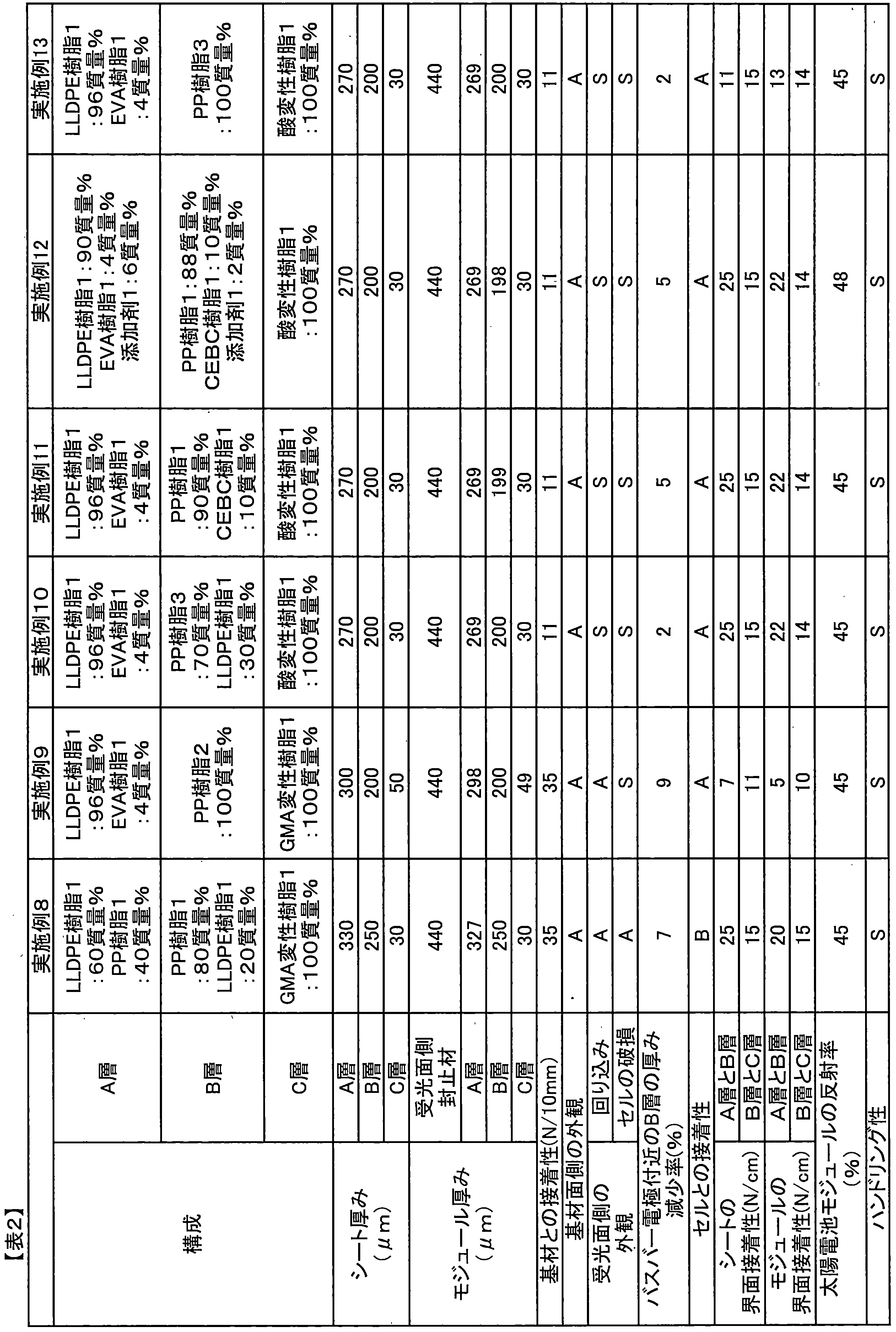
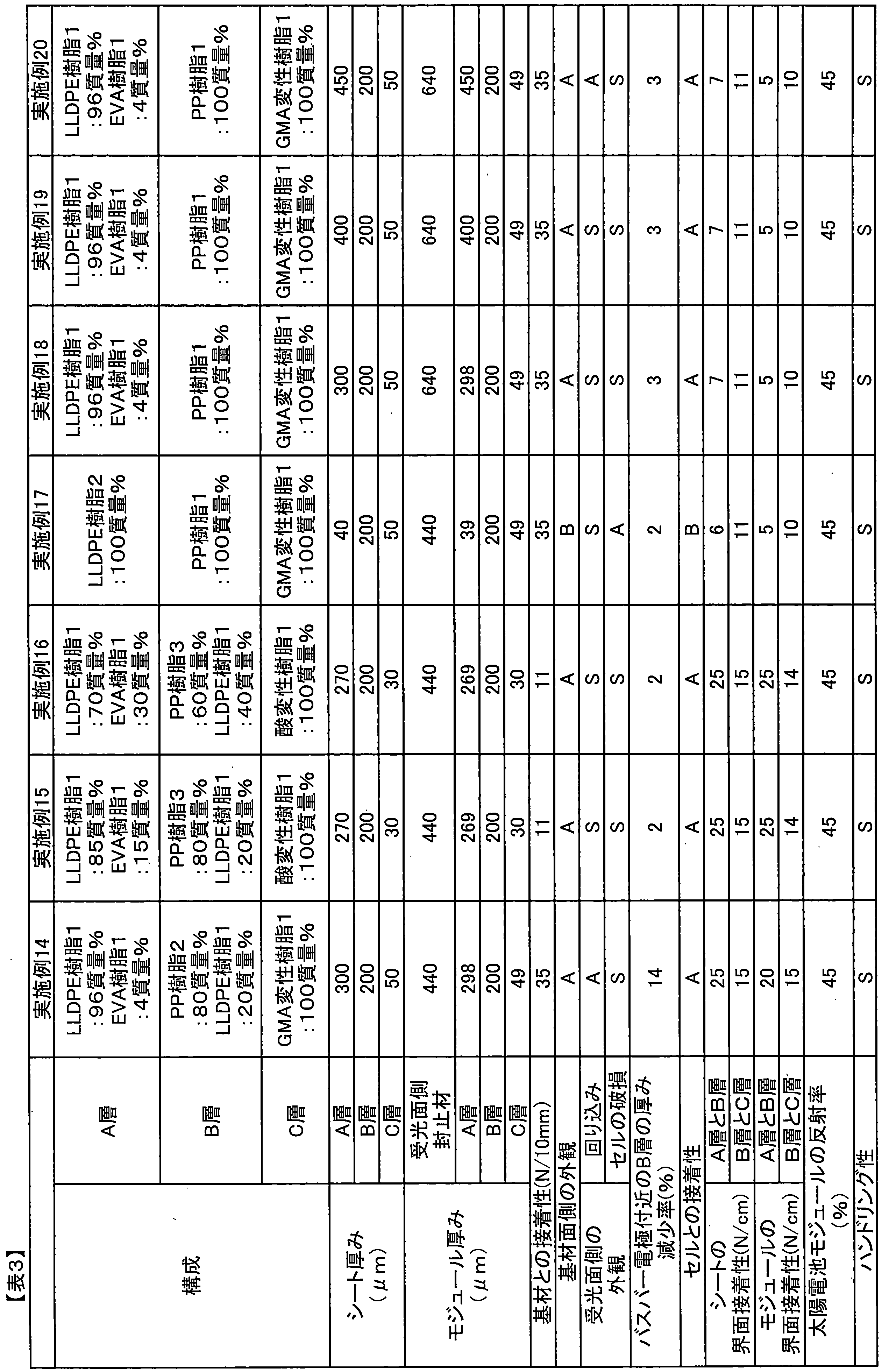
表4に示す通り、用いる樹脂や厚みを変えた以外は実施例1と同様の方法で多層シートを得て、基材との接着性、基材面側の外観、受光面側の外観、B層の厚み減少率、セルとの接着性、各層間の接着性や光線反射率を評価した。また、ハンドリング性も評価した。
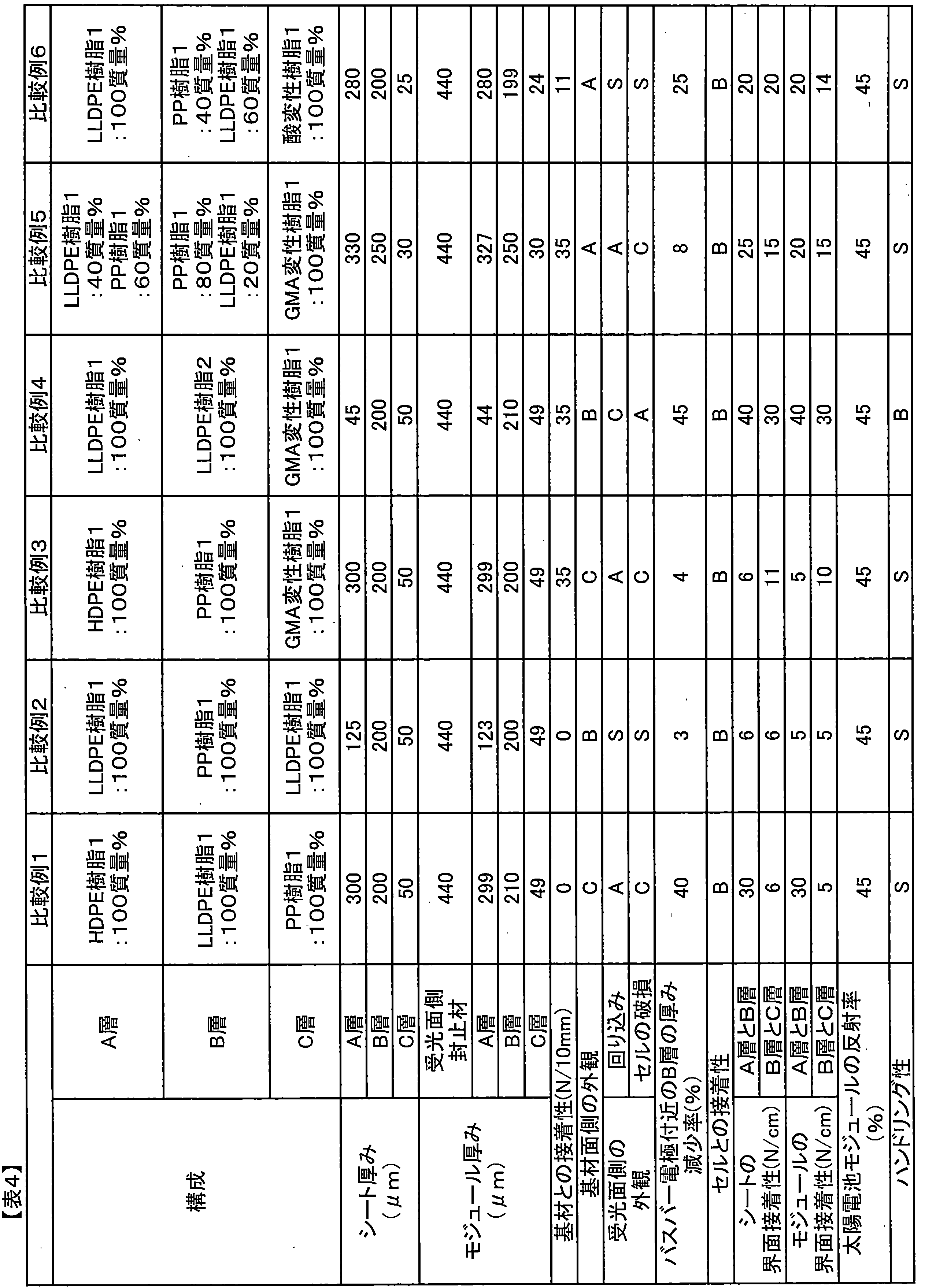
離型フィルム1を2枚用いて受光面側封止材1を挟み込み、油圧式熱プレス機を用いて100℃で加熱をしながら10MPaにて加圧し、その後室温に冷却し、離型フィルム1を剥がすことで、厚みが250μmの封止材を作成し、その後190mm×190mmにカットした。ガラス1、受光面側封止材1、セル1、得られた厚みが250μmの封止材、基材1の順に積層し、得られた厚みが250μmの封止材を積層する際のハンドリング性を評価したが、撓みやすくハンドリング性は悪かった。
2 受光面側封止材
3 セル
4 バスバー電極
5 A層
6 B層
7 C層
8 基材
9 太陽電池モジュールの反射率測定用の切断箇所
10 太陽電池モジュールの界面の接着強度測定用の切断箇所
11 太陽電池モジュールの各層の厚み測定用の切断箇所
12 太陽電池モジュールのB層の厚み減少率測定用の切断箇所
Claims (15)
- A層、B層、及びC層をこの順に有し、C層を一方の表面に有する太陽電池用多層シートであって、
A層は、層の全成分100質量%中に、融点が130℃未満のポリオレフィン系樹脂(A1)を50質量%を超え100質量%以下含む層であり、
B層は、層の全成分100質量%中に、融点が130℃以上であるポリオレフィン系樹脂(B1)を50質量%を超え100質量%以下含む層であり、
C層は、接着性樹脂を含む層であることを特徴とする、太陽電池用多層シート。 - A層の厚みが50μm以上500μm以下であることを特徴とする、請求項1に記載の太陽電池用多層シート。
- A層は、層の全成分100質量%中に、融点が130℃未満のポリオレフィン系樹脂(A1)を75質量%以上100質量%以下含む層であることを特徴とする、請求項1または2に記載の太陽電池用多層シート。
- B層中の融点が130℃以上であるポリオレフィン系樹脂(B1)の融点が、140℃以上であることを特徴とする、請求項1~3のいずれかに記載の太陽電池用多層シート。
- A層及びB層を、層間に他の層を介在することなく有し、
A層とB層の界面の接着強度が10N/cm以上であることを特徴とする、請求項1~4のいずれかに記載の太陽電池用多層シート。 - B層が、融点が130℃未満のポリオレフィン系樹脂(B2)を含むことを特徴とする、請求項1~5のいずれかに記載の太陽電池用多層シート。
- B層中の融点が130℃以上であるポリオレフィン系樹脂(B1)が、ブロックポリプロピレンであることを特徴とする、請求項1~6のいずれかに記載の太陽電池用多層シート。
- A層が接着性樹脂を含むことを特徴とする、請求項1~7のいずれかに記載の太陽電池用多層シート。
- A層に含まれる接着性樹脂は、エチレン-酢酸ビニル共重合体、エチレン-(メタ)アクリル酸脂肪族エステル共重合体、エチレン-グリシジルメタクリレート共重合体、エチレン-グリシジルメタクリレート-(メタ)アクリル酸脂肪族エステル共重合体、及びエチレン-グリシジルメタクリレート-酢酸ビニル共重合体からなる群より選ばれる少なくとも1つの樹脂であることを特徴とする、請求項8に記載の太陽電池用多層シート。
- B層は、リン原子を有する酸化防止剤を含むことを特徴とする、請求項1~9のいずれかに記載の太陽電池用多層シート。
- 請求項1~10のいずれかに記載の太陽電池用多層シートのC層側に、基材を有することを特徴とする、太陽電池用封止材一体型裏面保護シート。
- 請求項1~10のいずれかに記載の太陽電池用多層シートのA層側がセル側に、C層側が基材側に向くように、受光面保護基材、受光面側封止材、セル、太陽電池用多層シート、及び基材を、この順に配置して、真空ラミネートすることで得られる太陽電池モジュール。
- 受光面保護基材、受光面側封止材、セル、A層、B層、C層、及び基材をこの順に有し、
A層、B層、C層が以下の要件を満たし、太陽電池モジュールにおけるA層の厚さ(μm)をTAとして、TAが50μm以上500μm以下であることを特徴とする太陽電池モジュール。
A層は、層の全成分100質量%中に、融点が100℃以上130℃未満のポリオレフィン系樹脂(A1)を50質量%を超え100質量%以下含む層。
B層は、層の全成分100質量%中に、融点が130℃以上であるポリオレフィン系樹脂(B1)を50質量%を超え100質量%以下含む層。
C層は、接着性樹脂を含む層。 - 太陽電池モジュールにおけるA層の厚さ(μm)をTAとして、TAが50μm以上350μm以下であることを特徴とする、請求項13に記載の太陽電池モジュール。
- 受光面側封止材の厚さ(μm)をTとして、太陽電池モジュールにおけるA層の厚さ(μm)をTAとすると、以下の関係式を満たすことを特徴とする、請求項13または14に記載の太陽電池モジュール。
170≦T-TA≦600
Priority Applications (3)
| Application Number | Priority Date | Filing Date | Title |
|---|---|---|---|
| KR1020167006905A KR20160060041A (ko) | 2013-09-24 | 2014-09-18 | 태양 전지용 다층 시트, 태양 전지용 밀봉재 일체형 이면 보호 시트 및 태양 전지 모듈 |
| JP2014545988A JPWO2015046017A1 (ja) | 2013-09-24 | 2014-09-18 | 太陽電池用多層シート、太陽電池用封止材一体型裏面保護シート、及び、太陽電池モジュール |
| CN201480052610.4A CN105684162A (zh) | 2013-09-24 | 2014-09-18 | 太阳能电池用多层片、太阳能电池用密封材料一体型背面保护片、以及太阳能电池组件 |
Applications Claiming Priority (4)
| Application Number | Priority Date | Filing Date | Title |
|---|---|---|---|
| JP2013196578 | 2013-09-24 | ||
| JP2013-196578 | 2013-09-24 | ||
| JP2014065358 | 2014-03-27 | ||
| JP2014-065358 | 2014-03-27 |
Publications (1)
| Publication Number | Publication Date |
|---|---|
| WO2015046017A1 true WO2015046017A1 (ja) | 2015-04-02 |
Family
ID=52743156
Family Applications (1)
| Application Number | Title | Priority Date | Filing Date |
|---|---|---|---|
| PCT/JP2014/074714 Ceased WO2015046017A1 (ja) | 2013-09-24 | 2014-09-18 | 太陽電池用多層シート、太陽電池用封止材一体型裏面保護シート、及び、太陽電池モジュール |
Country Status (5)
| Country | Link |
|---|---|
| JP (1) | JPWO2015046017A1 (ja) |
| KR (1) | KR20160060041A (ja) |
| CN (1) | CN105684162A (ja) |
| TW (1) | TW201520049A (ja) |
| WO (1) | WO2015046017A1 (ja) |
Cited By (10)
| Publication number | Priority date | Publication date | Assignee | Title |
|---|---|---|---|---|
| WO2017006695A1 (ja) * | 2015-07-03 | 2017-01-12 | 大日本印刷株式会社 | 太陽電池モジュール用の封止材シート及びそれを用いてなる封止材一体型裏面保護シート |
| JP2017017257A (ja) * | 2015-07-03 | 2017-01-19 | 大日本印刷株式会社 | 太陽電池モジュール用封止材シート及びそれを用いてなる封止材一体型裏面保護シート |
| JP2017017261A (ja) * | 2015-07-03 | 2017-01-19 | 大日本印刷株式会社 | 太陽電池モジュール用の封止材一体型裏面保護シート及びそれを用いてなる太陽電池モジュール |
| JP2017017260A (ja) * | 2015-07-03 | 2017-01-19 | 大日本印刷株式会社 | 太陽電池モジュール用の封止材一体型裏面保護シート及びそれを用いてなる太陽電池モジュール |
| JP2017028035A (ja) * | 2015-07-17 | 2017-02-02 | 大日本印刷株式会社 | 太陽電池モジュール用の封止材一体型裏面保護シート及びそれを用いてなる太陽電池モジュール |
| JP2018518035A (ja) * | 2016-04-18 | 2018-07-05 | 蘇州賽伍応用技術有限公司Cybrid technologies inc. | 3層構造を有する共押出により一回成形する太陽電池モジュールバックシート |
| JP2018110161A (ja) * | 2016-12-28 | 2018-07-12 | 大日本印刷株式会社 | 太陽電池モジュール用の封止材一体型裏面保護シート、及び、それを用いてなる太陽電池モジュール |
| JP2021005729A (ja) * | 2020-10-01 | 2021-01-14 | 大日本印刷株式会社 | 太陽電池モジュール用の封止材一体型裏面保護シート、及び、それを用いてなる太陽電池モジュール |
| JP2021005730A (ja) * | 2020-10-01 | 2021-01-14 | 大日本印刷株式会社 | 太陽電池モジュール用の封止材一体型裏面保護シート、及び、それを用いてなる太陽電池モジュール |
| WO2025209411A1 (zh) * | 2024-04-02 | 2025-10-09 | 宁德时代新能源科技股份有限公司 | 钙钛矿光伏组件、用电装置、光伏系统以及发电装置 |
Families Citing this family (2)
| Publication number | Priority date | Publication date | Assignee | Title |
|---|---|---|---|---|
| JP2022124659A (ja) * | 2021-02-16 | 2022-08-26 | 日本航空電子工業株式会社 | モジュール及びその製造方法 |
| CN114907789B (zh) * | 2022-05-30 | 2023-11-21 | 常州百佳年代薄膜科技股份有限公司 | 三层高透非交联型光伏胶膜及其制备方法 |
Citations (6)
| Publication number | Priority date | Publication date | Assignee | Title |
|---|---|---|---|---|
| JP2007103738A (ja) * | 2005-10-05 | 2007-04-19 | Mitsui Chemicals Inc | 太陽電池封止材、太陽電池封止用シート、およびそれらを用いた太陽電池モジュール。 |
| JP2012015205A (ja) * | 2010-06-29 | 2012-01-19 | Japan Polyethylene Corp | 太陽電池モジュール、太陽電池封止材用組成物及びそれからなる太陽電池封止材 |
| WO2012017538A1 (ja) * | 2010-08-05 | 2012-02-09 | 三菱電機株式会社 | 太陽電池モジュールおよび太陽電池モジュールの製造方法 |
| JP2012222247A (ja) * | 2011-04-12 | 2012-11-12 | Kaneka Corp | 太陽電池封止材料およびこれを用いた太陽電池モジュール |
| WO2013021860A1 (ja) * | 2011-08-11 | 2013-02-14 | 東レ株式会社 | 積層シートおよびその製造方法 |
| JP2013065610A (ja) * | 2011-09-15 | 2013-04-11 | Dainippon Printing Co Ltd | 封止材組成物及びそれを用いた太陽電池モジュール用封止材 |
Family Cites Families (4)
| Publication number | Priority date | Publication date | Assignee | Title |
|---|---|---|---|---|
| US9040161B2 (en) * | 2010-03-26 | 2015-05-26 | Lintec Corporation | Protective sheet for solar cell module, and solar cell module |
| EP2579330B1 (en) * | 2010-06-03 | 2017-10-11 | Kaneka Corporation | Solar-cell backsheet and solar-cell module |
| JP5623325B2 (ja) * | 2011-03-30 | 2014-11-12 | リンテック株式会社 | 太陽電池用保護シートおよびその製造方法、ならびに太陽電池モジュール |
| WO2013003541A1 (en) * | 2011-06-30 | 2013-01-03 | Dow Global Technologies Llc | Multilayered polyolefin-based films having a layer comprising a crystalline block copolymer composite or a block copolymer composite resin |
-
2014
- 2014-09-18 CN CN201480052610.4A patent/CN105684162A/zh active Pending
- 2014-09-18 WO PCT/JP2014/074714 patent/WO2015046017A1/ja not_active Ceased
- 2014-09-18 JP JP2014545988A patent/JPWO2015046017A1/ja active Pending
- 2014-09-18 KR KR1020167006905A patent/KR20160060041A/ko not_active Withdrawn
- 2014-09-23 TW TW103132713A patent/TW201520049A/zh unknown
Patent Citations (6)
| Publication number | Priority date | Publication date | Assignee | Title |
|---|---|---|---|---|
| JP2007103738A (ja) * | 2005-10-05 | 2007-04-19 | Mitsui Chemicals Inc | 太陽電池封止材、太陽電池封止用シート、およびそれらを用いた太陽電池モジュール。 |
| JP2012015205A (ja) * | 2010-06-29 | 2012-01-19 | Japan Polyethylene Corp | 太陽電池モジュール、太陽電池封止材用組成物及びそれからなる太陽電池封止材 |
| WO2012017538A1 (ja) * | 2010-08-05 | 2012-02-09 | 三菱電機株式会社 | 太陽電池モジュールおよび太陽電池モジュールの製造方法 |
| JP2012222247A (ja) * | 2011-04-12 | 2012-11-12 | Kaneka Corp | 太陽電池封止材料およびこれを用いた太陽電池モジュール |
| WO2013021860A1 (ja) * | 2011-08-11 | 2013-02-14 | 東レ株式会社 | 積層シートおよびその製造方法 |
| JP2013065610A (ja) * | 2011-09-15 | 2013-04-11 | Dainippon Printing Co Ltd | 封止材組成物及びそれを用いた太陽電池モジュール用封止材 |
Cited By (11)
| Publication number | Priority date | Publication date | Assignee | Title |
|---|---|---|---|---|
| WO2017006695A1 (ja) * | 2015-07-03 | 2017-01-12 | 大日本印刷株式会社 | 太陽電池モジュール用の封止材シート及びそれを用いてなる封止材一体型裏面保護シート |
| JP2017017257A (ja) * | 2015-07-03 | 2017-01-19 | 大日本印刷株式会社 | 太陽電池モジュール用封止材シート及びそれを用いてなる封止材一体型裏面保護シート |
| JP2017017261A (ja) * | 2015-07-03 | 2017-01-19 | 大日本印刷株式会社 | 太陽電池モジュール用の封止材一体型裏面保護シート及びそれを用いてなる太陽電池モジュール |
| JP2017017260A (ja) * | 2015-07-03 | 2017-01-19 | 大日本印刷株式会社 | 太陽電池モジュール用の封止材一体型裏面保護シート及びそれを用いてなる太陽電池モジュール |
| JP2017028035A (ja) * | 2015-07-17 | 2017-02-02 | 大日本印刷株式会社 | 太陽電池モジュール用の封止材一体型裏面保護シート及びそれを用いてなる太陽電池モジュール |
| JP2018518035A (ja) * | 2016-04-18 | 2018-07-05 | 蘇州賽伍応用技術有限公司Cybrid technologies inc. | 3層構造を有する共押出により一回成形する太陽電池モジュールバックシート |
| JP2018110161A (ja) * | 2016-12-28 | 2018-07-12 | 大日本印刷株式会社 | 太陽電池モジュール用の封止材一体型裏面保護シート、及び、それを用いてなる太陽電池モジュール |
| JP2021005729A (ja) * | 2020-10-01 | 2021-01-14 | 大日本印刷株式会社 | 太陽電池モジュール用の封止材一体型裏面保護シート、及び、それを用いてなる太陽電池モジュール |
| JP2021005730A (ja) * | 2020-10-01 | 2021-01-14 | 大日本印刷株式会社 | 太陽電池モジュール用の封止材一体型裏面保護シート、及び、それを用いてなる太陽電池モジュール |
| JP7088255B2 (ja) | 2020-10-01 | 2022-06-21 | 大日本印刷株式会社 | 太陽電池モジュール用の封止材一体型裏面保護シート、及び、それを用いてなる太陽電池モジュール |
| WO2025209411A1 (zh) * | 2024-04-02 | 2025-10-09 | 宁德时代新能源科技股份有限公司 | 钙钛矿光伏组件、用电装置、光伏系统以及发电装置 |
Also Published As
| Publication number | Publication date |
|---|---|
| CN105684162A (zh) | 2016-06-15 |
| JPWO2015046017A1 (ja) | 2017-03-09 |
| TW201520049A (zh) | 2015-06-01 |
| KR20160060041A (ko) | 2016-05-27 |
Similar Documents
| Publication | Publication Date | Title |
|---|---|---|
| WO2015046017A1 (ja) | 太陽電池用多層シート、太陽電池用封止材一体型裏面保護シート、及び、太陽電池モジュール | |
| US10770609B2 (en) | Multilayered polyolefin-based films having a layer comprising a crystalline block copolymer composite or a block copolymer composite resin | |
| TWI504656B (zh) | 太陽電池密封材及使用其製作之太陽電池模組 | |
| US10759152B2 (en) | Multilayered polyolefin-based films having an integrated backsheet and encapsulation performance comprising a layer comprising crystalline block copolymer composite or block copolymer composite | |
| JP5952838B2 (ja) | 多層シート、太陽電池用バックシート及び太陽電池モジュール | |
| EP2346686B1 (en) | Co-extruded, multilayered polyolefin-based backsheet for electronic device modules | |
| TWI570948B (zh) | 太陽電池模組及其製造方法 | |
| TW201335262A (zh) | 外觀良好之太陽電池模組及其製造方法 | |
| TW201221571A (en) | Covering film for solar cell and solar cell module made using same | |
| JPWO2018180165A1 (ja) | 電池用積層体 | |
| JP2011049228A (ja) | 太陽電池モジュール用裏面一体化シート | |
| JP2015195338A (ja) | 太陽電池モジュールのリワーク方法 | |
| JP2016174072A (ja) | 太陽電池モジュール、及び太陽電池モジュールの製造方法 | |
| JP2011216653A (ja) | 太陽電池用接着シート | |
| JP2016225485A (ja) | 太陽電池用多層シート、太陽電池用封止材一体型裏面保護シート、及び、太陽電池モジュール | |
| JP6880631B2 (ja) | 太陽電池モジュール用の封止材一体型裏面保護シート、及び、それを用いてなる太陽電池モジュール | |
| JP2018035255A (ja) | 太陽電池モジュール用封止材、太陽電池モジュール用シート、太陽電池モジュールの製造方法、及び太陽電池モジュール | |
| JP2017130510A (ja) | 太陽電池モジュール用シート、及び太陽電池モジュール | |
| JP2015023089A (ja) | 太陽電池モジュール用積層体の製造方法 |
Legal Events
| Date | Code | Title | Description |
|---|---|---|---|
| ENP | Entry into the national phase |
Ref document number: 2014545988 Country of ref document: JP Kind code of ref document: A |
|
| 121 | Ep: the epo has been informed by wipo that ep was designated in this application |
Ref document number: 14847293 Country of ref document: EP Kind code of ref document: A1 |
|
| ENP | Entry into the national phase |
Ref document number: 20167006905 Country of ref document: KR Kind code of ref document: A |
|
| NENP | Non-entry into the national phase |
Ref country code: DE |
|
| 122 | Ep: pct application non-entry in european phase |
Ref document number: 14847293 Country of ref document: EP Kind code of ref document: A1 |