WO2015045646A1 - テープ貼付装置 - Google Patents
テープ貼付装置 Download PDFInfo
- Publication number
- WO2015045646A1 WO2015045646A1 PCT/JP2014/071038 JP2014071038W WO2015045646A1 WO 2015045646 A1 WO2015045646 A1 WO 2015045646A1 JP 2014071038 W JP2014071038 W JP 2014071038W WO 2015045646 A1 WO2015045646 A1 WO 2015045646A1
- Authority
- WO
- WIPO (PCT)
- Prior art keywords
- tape
- peeling
- adsorption
- mount
- desorption
- Prior art date
- Legal status (The legal status is an assumption and is not a legal conclusion. Google has not performed a legal analysis and makes no representation as to the accuracy of the status listed.)
- Ceased
Links
Images





Classifications
-
- B—PERFORMING OPERATIONS; TRANSPORTING
- B65—CONVEYING; PACKING; STORING; HANDLING THIN OR FILAMENTARY MATERIAL
- B65C—LABELLING OR TAGGING MACHINES, APPARATUS, OR PROCESSES
- B65C9/00—Details of labelling machines or apparatus
- B65C9/08—Label feeding
- B65C9/18—Label feeding from strips, e.g. from rolls
- B65C9/1865—Label feeding from strips, e.g. from rolls the labels adhering on a backing strip
-
- B—PERFORMING OPERATIONS; TRANSPORTING
- B65—CONVEYING; PACKING; STORING; HANDLING THIN OR FILAMENTARY MATERIAL
- B65C—LABELLING OR TAGGING MACHINES, APPARATUS, OR PROCESSES
- B65C9/00—Details of labelling machines or apparatus
- B65C9/0006—Removing backing sheets
- B65C2009/0009—Removing backing sheets by means of a peeling tip
Definitions
- the present invention relates to a tape applicator.
- Patent Document 1 a technique disclosed in Patent Document 1 is known as a conventional technique for peeling a label from a mount on which a label having a printing surface is attached.
- a strip-shaped mount on which a label having a printing surface is attached is bent to form a peeling end on the label.
- the label is positioned at the peeling position while holding the printing surface of the label.
- the mount is peeled off from the peeling end side of the label while holding the printing surface of the label.
- the label peeled in this way is attached to a member to be attached.
- Japanese Patent Publication Japanese Patent Laid-Open No. 2009-12851 (Published January 22, 2009)”
- the conventional technology as described above has a problem that it is difficult to peel the tape from the mount when the adhesive strength of the tape is high and the tape is weak (soft).
- the tension of the mount 106a is relatively weak
- the label 106b is bent together with the mount 106a when the strip 106a to which the label 106b having the printing surface is attached is bent.
- the mount 106a does not follow the tip of the peeling plate 140, and it becomes difficult to form the peeling edge on the label 106b. Therefore, it becomes impossible to peel the mount 106a from the label 106b while holding the printing surface of the label 106b by the suction pad 110.
- the present invention has been made in view of the above problems, and an object of the present invention is to provide a tape applicator provided with a peeling mechanism that can completely peel the tape from the mount even when the tape is weak. There is to do.
- a tape applicator includes a peeling mechanism that peels a tape from a mount on which the tape is stuck, and a tape that is peeled off by the peeling mechanism is attached to a member to be pasted.
- An adhering mechanism that adsorbs or desorbs the tape, and a pressing unit that presses the adsorbing / desorbing portion against the tape, and the peeling mechanism includes conveying means for conveying the mount Bending means for bending the mount to form a peeling end on the tape, and pressing the adsorbing / desorbing portion against the tape by the pressing portion, and the adsorbing / desorbing portion and the bending means to After maintaining the pinched state and forming the peeling end by the bending means, the board is lifted by the bending means while holding the tape by suction by the suction / desorption portion. It is characterized by peeling from the release end of the tape.
- the tape can be completely peeled from the mount even when the tape is weak.
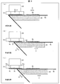
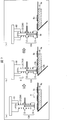
- FIGS. 3A to 3C are schematic side views schematically showing an example of a series of operations of a peeling plate when peeling a tape from a mount in the peeling mechanism of FIG. (A) to (c) are schematic side views showing the operation of the conveying means in conjunction with a series of operations of the peeling plate shown in (a) to (c) of FIG. 3 in the peeling mechanism.
- (A) to (c) schematically illustrate an example of a series of operations when peeling the tape from the mount when the area of the end surface facing the tape in the adsorption / desorption portion is smaller than the area of the printing surface of the tape. It is a schematic side view shown. It is sectional drawing which shows schematic structure of the peeling mechanism in the tape sticking apparatus which concerns on Embodiment 2 of this invention. (A)-(c) is a schematic sectional drawing which shows typically an example of a series of operation
- (A)-(d) is an example of a schematic structure of the sticking mechanism in the tape sticking apparatus according to Embodiment 2 of the present invention, and a series of operations when sticking the peeled tape to the sticking target member in the sticking mechanism.
- It is sectional drawing for demonstrating the problem of a prior art (a) is a figure explaining the problem of a prior art in case the tension of a mount is comparatively weak, (b) is the tension of a mount. The structure of the board
- FIG. 1 is an explanatory diagram illustrating a configuration of a control system in the tape applicator 100 according to the present embodiment.
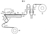
- FIG. 2 is a side view showing a schematic configuration of the peeling mechanism 101 in the tape applicator 100 according to the present embodiment.
- the tape sticking apparatus 100 includes a peeling mechanism 101, a sticking mechanism, an adsorption / desorption part 10, and a pressing part 20.
- the adsorption / desorption part 10 adsorbs or desorbs the tape 6b.
- the press part 20 presses the adsorption / desorption part 10 with respect to the tape 6b.
- the peeling mechanism 101 is a mechanism for peeling the tape 6b from the mount 6a to which the tape 6b is attached.
- the pasting mechanism is a mechanism for pasting the tape 6b peeled off by the peeling mechanism 101 to a member to be pasted.
- the peeling mechanism 101 peels the tape 6b from the mount 6a by pressing the adsorption / desorption part 10 against the tape 6b by the pressing part 20 and further adsorbing the tape 6b by the adsorption / desorption part 10.
- the sticking mechanism transfers the adsorption / desorption part 10 on which the tape 6b is adsorbed by the pressing part 20 to the application target member, and further presses it, and then attaches the tape 6b to the application target member by the attachment / detachment by the adsorption / desorption part 10. wear.
- the surface of the tape 6b on which the adsorption / desorption portion 10 is adsorbed is referred to as “surface 6e”.
- an exhaust driving unit 11 such as an exhaust pump or an air control device is attached to the adsorption / desorption unit 10.
- the adsorption / desorption unit 10 adsorbs or desorbs the tape 6b by turning on / off the exhaust by the exhaust driving unit 11.
- the pressing unit 20 is attached to, for example, a robot handling device having a transfer driving unit 21a and a pressing driving unit 21b.
- the pressing unit 20 is transferred to the pasting target member by the transfer driving unit 21a.
- the pressing part 20 presses the adsorption / desorption part 10 by the pressing drive part 21b.
- the pressing drive unit 21b may be a driving device such as an air cylinder.
- the peeling mechanism 101 includes a peeling plate 40 as a bending means and a conveying means for conveying the tape 6b attached to the mount 6a.
- the transport means includes a tape supply reel 32, a dancer fixed roller 33, a dancer 34, a fixed roller 35, a moving roller 36, a fixed roller 37, and a mount take-up reel 38.
- the tape 6b attached to the mount 6a (hereinafter referred to as a mount-attached tape) is first supplied to the tape supply reel 32 in a roll form.
- the tape with the mount wound by the tape supply reel 32 passes through the dancer fixed roller 33, the dancer 34, the fixed roller 35, the peeling plate 40, the moving roller 36, and the fixed roller 37, and is taken up by the mount take-up reel 38. . That is, between the tape supply reel 32 and the mount take-up reel 38, the belt-like mount 6a passes through the dancer fixed roller 33, the dancer 34, the fixed roller 35, the peeling plate 40, the moving roller 36, and the fixed roller 37. Is installed.
- a tape 6b is affixed to the surface of the mount 6a with a predetermined interval. Then, while being transported from the tape supply reel 32 to the mount take-up reel 38, the tape 6b is peeled off by the adsorption / desorption portion 10 and the release plate 40, and only the mount 7a is wound by the mount take-up reel 38. Taken.
- Various members (tape supply reel 32,... Mount winding reel 38) of the transport means are rotated by a transport drive unit 31 such as a motor. Therefore, the conveyance of the tape with the mount in the peeling mechanism 101 is controlled by the rotation of various members of the conveyance unit by the conveyance drive unit 31.
- the peeling plate 40 is disposed in the conveyance path of the mount 6a between the unwinding roller 30a and the winding roller 30b.
- the release plate 40 is a bending means that can peel the tape 6b from the mount 6a by bending the mount 6a.
- the peeling plate 40 is disposed substantially parallel to the transport direction of the mount 6a, and the mount support portion 40a that supports the back surface of the mount 6a, and the mount bend disposed in front of the mount support portion 40a in the transport direction of the mount 6a. Part 40b. Further, the peeling plate 40 is moved forward or backward in the carrying direction of the mount 6a by a peeling plate moving drive unit 41 such as an air cylinder.
- an edge 40c is formed on the mount bending portion 40b of the release plate 40 so as to extend along the width direction of the mount 6a.
- the edge 40c can smoothly slide with respect to the back surface of the mount 6a when the mount 6a is taken up by the take-up roller 30b, and uses the tension in the conveying direction that acts on the mount 6a when the mount 6a is taken up.
- the mount 6a can be bent at an angle of about 155 degrees with respect to the peeling surface 6d of the tape 6b.
- the tension acting on the mount 6a is controlled by the operations of the dancer fixed roller 33 and the dancer 34, and the operations of the fixed roller 35, the peeling plate 40, the moving roller 36, and the fixed roller 37.
- the peeling mechanism 101 includes a dancer fixed roller 33 and a dancer 34, a fixed roller 35, a peeling plate 40, a moving roller 36, and a fixed roller 37 as tension applying means for applying a predetermined tension to the mount 6a during the peeling operation. I have.
- the angle at which the mount 6a is bent can be appropriately adjusted to, for example, an angle of 90 to 170 degrees by changing the dimensional shape of the mount bending portion 40b of the release plate 40. Further, by changing the size and shape of the edge 40c of the mount bending portion 40b, the shape of the edge 40c is adjusted so as to conform to the thickness and elasticity of the mount 6a and the tape 6b or the tension in the transport direction acting on the mount 6a. Can be adjusted. For example, when the thickness of the mount is 0.1 mm or less, an acute arcuate surface or elliptical arcuate surface corresponding to a radius of 0.1 mm (R0.1) to 0.3 mm (R0.3) is used. It is desirable to form the edge 40c so as to have a curved surface.
- the adsorption / desorption portion 10 and the pressing portion 20 are arranged at a predetermined position (hereinafter referred to as a peeling position) corresponding to the position of the tape 6b when peeling the tape 6b from the mount 6a.
- the adsorption / desorption part 10 has a plurality of adsorption parts 10a connected to the exhaust drive part 11 described above, and can adsorb and hold the surface 6e of the tape 6b by these adsorption parts 10a.
- the shape and size of the adsorption / desorption portion 10 and the size, number, arrangement, suction force, etc. of the adsorption portion 10a can be appropriately selected according to the size of the tape 6b.
- the pressing portion 20 is advanced or retracted in the direction of the arrow 9 by the above-described pressing driving portion 21b. As a result, the pressing portion 20 is pressed against the adsorption / desorption portion 10.
- the control unit 50 is a computer device that includes an arithmetic processing unit such as a CPU and a dedicated processor, and a storage unit (not shown) such as a RAM, a ROM, and an HDD, and is stored in the storage unit.
- an arithmetic processing unit such as a CPU and a dedicated processor
- a storage unit such as a RAM, a ROM, and an HDD
- each part (exhaust drive unit 11, transfer drive unit 21a, press drive unit 21b, transport drive unit 31, release plate) of the tape applying apparatus 100 is executed.
- the movement drive unit 41 and the like are controlled, and the tape 6b peeling process or the tape 6b sticking process is performed by the adsorption / desorption part 10, the pressing part 20, the peeling mechanism 101, the sticking mechanism, and the like.
- FIGS. 3A to 3C are schematic side views schematically showing an example of a series of operations of the peeling plate 40 when peeling the tape 6b from the mount 6a in the peeling mechanism 101.
- FIG. 4A to 4C are schematic side views showing the operation of the conveying means in conjunction with the series of operations of the peeling plate 40 shown in FIGS. 3A to 3C in the peeling mechanism 101.
- FIG. FIG. In FIGS. 3A to 3C, illustration of the means for transporting the tape with mount is omitted.
- 4A to 4C illustration of the tape supply reel 32, the dancer fixing roller 33, the dancer 34, and the mount take-up reel 38 is omitted.
- the control unit 50 controls the operation of the transport driving unit 31 to rotate the tape supply reel 32 and the mount take-up reel 38, thereby attaching the tape 6 b.
- the mounted mount 6 a is unwound from the tape supply reel 32.
- the unwound mount 6a is conveyed in the direction of arrow A, and is bent by the peeling plate 40 when the tape 6b to be peeled reaches the peeling position shown in FIG.
- the control unit 50 controls the operation of the transport driving unit 31 to stop the rotation of the unwind roller 30a, and stops the transport of the mount 6a. Thereafter, the tape 6b itself can be further positioned as necessary.
- the control unit 50 controls the operation of the pressing drive unit 21b and moves the pressing unit 20 in the direction of the arrow 9 to lower the adsorption / desorption part 10. . And even after the adsorption
- the control unit 50 controls the transfer driving unit 21a to stop the pressing by the pressing unit 20.
- the pressing portion 20 presses the tape 6b against the peeling plate 40 with a predetermined pressure, and causes the adsorption / desorption portion 10 to follow the tape 6b.
- the mount 6a does not float from the release plate 40 at the edge 40c of the release plate 40.
- control unit 50 controls the operation of the exhaust driving unit 11 to be off. For this reason, the adsorption / desorption part 10 does not adsorb the tape 6b.
- the control unit 50 drives the transport driving unit 31 and the peeling plate movement.
- the part 41 is controlled to form the peeling end 6c with respect to the tape 6b at the peeling position. More specifically, first, the control unit 50 controls the operation of the transport driving unit 31 to rotate various members of the transport unit to apply tension to the tape with mount.
- the mount 6a is bent along the edge 40c of the peeling plate 40. For example, tension can be applied to the tape with mount by the operation of the dancer fixing roller 33 and the dancer 34.
- the tensioner moves the dancer 34 upward.
- tension can be applied to the tape with mount.
- the separation plate 40 and the moving roller 36 are integrally operated between the fixed roller 35 and the fixed roller 37, and the length of the mount 6a between the fixed roller 35 and the fixed roller 37 is made constant. Even if the peeling plate 40 moves, a stable tension can be applied to the tape with mount.
- control unit 50 controls the operation of the peeling plate movement drive unit 41 in a state where the tension is applied to the tape with the mount in this way, and moves the peeling plate 40 backward in the direction of the arrow C.
- the mount 6a is bent by the mount bending portion 40b of the release plate 40 in the vicinity of the release position.
- the bending angle ⁇ of the mount 6a with respect to the peeling surface 6d of the tape 6b is about 155 °.
- the tape 6b in the peeling position is vacuum-sucked by the adsorption / desorption part 10 and is sandwiched between the peeling plate 40 and the adsorption / desorption part 10, it does not bend together with the mount 6a.
- a part of the tape 6b to be peeled in front of the transport direction is peeled off, and a peeling end 6c is formed on the tape 6b.
- control unit 50 controls the operation of the exhaust driving unit 11 to be on. For this reason, the adsorption / desorption part 10 adsorbs the tape 6b.
- the holding of the tape 6b is performed by sucking and sucking the air at the two locations in the front and rear of the tape 6b in the transport direction through the suction section 10a of the suction / desorption section 10 by the exhaust driving section 11.
- suction part 10a may be provided in several places, and may raise adsorption
- control unit 50 drives the conveyance driving unit 31 and the peeling plate while holding the surface 6e of the tape 6b by the adsorption / desorption unit 10.
- the part 41 is controlled to peel the tape 6b from the mount 6a (see (c) in FIG. 3 and (c) in FIG. 4).
- control unit 50 controls the operation of the peeling plate movement driving unit 41 to move the peeling plate 40 backward in the direction of arrow C.
- the moving roller 36 also moves together with the peeling plate 40.
- the tape 6b to be peeled is peeled from the peeling end 6c side and finally peeled completely from the mount 6a.
- the control unit 50 moves the peeling plate 40 back to the original position and controls the operation of the transport driving unit 31 to rotate the mount take-up reel 38, thereby causing the tape 6b to move.
- the backing paper 6a after being peeled off is taken up by the take-up roller 30b.
- the control unit 50 controls the operation of the transfer drive unit 21a and / or the press drive unit 21b, moves the peeled tape 6b to the application target member, and the desired position of the application target member by the application mechanism described above. Paste to.
- the peeling mechanism 101 of the tape applying device 100 presses the adsorption / desorption portion 10 against the tape 6b by the pressing portion 20 and keeps the tape 6b sandwiched between the adsorption / desorption portion 10 and the peeling plate 40, After the peeling end 6c is formed by the peeling plate 40, the mount 6a is peeled from the peeling end 8c side of the tape 6b by the peeling plate 40 while holding the surface 6e of the tape 6b by suction by the suction / desorption portion 10. .
- the peeling end 6c is formed with respect to the tape 6b by the peeling plate 40 in a state where the tape 6b is sandwiched between the peeling plate 40 and the adsorption / desorption portion 10, even if the waist of the tape 6b is weak, The tape 6b does not bend together with the mount 6a. Therefore, even if the waist of the tape 6b is weak, the peeling end 6c can be formed with respect to the tape 6b. Therefore, the tape 6b can be peeled off from the peeling end 6c side and completely peeled off from the mount 6a. it can.
- the peeling mechanism 101 of the tape applying apparatus 100 performs the peeling operation of the tape 6b while pressing the tape 6b against the peeling plate 40 by the pressing portion 20 and causing the adsorption / desorption portion 10 to follow the tape 6b. Is going. For this reason, even if it is the tape 6b with a weak waist, a peeling end can be formed reliably, the tape 6b can be peeled from the peeling end 6c side, and it can peel completely from the base_sheet
- the pressing part 20 presses the tape 6b so that the adsorption / desorption part 10 overhangs the edge of the tape 6b.
- the end of the adsorption / desorption portion 10 in the transport direction (the direction of arrow A) is disposed outside the peeling plate 40 and the tape 6b in the conveyance direction. ing.
- the tape 6b can be made to follow the adsorption / desorption portion 10, and the tape 6b does not follow the mount 6a at the edge of the peeling plate 40 (the tape 6b is cut at the edge of the peeling plate 40). It does not bend together with the mount 6a).
- the peeling end 6c can be more reliably formed with respect to the tape 6b.
- FIGS. 5A to 5C show a case where the tape 6b is peeled from the mount 6a when the end surface 10b of the adsorption / desorption portion 10 facing the tape 6b does not overhang with respect to the edge of the tape 6b. It is a schematic side view which shows typically an example of a series of operation
- FIGS. 5A to 5C in the end surface 10b of the adsorption / desorption portion 10, when the end surface 10b does not overhang with respect to the edge of the tape 6b, the end of the tape 6b in the transport direction is transported. In this case, the edge of the peeling plate 40 is applied before the adsorption / desorption portion 10.
- the tape 6b is peeled from the mount 6a. Instead, it may be sent to the mount take-up reel 38 together with the mount 6a and discarded. As a result, as shown in FIG. 5C, the tape 6b to be peeled may not be adsorbed by the adsorption / desorption unit 10 and may not be held by the adsorption / desorption unit 10.
- FIG. 6 is a cross-sectional view showing a schematic configuration of the peeling mechanism 101A in the tape applying apparatus according to the present embodiment.
- FIGS. 7A to 7C are schematic cross-sectional views schematically showing an example of a series of operations when peeling the tape 6b from the mount 6a in the peeling mechanism 101A.
- 8A to 8D show a schematic configuration of the sticking mechanism 102 in the tape sticking apparatus of the present embodiment, and when the peeled tape 6b is stuck to the sticking target member 70 in the sticking mechanism 102.
- the tape applicator of the present embodiment is different from the tape applicator 100 of the first embodiment in the configuration of the adsorption / desorption unit, the pressing unit, and the application mechanism.
- the adsorption / desorption part 10 ⁇ / b> A is constituted by an adsorption / desorption part main body 12 and an outer peripheral member 13 surrounding the outer periphery of the adsorption / desorption part main body 12.
- the adsorption / desorption portion 10 ⁇ / b> A can be divided into an adsorption / desorption portion main body 12 and an outer peripheral member 13.
- the pressing portion 20A includes a pressing spring 22 that presses the adsorption / desorption portion 10A.
- the adsorption / desorption unit main body 12 is attached to, for example, a handling unit 60 of a robot, and the exhaust hole 12a as the adsorption unit described above is formed therein.
- the adsorption / desorption unit main body 12 is provided with an exhaust pipe 14 connected to the exhaust drive unit 11 described above.
- the exhaust hole 12a and the exhaust pipe 14 are configured to communicate with each other.
- the outer circumferential member 13 is formed with an insertion hole 13a into which the adsorption / desorption portion main body 12 is inserted.
- the pressing spring 22 is in contact with the upper surface 13c of the outer peripheral member 13 opposite to the tape 6b, and is arranged so as to press the outer peripheral member 13 in the direction of the arrow 9.
- the end surface 12b and the end surface 13b facing the tape 6b in the adsorption / desorption portion main body 12 and the outer peripheral member 13 are flush with both the adsorption / desorption portion main body 12 and the outer peripheral member 13, or one of them.
- a locking portion (not shown) for locking is provided. Therefore, in the tape applicator according to this embodiment, when a force in the direction opposite to the arrow 9 is applied from the end face 13b side of the outer peripheral member 13, only the outer peripheral member 13 of the adsorption / desorption portion main body 12 and the outer peripheral member 13 is an arrow. 9 is moved in the opposite direction.
- the control unit 50 controls the operation of the transport driving unit 31 to rotate the unwinding roller, thereby unwinding the mount 6a to which the tape 6b is attached. Unwind from the roller 30a.
- the unwound mount 6a is conveyed in the direction of arrow A, and is bent by the peeling plate 40 when the tape 6b to be peeled reaches the peeling position shown in FIG.
- the control unit 50 controls the operation of the transport driving unit 31 to stop the rotation of the unwind roller 30a, and stops the transport of the mount 6a.
- the control unit 50 stops the tape 6b to be peeled off at the peeling position, and then controls the operation of the pressing drive unit 21b so that the pressing spring 22 is attached.
- the adsorption / desorption part 10A is lowered, and the adsorption / desorption part 10A is brought into contact with the tape 6b at the peeling position.
- both the end surface 12b of the adsorption / desorption portion main body 12 and the end surface 13b of the outer peripheral member 13 are in contact with the tape 6b.
- control part 50 controls the press drive part 21b, and presses the pressing spring 22 with respect to the adsorption
- suction removal parts contact the tape 6b in a peeling position.
- the control unit 50 controls the transfer driving unit 21a to stop the pressing by the pressing unit 20A.
- control unit 50 controls the transport driving unit 31 and the peeling plate movement driving unit 41 to form a peeling end with respect to the tape 6b at the peeling position. Since the operation for forming the peeling end is the same as that in FIG.
- control unit 50 controls the operation of the exhaust driving unit 11 to be on, and adsorbs and holds the tape 6b by the adsorption / desorption unit 10A. And the conveyance drive part 31 and the peeling plate movement drive part 41 are controlled, and the tape 6b of peeling object is peeled from the peeling end side.
- the operation of peeling the tape 6b is the same as that shown in FIG.
- the tape 6b to be peeled held by the adsorption / desorption portion 10A is completely peeled from the mount 6a. Further, the mount 6a after the tape 6b is peeled off is taken up by the take-up roller 30b.
- the control unit 50 controls the operation of the transfer drive unit 21a and / or the press drive unit 21b, moves the peeled tape 6b to the application target member, and moves the tape 6b to the desired position of the application target member 70 by the application mechanism 102. paste.
- the sticking mechanism 102 includes a holding body 80 that holds the sticking target member 70.
- the holding body 80 includes a wall portion 81 and a base portion 82.
- the wall 81 is held in contact with the side surface 70 c of the pasting target member 70.
- substrate part 82 supports the lower surface 70b on the opposite side to the sticking surface 70a which affixes the tape 6b in the sticking object member 70.
- the wall portion 81 protrudes above the sticking surface 70a of the sticking target member 70, and is provided so as to abut only the outer peripheral member 13 of the adsorption / desorption portion main body 12 and the outer peripheral member 13 when the tape 6b is stuck. It has been.
- the sticking target member 70 held by the holding body 80 is disposed at a predetermined position (hereinafter referred to as a sticking position) of the sticking target member 70 when the sticking surface 70a is exposed upward and the tape 6b is stuck. ing.
- the control unit 50 controls the operation of the transfer driving unit 21a to move the pressing spring 22 and the adsorption / desorption unit 10A attached to the handling unit 60. .
- the movement of the transfer drive portion 21a is controlled to stop the movement of the pressing spring 22 and the adsorption / desorption portion 10A. Thereafter, the tape 6b itself can be further positioned as necessary.
- the controller 50 controls the operation of the pressing drive unit 21b after stopping the tape 6b at the application position, and moves the pressing spring 22 in the direction of the arrow 9 to lower the adsorption / desorption unit 10A.
- the adsorption / desorption portion 10A is lowered in this way, only the tape 6b on the outer peripheral member 13 out of the adsorption / desorption portion main body 12 and the outer peripheral member 13 becomes the wall of the holding body 80 as shown in FIG. It abuts on the part 81.
- the control unit 50 controls the pressing drive unit 21b even after only the tape 6b on the outer peripheral member 13 abuts against the wall portion 81 of the holding body 80, and the pressing spring. 22 is pressed against the adsorption / desorption portion 10A.
- the wall portion 81 of the holding body 80 is pressed against the outer peripheral member 13 in the direction opposite to the arrow 9.
- a force in the direction opposite to the arrow 9 is applied to the outer peripheral member 13, and the pressing spring 22 contracts.
- only the outer peripheral member 13 of the adsorption / desorption portion main body 12 and the outer peripheral member 13 moves in the direction opposite to the arrow 9.
- the adsorption / desorption unit main body 12 moves in the direction of the arrow 9 by driving the transfer driving unit 21 a and presses the pasting target member 70.
- the tape 6 b is sandwiched between the adsorption / desorption portion main body 12 and the pasting target member 70 and disposed on the pasting surface 70 a of the pasting target member 70.
- the control unit 50 controls the operation of the exhaust driving unit 11 to be off, and detaches the tape 6b from the adsorption / desorption unit 10A.
- the tape 6b held by the adsorption / desorption portion 10A is attached to the application surface 70a of the application target member 70.
- control part 50 controls the operation
- the adsorption / desorption portion 10A is configured by being divided by the adsorption / desorption portion main body 12 and the outer peripheral member 13 surrounding the outer periphery of the adsorption / desorption portion main body 12.
- the suction / desorption part main body 12 and the outer peripheral member 13 are both pressed against the tape 6b by the pressing part 20A while keeping the state in contact with the tape 6b.
- the suction / desorption part main body 12 is kept protruding from the outer peripheral member 13, and the suction part 20A is attached to the tape 6b by the pressing part 20A.
- the main body 12 is pressed.
- the tape 6b can be peeled from the peeling end 6c side and can be completely peeled off from the mount 6a, and the tape 6b can be securely attached to the sticking surface of the member 70 to be stuck. It can be attached to 70a.
- the tape sticking device according to the present embodiment is effective.
- the controller 50 of the tape applicator 100 may be realized by a logic circuit (hardware) formed in an integrated circuit (IC chip) or the like, or may be realized by software using a CPU (Central Processing Unit). Good.
- a logic circuit hardware
- IC chip integrated circuit
- CPU Central Processing Unit
- the tape applicator 100 includes a CPU that executes instructions of a program that is software for realizing each function, and a ROM (Read (Only Memory) in which the program and various data are recorded so as to be readable by a computer (or CPU).
- a storage device (these are referred to as “recording media”), a RAM (Random Access Memory) for expanding the program, and the like are provided.
- the objective of this invention is achieved when a computer (or CPU) reads the said program from the said recording medium and runs it.
- a “non-temporary tangible medium” such as a tape, a disk, a card, a semiconductor memory, a programmable logic circuit, or the like can be used.
- the program may be supplied to the computer via an arbitrary transmission medium (such as a communication network or a broadcast wave) that can transmit the program.
- a transmission medium such as a communication network or a broadcast wave
- the present invention can also be realized in the form of a data signal embedded in a carrier wave in which the program is embodied by electronic transmission.
- the tape 6b may be configured to be affixed to the mount 6a, and can be appropriately applied depending on the type of the member 70 to be affixed to the tape 6b.
- the sticking target member 70 is a liquid crystal module (a combination of a liquid crystal panel and a backlight)
- a bezelless tape is preferably used as the tape 6b.
- the bezelless tape is a tape that is attached to the outer periphery of the liquid crystal module.
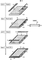
- FIG. 9 is a perspective view showing a process of attaching the bezelless tape to the liquid crystal module.
- FIG. 10 is a top view showing a process of attaching the bezelless tape to the liquid crystal module.
- movement demonstrated below is controlled by the control part 50 of the tape sticking apparatus 100 mentioned above.
- the liquid crystal module 200 as a member to be pasted is a combination of a liquid crystal panel 202 and a backlight (not shown).
- a polarizing plate 201 is provided on the display surface of the liquid crystal panel 202.
- the long side tape 6 c is applied to the long side portion of the liquid crystal module 200.
- an operation of integrating the liquid crystal panel 200 and the backlight (not shown) is performed by bending the long side tape 6 c so as to wrap the liquid crystal module 200 in the long side portion.
- the short side tape 6d is applied to the short side portion of the liquid crystal module 200.
- the operation of integrating the liquid crystal panel 200 and the backlight (not shown) is performed by bending the short side tape 6d so as to wrap the liquid crystal module 200 at the short side portion.
- the liquid crystal module 200 to which the bezelless tape (the long side tape 6c and the short side tape 6d) is attached is thinner than the conventional liquid crystal module in which a metal frame-shaped member is provided at the peripheral portion. be able to.
- the bezel-less tape is made of a polyethylene terephthalate (PET) film or a metal foil made of aluminum or copper. Therefore, the bezelless tape is weak and has high adhesive strength to the mount. Therefore, in the conventional tape peeling apparatus, it is difficult to form a peeling end that triggers peeling of the bezelless tape from the mount.
- PET polyethylene terephthalate
- metal foil made of aluminum or copper. Therefore, the bezelless tape is weak and has high adhesive strength to the mount. Therefore, in the conventional tape peeling apparatus, it is difficult to form a peeling end that triggers peeling of the bezelless tape from the mount.
- the peeling end can be formed on the tape by the peeling mechanism 101, so that the bezelless tape can be peeled from the mount. It is.
- the tape 6b applicable to the present invention is not limited to a bezelless tape, and may be a label having a printing surface.
- the tape applicator 100 is provided with the peeling mechanisms 101 and 101A for peeling the tape 6b from the mount 6a to which the tape 6b is stuck, and the tape 6b peeled by the peeling mechanism 101 to the sticking target member 70.
- the peeling mechanisms 101 and 101A include conveying means (unwinding roller 30a and take-up roller 30b) for conveying the mount 6a, and bending means (peeling plate) for bending the mount 6a to form a peeling end 6c on the tape 6b. 40), and the adsorption / desorption portions 10 and 10A are pressed against the tape 6b by the pressing portions 20 and 20A.
- the tape 6b is adsorbed by 10A, and the tape 6b is held between the adsorption / desorption portions 10, 10A and the bending means (peeling plate 40), and the mount is made by the bending means (peeling plate 40). 6a is peeled off from the peeling end 6c side of the tape 6b.
- the said tape 6b is adsorbed by the said adsorption / desorption part 10, 10A, and a peeling end is formed with respect to a tape by the said bending means in the state clamped by the said bending means and the said adsorption / desorption part. Therefore, even if the area of the entire tape is large (the tape is weak) with respect to the pasting region to be pasted on the pasting target member, the tape does not bend together with the mount. Therefore, even if the tape is weak, a peeling end can be formed on the tape, so that the tape can be peeled from the peeling end side and completely peeled off from the mount.
- the end of the adsorption / desorption portion 10, 10A in the board transport direction is the direction of the tape mount (the arrow A). It is preferable to pass the tip of the bending means before the end in the direction.
- the peeling mechanism 101 includes tension applying means (a dancer fixing roller 33, a dancer 34, a fixing roller 35, a tension applying means for applying a predetermined tension to the mount 6a during a peeling operation.
- tension applying means a dancer fixing roller 33, a dancer 34, a fixing roller 35, a tension applying means for applying a predetermined tension to the mount 6a during a peeling operation.
- a release plate 40, a moving roller 36, and a fixed roller 37 are preferably provided.
- the tape 6b can be more completely peeled from the mount 6a more reliably.
- the adsorption / desorption part 10A is constituted by the adsorption / desorption part main body 12 and the outer peripheral member 13 surrounding the outer periphery of the adsorption / desorption part main body 12.
- both the adsorption / desorption portion main body 12 and the outer peripheral member 13 are kept in contact with the tape 6b, and the pressing portion 20A While pressing against the tape 6b, when sticking the tape 6b peeled by the sticking mechanism 102 to the sticking target member 70, keep the state where the adsorption / desorption portion main body 12 protrudes from the outer peripheral member 13, The adsorption / desorption portion main body 12 is pressed against the tape 6b by the pressing portion 20A. Preferred.
- the tape sticking device According to the above configuration, even when the tape is weak, the tape can be peeled off from the peeling end side and completely peeled off from the mount, and the tape can be securely attached to the sticking surface of the member to be pasted. Can.
- the tape sticking device when the area of the sticking surface of the sticking target member is extremely small with respect to the tape, the tape sticking device according to this embodiment is effective.
- the pressing portion 20A preferably includes an elastic member (pressing spring 22) for pressing the adsorption / desorption portion 10A.
- the pressing operation by the pressing portion can be simplified.
- the bending means includes a mount support portion 40a that supports the back surface of the mount 6a, and the transport direction of the mount 6a rather than the mount support portion 40a.
- the peeling board 40 which has the mount bending part 40b arrange
- peeling mechanism 101,101A is the said tape 6b by the said adsorption / desorption part 10, 10A and the said bending means (peeling board 40). While maintaining the state of holding the sheet, the mount 6a is moved in the transport direction (direction of arrow B) and the bending means (peeling plate 40) is moved backward in the direction opposite to the transport direction (direction of arrow C). Therefore, it is preferable to form the peeling end 6c on the tape 6b.
- the present invention can be used for all techniques for peeling a tape from a mount and sticking the peeled tape to a member to be pasted.
Landscapes
- Folding Of Thin Sheet-Like Materials, Special Discharging Devices, And Others (AREA)
- Labeling Devices (AREA)
Abstract
テープの腰が弱い場合であっても、完全に台紙からテープを剥離するため、本発明のテープ貼付装置における剥離機構(101)は、吸着脱着部(10)と剥離板(40)とによりテープ(6b)を挟持した状態を保って、剥離板(40)によって剥離端(6c)を形成した後に、吸着脱着部(10)によってテープ(6b)を保持したまま剥離板(40)により台紙(6a)を剥離端(6c)側から剥離する。
Description
本発明は、テープ貼付装置に関する。
印刷面を有するラベルが貼付された台紙からラベルを剥離する従来技術として、例えば特許文献1に開示された技術が知られている。特許文献1の技術では、まず、印刷面を有するラベルが貼付された帯状の台紙を曲げてラベルに剥離端を形成する。そして、ラベルに剥離端を形成した後、ラベルの印刷面を保持してラベルを剥離位置に位置決めする。そして、ラベルの印刷面を保持したまま台紙をラベルの剥離端側から剥離している。このように剥離されたラベルは、貼付対象部材に貼り付けられる。
しかしながら、上述のような従来技術では、テープの台紙に対する粘着力が高くテープの腰が弱い(軟らかい)場合、台紙からテープを剥離することが困難であるという問題がある。
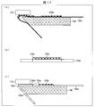
図11の(a)に示されるように、台紙106aのテンションが比較的弱い場合、印刷面を有するラベル106bが貼付された帯状の台紙106aを曲げるに際し、ラベル106bは、台紙106aとともに曲がってしまう。その結果、台紙106aが剥離板140の先端に倣わず、ラベル106bに剥離端を形成することが困難になる。それゆえ、吸着パッド110によってラベル106bの印刷面を保持したまま台紙106aをラベル106bから剥離することができなくなる。
また、台紙106aのテンションが比較的強い場合、図11の(b)に示されるように、出し106aにハーフカット106cを形成し、テンションを調整する方策が考えられる。しかし、この場合、図11の(c)に示されるように、台紙106bにハーフカット106cが形成されているため、台紙106aが剥離板140のエッジ部に引っ掛かる。このため、ラベル106bに剥離端を形成することが困難になる。
本発明は、上記問題に鑑みなされたものであり、その目的は、テープの腰が弱い場合であっても、完全に台紙からテープを剥離することができる剥離機構を備えたテープ貼付装置を提供することにある。
上記の課題を解決するために、本発明の一態様に係るテープ貼付装置は、テープが貼付された台紙からテープを剥離する剥離機構と、上記剥離機構によって剥離されたテープを貼付対象部材へ貼付ける貼付機構と、上記テープを吸着する、あるいは脱着する吸着脱着部と、上記テープに対し上記吸着脱着部を押圧する押圧部と、を備え、上記剥離機構は、上記台紙を搬送する搬送手段と、上記台紙を曲げて上記テープに剥離端を形成する曲げ手段と、を有し、上記押圧部により上記吸着脱着部を上記テープに対し押圧し上記吸着脱着部と上記曲げ手段とにより上記テープを挟持した状態を保って、上記曲げ手段によって剥離端を形成した後に、上記吸着脱着部による吸着によって上記テープを保持したまま上記曲げ手段により上記台紙を上記テープの剥離端側から剥離することを特徴としている。
本発明の一態様によれば、テープの腰が弱い場合であっても、完全に台紙からテープを剥離することができるという効果を奏する。
〔実施形態1〕
以下、本発明の実施の形態について、詳細に説明する。図1は、本実施形態に係るテープ貼付装置100における制御系の構成を示す説明図である。図2は、本実施形態に係るテープ貼付装置100における剥離機構101の概略構成を示す側面図である。
以下、本発明の実施の形態について、詳細に説明する。図1は、本実施形態に係るテープ貼付装置100における制御系の構成を示す説明図である。図2は、本実施形態に係るテープ貼付装置100における剥離機構101の概略構成を示す側面図である。
本実施形態に係るテープ貼付装置100は、剥離機構101と、貼付機構と、吸着脱着部10と、押圧部20と、を備えている。吸着脱着部10は、テープ6bを吸着する、あるいは脱着するものである。また、押圧部20は、テープ6bに対し吸着脱着部10を押圧するものである。
剥離機構101は、テープ6bが貼付された台紙6aからテープ6bを剥離する機構である。また、貼付機構は、剥離機構101によって剥離されたテープ6bを貼付対象部材へ貼付ける機構である。剥離機構101は、押圧部20により吸着脱着部10をテープ6bへ押圧し、さらに吸着脱着部10によりテープ6bを吸着することによって、台紙6aからテープ6bを剥離する。また、貼付機構は、押圧部20によって、テープ6bが吸着された吸着脱着部10を貼付対象部材へ移載し、さらに押圧した後、吸着脱着部10による脱着によってテープ6bを貼付対象部材へ貼り付ける。ここでは、テープ6bにおける吸着脱着部10が吸着する面を「表面6e」とする。
図1に示されるように、吸着脱着部10には、排気ポンプやエア制御装置などの排気駆動部11が取り付けられている。排気駆動部11による排気のオン/オフによって、吸着脱着部10は、テープ6bを吸着する、あるいは脱着する。
押圧部20は、移載駆動部21a及び押圧駆動部21bを有する、例えばロボットのハンドリング装置に取り付けられている。移載駆動部21aによって、押圧部20は、貼付対象部材へ移載される。また、押圧駆動部21bによって、押圧部20は、吸着脱着部10を押圧するようになっている。なお、押圧駆動部21bは、エアシリンダなどの駆動装置であってもよい。
図2に示されるように、剥離機構101は、曲げ手段としての剥離板40と、台紙6aに貼り付けられたテープ6bを搬送する搬送手段と、を備えている。搬送手段は、テープ供給リール32、ダンサ用固定ローラ33、ダンサ34、固定ローラ35、移動ローラ36、固定ローラ37、及び台紙巻き取りリール38を備えている。
台紙6aに貼り付けられたテープ6b(以下、台紙付テープとする)は、まず、ロール状に巻かれた形態にて、テープ供給リール32に供給される。テープ供給リール32によって巻かれた台紙付テープは、ダンサ用固定ローラ33、ダンサ34、固定ローラ35、剥離板40、移動ローラ36、固定ローラ37を通って、台紙巻き取りリール38によって巻き取られる。すなわち、テープ供給リール32と台紙巻き取りリール38との間にて、帯状の台紙6aが、ダンサ用固定ローラ33、ダンサ34、固定ローラ35、剥離板40、移動ローラ36、固定ローラ37を通って装着されている。台紙6aの表面には、テープ6bが所定の間隔を空けて貼付されている。そして、テープ供給リール32から台紙巻き取りリール38へ搬送される間、台紙付テープは、吸着脱着部10及び剥離板40によって、テープ6bが剥離され、台紙7aのみが台紙巻き取りリール38によって巻き取られる。搬送手段の各種部材(テープ供給リール32、・・・台紙巻き取りリール38)はそれぞれ、モータなどの搬送駆動部31によって、回転するようになっている。それゆえ、搬送駆動部31による搬送手段の各種部材の回転によって、剥離機構101内の台紙付テープの搬送が制御されることになる。
剥離板40は、巻出ローラ30aと巻取ローラ30bとの間の台紙6aの搬送経路内に、配置されている。剥離板40は、台紙6aを曲げることによって台紙6aからテープ6bを剥離できる曲げ手段である。剥離板40は、台紙6aの搬送方向に対して略平行に配置され、台紙6aの裏面を支持する台紙支持部40aと、台紙支持部40aよりも台紙6aの搬送方向前方に配置される台紙曲げ部40bとを有する。また、剥離板40は、エアシリンダ等の剥離板移動駆動部41によって、台紙6aの搬送方向に前進する、あるいは後退するようになっている。
また、剥離板40の台紙曲げ部40bには、台紙6aの幅方向に沿うようにエッジ40cが形成されている。エッジ40cは、台紙6aを巻取ローラ30bによって巻き取るに際し、台紙6aの裏面に対して滑らかに摺動できるとともに、台紙6aを巻き取る際に台紙6aに作用する搬送方向のテンションを利用し、台紙6aをテープ6bの剥離面6dに対して約155度の角度に曲げることができる。なお、剥離板40において、台紙6aに作用するテンションは、ダンサ用固定ローラ33及びダンサ34の動作、並びに固定ローラ35、剥離板40、移動ローラ36、及び固定ローラ37の動作によって制御される。剥離機構101は、剥離動作時に台紙6aに対し所定のテンションを付与するテンション付与手段として、ダンサ用固定ローラ33及びダンサ34、並びに固定ローラ35、剥離板40、移動ローラ36、及び固定ローラ37を備えている。
なお、上述した台紙6aを曲げる角度は、剥離板40の台紙曲げ部40bの寸法形状を変更することによって、例えば90~170度の角度に適宜調整できる。また、台紙曲げ部40bのエッジ40cの寸法形状を変更することによって、台紙6aやテープ6bの厚さや弾性など、または台紙6aに作用する搬送方向の張力などに適合するようにエッジ40cの形状を調整することができる。例えば、台紙の厚さが0.1mm以下である場合には、半径0.1mm(R0.1)~0.3mm(R0.3)に相当する鋭角的な円弧状面や楕円弧状面などの曲面を有するようにエッジ40cを形成することが望ましい。
また、剥離機構101において、吸着脱着部10及び押圧部20は、台紙6aからテープ6bを剥離するときにおけるテープ6bの位置に対応する所定位置(以下、剥離位置とする)に、配置されている。吸着脱着部10は、上述した排気駆動部11に連結される複数の吸着部10aを有し、これら吸着部10aによってテープ6bの表面6eを吸着して保持することができる。なお、吸着脱着部10の形状寸法や、吸着部10aの大きさ、個数、配置、吸引力などは、テープ6bのサイズに合わせて適宜選択することができる。押圧部20は、上述した押圧駆動部21bによって、矢印9の方向に前進する、あるいは後退するようになっている。そして、これによって、吸着脱着部10に対し押圧部20が押圧するようになる。
制御部50は、CPUや専用プロセッサなどの演算処理部、および、RAM、ROM、HDDなどの記憶部(いずれも図示せず)などにより構成されるコンピュータ装置であり、上記記憶部に記憶されている各種情報および各種制御を実施するためのプログラムを読み出して実行することにより、テープ貼付装置100の各部(排気駆動部11、移載駆動部21a、押圧駆動部21b、搬送駆動部31、剥離板移動駆動部41等)の動作を制御し、吸着脱着部10、押圧部20、剥離機構101、貼付機構等によって、テープ6bの剥離処理またはテープ6bの貼付処理を行う。
次に、テープ貼付装置100の剥離機構101におけるテープ6bの剥離動作の一例について、図3を用いて説明する。図3の(a)~(c)は、剥離機構101において、台紙6aからテープ6bを剥離する際の剥離板40の一連の動作の一例を模式的に示す概略側面図である。また、図4の(a)~(c)は、剥離機構101において、図3の(a)~(c)に示す剥離板40の一連の動作に連動した搬送手段の動作を示した概略側面図である。なお、図3の(a)~(c)では、台紙付テープの搬送手段の図示を省略している。また、図4の(a)~(c)では、テープ供給リール32、ダンサ用固定ローラ33、ダンサ34、及び台紙巻き取りリール38の図示を省略している。
(台紙6a及びテープ6bの搬送)
まず、図3の(a)に示されるように、制御部50は、搬送駆動部31の動作を制御して、テープ供給リール32及び台紙巻き取りリール38を回転させることによって、テープ6bが貼付された台紙6aをテープ供給リール32から巻き出す。巻き出された台紙6aは、矢印Aの方向に搬送され、剥離対象となるテープ6bが図3の(a)に示す剥離位置に到達すると、剥離板40によって曲げられる。制御部50は、剥離対象のテープ6bが剥離位置に到達したとき、搬送駆動部31の動作を制御して巻出ローラ30aの回転を停止し、台紙6aの搬送を停止する。この後、必要に応じて、さらにテープ6b自体を位置決めすることもできる。
まず、図3の(a)に示されるように、制御部50は、搬送駆動部31の動作を制御して、テープ供給リール32及び台紙巻き取りリール38を回転させることによって、テープ6bが貼付された台紙6aをテープ供給リール32から巻き出す。巻き出された台紙6aは、矢印Aの方向に搬送され、剥離対象となるテープ6bが図3の(a)に示す剥離位置に到達すると、剥離板40によって曲げられる。制御部50は、剥離対象のテープ6bが剥離位置に到達したとき、搬送駆動部31の動作を制御して巻出ローラ30aの回転を停止し、台紙6aの搬送を停止する。この後、必要に応じて、さらにテープ6b自体を位置決めすることもできる。
制御部50は、剥離対象のテープ6bを剥離位置にて停止した後、押圧駆動部21bの動作を制御して、押圧部20を矢印9の方向に移動させることによって吸着脱着部10を降下させる。そして、剥離位置にあるテープ6bに吸着脱着部10が接触した後も、押圧駆動部21bを制御し、押圧部20を吸着脱着部10に対し押圧させる。そして、テープ6bが剥離板40と吸着脱着部10とによって挟持され剥離位置にて保持されたとき、制御部50は、移載駆動部21aを制御して、押圧部20による押圧を停止する。このように、剥離機構101においては、押圧部20によって、テープ6bを所定の圧力で剥離板40に押え付けて、吸着脱着部10にテープ6bを倣わせる。これによって、剥離板40のエッジ40cにて台紙6aが剥離板40から浮き上がることがなくなる。
なお、図3の(a)に示す動作中、制御部50は、排気駆動部11の動作をオフに制御している。このため、吸着脱着部10は、テープ6bを吸着していない。
(剥離端6cの形成)
図3の(b)に示されるように、剥離対象となるテープ6bを剥離位置において剥離板40と吸着脱着部10とによって挟持した後、制御部50は、搬送駆動部31及び剥離板移動駆動部41を制御して、剥離位置にあるテープ6bに対して剥離端6cを形成する。より具体的には、まず、制御部50は、搬送駆動部31の動作を制御して、搬送手段の各種部材を回転させることによって、台紙付テープにテンションを付与する。そして、これによって、台紙6aを剥離板40のエッジ40cに倣わせて折り曲げる。例えば、ダンサ用固定ローラ33及びダンサ34の動作によって、台紙付テープにテンションを付与することができる。すなわち、台紙巻き取りリール38による巻き取りによって、台紙6aには搬送方向へ引っ張る引張り力がかかる。このとき、この引張り力により、ダンサ34には上方向に移動する。ここで、ダンサ34に所定の下向きの力をかけることによって、台紙付テープにテンションを付与することができる。また、固定ローラ35と固定ローラ37との間にて剥離板40及び移動ローラ36を一体で動作させ、固定ローラ35と固定ローラ37との間にある台紙6aの長さを一定にすることによって、剥離板40が移動しても安定したテンションを台紙付テープに付与することができる。
図3の(b)に示されるように、剥離対象となるテープ6bを剥離位置において剥離板40と吸着脱着部10とによって挟持した後、制御部50は、搬送駆動部31及び剥離板移動駆動部41を制御して、剥離位置にあるテープ6bに対して剥離端6cを形成する。より具体的には、まず、制御部50は、搬送駆動部31の動作を制御して、搬送手段の各種部材を回転させることによって、台紙付テープにテンションを付与する。そして、これによって、台紙6aを剥離板40のエッジ40cに倣わせて折り曲げる。例えば、ダンサ用固定ローラ33及びダンサ34の動作によって、台紙付テープにテンションを付与することができる。すなわち、台紙巻き取りリール38による巻き取りによって、台紙6aには搬送方向へ引っ張る引張り力がかかる。このとき、この引張り力により、ダンサ34には上方向に移動する。ここで、ダンサ34に所定の下向きの力をかけることによって、台紙付テープにテンションを付与することができる。また、固定ローラ35と固定ローラ37との間にて剥離板40及び移動ローラ36を一体で動作させ、固定ローラ35と固定ローラ37との間にある台紙6aの長さを一定にすることによって、剥離板40が移動しても安定したテンションを台紙付テープに付与することができる。
次に、制御部50は、このように台紙付テープにテンションを付与した状態で、剥離板移動駆動部41の動作を制御して、剥離板40を矢印Cの方向に後退移動させる。
この動作によって、台紙6aは、剥離位置近傍において、剥離板40の台紙曲げ部40bによって、折り曲げられる。テープ6bの剥離面6dに対する台紙6aの曲がり角度θは、約155°である。一方、剥離位置にあるテープ6bは、吸着脱着部10に真空吸着され、かつ剥離板40と吸着脱着部10とによって挟持されているので、台紙6aとともに曲がることがない。その結果、剥離対象のテープ6bの搬送方向前方の一部が剥離し、テープ6bに対して剥離端6cが形成される。
なお、図3の(b)に示す動作中、制御部50は、排気駆動部11の動作をオンに制御している。このため、吸着脱着部10は、テープ6bを吸着している。
(テープ6bの保持及び剥離)
テープ6bの保持は、吸着脱着部10の吸着部10aを介してテープ6bの搬送方向前方及び搬送方向後方の2か所を排気駆動部11にてエア吸引して吸着することによって行われる。吸着部10aは複数箇所に設けて、吸着力をあげてもよい。
テープ6bの保持は、吸着脱着部10の吸着部10aを介してテープ6bの搬送方向前方及び搬送方向後方の2か所を排気駆動部11にてエア吸引して吸着することによって行われる。吸着部10aは複数箇所に設けて、吸着力をあげてもよい。
剥離端6cを形成したテープ6bの表面6eを吸着脱着部10によって保持した後、制御部50は、テープ6bの表面6eを吸着脱着部10によって保持したまま、搬送駆動部31及び剥離板移動駆動部41を制御して、台紙6aからテープ6bを剥離する(図3の(c)及び図4の(c)参照)。
具体的には、制御部50は、剥離板移動駆動部41の動作を制御して、剥離板40を矢印Cの方向に後退移動させる。このとき、図4の(c)に示されるように、剥離板40とともに移動ローラ36も移動する。これによって、図3の(c)及び図4の(c)に示されるように、剥離対象のテープ6bは、剥離端6c側から剥離され、最終的に、完全に台紙6aから剥離される。テープ6bの受渡完了後、制御部50は、剥離板40をもとの位置に復帰移動させるとともに搬送駆動部31の動作を制御して、台紙巻き取りリール38を回転させることによって、テープ6bを剥離した後の台紙6aは、巻取ローラ30bへ巻き取られる。
制御部50は、移載駆動部21a及び/または押圧駆動部21bの動作を制御し、剥離されたテープ6bを貼付対象部材へ移動させ、上述した貼付機構等によって、貼付対象部材の所望の位置に貼り付ける。
以上のように、テープ貼付装置100の剥離機構101は、押圧部20により吸着脱着部10をテープ6bに対し押圧し吸着脱着部10と剥離板40とによりテープ6bを挟持した状態を保って、剥離板40によって剥離端6cを形成した後に、吸着脱着部10による吸着によってテープ6bの表面6eを保持したまま剥離板40により台紙6aをテープ6bの剥離端8c側から剥離するようになっている。このように剥離板40と吸着脱着部10とによってテープ6bを挟持した状態で剥離板40によってテープ6bに対し剥離端6cを形成しているので、テープ6bの腰が弱い場合であっても、テープ6bは、台紙6aとともに曲がることがない。それゆえ、テープ6bの腰が弱い場合であっても、テープ6bに対し剥離端6cを形成することができるので、テープ6bを剥離端6c側から剥離し、完全に台紙6aから剥離することができる。
本実施形態に係るテープ貼付装置100の剥離機構101は、押圧部20によりテープ6bを剥離板40に押え付け、吸着脱着部10にテープ6bを倣わせた状態にて、テープ6bの剥離動作を行っている。このため、腰が弱いテープ6bであっても確実に剥離端を形成することができ、テープ6bを剥離端6c側から剥離し、完全に台紙6aから剥離することができる。
ここで、押圧部20は、吸着脱着部10をテープ6bのエッジにオーバーハングするように、テープ6bを押圧することが好ましい。テープ6bを剥離板40と吸着脱着部10とによって挟持したとき、吸着脱着部10の搬送方向(矢印Aの方向)の端部は、剥離板40及びテープ6bよりも搬送方向の外側に配置されている。これによって、吸着脱着部10にテープ6bを倣わせることができ、かつ、剥離板40のエッジにてテープ6bが台紙6aに倣わないようになる(剥離板40のエッジにてテープ6bが台紙6aとともに折れ曲がらない)。その結果、より確実に、テープ6bに対し剥離端6cを形成することができる。
図5の(a)~(c)は、吸着脱着部10におけるテープ6bと対向する端面10bでは、テープ6bのエッジに対し端面10bがオーバーハングしない場合における、台紙6aからテープ6bを剥離する際の一連の動作の一例を模式的に示す概略側面図である。図5の(a)~(c)に示されるように、吸着脱着部10の端面10bでは、テープ6bのエッジに対し端面10bがオーバーハングしない場合、テープ6bの搬送方向の端部は、搬送中、吸着脱着部10よりも先に剥離板40のエッジにかかることになる。制御部50が搬送駆動部31及び剥離板移動駆動部41を制御して、テープ6bに対して剥離端6cを形成するとき(図5の(b))、テープ6bは、台紙6aから剥離されず、台紙6aとともに台紙巻き取りリール38へ送られ廃棄されるおそれがある。その結果、図5の(c)に示されるように、剥離対象のテープ6bが吸着脱着部10に吸着されず、吸着脱着部10によって保持されなくなるおそれがある。
〔実施形態2〕
本発明の他の実施形態について、図6~図8に基づいて説明すれば、以下のとおりである。なお、説明の便宜上、前記実施形態にて説明した部材と同じ機能を有する部材については、同じ符号を付記し、その説明を省略する。図6は、本実施形態に係るテープ貼付装置における剥離機構101Aの概略構成を示す断面図である。図7の(a)~(c)は、剥離機構101Aにおいて、台紙6aからテープ6bを剥離する際の一連の動作の一例を模式的に示す概略断面図である。また、図8の(a)~(d)は、本実施形態のテープ貼付装置における貼付機構102の概略構成、及び貼付機構102において、剥離されたテープ6bを貼付対象部材70へ貼り付ける際の一連の動作の一例を模式的に示す概略断面図である。本実施形態のテープ貼付装置は、吸着脱着部及び押圧部、並びに貼付機構の構成が実施形態1のテープ貼付装置100を異なる。
本発明の他の実施形態について、図6~図8に基づいて説明すれば、以下のとおりである。なお、説明の便宜上、前記実施形態にて説明した部材と同じ機能を有する部材については、同じ符号を付記し、その説明を省略する。図6は、本実施形態に係るテープ貼付装置における剥離機構101Aの概略構成を示す断面図である。図7の(a)~(c)は、剥離機構101Aにおいて、台紙6aからテープ6bを剥離する際の一連の動作の一例を模式的に示す概略断面図である。また、図8の(a)~(d)は、本実施形態のテープ貼付装置における貼付機構102の概略構成、及び貼付機構102において、剥離されたテープ6bを貼付対象部材70へ貼り付ける際の一連の動作の一例を模式的に示す概略断面図である。本実施形態のテープ貼付装置は、吸着脱着部及び押圧部、並びに貼付機構の構成が実施形態1のテープ貼付装置100を異なる。
図6に示されるように、本実施形態に係るテープ貼付装置において、吸着脱着部10Aは、吸着脱着部本体12と、吸着脱着部本体12の外周を取り囲む外周部材13とによって構成されている。ずなわち、吸着脱着部10Aは、吸着脱着部本体12と外周部材13とに分割可能になっている。また、押圧部20Aは、吸着脱着部10Aを押し付ける押付バネ22を備えている。
吸着脱着部本体12は、例えばロボットのハンドリング部60に取り付けられており、その内部に上述した吸着部としての排気孔12aが形成されている。また、吸着脱着部本体12には、上述の排気駆動部11に連結する排気管14が設けられている。排気孔12aと排気管14とは、連通するように構成されている。外周部材13には、吸着脱着部本体12が挿入される挿通穴13aが形成されている。
また、押付バネ22は、外周部材13におけるテープ6bと反対側の上面13cに接触しており、外周部材13を矢印9の方向へ押圧するよう付勢して配置されている。
吸着脱着部本体12及び外周部材13の両方、またはこれらのうち一方の部材には、吸着脱着部本体12及び外周部材13それぞれにおけるテープ6bと対向する端面12b及び端面13bが面一になるように係止する係止部(不図示)が設けられている。それゆえ、本実施形態に係るテープ貼付装置においては、外周部材13の端面13b側から矢印9と反対方向の力がかかると、吸着脱着部本体12及び外周部材13のうち外周部材13のみが矢印9と反対方向に移動するようになっている。
次に、本実施形態に係るテープ貼付装置の剥離機構101Aにおけるテープ6bの剥離動作の一例について、図7を用いて説明する。本実施形態に係るテープ貼付装置の制御系は、図1に示す制御系と同様であるので、以下では、一部図1を参照して説明する。また、なお、図7の(a)~(c)では、台紙付テープの搬送手段の図示を省略している。
まず、図7の(a)に示されるように、制御部50は、搬送駆動部31の動作を制御して、巻出ローラを回転させることによって、テープ6bが貼付された台紙6aを巻出ローラ30aから巻き出す。巻き出された台紙6aは、矢印Aの方向に搬送され、剥離対象となるテープ6bが図7の(a)に示す剥離位置に到達すると、剥離板40によって曲げられる。制御部50は、剥離対象のテープ6bが剥離位置に到達したとき、搬送駆動部31の動作を制御して巻出ローラ30aの回転を停止し、台紙6aの搬送を停止する。
次いで、図7の(b)に示されるように、制御部50は、剥離対象のテープ6bを剥離位置にて停止した後、押圧駆動部21bの動作を制御して、押付バネ22が取り付けられたハンドリング部60を矢印9の方向に移動させることによって吸着脱着部10Aを降下させ、剥離位置にあるテープ6bに吸着脱着部10Aが接触させる。このとき、吸着脱着部10Aは、吸着脱着部本体12の端面12b及び外周部材13の端面13bの両方がテープ6bに接触した状態になっている。そして、制御部50は、剥離位置にあるテープ6bに吸着脱着部10Aが接触した後も、押圧駆動部21bを制御し、押付バネ22を吸着脱着部10に対し押圧させる。そして、テープ6bが剥離板40と吸着脱着部10Aとによって挟持され剥離位置にて保持されたとき、制御部50は、移載駆動部21aを制御して、押圧部20Aによる押圧を停止する。
その後、制御部50は、搬送駆動部31及び剥離板移動駆動部41を制御して、剥離位置にあるテープ6bに対して剥離端を形成する。剥離端を形成する動作は、図3の(b)と同様であるので、説明を省略する。
次いで、制御部50は、排気駆動部11の動作をオンに制御して、吸着脱着部10Aによりテープ6bを吸着して保持する。そして、搬送駆動部31及び剥離板移動駆動部41を制御して、剥離対象のテープ6bを、剥離端側から剥離する。テープ6bを剥離する動作は、図3の(c)と同様であるので、説明を省略する。
そして、図7の(c)に示されるように、最終的に、吸着脱着部10Aによって保持された剥離対象のテープ6bは、完全に台紙6aから剥離される。また、テープ6bを剥離した後の台紙6aは、巻取ローラ30bへ巻き取られる。
制御部50は、移載駆動部21a及び/または押圧駆動部21bの動作を制御し、剥離されたテープ6bを貼付対象部材へ移動させ、貼付機構102によって、貼付対象部材70の所望の位置に貼り付ける。
ここで、図8の(a)~(d)を参照して、本実施形態に係るテープ貼付装置の貼付機構102の構成について、説明する。
図8の(a)~(d)に示されるように、貼付機構102は、貼付対象部材70を保持する保持体80を備えている。この保持体80は、壁部81と基体部82とによって構成されている。壁部81は、貼付対象部材70の側面70cに接触して保持する。また、基体部82は、貼付対象部材70におけるテープ6bを貼り付ける貼付面70aと反対側の下面70bを支持する。また、壁部81は、貼付対象部材70の貼付面70aよりも上方に突出し、テープ6bを貼り付けるときにおいて、吸着脱着部本体12及び外周部材13のうち外周部材13のみに当接するように設けられている。
保持体80によって保持された貼付対象部材70は、貼付面70aが上方に露出し、かつ、テープ6bを貼り付けるときにおける貼付対象部材70の所定の位置(以下、貼付位置とする)に配置されている。
次に、同じく図8の(a)~(d)を参照して、貼付機構102におけるテープ6bの貼付動作の一例について、説明する。本実施形態に係るテープ貼付装置の制御系は、図1に示す制御系と同様であるので、以下では、一部図1を参照して説明する。
(剥離されたテープ6bの貼付機構102への移載)
まず、図8の(a)に示されるように、制御部50は、移載駆動部21aの動作を制御して、ハンドリング部60に取り付けられた押付バネ22及び吸着脱着部10Aを、移動させる。そして、吸着脱着部10Aによって保持されたテープ6bが貼付位置に到達したとき、移載駆動部21aの動作を制御して、押付バネ22及び吸着脱着部10Aの移動を停止する。この後、必要に応じて、さらにテープ6b自体を位置決めすることもできる。
まず、図8の(a)に示されるように、制御部50は、移載駆動部21aの動作を制御して、ハンドリング部60に取り付けられた押付バネ22及び吸着脱着部10Aを、移動させる。そして、吸着脱着部10Aによって保持されたテープ6bが貼付位置に到達したとき、移載駆動部21aの動作を制御して、押付バネ22及び吸着脱着部10Aの移動を停止する。この後、必要に応じて、さらにテープ6b自体を位置決めすることもできる。
制御部50は、テープ6bを貼付位置にて停止した後、押圧駆動部21bの動作を制御して、押付バネ22を矢印9の方向に移動させることによって吸着脱着部10Aを降下させる。このように吸着脱着部10Aを降下させると、図8の(b)に示されるように、吸着脱着部本体12及び外周部材13のうち外周部材13にあるテープ6bのみが、保持体80の壁部81に当接する。
(貼付対象部材70の貼付面70aへのテープ6bの配置)
図8の(c)に示されるように、制御部50は、外周部材13にあるテープ6bのみが保持体80の壁部81に当接した後も、押圧駆動部21bを制御し、押付バネ22を吸着脱着部10Aに対し押圧させる。このとき、保持体80の壁部81は、外周部材13に対して矢印9と反対方向に押圧することになる。外周部材13には、矢印9と反対方向の力がかかり、押付バネ22が収縮する。その結果、吸着脱着部本体12及び外周部材13のうち外周部材13のみが矢印9と反対方向に移動する。一方、吸着脱着部本体12は、移載駆動部21aの駆動によって、矢印9の方向へ移動し、貼付対象部材70を押圧する。その結果、テープ6bは、吸着脱着部本体12と貼付対象部材70とによって挟持され、貼付対象部材70の貼付面70aに配置される。
図8の(c)に示されるように、制御部50は、外周部材13にあるテープ6bのみが保持体80の壁部81に当接した後も、押圧駆動部21bを制御し、押付バネ22を吸着脱着部10Aに対し押圧させる。このとき、保持体80の壁部81は、外周部材13に対して矢印9と反対方向に押圧することになる。外周部材13には、矢印9と反対方向の力がかかり、押付バネ22が収縮する。その結果、吸着脱着部本体12及び外周部材13のうち外周部材13のみが矢印9と反対方向に移動する。一方、吸着脱着部本体12は、移載駆動部21aの駆動によって、矢印9の方向へ移動し、貼付対象部材70を押圧する。その結果、テープ6bは、吸着脱着部本体12と貼付対象部材70とによって挟持され、貼付対象部材70の貼付面70aに配置される。
(貼付対象部材70の貼付面70aへのテープ6bの貼付)
テープ6bを貼付対象部材70の貼付面70aに配置した後、制御部50は、排気駆動部11の動作をオフに制御し、テープ6bを吸着脱着部10Aから脱着する。これによって、吸着脱着部10Aによって保持されたテープ6bは、貼付対象部材70の貼付面70aに貼り付けられる。なお、テープ6bを吸着脱着部10Aから脱着した後、制御部50は、押圧駆動部21bの動作を制御して、吸着脱着部10A及び押付バネ22が取り付けられたハンドリング部60を上昇させる。
テープ6bを貼付対象部材70の貼付面70aに配置した後、制御部50は、排気駆動部11の動作をオフに制御し、テープ6bを吸着脱着部10Aから脱着する。これによって、吸着脱着部10Aによって保持されたテープ6bは、貼付対象部材70の貼付面70aに貼り付けられる。なお、テープ6bを吸着脱着部10Aから脱着した後、制御部50は、押圧駆動部21bの動作を制御して、吸着脱着部10A及び押付バネ22が取り付けられたハンドリング部60を上昇させる。
このように本実施形態に係るテープ貼付装置において、吸着脱着部10Aは、吸着脱着部本体12と、吸着脱着部本体12の外周を取り囲む外周部材13とによって分割されて構成されている。そして、剥離機構101Aによって台紙6aからテープ6bを剥離するときには、吸着脱着部本体12及び外周部材13がともにテープ6bに接触した状態を保って、押圧部20Aによってテープ6bに対し押圧する。一方、貼付機構102によって剥離されたテープ6bを貼付対象部材70へ貼付けるときには、吸着脱着部本体12が外周部材13に対し突出した状態を保って、押圧部20Aによってテープ6bに対し吸着脱着部本体12を押圧する。
それゆえ、テープ6bの腰が弱い場合であっても、テープ6bを剥離端6c側から剥離し、完全に台紙6aから剥離することができるとともに、テープ6bを確実に貼付対象部材70の貼付面70aへ貼付けることができる。例えば、テープ6bに対し貼付対象部材70の貼付面70aの面積が極めて小さい場合、本実施形態に係るテープ貼付装置は、有効である。
〔実施形態3〕
テープ貼付装置100の制御部50は、集積回路(ICチップ)等に形成された論理回路(ハードウェア)によって実現してもよいし、CPU(Central Processing Unit)を用いてソフトウェアによって実現してもよい。
テープ貼付装置100の制御部50は、集積回路(ICチップ)等に形成された論理回路(ハードウェア)によって実現してもよいし、CPU(Central Processing Unit)を用いてソフトウェアによって実現してもよい。
後者の場合、テープ貼付装置100は、各機能を実現するソフトウェアであるプログラムの命令を実行するCPU、上記プログラムおよび各種データがコンピュータ(またはCPU)で読み取り可能に記録されたROM(Read Only Memory)または記憶装置(これらを「記録媒体」と称する)、上記プログラムを展開するRAM(Random Access Memory)などを備えている。そして、コンピュータ(またはCPU)が上記プログラムを上記記録媒体から読み取って実行することにより、本発明の目的が達成される。上記記録媒体としては、「一時的でない有形の媒体」、例えば、テープ、ディスク、カード、半導体メモリ、プログラマブルな論理回路などを用いることができる。また、上記プログラムは、該プログラムを伝送可能な任意の伝送媒体(通信ネットワークや放送波等)を介して上記コンピュータに供給されてもよい。なお、本発明は、上記プログラムが電子的な伝送によって具現化された、搬送波に埋め込まれたデータ信号の形態でも実現され得る。
〔本発明に適用可能なテープ6bについて〕
本発明において、テープ6bは、台紙6aに貼付可能な構成であれよく、テープ6bの貼付対象部材70の種類等に応じて適宜適用することができる。特に、貼付対象部材70が液晶モジュール(液晶パネルとバックライトとを組み合わせたもの)である場合、テープ6bとして、ベゼルレステープが好適に用いられる。ベゼルレステープは、液晶モジュールの外周に貼り付けられるテープである。
本発明において、テープ6bは、台紙6aに貼付可能な構成であれよく、テープ6bの貼付対象部材70の種類等に応じて適宜適用することができる。特に、貼付対象部材70が液晶モジュール(液晶パネルとバックライトとを組み合わせたもの)である場合、テープ6bとして、ベゼルレステープが好適に用いられる。ベゼルレステープは、液晶モジュールの外周に貼り付けられるテープである。
以下に、ベゼルレステープを液晶モジュールに貼り付ける工程について、図9及び図10を参照して説明する。図9は、ベゼルレステープを液晶モジュールに貼り付ける工程を示す斜視図である。また、図10は、ベゼルレステープを液晶モジュールに貼り付ける工程を示す上面図である。なお、以下に説明する動作は、上述したテープ貼付装置100の制御部50によって制御される。
図9及び図10に示される、貼付対象部材としての液晶モジュール200は、液晶パネル202と図示しないバックライトとを組み合わせたものである。また、液晶パネル202の表示面には偏光板201が設けられている。
図9及び図10に示されるように、液晶モジュール200に対するベゼルレステープの貼付工程において、まず、長辺テープ6cを液晶モジュール200の長辺部分に貼り付け動作を行う。次いで、長辺部分において、液晶モジュール200を包み込むように長辺テープ6cを折り曲げることによって、液晶パネル200及びバックライト(不図示)を一体化する動作を行う。さらに、短辺テープ6dを液晶モジュール200の短辺部分に貼り付け動作を行う。次いで、短辺部分において、液晶モジュール200を包み込むように短辺テープ6dを折り曲げることによって、液晶パネル200及びバックライト(不図示)を一体化する動作を行う。
このようにベゼルレステープ(長辺テープ6c及び短辺テープ6d)が貼り付けられた液晶モジュール200は、周縁部に金属製の額縁形状部材が設けられた、従来の液晶モジュールよりも薄型化することができる。
ここで、ベゼルレステープは、ポリエチレンテレフタレート(PET)膜、または、アルミニウム若しくは銅からなる金属箔が材料として用いられる。それゆえ、ベゼルレステープは、腰が弱く、台紙に対する粘着力が高いものとなっている。従って、従来のテープ剥離装置では、ベゼルレステープを台紙から剥離するきっかけとなる剥離端を形成することは困難である。
一方、本発明のテープ貼付装置100では、テープの腰が弱い場合であっても、剥離機構101によってテープに対し剥離端を形成することができるので、ベゼルレステープを台紙から剥離することが可能である。
なお、本発明に適用可能なテープ6bは、ベゼルレステープに限定されず、印刷面を有するラベルであってもよい。
〔まとめ〕
本発明の態様1に係るテープ貼付装置100は、テープ6bが貼付された台紙6aからテープ6bを剥離する剥離機構101、101Aと、上記剥離機構101によって剥離されたテープ6bを貼付対象部材70へ貼付ける貼付機構102と、上記テープ6bを吸着する、あるいは脱着する吸着脱着部10、10Aと、上記テープ6bに対し上記吸着脱着部10、10Aを押圧する押圧部20、20Aと、を備え、上記剥離機構101、101Aは、上記台紙6aを搬送する搬送手段(巻出ローラ30a、巻取ローラ30b)と、上記台紙6aを曲げて上記テープ6bに剥離端6cを形成する曲げ手段(剥離板40)と、を有し、上記押圧部20、20Aにより上記吸着脱着部10、10Aを上記テープ6bに対し押圧し上記吸着脱着部10、10Aによって上記テープ6bを吸着し、かつ上記吸着脱着部10、10Aと上記曲げ手段(剥離板40)とにより上記テープ6bを挟持した状態を保って、上記曲げ手段(剥離板40)により上記台紙6aを上記テープ6bの剥離端6c側から剥離する構成である。
本発明の態様1に係るテープ貼付装置100は、テープ6bが貼付された台紙6aからテープ6bを剥離する剥離機構101、101Aと、上記剥離機構101によって剥離されたテープ6bを貼付対象部材70へ貼付ける貼付機構102と、上記テープ6bを吸着する、あるいは脱着する吸着脱着部10、10Aと、上記テープ6bに対し上記吸着脱着部10、10Aを押圧する押圧部20、20Aと、を備え、上記剥離機構101、101Aは、上記台紙6aを搬送する搬送手段(巻出ローラ30a、巻取ローラ30b)と、上記台紙6aを曲げて上記テープ6bに剥離端6cを形成する曲げ手段(剥離板40)と、を有し、上記押圧部20、20Aにより上記吸着脱着部10、10Aを上記テープ6bに対し押圧し上記吸着脱着部10、10Aによって上記テープ6bを吸着し、かつ上記吸着脱着部10、10Aと上記曲げ手段(剥離板40)とにより上記テープ6bを挟持した状態を保って、上記曲げ手段(剥離板40)により上記台紙6aを上記テープ6bの剥離端6c側から剥離する構成である。
上記の構成によれば、上記吸着脱着部10、10Aによって上記テープ6bを吸着し、かつ上記曲げ手段と上記吸着脱着部とによってテープを挟持した状態で上記曲げ手段によってテープに対し剥離端を形成しているので、貼付対象部材に貼り付ける貼付領域に対しテープ全体の面積が大きい(テープの腰が弱い)場合であっても、テープは、台紙とともに曲がることがない。それゆえ、テープの腰が弱い場合であっても、テープに対し剥離端を形成することができるので、テープを剥離端側から剥離し、完全に台紙から剥離することができる。
本発明の態様2に係るテープ貼付装置100では、上記態様1において、上記吸着脱着部10,10Aの台紙搬送方向(矢印Aの方向)の端部は、上記テープの台紙搬送方向(矢印Aの方向)の端部よりも先に、上記曲げ手段の先端を通過することが好ましい。
これによって、より確実に、テープに対し剥離端を形成することができる。
本発明の態様3に係るテープ貼付装置100では、上記剥離機構101は、剥離動作時に上記台紙6aに対し所定のテンションを付与するテンション付与手段(ダンサ用固定ローラ33、ダンサ34、固定ローラ35、剥離板40、移動ローラ36、固定ローラ37)を備えたことが好ましい。
上記の構成によれば、台紙6aに対し所定のテンションが付与された状態にて剥離動作が行われるので、より確実にテープ6bを完全に台紙6aから剥離することができる。
本発明の態様4に係るテープ貼付装置100では、上記態様1から3において、上記吸着脱着部10Aは、吸着脱着部本体12と、該吸着脱着部本体12の外周を取り囲む外周部材13とによって構成されており、上記剥離機構101Aによって上記台紙6aから上記テープ6bを剥離するときには、上記吸着脱着部本体12及び上記外周部材13がともに上記テープ6bに接触した状態を保って、上記押圧部20Aによって上記テープ6bに対し押圧する一方、上記貼付機構102によって剥離された上記テープ6bを貼付対象部材70へ貼付けるときには、上記吸着脱着部本体12が上記外周部材13に対し突出した状態を保って、上記押圧部20Aによって上記テープ6bに対し吸着脱着部本体12を押圧するようになっていることが好ましい。
上記の構成によれば、テープの腰が弱い場合であっても、テープを剥離端側から剥離し、完全に台紙から剥離することができるとともに、テープを確実に貼付対象部材の貼付面へ貼付けることができる。例えば、テープに対し貼付対象部材の貼付面の面積が極めて小さい場合、本実施形態に係るテープ貼付装置は、有効である。
本発明の態様5に係るテープ貼付装置100では、上記態様1から4において、上記押圧部20Aは、上記吸着脱着部10Aを押圧するための弾性部材(押付バネ22)を備えたことが好ましい。
上記の構成によれば、上記押圧部による押圧動作を簡潔にすることができる。
本発明の態様6に係るテープ貼付装置100では、上記態様1から5において、上記曲げ手段は、台紙6aの裏面を支持する台紙支持部40aと、上記台紙支持部40aよりも台紙6aの搬送方向前方に配置される台紙曲げ部40bとを有する剥離板40であってもよい。
また、本発明の態様7に係るテープ貼付装置100では、上記態様1から6において、剥離機構101、101Aは、上記吸着脱着部10、10Aと上記曲げ手段(剥離板40)とにより上記テープ6bを挟持した状態を保って、上記台紙6aを搬送方向(矢印Bの方向)に移動させるとともに上記曲げ手段(剥離板40)を上記搬送方向と反対方向(矢印Cの方向)に後退移動させることによって、上記テープ6bに剥離端6cを形成することが好ましい。
本発明は上述した各実施形態に限定されるものではなく、請求項に示した範囲で種々の変更が可能であり、異なる実施形態にそれぞれ開示された技術的手段を適宜組み合わせて得られる実施形態についても本発明の技術的範囲に含まれる。さらに、各実施形態にそれぞれ開示された技術的手段を組み合わせることにより、新しい技術的特徴を形成することができる。
本発明は、テープを台紙から剥離し、剥離したテープを貼付対象部材に貼り付ける技術全般に利用することができる。
6a 台紙
6b テープ
6c 剥離端
6d 剥離面
6e 表面
10、10A 吸着脱着部
10b 端面
20、20A 押圧部
22 押付バネ(弾性部材)
32 テープ供給リール(搬送手段)
33 ダンサ用固定ローラ(テンション付与手段、搬送手段)
34 ダンサ(テンション付与手段、搬送手段)
35 固定ローラ(テンション付与手段、搬送手段)
36 移動ローラ(テンション付与手段、搬送手段)
37 固定ローラ(テンション付与手段、搬送手段)
38 台紙巻き取りリール(搬送手段)
40 剥離板(曲げ手段)
50 制御部
70 貼付対象部材
80 保持体
100 テープ貼付装置
101、101A 剥離機構
102 貼付機構
6b テープ
6c 剥離端
6d 剥離面
6e 表面
10、10A 吸着脱着部
10b 端面
20、20A 押圧部
22 押付バネ(弾性部材)
32 テープ供給リール(搬送手段)
33 ダンサ用固定ローラ(テンション付与手段、搬送手段)
34 ダンサ(テンション付与手段、搬送手段)
35 固定ローラ(テンション付与手段、搬送手段)
36 移動ローラ(テンション付与手段、搬送手段)
37 固定ローラ(テンション付与手段、搬送手段)
38 台紙巻き取りリール(搬送手段)
40 剥離板(曲げ手段)
50 制御部
70 貼付対象部材
80 保持体
100 テープ貼付装置
101、101A 剥離機構
102 貼付機構
Claims (5)
- テープが貼付された台紙からテープを剥離する剥離機構と、
上記剥離機構によって剥離されたテープを貼付対象部材へ貼付ける貼付機構と、
上記テープを吸着する、あるいは脱着する吸着脱着部と、
上記テープに対し上記吸着脱着部を押圧する押圧部と、を備え、
上記剥離機構は、上記台紙を搬送する搬送手段と、上記台紙を曲げて上記テープに剥離端を形成する曲げ手段と、を有し、
上記押圧部により上記吸着脱着部を上記テープに対し押圧し上記吸着脱着部によって上記テープを吸着し、かつ上記吸着脱着部と上記曲げ手段とにより上記テープを挟持した状態を保って、上記曲げ手段によって剥離端を形成し上記曲げ手段により上記台紙を上記テープの剥離端側から剥離することを特徴とするテープ貼付装置。 - 上記吸着脱着部の台紙搬送方向の端部は、上記テープの台紙搬送方向の端部よりも先に、上記曲げ手段の先端を通過することを特徴とする請求項1に記載のテープ貼付装置。
- 上記剥離機構は、剥離動作時に上記台紙に対し所定のテンションを付与するテンション付与手段を備えたことを特徴とする請求項1または2に記載のテープ貼付装置。
- 上記吸着脱着部は、吸着脱着部本体と、該吸着脱着部本体の外周を取り囲む外周部材とによって構成されており、
上記剥離機構によって上記台紙から上記テープを剥離するときには、上記吸着脱着部本体及び上記外周部材がともに上記テープに接触した状態を保って、上記押圧部によって上記テープに対し押圧する一方、
上記貼付機構によって剥離された上記テープを貼付対象部材へ貼付けるときには、上記吸着脱着部本体が上記外周部材に対し突出した状態を保って、上記押圧部によって上記テープに対し吸着脱着部本体を押圧するようになっていることを特徴とする請求項1~3の何れか1項に記載のテープ貼付装置。 - 上記押圧部は、上記吸着脱着部を押圧するための弾性部材を備えたことを特徴とする請求項1~4の何れか1項に記載のテープ貼付装置。
Applications Claiming Priority (2)
| Application Number | Priority Date | Filing Date | Title |
|---|---|---|---|
| JP2013-201125 | 2013-09-27 | ||
| JP2013201125A JP2015067283A (ja) | 2013-09-27 | 2013-09-27 | テープ貼付装置 |
Publications (1)
| Publication Number | Publication Date |
|---|---|
| WO2015045646A1 true WO2015045646A1 (ja) | 2015-04-02 |
Family
ID=52742802
Family Applications (1)
| Application Number | Title | Priority Date | Filing Date |
|---|---|---|---|
| PCT/JP2014/071038 Ceased WO2015045646A1 (ja) | 2013-09-27 | 2014-08-08 | テープ貼付装置 |
Country Status (3)
| Country | Link |
|---|---|
| JP (1) | JP2015067283A (ja) |
| TW (1) | TW201524849A (ja) |
| WO (1) | WO2015045646A1 (ja) |
Cited By (5)
| Publication number | Priority date | Publication date | Assignee | Title |
|---|---|---|---|---|
| CN109606883A (zh) * | 2019-02-02 | 2019-04-12 | 杭州爱科科技股份有限公司 | 一种移动式剥纸机构 |
| JP2019202888A (ja) * | 2018-05-08 | 2019-11-28 | ローゼンダール ネクストロム ゲゼルシャフト ミット ベシュレンクテル ハフツング | 単一リール巻取装置及び単一リール巻取装置で満杯のリールを交換する方法 |
| US11104541B2 (en) | 2018-05-08 | 2021-08-31 | Rosendahl Nextrom Gmbh | Equipment for attaching an optical fiber to a reel |
| CN118220649A (zh) * | 2024-01-31 | 2024-06-21 | 格力电器(合肥)有限公司 | 一种标签剥离组件及标签剥离方法 |
| US20240359941A1 (en) * | 2023-04-27 | 2024-10-31 | Canon Kabushiki Kaisha | Tape material control apparatus, method for controlling tape material control apparatus, method for manufacturing product, and recording medium |
Families Citing this family (6)
| Publication number | Priority date | Publication date | Assignee | Title |
|---|---|---|---|---|
| JP2017137115A (ja) * | 2016-02-05 | 2017-08-10 | リンテック株式会社 | シート供給装置および供給方法 |
| CN107323776B (zh) * | 2017-05-16 | 2022-10-14 | 关红波 | 贴海绵装置 |
| JP6422533B1 (ja) * | 2017-07-04 | 2018-11-14 | Johnan株式会社 | ラベル剥離装置、ラベル自動貼付装置、及びラベル剥離方法 |
| CN108569453A (zh) * | 2018-05-04 | 2018-09-25 | 旌德县瀚海星云智能化技术研发有限公司 | 一种注塑模内自动贴标机械手 |
| DE102018217921A1 (de) * | 2018-10-19 | 2020-04-23 | Tesa Se | Applikationseinheit und Verfahren zur Verarbeitung von selbstklebenden Stanzteilen zum Verschluss von Öffnungen in einem Fahrzeugelement |
| US11122691B2 (en) * | 2019-03-01 | 2021-09-14 | Ford Motor Company | Systems for applying electrically conductive tape traces to a substrate and methods of use thereof |
Citations (8)
| Publication number | Priority date | Publication date | Assignee | Title |
|---|---|---|---|---|
| JPS5744009U (ja) * | 1980-08-27 | 1982-03-10 | ||
| GB2159763A (en) * | 1984-06-06 | 1985-12-11 | Nitto Electric Ind Co | Process for sticking adhesive tape on thin article |
| JPH0522311U (ja) * | 1991-09-05 | 1993-03-23 | 義浩 豊田 | ラベル貼付装置 |
| JPH09290811A (ja) * | 1996-04-26 | 1997-11-11 | Matsushita Electric Works Ltd | 銘板自動貼付機 |
| JP2003137240A (ja) * | 2001-10-31 | 2003-05-14 | Shigenaka Konakawa | 貼付材貼付器 |
| JP2009012851A (ja) * | 2007-07-09 | 2009-01-22 | Hitachi Metals Ltd | ラベル剥離方法およびラベル剥離装置 |
| JP2013014337A (ja) * | 2011-06-30 | 2013-01-24 | Fujitsu Ltd | ラベル貼付装置及びラベル貼付方法 |
| JP2013203405A (ja) * | 2012-03-27 | 2013-10-07 | Fuji Seal International Inc | ラベラー |
Family Cites Families (1)
| Publication number | Priority date | Publication date | Assignee | Title |
|---|---|---|---|---|
| JPH0924922A (ja) * | 1995-07-06 | 1997-01-28 | Mitsubishi Electric Corp | 粘着ラベル貼付け装置 |
-
2013
- 2013-09-27 JP JP2013201125A patent/JP2015067283A/ja active Pending
-
2014
- 2014-08-08 WO PCT/JP2014/071038 patent/WO2015045646A1/ja not_active Ceased
- 2014-08-12 TW TW103127679A patent/TW201524849A/zh unknown
Patent Citations (8)
| Publication number | Priority date | Publication date | Assignee | Title |
|---|---|---|---|---|
| JPS5744009U (ja) * | 1980-08-27 | 1982-03-10 | ||
| GB2159763A (en) * | 1984-06-06 | 1985-12-11 | Nitto Electric Ind Co | Process for sticking adhesive tape on thin article |
| JPH0522311U (ja) * | 1991-09-05 | 1993-03-23 | 義浩 豊田 | ラベル貼付装置 |
| JPH09290811A (ja) * | 1996-04-26 | 1997-11-11 | Matsushita Electric Works Ltd | 銘板自動貼付機 |
| JP2003137240A (ja) * | 2001-10-31 | 2003-05-14 | Shigenaka Konakawa | 貼付材貼付器 |
| JP2009012851A (ja) * | 2007-07-09 | 2009-01-22 | Hitachi Metals Ltd | ラベル剥離方法およびラベル剥離装置 |
| JP2013014337A (ja) * | 2011-06-30 | 2013-01-24 | Fujitsu Ltd | ラベル貼付装置及びラベル貼付方法 |
| JP2013203405A (ja) * | 2012-03-27 | 2013-10-07 | Fuji Seal International Inc | ラベラー |
Cited By (6)
| Publication number | Priority date | Publication date | Assignee | Title |
|---|---|---|---|---|
| JP2019202888A (ja) * | 2018-05-08 | 2019-11-28 | ローゼンダール ネクストロム ゲゼルシャフト ミット ベシュレンクテル ハフツング | 単一リール巻取装置及び単一リール巻取装置で満杯のリールを交換する方法 |
| US11104541B2 (en) | 2018-05-08 | 2021-08-31 | Rosendahl Nextrom Gmbh | Equipment for attaching an optical fiber to a reel |
| US11124381B2 (en) | 2018-05-08 | 2021-09-21 | Rosendahl Nextrom Gmbh | Single-reel winding device and a method for replacing a full reel in a single-reel winding device |
| CN109606883A (zh) * | 2019-02-02 | 2019-04-12 | 杭州爱科科技股份有限公司 | 一种移动式剥纸机构 |
| US20240359941A1 (en) * | 2023-04-27 | 2024-10-31 | Canon Kabushiki Kaisha | Tape material control apparatus, method for controlling tape material control apparatus, method for manufacturing product, and recording medium |
| CN118220649A (zh) * | 2024-01-31 | 2024-06-21 | 格力电器(合肥)有限公司 | 一种标签剥离组件及标签剥离方法 |
Also Published As
| Publication number | Publication date |
|---|---|
| TW201524849A (zh) | 2015-07-01 |
| JP2015067283A (ja) | 2015-04-13 |
Similar Documents
| Publication | Publication Date | Title |
|---|---|---|
| WO2015045646A1 (ja) | テープ貼付装置 | |
| JP4740297B2 (ja) | マウント装置及びマウント方法 | |
| JP4616160B2 (ja) | シート貼付装置およびシート貼付方法 | |
| CN103855327A (zh) | 有机el密封装置、密封卷筒薄膜制作装置及有机el密封系统 | |
| JP2008230717A (ja) | 粘着フィルムの剥離装置及び液晶パネルの製造方法 | |
| JP4848129B2 (ja) | ラベル貼付装置 | |
| JP2009107668A (ja) | シート部材剥離装置及びシート部材剥離方法 | |
| WO2015056307A1 (ja) | フィルムの剥離装置及びフィルムの剥離方法 | |
| WO2011121646A1 (ja) | カバーフィルム剥離装置及びカバーフィルム剥離方法 | |
| JP2008288237A (ja) | シート貼付装置、シート切断方法及びウエハ研削方法 | |
| JP2004307724A (ja) | テープの貼付方法および貼付装置 | |
| JP6967272B2 (ja) | フィルム部材貼り付け装置及びフィルム部材貼り付け方法 | |
| CN103979350A (zh) | 可挠性显示面板的取下装置、取下方法及制造方法 | |
| JP5081404B2 (ja) | 塗膜転写装置 | |
| JP6243144B2 (ja) | シート貼付装置および貼付方法 | |
| JP5296604B2 (ja) | シート貼付装置及び貼付方法 | |
| JP2011068414A (ja) | ラベル貼付装置 | |
| JP3905603B2 (ja) | フィルム張付方法及び装置 | |
| JP2012188136A (ja) | ラベル貼付装置およびラベル貼付方法 | |
| JP2004086075A (ja) | 光学シートの貼付方法およびその装置 | |
| JP4778404B2 (ja) | 貼着装置 | |
| JP2003066479A (ja) | 液晶パネルへのtab部品の圧着方法 | |
| JPS62109084A (ja) | 自動貼り用ラベル | |
| JP2009096909A (ja) | 両面テープ製造方法及び両面テープ製造装置 | |
| JP2017022178A (ja) | シート貼付装置および貼付方法 |
Legal Events
| Date | Code | Title | Description |
|---|---|---|---|
| 121 | Ep: the epo has been informed by wipo that ep was designated in this application |
Ref document number: 14849733 Country of ref document: EP Kind code of ref document: A1 |
|
| NENP | Non-entry into the national phase |
Ref country code: DE |
|
| 122 | Ep: pct application non-entry in european phase |
Ref document number: 14849733 Country of ref document: EP Kind code of ref document: A1 |