WO2015041333A1 - ブレーキ温度検出装置および電動駐車ブレーキ制御装置 - Google Patents
ブレーキ温度検出装置および電動駐車ブレーキ制御装置 Download PDFInfo
- Publication number
- WO2015041333A1 WO2015041333A1 PCT/JP2014/074892 JP2014074892W WO2015041333A1 WO 2015041333 A1 WO2015041333 A1 WO 2015041333A1 JP 2014074892 W JP2014074892 W JP 2014074892W WO 2015041333 A1 WO2015041333 A1 WO 2015041333A1
- Authority
- WO
- WIPO (PCT)
- Prior art keywords
- temperature
- brake
- braking
- brake temperature
- low
- Prior art date
- Legal status (The legal status is an assumption and is not a legal conclusion. Google has not performed a legal analysis and makes no representation as to the accuracy of the status listed.)
- Ceased
Links
Images







Classifications
-
- B—PERFORMING OPERATIONS; TRANSPORTING
- B60—VEHICLES IN GENERAL
- B60T—VEHICLE BRAKE CONTROL SYSTEMS OR PARTS THEREOF; BRAKE CONTROL SYSTEMS OR PARTS THEREOF, IN GENERAL; ARRANGEMENT OF BRAKING ELEMENTS ON VEHICLES IN GENERAL; PORTABLE DEVICES FOR PREVENTING UNWANTED MOVEMENT OF VEHICLES; VEHICLE MODIFICATIONS TO FACILITATE COOLING OF BRAKES
- B60T8/00—Arrangements for adjusting wheel-braking force to meet varying vehicular or ground-surface conditions, e.g. limiting or varying distribution of braking force
- B60T8/17—Using electrical or electronic regulation means to control braking
- B60T8/171—Detecting parameters used in the regulation; Measuring values used in the regulation
-
- B—PERFORMING OPERATIONS; TRANSPORTING
- B60—VEHICLES IN GENERAL
- B60T—VEHICLE BRAKE CONTROL SYSTEMS OR PARTS THEREOF; BRAKE CONTROL SYSTEMS OR PARTS THEREOF, IN GENERAL; ARRANGEMENT OF BRAKING ELEMENTS ON VEHICLES IN GENERAL; PORTABLE DEVICES FOR PREVENTING UNWANTED MOVEMENT OF VEHICLES; VEHICLE MODIFICATIONS TO FACILITATE COOLING OF BRAKES
- B60T13/00—Transmitting braking action from initiating means to ultimate brake actuator with power assistance or drive; Brake systems incorporating such transmitting means, e.g. air-pressure brake systems
- B60T13/10—Transmitting braking action from initiating means to ultimate brake actuator with power assistance or drive; Brake systems incorporating such transmitting means, e.g. air-pressure brake systems with fluid assistance, drive, or release
- B60T13/58—Combined or convertible systems
- B60T13/588—Combined or convertible systems both fluid and mechanical assistance or drive
-
- B—PERFORMING OPERATIONS; TRANSPORTING
- B60—VEHICLES IN GENERAL
- B60T—VEHICLE BRAKE CONTROL SYSTEMS OR PARTS THEREOF; BRAKE CONTROL SYSTEMS OR PARTS THEREOF, IN GENERAL; ARRANGEMENT OF BRAKING ELEMENTS ON VEHICLES IN GENERAL; PORTABLE DEVICES FOR PREVENTING UNWANTED MOVEMENT OF VEHICLES; VEHICLE MODIFICATIONS TO FACILITATE COOLING OF BRAKES
- B60T13/00—Transmitting braking action from initiating means to ultimate brake actuator with power assistance or drive; Brake systems incorporating such transmitting means, e.g. air-pressure brake systems
- B60T13/74—Transmitting braking action from initiating means to ultimate brake actuator with power assistance or drive; Brake systems incorporating such transmitting means, e.g. air-pressure brake systems with electrical assistance or drive
- B60T13/741—Transmitting braking action from initiating means to ultimate brake actuator with power assistance or drive; Brake systems incorporating such transmitting means, e.g. air-pressure brake systems with electrical assistance or drive acting on an ultimate actuator
-
- B—PERFORMING OPERATIONS; TRANSPORTING
- B60—VEHICLES IN GENERAL
- B60T—VEHICLE BRAKE CONTROL SYSTEMS OR PARTS THEREOF; BRAKE CONTROL SYSTEMS OR PARTS THEREOF, IN GENERAL; ARRANGEMENT OF BRAKING ELEMENTS ON VEHICLES IN GENERAL; PORTABLE DEVICES FOR PREVENTING UNWANTED MOVEMENT OF VEHICLES; VEHICLE MODIFICATIONS TO FACILITATE COOLING OF BRAKES
- B60T17/00—Component parts, details, or accessories of power brake systems not covered by groups B60T8/00, B60T13/00 or B60T15/00, or presenting other characteristic features
- B60T17/18—Safety devices; Monitoring
- B60T17/22—Devices for monitoring or checking brake systems; Signal devices
-
- B—PERFORMING OPERATIONS; TRANSPORTING
- B60—VEHICLES IN GENERAL
- B60T—VEHICLE BRAKE CONTROL SYSTEMS OR PARTS THEREOF; BRAKE CONTROL SYSTEMS OR PARTS THEREOF, IN GENERAL; ARRANGEMENT OF BRAKING ELEMENTS ON VEHICLES IN GENERAL; PORTABLE DEVICES FOR PREVENTING UNWANTED MOVEMENT OF VEHICLES; VEHICLE MODIFICATIONS TO FACILITATE COOLING OF BRAKES
- B60T17/00—Component parts, details, or accessories of power brake systems not covered by groups B60T8/00, B60T13/00 or B60T15/00, or presenting other characteristic features
- B60T17/18—Safety devices; Monitoring
- B60T17/22—Devices for monitoring or checking brake systems; Signal devices
- B60T17/221—Procedure or apparatus for checking or keeping in a correct functioning condition of brake systems
-
- B—PERFORMING OPERATIONS; TRANSPORTING
- B60—VEHICLES IN GENERAL
- B60T—VEHICLE BRAKE CONTROL SYSTEMS OR PARTS THEREOF; BRAKE CONTROL SYSTEMS OR PARTS THEREOF, IN GENERAL; ARRANGEMENT OF BRAKING ELEMENTS ON VEHICLES IN GENERAL; PORTABLE DEVICES FOR PREVENTING UNWANTED MOVEMENT OF VEHICLES; VEHICLE MODIFICATIONS TO FACILITATE COOLING OF BRAKES
- B60T7/00—Brake-action initiating means
- B60T7/02—Brake-action initiating means for personal initiation
- B60T7/04—Brake-action initiating means for personal initiation foot actuated
- B60T7/042—Brake-action initiating means for personal initiation foot actuated by electrical means, e.g. using travel or force sensors
-
- G—PHYSICS
- G01—MEASURING; TESTING
- G01K—MEASURING TEMPERATURE; MEASURING QUANTITY OF HEAT; THERMALLY-SENSITIVE ELEMENTS NOT OTHERWISE PROVIDED FOR
- G01K11/00—Measuring temperature based upon physical or chemical changes not covered by groups G01K3/00, G01K5/00, G01K7/00 or G01K9/00
-
- G—PHYSICS
- G01—MEASURING; TESTING
- G01K—MEASURING TEMPERATURE; MEASURING QUANTITY OF HEAT; THERMALLY-SENSITIVE ELEMENTS NOT OTHERWISE PROVIDED FOR
- G01K13/00—Thermometers specially adapted for specific purposes
-
- G—PHYSICS
- G01—MEASURING; TESTING
- G01K—MEASURING TEMPERATURE; MEASURING QUANTITY OF HEAT; THERMALLY-SENSITIVE ELEMENTS NOT OTHERWISE PROVIDED FOR
- G01K7/00—Measuring temperature based on the use of electric or magnetic elements directly sensitive to heat ; Power supply therefor, e.g. using thermoelectric elements
- G01K7/42—Circuits effecting compensation of thermal inertia; Circuits for predicting the stationary value of a temperature
- G01K7/427—Temperature calculation based on spatial modeling, e.g. spatial inter- or extrapolation
-
- G—PHYSICS
- G01—MEASURING; TESTING
- G01K—MEASURING TEMPERATURE; MEASURING QUANTITY OF HEAT; THERMALLY-SENSITIVE ELEMENTS NOT OTHERWISE PROVIDED FOR
- G01K2205/00—Application of thermometers in motors, e.g. of a vehicle
Definitions
- the present invention relates to a brake temperature detection device that can accurately detect a brake temperature and an EPB control device that controls an electric parking brake (hereinafter referred to as EPB (Electric parking)) based on the brake temperature.
- EPB Electric parking
- Patent Document 1 As one of the controls based on the brake temperature, a fade calorific value that is a warning that the brake state is in a fade state is calculated based on the brake heat amount corresponding to the brake temperature. Warning generating devices have been proposed. In this device, a temperature calculation process for calculating a brake temperature is performed by calculating a brake temperature increase amount due to braking and a brake temperature after cooling by natural cooling (hereinafter referred to as a brake temperature after cooling). A fade warning is given based on the temperature.
- the relationship between the kinetic energy generated in the vehicle by traveling and the amount of heat assumed when it is converted into braking force is obtained in advance, and the kinetic energy of the vehicle is converted into the amount of heat.
- the amount of increase in brake temperature during braking is obtained.
- the brake temperature after cooling is obtained based on the temperature difference between the atmospheric temperature and the brake temperature obtained last time.
- a brake temperature is obtained based on the calculated brake temperature increase amount and the brake temperature after cooling, and if the brake temperature is equal to or higher than the fade temperature, it is determined that the vehicle is in a fade state, and the vehicle body reduction calculated from the vehicle body speed is determined.
- deceleration If the speed (hereinafter simply referred to as deceleration) is lower than the expected value of deceleration calculated from the master cylinder (hereinafter referred to as M / C) pressure during braking, it is determined that the braking effectiveness has decreased, and fade is performed. A warning is given.
- the atmospheric temperature used for calculating the brake temperature after cooling is detected by a temperature sensor provided in the vehicle, and the temperature sensor is disposed in a place where the atmospheric temperature can be detected more accurately, for example, in an engine room. For this reason, in a situation where the temperature in the wheel house of the vehicle rises, such as during a traffic jam, the brake peripheral temperature rises with respect to the atmospheric temperature indicated by the reading value of the detection signal of the temperature sensor. Therefore, the brake temperature is calculated after cooling based on the atmospheric temperature lower than the actual brake ambient temperature, and a determination omission that prevents a fade warning from being made despite the fade state occurs. there is a possibility.
- the present invention provides a brake temperature detection device capable of more accurately detecting a brake temperature, and EPB control capable of controlling an EPB based on such an accurate brake temperature.
- An object is to provide an apparatus.
- a brake temperature detecting device for detecting a brake temperature for each control cycle, wherein the brake temperature is increased by braking the vehicle during braking.
- Brake temperature increase calculation means at the time of braking that calculates the brake temperature increase amount, and detected at the time of the previous control cycle and the atmospheric temperature indicated by the reading value of the detection signal of the temperature sensor provided in the vehicle when not at the time of braking
- the cooling temperature calculation means for calculating the brake temperature after cooling which is the brake temperature cooled by natural cooling based on the difference between the brake temperature and the brake temperature increased, and the brake temperature increase amount and the brake temperature after cooling are added.
- the brake temperature calculation means for detecting the brake temperature in the control cycle of the vehicle and the air temperature indicated by the reading value of the detection signal of the temperature sensor
- Temperature rise determination means for determining a situation in which the temperature in the wheel house increases, and the cooling temperature calculation means, when the temperature rise determination means determines that the temperature in the wheel house is high,
- the atmospheric temperature is corrected by adding the atmospheric temperature correction value to the atmospheric temperature indicated by the reading value of the detection signal of the temperature sensor, and the brake temperature after cooling is calculated using the corrected atmospheric temperature.
- the atmospheric temperature correction value is obtained, and based on the atmospheric temperature correction value The atmospheric temperature is corrected. Then, the brake temperature is calculated based on the corrected atmospheric temperature. As a result, the calculated brake temperature can be made closer to the actual brake temperature, and the brake temperature can be detected more accurately.
- the cooling temperature calculation means determines the brake temperature correction value for the brake temperature after cooling when the temperature rise determination means determines that the temperature in the wheel house is high.
- the brake temperature after cooling is corrected by adding, and the brake temperature calculating means detects the brake temperature using the corrected brake temperature after cooling.
- the brake temperature is obtained by adding the brake temperature correction value. For this reason, it is possible to make the calculated brake temperature substantially coincide with the actual brake temperature after the determination.
- the temperature rise determination means determines that the temperature in the wheel house is high when the vehicle is traveling in a traffic jam, and is higher than the atmospheric temperature indicated by the reading value of the detection signal of the temperature sensor. It is characterized by correcting the atmospheric temperature to a high value.
- the temperature in the wheel house can be increased.
- the atmospheric temperature is set to a value higher than the atmospheric temperature indicated by the reading value of the detection signal of the temperature sensor.
- a traffic level determining means for determining a traffic level indicating the level of traffic, and the higher the traffic level, the larger the atmospheric temperature correction value and / or the brake temperature correction value are set. It is characterized by that.
- the air temperature correction value and / or the brake temperature correction value is set to a larger value as the traffic congestion level is higher, the air temperature correction value and / or the air temperature correction value and / Alternatively, a brake temperature correction value can be set.
- the congestion level determination means includes a low speed traveling determination threshold set in a plurality of stages as a threshold to be compared with the vehicle body speed of the vehicle, and the vehicle body speed is equal to or lower than the low speed traveling determination threshold.
- a low-speed travel determination time set in multiple stages as a threshold to be compared with the continuous duration, and the vehicle speed is lower than the lower value of the low-speed travel determination threshold, or the duration is low-speed travel It can be determined that the congestion level is higher as the determination time is longer or longer.
- the congestion level determination means has a plurality of steps as threshold values to be compared with a braking load indicated by a braking initial speed which is a vehicle body speed at the start of braking and the number of brakings per predetermined distance.
- a low-speed traveling braking load having a set low-speed traveling braking load and a number of low-speed traveling braking loads set as a threshold value compared with the number of times the braking load is equal to or lower than the low-speed traveling braking load. The lower the value, or the higher the number of times that the braking load is less than or equal to the low-speed traveling braking load, the higher the congestion level is. It can also be determined.
- a braking force is generated by the electric parking brake by generating a pressing force by driving the motor.
- the driving of the motor is stopped,
- the control timing of the lock control or the number of times of the lock control is set based on the brake temperature, so that the desired control that can maintain the parking even if the thermal loosening phenomenon occurs. Power can be generated.
- 1 is a schematic diagram showing an overall outline of a vehicle brake system to which an EPB control device according to a first embodiment of the present invention is applied. It is the flowchart which showed the detail of the fade warning process based on a brake temperature detection result. It is the flowchart which showed the detail of the cooling temperature calculation process. It is the flowchart which showed the detail of the atmospheric temperature correction calculation process. It is the flowchart which showed the detail of the traffic congestion determination process.
- 6 is a time chart showing a relationship between a low-speed traveling determination threshold value and a vehicle body speed.
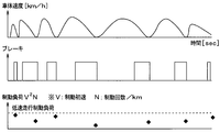
- 4 is a time chart showing a relationship between a brake operation, a vehicle speed, a calculation timing of a braking load, and the like.
- FIG. 1 is a schematic diagram showing an overall outline of a vehicle brake system to which an EPB control device including a brake temperature detection device according to the present embodiment is applied.
- an EPB control device including a brake temperature detection device according to the present embodiment is applied.
- the brake system includes a service brake 1 that generates a braking force based on a driver's pedaling force, and an EPB 2 that locks the wheel during parking to restrict the movement of the vehicle.
- the service brake 1 boosts the pedaling force according to the depression of the brake pedal 3 by the driver with the booster 4 and then generates a brake fluid pressure according to the boosted pedaling force in the M / C 5.
- Brake force is generated by transmitting the hydraulic pressure to each wheel cylinder (hereinafter referred to as W / C) 6 provided in the brake mechanism of each wheel.
- W / C wheel cylinder
- an actuator 7 for adjusting the brake fluid pressure is provided between the M / C 5 and the W / C 6 to adjust the brake force generated by the service brake 1 and improve the safety of the vehicle. Therefore, it is structured such that various types of control (for example, ABS control) can be performed.
- Various controls using the actuator 7 are executed by an ESC (Electronic Stability Control) -ECU 8.
- the brake fluid pressure circuit provided in the actuator 7 is controlled by outputting control currents for controlling various control valves provided in the actuator 7 and motors for driving the pump from the ESC-ECU 8, and the W / C Control the pressure.
- the actuator 7 transmits the M / C pressure generated in the M / C 5 to the W / C 6 as it is.
- the actuator 7 controls on / off of various control valves and drives the pump. By controlling this motor, the W / C pressure is increased or decreased so that wheel lock can be avoided.
- the actuator 7 can automatically increase the W / C pressure by driving various control valves and a pump driving motor.
- the M / C pressure is not generated or when the M / C pressure is higher than the M / C pressure, When it is desired to generate the C pressure, a high braking force can be generated based on the automatic pressurizing function.
- the structure of the actuator 7 has been well known in the art and will not be described in detail. However, the actuator 7 has a configuration including various control valves, a pump, a pump driving motor, and the like.
- the EPB 2 is controlled by an EPB control device (hereinafter referred to as an EPB-ECU) 9, and the EPB-ECU 9 drives the motor 10 to control the brake mechanism to generate a braking force.
- an EPB control device hereinafter referred to as an EPB-ECU
- the EPB-ECU 9 is constituted by a well-known microcomputer having a CPU, ROM, RAM, I / O, etc., and controls the rotation of the motor 10 according to a program stored in the ROM or the like, thereby performing lock control, release control, etc. Car parking brake control and fade warning processing.
- the lock control the driving force of the brake pad 11 against the brake disc 12 is generated by driving the motor 10 to generate a braking force by the EPB2, and when the braking force reaches the target braking force, the driving of the motor 10 is performed. Stop, hold the braking force and lock.
- the release control by driving the motor 10 in the opposite direction to the lock control, the pressing force applied to the brake pad 11 against the brake disc 12 is released, and the brake pad 11 and the brake disc 12 are separated by a predetermined distance. After that, the driving of the motor 10 is stopped and brought into a released state. Further, in the fade warning process, the brake temperature is detected, it is determined whether or not a fade state is established based on the brake temperature, and if the fade state is reached, a fade warning is performed. A portion of the EPB-ECU 9 that detects the brake temperature in the fade warning process constitutes the brake temperature detection device of the present invention.
- the EPB-ECU 9 and the ESC-ECU 8 exchange information with each other through CAN communication, which is an in-vehicle LAN.
- the EPB-ECU 9 obtains vehicle speed information handled by the ESC-ECU 8, STP information that is information on the state of a stop lamp switch (hereinafter referred to as STP), M / C pressure information, and the like. Have acquired. Since the ESC-ECU 8 obtains detection signals from a wheel speed sensor, STP and M / C pressure sensor (not shown), and obtains vehicle body speed information, STP information, and M / C pressure information based on these signals. Each information is transmitted to the EPB-ECU 9 through CAN communication.
- the EPB-ECU 9 receives, for example, a signal corresponding to the operation state of an operation switch (SW) 20 provided in an instrument panel (not shown) in the vehicle compartment and a detection signal of the acceleration sensor 21 in the vehicle longitudinal direction. Then, the motor 10 is driven based on the operation state of the operation SW 20 and the longitudinal acceleration of the vehicle. Further, the EPB-ECU 9 outputs a signal indicating whether it is locked or released to the lock / release indicator lamp 23 provided on the instrument panel, or when a failure of the EPB 2 is detected. Alternatively, at the time of a fade warning, a signal indicating that is output to the display device 24.
- SW operation switch
- the EPB-ECU 9 receives, for example, a signal corresponding to the operation state of an operation switch (SW) 20 provided in an instrument panel (not shown) in the vehicle compartment and a detection signal of the acceleration sensor 21 in the vehicle longitudinal direction. Then, the motor 10 is driven based on the operation state of the operation SW 20 and the longitudinal acceleration of the vehicle
- the EPB-ECU 9 detects the current (motor current) flowing to the motor 10 on the upstream side or downstream side of the motor 10 and the target motor current (target current value when the lock control is terminated). ) To calculate the target motor current, to determine whether or not the motor current has reached the target motor current, and to control the EPB2 based on the operation state of the operation SW 20, etc. ing.
- the EPB-ECU 9 controls the EPB 2 by rotating the motor 10 forward or backward or stopping the rotation of the motor 10 based on the state of the operation SW 20 or the motor current.
- the brake mechanism provided in each wheel has a mechanical structure that generates a braking force in the brake system of the present embodiment, and the brake mechanism of the front wheel system has a structure that generates a braking force by operating the service brake 1.
- the brake mechanism of the rear wheel system has a common structure that generates a braking force for both the operation of the service brake 1 and the operation of the EPB 2.
- the front-wheel brake mechanism is a brake mechanism that is generally used from the past, in which a mechanism that generates a braking force based on the operation of the EPB 2 is eliminated from the rear-wheel brake mechanism.
- the brake mechanism that generates braking force by operating the front wheel service brake 1 is conventionally used, and generates braking force in response to the operation of the rear wheel service brake 1 and EPB 2.
- the brake mechanism to be used is also known in, for example, Japanese Patent Application Laid-Open No. 2010-58536. For this reason, description of a detailed structure is abbreviate
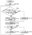
- FIG. 2 is a flowchart showing details of the fade warning process based on the brake temperature detection result. This process is executed at predetermined control cycles when, for example, an ignition switch (hereinafter referred to as IG) is turned on and the EPB-ECU 9 is activated.
- IG an ignition switch
- the brake temperature detection As the brake temperature detection, the brake temperature is detected by calculating the brake temperature increase amount and the brake temperature after cooling, and a fade warning is performed based on this. Further, since the brake temperature is detected in the fade warning process, the pressing force for pressing the brake disc 12 with the brake pad 11 during the lock control is determined using the result of the brake temperature detection.
- the amount of increase in the temperature of the brake represents the amount of increase in the temperature of the brake mechanism, more specifically, the brake pad 11 for each control cycle.
- the brake temperature after cooling represents the temperature of the brake mechanism after cooling in each control cycle, more specifically, the temperature of the brake pad 11. Therefore, a value obtained by adding the brake temperature increase amount to the brake temperature after cooling represents the brake temperature.
- step 100 normal initialization processing such as flag reset and memory value reset is performed, and then the routine proceeds to step 105 where braking determination is performed.
- brake determination it is determined whether or not the brake is being performed.
- (1) and (2) may be determined, or determination of whether or not the STP is normal or determination of whether or not the M / C pressure is effective is not performed. However, each determination is performed in order to provide redundancy.
- step 110 the brake temperature increase amount during braking is calculated by executing a brake temperature increase amount calculation process during braking.
- the amount of increase in brake temperature can be calculated by a well-known method. For example, the amount of increase in brake temperature based on kinetic energy or the amount of increase in brake temperature based on braking energy is calculated and used in combination. The amount of increase in brake temperature can be set.
- the amount of increase in brake temperature based on kinetic energy is the amount of heat that is expected to be generated in the brake when the kinetic energy generated in the vehicle is changed to braking force.
- the relationship between the kinetic energy generated in the vehicle and the amount of heat assumed when it is converted into braking force is determined in advance, and the brake based on the kinetic energy is converted by converting the kinetic energy of the vehicle into the amount of heat.
- the amount of temperature rise is obtained. Since the kinetic energy generated in the vehicle is expressed as 1/2 ⁇ mv2 when the vehicle weight is m and the vehicle body speed is v, the EPB-ECU 9 can acquire the vehicle speed information from the ESC-ECU 8 to obtain the motion. The energy is obtained, and the brake temperature increase corresponding to this kinetic energy is derived using the relationship obtained in advance.
- the amount of increase in the brake temperature based on the braking energy is achieved by pressing the amount of heat assumed from the energy when braking the vehicle, that is, by pressing the brake pad 11 that is a friction material against the brake disc 12 that is a friction material. This is the amount of increase in heat converted from work. For example, the relationship between the energy consumed by the braking force when braking the vehicle and the amount of heat assumed from the energy is obtained in advance, and the braking temperature rises based on the braking energy by converting the braking energy of the vehicle into the amount of heat. Seeking the amount.
- the braking energy is a value obtained by multiplying the W / C pressure, that is, the pressing force pressing the brake pad 11 against the brake disk 12, and the wheel rotation speed during braking, that is, the braking distance
- the EPB-ECU 9 The braking energy is obtained from the vehicle speed information and the M / C pressure information from the ESC-ECU 8, and the brake temperature increase corresponding to the braking energy is derived using the relationship obtained in advance.
- the brake temperature increase amount based on the braking energy is a value calculated based on the braking distance and the W / C pressure, and the friction coefficient between the brake pad 11 and the brake disk 12 included in the calculation formula. This is because it is easy to change depending on the environment (for example, ambient temperature and humidity).
- the brake temperature increase amount based on the kinetic energy is more accurate than the brake temperature increase amount based on the braking energy, so it is preferable to use the brake temperature increase amount based on the kinetic energy
- On the slope an error occurs in the kinetic energy calculation temperature rise due to the influence of gravity acceleration according to the slope of the slope.
- a more accurate brake temperature increase amount can be obtained by using the brake temperature increase amount based on the braking energy instead of the brake temperature increase amount based on the kinetic energy.
- the slope is determined by a well-known method based on the vehicle body acceleration, which is a differential value of the vehicle speed, or the detection signal of the acceleration sensor 21, any brake temperature increase amount is determined based on the determined slope. You can decide whether to use it.
- step 105 determines whether a negative determination is made in step 105 or not. If a negative determination is made in step 105, the process proceeds to step 115 and the brake cooling temperature is calculated by executing the cooling temperature calculation process.
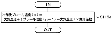
- FIG. 3 is a flowchart showing details of the cooling temperature calculation process.
- step 115a the control of this time is performed by adding the value obtained by multiplying the difference between the brake temperature (n-1) and the air temperature in the previous control cycle by the cooling coefficient to the air temperature.
- the brake temperature (n) after cooling in the cycle is calculated. That is, when braking is not being performed, brake friction does not occur between the brake pad 11 and the brake disc 12, so that brake cooling is performed.
- the temperature drop due to cooling is calculated based on Newton's law of cooling that the cooling rate is proportional to the difference between the brake temperature and the brake ambient temperature. Therefore, based on the equation shown in step 115a, The brake temperature after cooling (n) in the control cycle is calculated.
- the atmospheric temperature correction calculation process is executed, and the cooling temperature calculation process is executed based on the atmospheric temperature corrected by the atmospheric temperature correction calculation process.
- FIG. 4 is a flowchart showing details of the atmospheric temperature correction calculation process.
- the atmospheric temperature correction calculation processing may be incorporated in the flowchart shown in FIG. 2, but in the case of the present embodiment, it is executed as a separate flow.
- the corrected atmospheric temperature is input by a timer interrupt, and cooling is performed. It is used for calculating the brake cooling temperature in the temperature calculation process.
- the details of the atmospheric temperature correction calculation process will be described.
- the atmospheric temperature used for calculating the brake cooling temperature in the cooling temperature calculation process is corrected by correcting the atmospheric temperature indicated by the reading value of the detection signal of the temperature sensor 22 provided in the vehicle. Set to a value close to.
- a traffic jam determination process for determining that the vehicle is traveling in a traffic jam is executed. It is assumed that the brake ambient temperature rises when the vehicle is traveling in a traffic jam. Therefore, the atmospheric temperature is corrected when it is determined that the vehicle is traveling in a traffic jam.
- the temperature around the brake is higher than the atmospheric temperature indicated by the reading value of the detection signal of the temperature sensor 22, the vehicle is traveling in a traffic jam. If it matches the determination condition in the determination process, it corresponds to a situation in which the brake peripheral temperature rises even in other driving states, for example, when driving at low speed.
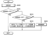
- FIG. 5 is a flowchart showing details of the traffic jam determination process.
- the traffic jam determination process first, as shown in step 200a of FIG. 5, it is determined whether the traffic jam determination is OFF, for example, whether a flag indicating the traffic jam determination result is in a reset state. If it is determined that the traffic jam is determined to be ON in the previous traffic jam determination process, the traffic jam determination is OFF. If this traffic jam determination is OFF, the process proceeds to step 200b to determine whether or not the traffic jam is present.
- the low-speed driving determination threshold and the low-speed driving determination time are thresholds used for determining the low-speed driving of the vehicle.
- the low-speed driving determination threshold is a speed threshold to be compared with the vehicle speed
- the low-speed driving determination time is a vehicle speed that is equal to or lower than the low-speed driving determination threshold.
- the low-speed traveling determination threshold and the low-speed traveling determination time mentioned here do not have to be one, and a plurality may be set.
- the relationship between the low-speed traveling determination threshold value and the low-speed traveling determination time may be indicated by a map or the like, and when the condition indicated in the relationship is satisfied, it may be determined that the vehicle is traveling in a traffic jam.
- the braking load means a load applied to the brake mechanism by braking, and is expressed as V2N, where V is the initial braking speed, which is the vehicle body speed at the start of braking, and N is the number of brakings per predetermined distance (for example, 1 km). Is done. For this reason, the higher the vehicle body speed and the greater the number of times of braking, the greater the braking load.
- the low-speed traveling braking load means a braking load that is assumed to be applied while the vehicle is traveling at a low speed. In the present embodiment, the low-speed traveling braking load is used as a threshold value for determining that the vehicle is traveling at a low speed.
- the low-speed traveling braking load count is a threshold value for determining that the vehicle is traveling at low speed due to traffic jams.
- the calculated braking load is continuously below the low-speed traveling braking load, the vehicle is traveling in traffic jams. This is the number of times to determine that there is.
- the low-speed traveling braking load and the number of low-speed traveling braking loads mentioned here do not have to be one, and a plurality of them may be set.
- the relationship between the low-speed traveling braking load and the number of low-speed traveling braking loads may be indicated by a map or the like, and it may be determined that the vehicle is traveling in a traffic jam when the condition indicated by the relationship is satisfied.
- step 200b If an affirmative determination is made in step 200b, the process proceeds to step 200c, where the congestion determination is turned ON, a congestion level indicating the degree of the congestion is obtained, and an atmospheric temperature correction value and a brake temperature correction value are set according to the congestion level. To do. Thereby, the atmospheric temperature correction value and the brake temperature correction value can be set according to the traffic congestion level, that is, the degree of temperature rise in the wheel house.
- the atmospheric temperature correction value is a temperature correction value used for correcting the atmospheric temperature read from the detection signal of the temperature sensor 22, and in view of the large divergence between the atmospheric temperature and the brake ambient temperature depending on the traffic congestion level, The greater the congestion level, the greater the value.
- the air temperature correction value may be a fixed value corresponding to the traffic level determined when it is determined that the vehicle is traveling in a traffic jam, but the degree of deviation between the air temperature and the brake ambient temperature continues to change after the determination. Therefore, it is preferable to use a variable value that is appropriately changed according to a change in the traffic congestion level after the determination.
- the brake temperature correction value corresponds to the amount of increase in brake temperature until the determination result that the vehicle is traveling in a traffic jam is obtained.
- This brake temperature correction value is also set to a larger value as the traffic congestion level increases, as with the above-described atmospheric temperature correction value. Even when it is determined that the vehicle is running in traffic jams, there is a discrepancy between the ambient temperature and the brake ambient temperature.
- the brake temperature correction value is obtained in order to cancel quickly.
- the brake temperature correction value is a correction value that is used only at the timing when the determination result that the vehicle is traveling in a traffic jam is issued. Therefore, even if the traffic jam level changes after the correction, the brake temperature correction value is not used.
- the relationship between the low-speed driving determination threshold value and the low-speed driving determination time and the relationship between the low-speed driving braking load and the number of low-speed driving braking loads are mapped, and the congestion level is set in the map. Then, the corresponding traffic congestion level can be selected from the map, and the atmospheric temperature correction value and the brake temperature correction value corresponding to the traffic congestion level can be obtained.
- FIG. 8 is a map showing an example of the relationship between the low-speed driving determination threshold value and the low-speed driving determination time and the traffic congestion level.
- the low-speed driving determination threshold is set in a plurality of stages, and the low-speed driving determination time is set in a plurality of stages for each threshold.
- the traffic congestion level can be set by selecting one corresponding to the map. For example, the lower the vehicle body speed, the more the brake peripheral temperature increases. Therefore, the smaller the low-speed traveling determination threshold value, the greater the congestion level even if the low-speed traveling determination time is shorter. Further, the congestion level is set to a larger value as the low-speed traveling determination time becomes longer. In other words, it is determined that the congestion level is higher as the vehicle body speed is lower than the lower value in the low-speed driving determination threshold or as the duration is longer than the low-speed driving determination time. Can do.
- FIG. 9 is a map showing an example of the relationship between the low-speed traveling braking load, the number of low-speed traveling braking loads, and the traffic congestion level.
- the low-speed traveling braking load is set in a plurality of stages, and the number of low-speed traveling braking loads is set in a plurality of stages for each load.
- the traffic congestion level can be set by selecting one corresponding to the map. For example, the lower the braking load is, the lower the vehicle is traveling at a low speed, and the higher the brake ambient temperature is. Therefore, the lower the low-speed traveling braking load, the greater the congestion level even if the number of low-speed traveling braking loads is small. Yes.
- the traffic congestion level is set to a larger value as the number of times of low-speed traveling braking is increased. That is, it can be determined that the congestion level is higher as the braking load is lower than the lower value in the low-speed traveling braking load or as the braking load is more than the lower number in the low-speed traveling braking load. .
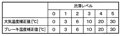
- FIG. 10 is a map showing the relationship between the congestion level, the atmospheric temperature correction value, and the brake temperature correction value. As shown in this figure, the air temperature correction value and the brake temperature correction value can be increased as the traffic congestion level increases.
- the relationship between the low-speed traveling determination threshold value and the low-speed traveling determination time and the relationship between the low-speed traveling braking load and the number of low-speed traveling braking loads are mapped, and based on the map, it is determined that the vehicle is traveling in a traffic jam.
- the map shown in FIGS. 8 and 9 may be used to determine that the vehicle is traveling in a traffic jam when the traffic jam level is 1 or higher.
- step 200b in FIG. 5 it is determined whether the vehicle is not traveling in a traffic jam or whether the vehicle is traveling in a traffic jam.
- the routine proceeds to step 200d, and the continuation time during which the vehicle body speed in the current control cycle is equal to or lower than the low speed traveling determination threshold and the number of times that the braking load is equal to or lower than the low speed traveling braking load are maintained as the previous value. To do.
- step 200b when calculating the duration time during which the vehicle body speed is less than or equal to the low-speed traveling determination threshold in step 200b and the number of times the braking load is less than or equal to the low-speed traveling braking load, hold here. The calculation is performed using the previous value.
- step 200e it is determined whether or not the vehicle body speed is equal to or higher than the high-speed driving determination threshold value.
- the high speed traveling determination threshold is a threshold for determining that the vehicle has finished traveling in a traffic jam and has shifted to high speed traveling.
- the air flow around the brake increases as the vehicle travels, and the difference between the brake ambient temperature and the air temperature indicated by the reading value of the detection signal of the temperature sensor 22 is reduced. For this reason, when the vehicle body speed is equal to or higher than the high speed determination threshold, it is determined that the vehicle has escaped the traffic jam.
- step 200f the congestion determination is turned off and the process is terminated.
- step 200g the previous value is held, that is, if the congestion determination is in an ON state in the previous control cycle, the state is maintained, and if it is in an OFF state, the state is maintained. Is held and the process ends. In this way, the congestion determination calculation process is terminated.
- step 205 in FIG. 4 determines whether the traffic congestion determination is OFF. If an affirmative determination is made here, it means that the vehicle is not traveling in a traffic jam, is in a state before it is determined that the vehicle is traveling in a traffic jam, or is a case where the traffic jam is canceled, and thus the atmospheric temperature correction calculation process is terminated. In this case, the atmospheric temperature indicated by the reading value of the detection signal of the temperature sensor 22 is used as it is as the brake ambient temperature.
- step 205 If a negative determination is made in step 205, the process proceeds to step 210, and it is determined whether or not it is the timing when the traffic jam determination is switched from OFF to ON. At this time, an affirmative determination is made in step 210 if it is the timing at which the congestion determination is switched ON in step 200c of FIG. 5 described above, and a negative determination is made if the timing is other than that.
- step 215. the atmospheric temperature correction value acquired in step 200c in FIG. 5 is added to the atmospheric temperature indicated by the reading value of the detection signal of the temperature sensor 22, and the atmospheric temperature is corrected to an ambient temperature close to the brake ambient temperature in consideration of the temperature increase due to the traffic running.
- this atmospheric temperature is referred to as the corrected atmospheric temperature.
- the smaller one of the brake temperature (n ⁇ 1) obtained in the previous control cycle and the corrected atmospheric temperature is set as the final atmospheric temperature.
- the corrected atmospheric temperature may be used as it is as the atmospheric temperature representing the final brake ambient temperature.
- Temperature (n-1) is set.
- step 210 the process proceeds to step 220.
- the atmospheric temperature set in the previous control cycle that is, the atmospheric temperature set in step 215 is held as it is. In this way, the atmospheric temperature correction calculation process ends.
- the cooling temperature calculation process in step 115 of FIG. 2 described above is performed using the atmospheric temperature set in consideration of the temperature rise during the traffic jam.
- FIG. 11 is a flowchart showing details of the brake temperature calculation process. As shown in this figure, in step 120a, it is determined whether or not it is the timing when the traffic jam determination is switched from OFF to ON. Also here, if the congestion determination is switched to ON in step 200c of FIG. 5 described above, an affirmative determination is made, and if it is any other timing, a negative determination is made.
- step 120b first, by adding the brake temperature correction value acquired in step 200c of FIG. 5 to the brake temperature after cooling obtained in the cooling temperature calculation process, it is determined that the vehicle is traveling in the traffic jam in the traffic jam determination process.
- a post-cooling brake temperature is calculated after correcting for the deviation between the ambient temperature and the brake ambient temperature.
- the smaller of the wheel house temperature upper limit value which is the upper limit value assumed when the temperature in the wheel house rises, and the corrected brake temperature after cooling is set as the final atmospheric temperature.
- the post-cooling brake temperature after correction may be used as the final post-cooling brake temperature, but the corrected atmospheric temperature does not become larger than the wheel house temperature upper limit value. Set to value. Then, it progresses to step 120c.
- step 120a If a negative determination is made in step 120a, the process proceeds to step 120c without proceeding to step 120b. It is not necessary to correct the brake temperature after cooling when the congestion determination is OFF, and even when the congestion determination is ON, the brake temperature after cooling is corrected once when the congestion determination is switched from OFF to ON. This is because it is not necessary to perform correction in the same manner.
- step 120c the brake temperature is calculated by adding the brake temperature increase during braking calculated in step 110 and the brake temperature after cooling calculated in step 115 (or step 120b). In this way, the brake temperature calculation process ends.
- step 125 it is determined whether or not the brake temperature has exceeded a fade temperature that is a threshold value for fade determination. If not, the process proceeds to step 135 to cancel the fade warning. In this way, the fade warning process is completed.
- FIG. 12 and FIG. 13 are time charts for the case where the atmospheric temperature correction calculation as executed in the fade warning process is not executed and the case where it is executed during a traffic jam.
- the brake temperature obtained by calculation (hereinafter referred to as brake calculation temperature) is basically the actual brake temperature (hereinafter referred to as brake actual temperature). It is close to the value.
- brake calculation temperature the brake temperature obtained by calculation
- brake actual temperature the actual brake temperature
- the brake calculation temperature deviates from the brake actual temperature until the determination as to whether or not the vehicle is traveling in a traffic jam is completed.
- the brake calculation temperature is calculated by adding the brake temperature correction value at that timing, and the air temperature is corrected. It becomes possible to make the temperature substantially coincide with the actual brake temperature. For this reason, it is determined whether or not a fade warning should be performed based on a brake calculation temperature substantially equal to the actual brake temperature, and it becomes possible to perform the fade warning more accurately.
- the fade warning process a situation in which the brake peripheral temperature rises higher than the atmospheric temperature indicated by the reading value of the detection signal of the temperature sensor 22, for example, the atmospheric temperature correction value when the vehicle is traveling in a traffic jam. And the atmospheric temperature is corrected based on the atmospheric temperature correction value. Then, the brake temperature is calculated based on the corrected atmospheric temperature. This makes it possible to bring the brake calculation temperature closer to the actual brake temperature. Therefore, it becomes possible to perform a fade warning more accurately.
- the EPB 2 can be locked based on the brake temperature calculated in this way. That is, when the EPB 2 is operated, if the brake temperature is high, the brake pad 11 is thermally contracted by the subsequent cooling, and a thermal loosening phenomenon occurs in which the braking force generated by the EPB 2 is reduced.
- the lock control end timing and the number of times of control based on the calculated brake temperature specifically, the stop timing of the motor 10 and the time from the end of the first lock control to the time of re-locking. You can set the time and the number of relocks.
- the current flowing through the motor 10 has a value corresponding to the load applied to the motor 10, and the load applied to the motor 10 is applied to the brake disk 12 by the brake pad 11.
- the value corresponds to the pressing force.
- the motor current is detected and the motor current becomes the target motor current, it is determined that the pressing force of the brake pad 11 to the brake disc 12 becomes a desired value, and the braking force by the EPB 2 reaches the target braking force.
- the driving of the motor 10 is stopped. Thereby, the state which generated desired braking force by EPB2 is maintained also at the time of parking.
- the target motor current at this time is calculated by calculating the target motor current, and the target motor current may be calculated in consideration of the brake temperature when calculating the target motor current. For example, if a coefficient term corresponding to the brake temperature is set and the target motor current is set to a larger value as the brake temperature is higher, parking can be maintained even if the brake pad 11 is lowered during parking. The desired braking force can be generated.
- a desired braking force can be generated by calculating the time until the relock control is performed by the EPB 2 and the number of times of the relock control. Since the degree of thermal looseness varies depending on the brake temperature when the first lock control is performed during parking, the time until the re-lock control and the re-lock control time depend on the brake temperature when the first lock control is performed. What is necessary is just to calculate the number of times. For example, when the brake temperature when the first lock control at the time of parking is performed is high, the difference between the brake temperature and the atmospheric temperature is large, so that the brake temperature is rapidly cooled and the degree of the thermal loosening phenomenon is also increased.
- the relock control is performed after a shorter time, and when the time further elapses, the relock control is performed again to generate a desired braking force. Can do. Further, when the brake temperature when the first lock control is performed is low, a desired braking force can be generated by maintaining the parking state by performing the re-lock control after a longer time has elapsed.
- the target motor current at the time of lock control is calculated based on the brake temperature, and the end timing of the lock control is determined based on the target motor current, or the brake temperature
- the disc brake type EPB 2 in which the friction material is the brake pad 11 and the friction material is the brake disc 12 is described as an example.
- other types such as a drum brake type may be used. Absent. In that case, the friction material and the friction material are a brake shoe and a drum, respectively.
- the steps shown in each figure correspond to means for executing various processes. That is, the part that executes the process of step 110 corresponds to the brake temperature increase calculating means, the part that executes the process of step 115 corresponds to the cooling temperature calculating means, and the part that executes the process of step 120 corresponds to the brake temperature calculating means. Further, the part that executes the process of step 200 comes to the temperature rise determination means, and the part that executes the process of step 200c comes to the traffic level determination means.
Landscapes
- Engineering & Computer Science (AREA)
- Transportation (AREA)
- Mechanical Engineering (AREA)
- Physics & Mathematics (AREA)
- General Physics & Mathematics (AREA)
- Regulating Braking Force (AREA)
- Valves And Accessory Devices For Braking Systems (AREA)
- Braking Systems And Boosters (AREA)
Abstract
Description
本発明の第1実施形態について説明する。本実施形態では、後輪系にディスクブレーキタイプのEPBを適用している車両用ブレーキシステムを例に挙げて説明する。図1は、本実施形態にかかるブレーキ温度検出装置を含むEPB制御装置が適用された車両用ブレーキシステムの全体概要を示した模式図である。以下、この図を参照して説明する。
本発明は上記した実施形態に限定されるものではなく、特許請求の範囲に記載した範囲内において適宜変更が可能である。
Claims (7)
- 制御周期ごとにブレーキ温度の検出を行うブレーキ温度検出装置であって、
制動時に、車両を制動させることによる前記ブレーキ温度の上昇量であるブレーキ温度上昇量を演算する制動時ブレーキ温度上昇量演算手段と、
前記制動時ではないときに、前記車両に備えられた温度センサの検出信号の読み取り値が示す大気温度と前回の制御周期の際に検出されたブレーキ温度との差に基づいて、自然冷却によって冷却されたブレーキ温度である冷却後ブレーキ温度を演算する冷却温度演算手段と、
前記ブレーキ温度上昇量と前記冷却後ブレーキ温度とを足すことで、今回の制御周期におけるブレーキ温度を検出するブレーキ温度演算手段と、
前記温度センサの検出信号の読み取り値が示す大気温度よりも前記車両におけるホイールハウス内の温度が高くなる状況を判定する温度上昇判定手段を備え、
前記冷却温度演算手段は、該温度上昇判定手段にて前記ホイールハウス内の温度が高くなる状況であると判定されると、前記温度センサの検出信号の読み取り値が示す大気温度に対して大気温度補正値を足すことで前記大気温度を補正し、補正後の前記大気温度を用いて前記冷却後ブレーキ温度を演算することを特徴とするブレーキ温度検出装置。 - 前記冷却温度演算手段は、前記温度上昇判定手段にて前記ホイールハウス内の温度が高くなる状況であると判定されたときに、前記冷却後ブレーキ温度に対してブレーキ温度補正値を足すことで前記冷却後ブレーキ温度を補正し、
前記ブレーキ温度演算手段では、補正後の前記冷却後ブレーキ温度を用いて前記ブレーキ温度を検出することを特徴とする請求項1に記載のブレーキ温度検出装置。 - 前記温度上昇判定手段は、前記車両が渋滞走行中のときに前記ホイールハウス内の温度が高くなる状況と判定し、前記温度センサの検出信号の読み取り値が示す大気温度よりも高い値に前記大気温度を補正することを特徴とする請求項2に記載のブレーキ温度検出装置。
- 渋滞の度合いを示す渋滞レベルを判定する渋滞レベル判定手段を有し、
前記渋滞レベルが高いほど、前記大気温度補正値および/または前記ブレーキ温度補正値を大きな値に設定することを特徴とする請求項2または3に記載のブレーキ温度検出装置。 - 前記渋滞レベル判定手段は、前記車両の車体速度と比較される閾値として複数段階設定された低速走行判定閾値と、前記車体速度が前記低速走行判定閾値以下となっている継続時間と比較される閾値として複数段階設定された低速走行判定時間とを有し、前記車体速度が前記低速走行判定閾値の中でもより低い値以下となっているほど、もしくは、前記継続時間が前記低速走行判定時間の中でもより長い時間以上になっているほど、前記渋滞レベルが高いと判定することを特徴とする請求項4に記載のブレーキ温度検出装置。
- 前記渋滞レベル判定手段は、制動開始時の前記車体速度である制動初速と所定距離当たりの制動回数とによって示される制動負荷と比較される閾値として複数段階設定された低速走行制動負荷と、前記制動負荷が前記低速走行制動負荷以下となっている回数と比較される閾値として複数段階設定された低速走行制動負荷回数とを有し、前記制動負荷が前記低速走行制動負荷の中でもより低い値以下となっているほど、もしくは、前記制動負荷が前記低速走行制動負荷以下となっている回数が前記低速走行制動負荷回数の中でもより多い回数以上となっているほど、前記渋滞レベルが高いと判定することを特徴とする請求項4または5に記載のブレーキ温度検出装置。
- モータを駆動することによって前記摩擦材を前記被摩擦材に押圧する押圧力を発生させ、前記摩擦材と前記被摩擦材との摩擦によってブレーキ力を発生させる電動駐車ブレーキの制御を行う電動駐車ブレーキ制御装置であって、
前記モータを駆動することにより前記押圧力を発生させることで前記電動駐車ブレーキによるブレーキ力を発生させ、該ブレーキ力が目標制動力に達すると前記モータの駆動を停止し、前記ブレーキ力を保持してロック状態にさせるロック制御を行うロック制御手段を有し、
前記ロック制御手段は、請求項1ないし6のいずれか1つに記載のブレーキ温度検出装置にて検出されたブレーキ温度に基づいて、前記ロック制御の終了タイミングまたは前記ロック制御の制御回数を設定していることを特徴とする電動駐車ブレーキ制御装置。
Priority Applications (3)
| Application Number | Priority Date | Filing Date | Title |
|---|---|---|---|
| CN201480051746.3A CN105579310B (zh) | 2013-09-20 | 2014-09-19 | 制动器温度检测装置以及电动停车制动器控制装置 |
| US15/022,398 US9840241B2 (en) | 2013-09-20 | 2014-09-19 | Brake temperature detection device and electric parking brake control device |
| DE112014005892.0T DE112014005892T5 (de) | 2013-09-20 | 2014-09-19 | Bremsentemperaturerfassungsvorrichtung und Steuervorrichtung einer elektrischen Parkbremse |
Applications Claiming Priority (2)
| Application Number | Priority Date | Filing Date | Title |
|---|---|---|---|
| JP2013195485A JP5904182B2 (ja) | 2013-09-20 | 2013-09-20 | ブレーキ温度検出装置および電動駐車ブレーキ制御装置 |
| JP2013-195485 | 2013-09-20 |
Publications (1)
| Publication Number | Publication Date |
|---|---|
| WO2015041333A1 true WO2015041333A1 (ja) | 2015-03-26 |
Family
ID=52688980
Family Applications (1)
| Application Number | Title | Priority Date | Filing Date |
|---|---|---|---|
| PCT/JP2014/074892 Ceased WO2015041333A1 (ja) | 2013-09-20 | 2014-09-19 | ブレーキ温度検出装置および電動駐車ブレーキ制御装置 |
Country Status (5)
| Country | Link |
|---|---|
| US (1) | US9840241B2 (ja) |
| JP (1) | JP5904182B2 (ja) |
| CN (1) | CN105579310B (ja) |
| DE (1) | DE112014005892T5 (ja) |
| WO (1) | WO2015041333A1 (ja) |
Families Citing this family (12)
| Publication number | Priority date | Publication date | Assignee | Title |
|---|---|---|---|---|
| KR101682989B1 (ko) * | 2015-04-09 | 2016-12-06 | 주식회사 만도 | 차량의 전자식 주차 브레이크 시스템 및 그 제어 방법 |
| GB2549736A (en) | 2016-04-26 | 2017-11-01 | Airbus Operations Ltd | Predicting brake cooling periods |
| CN106314414A (zh) * | 2016-08-26 | 2017-01-11 | 蔡景洋 | 载货车辆及车辆制动系温度监测系统和方法 |
| CN107884081B (zh) * | 2016-09-30 | 2020-01-31 | 广东美的生活电器制造有限公司 | 温度显示方法及装置、液体加热容器 |
| CN110539737A (zh) * | 2018-05-28 | 2019-12-06 | 比亚迪股份有限公司 | 车辆驻车方法、装置、存储介质、电子设备及车辆 |
| AT522039B1 (de) * | 2018-12-17 | 2020-11-15 | Greenbrakes Gmbh | Bremsenanlage |
| KR102890415B1 (ko) * | 2020-12-14 | 2025-11-24 | 에이치엘만도 주식회사 | 전동 드럼 브레이크 시스템 및 그 제어방법 |
| JP7677051B2 (ja) * | 2021-08-05 | 2025-05-15 | 株式会社デンソー | 車両用制御装置及び車両用制御方法 |
| CN113799759A (zh) * | 2021-10-13 | 2021-12-17 | 北京福田戴姆勒汽车有限公司 | 制动辅助系统和具有其的车辆 |
| CN114312723A (zh) * | 2022-01-14 | 2022-04-12 | 中国第一汽车股份有限公司 | 制动盘温度确定方法、装置及车辆 |
| CN120056936B (zh) * | 2025-04-25 | 2025-08-26 | 福州职业技术学院 | 一种汽车制动冷却改进控制系统 |
| CN120588965B (zh) * | 2025-08-11 | 2025-10-10 | 南通职业大学 | 一种用于制动器温度监测的控制方法及系统 |
Citations (4)
| Publication number | Priority date | Publication date | Assignee | Title |
|---|---|---|---|---|
| JPH05116613A (ja) * | 1991-10-29 | 1993-05-14 | Mazda Motor Corp | 車両のスリツプ制御装置 |
| JP2001122107A (ja) * | 1999-10-22 | 2001-05-08 | Akebono Brake Ind Co Ltd | ブレーキのフェード警告発生装置 |
| JP2006298191A (ja) * | 2005-04-21 | 2006-11-02 | Nissan Motor Co Ltd | 駐車ブレーキ装置 |
| JP2009149256A (ja) * | 2007-12-21 | 2009-07-09 | Toyota Motor Corp | 駐車ブレーキ内蔵ディスクブレーキ |
Family Cites Families (10)
| Publication number | Priority date | Publication date | Assignee | Title |
|---|---|---|---|---|
| JPH04201712A (ja) * | 1990-11-30 | 1992-07-22 | Zexel Corp | 車両用空調装置 |
| JPH1191550A (ja) * | 1997-09-26 | 1999-04-06 | Mazda Motor Corp | 車両用警報装置 |
| JP2004175203A (ja) * | 2002-11-27 | 2004-06-24 | Advics:Kk | 電動パーキングブレーキ装置 |
| JP2005119343A (ja) * | 2003-10-14 | 2005-05-12 | Asmo Co Ltd | 電動駐車ブレーキ装置及びその制御方法 |
| JP4797934B2 (ja) * | 2006-01-19 | 2011-10-19 | 株式会社アドヴィックス | 車両用ディスクブレーキ制御装置 |
| CN101365893B (zh) * | 2006-02-08 | 2011-03-23 | 株式会社日立制作所 | 电动制动装置 |
| GB0802212D0 (en) * | 2008-02-06 | 2008-03-12 | Meritor Heavy Vehicle Braking | A brake system and method |
| JP4993416B2 (ja) * | 2008-03-24 | 2012-08-08 | スズキ株式会社 | エンジンの点火時期制御装置 |
| US8731795B2 (en) * | 2010-10-12 | 2014-05-20 | Bendix Commercial Vehicle Systems Llc | System and method for reducing brake fade |
| US8798846B2 (en) * | 2012-04-12 | 2014-08-05 | Toyota Motor Engineering & Manufacturing North America, Inc. | Power limiting system and method based upon brake rotor temperature determination |
-
2013
- 2013-09-20 JP JP2013195485A patent/JP5904182B2/ja active Active
-
2014
- 2014-09-19 US US15/022,398 patent/US9840241B2/en not_active Expired - Fee Related
- 2014-09-19 WO PCT/JP2014/074892 patent/WO2015041333A1/ja not_active Ceased
- 2014-09-19 DE DE112014005892.0T patent/DE112014005892T5/de not_active Withdrawn
- 2014-09-19 CN CN201480051746.3A patent/CN105579310B/zh not_active Expired - Fee Related
Patent Citations (4)
| Publication number | Priority date | Publication date | Assignee | Title |
|---|---|---|---|---|
| JPH05116613A (ja) * | 1991-10-29 | 1993-05-14 | Mazda Motor Corp | 車両のスリツプ制御装置 |
| JP2001122107A (ja) * | 1999-10-22 | 2001-05-08 | Akebono Brake Ind Co Ltd | ブレーキのフェード警告発生装置 |
| JP2006298191A (ja) * | 2005-04-21 | 2006-11-02 | Nissan Motor Co Ltd | 駐車ブレーキ装置 |
| JP2009149256A (ja) * | 2007-12-21 | 2009-07-09 | Toyota Motor Corp | 駐車ブレーキ内蔵ディスクブレーキ |
Also Published As
| Publication number | Publication date |
|---|---|
| CN105579310B (zh) | 2017-11-10 |
| US20160221550A1 (en) | 2016-08-04 |
| CN105579310A (zh) | 2016-05-11 |
| JP2015058889A (ja) | 2015-03-30 |
| JP5904182B2 (ja) | 2016-04-13 |
| US9840241B2 (en) | 2017-12-12 |
| DE112014005892T5 (de) | 2016-09-01 |
Similar Documents
| Publication | Publication Date | Title |
|---|---|---|
| JP5904182B2 (ja) | ブレーキ温度検出装置および電動駐車ブレーキ制御装置 | |
| JP5842877B2 (ja) | ブレーキ温度検出装置および電動駐車ブレーキ制御装置 | |
| JP5835576B2 (ja) | 車両の制動制御装置 | |
| JP5846070B2 (ja) | 電動駐車ブレーキ制御装置 | |
| JP4829289B2 (ja) | 車両の姿勢安定制御方法及びその装置 | |
| WO2007091337A1 (ja) | 電動ブレーキ装置 | |
| US20150314759A1 (en) | Vehicle movement dynamics control method | |
| JP6256456B2 (ja) | 車両の停止維持装置 | |
| JP2014118065A (ja) | 電子制御ブレーキシステム及びブレーキ制御方法 | |
| US8229665B2 (en) | Vehicle control apparatus for avoiding contact with obstacle locating backward | |
| JP2012240641A (ja) | 車両用ブレーキ制御装置 | |
| JP7159326B2 (ja) | モータサイクルの挙動を制御する制御装置及び制御方法 | |
| CN117302128A (zh) | 防抱死方法、车辆及存储介质 | |
| JPH1172129A (ja) | 車両におけるブレーキ摩擦材の温度推定方法 | |
| Kant | Sensotronic brake control (SBC) | |
| JP6191142B2 (ja) | 電動駐車ブレーキ制御装置 | |
| US12409818B2 (en) | Control device | |
| JP4328746B2 (ja) | ベンド走行中の減速車両用内側および外側ブレーキの管理方法および装置 | |
| KR20100040358A (ko) | 차량용 브레이크 디스크의 온도 추정방법 | |
| JP6447042B2 (ja) | 車両用ブレーキ装置 | |
| JP2020019376A (ja) | ブレーキ制御装置 | |
| JP6515950B2 (ja) | 車両制動制御装置 | |
| KR102162648B1 (ko) | 회생 제동 제어 방법 | |
| JPH09164930A (ja) | ブレーキ制御方法 | |
| JP2004284398A (ja) | 車両用ブレーキ装置 |
Legal Events
| Date | Code | Title | Description |
|---|---|---|---|
| WWE | Wipo information: entry into national phase |
Ref document number: 201480051746.3 Country of ref document: CN |
|
| 121 | Ep: the epo has been informed by wipo that ep was designated in this application |
Ref document number: 14845498 Country of ref document: EP Kind code of ref document: A1 |
|
| WWE | Wipo information: entry into national phase |
Ref document number: 15022398 Country of ref document: US |
|
| WWE | Wipo information: entry into national phase |
Ref document number: 112014005892 Country of ref document: DE |
|
| NENP | Non-entry into the national phase |
Ref country code: DE |
|
| 122 | Ep: pct application non-entry in european phase |
Ref document number: 14845498 Country of ref document: EP Kind code of ref document: A1 |