WO2015040786A1 - カラーおよびそのカラーを備える車両用のサンバイザ - Google Patents
カラーおよびそのカラーを備える車両用のサンバイザ Download PDFInfo
- Publication number
- WO2015040786A1 WO2015040786A1 PCT/JP2014/004270 JP2014004270W WO2015040786A1 WO 2015040786 A1 WO2015040786 A1 WO 2015040786A1 JP 2014004270 W JP2014004270 W JP 2014004270W WO 2015040786 A1 WO2015040786 A1 WO 2015040786A1
- Authority
- WO
- WIPO (PCT)
- Prior art keywords
- locking hole
- collar
- halves
- pair
- shaft
- Prior art date
- Legal status (The legal status is an assumption and is not a legal conclusion. Google has not performed a legal analysis and makes no representation as to the accuracy of the status listed.)
- Ceased
Links
Images


Classifications
-
- B—PERFORMING OPERATIONS; TRANSPORTING
- B60—VEHICLES IN GENERAL
- B60J—WINDOWS, WINDSCREENS, NON-FIXED ROOFS, DOORS, OR SIMILAR DEVICES FOR VEHICLES; REMOVABLE EXTERNAL PROTECTIVE COVERINGS SPECIALLY ADAPTED FOR VEHICLES
- B60J3/00—Antiglare equipment associated with windows or windscreens; Sun visors for vehicles
- B60J3/02—Antiglare equipment associated with windows or windscreens; Sun visors for vehicles adjustable in position
- B60J3/0204—Sun visors
- B60J3/0213—Sun visors characterised by the mounting means
- B60J3/0265—Attachments of sun visors to mounting means including details of sun visor bearing member regulating the rotational friction on the support arm
-
- B—PERFORMING OPERATIONS; TRANSPORTING
- B60—VEHICLES IN GENERAL
- B60J—WINDOWS, WINDSCREENS, NON-FIXED ROOFS, DOORS, OR SIMILAR DEVICES FOR VEHICLES; REMOVABLE EXTERNAL PROTECTIVE COVERINGS SPECIALLY ADAPTED FOR VEHICLES
- B60J3/00—Antiglare equipment associated with windows or windscreens; Sun visors for vehicles
- B60J3/02—Antiglare equipment associated with windows or windscreens; Sun visors for vehicles adjustable in position
- B60J3/0204—Sun visors
- B60J3/0213—Sun visors characterised by the mounting means
- B60J3/0265—Attachments of sun visors to mounting means including details of sun visor bearing member regulating the rotational friction on the support arm
- B60J3/0273—Attachments of sun visors to mounting means including details of sun visor bearing member regulating the rotational friction on the support arm on both end regions of sun visor
-
- B—PERFORMING OPERATIONS; TRANSPORTING
- B60—VEHICLES IN GENERAL
- B60J—WINDOWS, WINDSCREENS, NON-FIXED ROOFS, DOORS, OR SIMILAR DEVICES FOR VEHICLES; REMOVABLE EXTERNAL PROTECTIVE COVERINGS SPECIALLY ADAPTED FOR VEHICLES
- B60J3/00—Antiglare equipment associated with windows or windscreens; Sun visors for vehicles
- B60J3/02—Antiglare equipment associated with windows or windscreens; Sun visors for vehicles adjustable in position
- B60J3/0204—Sun visors
- B60J3/0213—Sun visors characterised by the mounting means
- B60J3/023—Additional support bracket releasably holding the sun visor
Definitions
- the present invention relates to a collar including a pair of halves and a sun visor for a vehicle including the collar.
- a sun visor is provided on the ceiling in front of the driver's and passenger's seats to protect the eyes of the driver from direct sunlight and ensure visibility.
- the sun visor is provided so that its position can be adjusted according to the position of the sun.
- a vehicle sun visor described in Patent Document 1 is a sun visor body, a shaft body that is attached to the sun visor body, supports the sun visor body, covers the shaft body, and is a cylinder that is hooked on a hook on the ceiling surface of the passenger compartment. And comprising.
- This cylindrical body is composed of two divided bodies that can be assembled from the outer peripheral side of the shaft body.
- One of the divided bodies is provided with an engaging claw that protrudes in the opposing direction and can be elastically deformed.
- a locking portion for locking the engaging claw is provided.
- the present invention has been made in view of such problems, and an object thereof is to provide a technique capable of suppressing the manufacturing cost of a collar formed by combining halves of the same shape.
- a collar according to an aspect of the present invention is a collar that is attached to a shaft body that supports a shield of a vehicle sun visor, and is a pair of halves that are attached so as to sandwich the outer periphery of the shaft body.
- a split body is provided.
- the half-divided body is formed on the inner surface of the half-divided body, and includes an accommodation groove for accommodating a part of the shaft, a locking hole formed so as to cut out the inner surface of the half-divided body, and the half-divided body And a flexure claw portion that is formed so as to stand up from the inner surface and has flexibility.
- the bending claw portion is bent and locked to the locking hole, and can be attached to the outer periphery of the shaft body with one touch. Since the pair of halves have the same shape, the manufacturing cost can be reduced. The user can easily confirm the mounting state by the operational feeling generated when the flexing claw is locked in the locking hole.
- the manufacturing cost can be reduced.
- FIG. 1A is a perspective view of the sun visor
- FIG. 1B is a partial perspective view of the sun visor focusing on the collar.
- 2 (a) is a perspective view of the collar
- FIG. 2 (b) is a perspective view of the outer side of the half body
- FIG. 2 (c) is a perspective view of the inner side of the half body.
- 3 (a) is a front view of the inside of the half body
- FIG. 3 (b) is a side view of the half body
- FIG. 3 (c) is a front view of the outside of the half body.
- FIG. 3 (d) is a side end view of the halved body.
- 4A is a side view of the collar
- FIG. 4B is a cross-sectional view of the line segment AA of the collar shown in FIG. 4A
- FIG. 3 is a cross-sectional view of a color line segment BB shown in FIG.
- FIG. 1A is a perspective view of the sun visor 10
- FIG. 1B is a partial perspective view of the sun visor 10 focusing on the collar 18.
- the sun visor 10 is fixed to the vehicle body panel on the ceiling of the driver's seat and the passenger seat of the vehicle, and is used for suppressing dazzling and dizziness caused by sunlight and oncoming vehicle lights.
- the sun visor 10 is rotatably connected to the vehicle body so that the position can be adjusted.
- the sun visor 10 includes a mounting portion 12, a shaft body 14, a shield body 16, and a collar 18.
- the attaching portion 12 attaches the sun visor 10 to the vehicle body so as to be rotatable.
- the shaft body 14 is inserted through the inside of the flat shield 16 and supports the shield 16.
- the shaft body 14 is continuous along the outer shape of the shielding body 16, and both ends thereof are connected to the mounting portion 12.
- the shaft body 14 is made of metal, and the shielding body 16 and the collar 18 are made of resin.
- the shield 16 is provided with a notch 16a that exposes a part of the shaft 14.
- a collar 18 is provided on the outer periphery of the shaft body 14 as shown in FIG.
- the collar 18 is locked by a locking portion (not shown) such as a hook provided on the vehicle body.
- the shield 16 can be rotated while the collar 18 is locked to the hook.
- the driver or the like adjusts the position of the sun visor 10
- the driver rotates the sun visor 10 with the collar 18 locked to the hook, while rotating the shield 16 by releasing the locking of the collar 18 to the hook. be able to.
- the sun visor 10 takes two states, a state in which the sun visor 10 is supported only by the attachment portion 12 and a state in which the collar 18 is locked to the hook in addition to the attachment portion 12, and the shield 16 can be moved in either state. it can.
- the collar 18 includes a pair of halves 20 that are attached so as to sandwich the outer periphery of the shaft body 14, and the halves 20 having the same shape are combined to form a cylindrical collar 18. Loads in various directions transmitted to the collar 18 include loads from the inside of the collar 18 received from the inner shaft body 14 as well as loads from the outside of the collar 18 received from a hook for locking the collar 18.
- the halved body 20 will be described in detail with reference to the component drawings. It should be noted that the same or equivalent components and members shown in the following drawings are denoted by the same reference numerals, and redundant description will be omitted as appropriate.
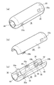
- FIG. 2A is a perspective view of the collar 18, FIG. 2B is a perspective view of the outer side of the half body 20, and FIG. 2C is a perspective view of the inner side of the half body 20.
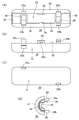
- FIG. 3 (a) is a front view of the inside of the half body 20
- FIG. 3 (b) is a side view of the half body 20
- FIG. 3 (c) is a side view of the half body 20.
- FIG. 3 (d) is a side end view of the halved body 20.
- the collar 18 is formed by combining a pair of halves 20 and an accommodation groove 38 for accommodating the shaft body 14 is formed on the inner surface.
- a housing space for the shaft body 14 is formed by each housing groove 38 of the half body 20. Since all of the halves 20 have the same shape, the collar 18 can be formed by combining halves having different shapes to form a single mold, and the manufacturing cost can be reduced.
- the halved body 20 includes a main body 21, a first locking hole 22a and a second locking hole 22b (referred to as a locking hole 22 if not distinguished), a first bending claw 24a and a second bending. It has a claw portion 24b (referred to as a bent claw portion 24 if not distinguished), a coupling portion 26, a coupled portion 28, a gripping portion 30, a mating surface 36, and a receiving groove 38.
- the outer peripheral surface of the main body 21 of the halved body 20 has a semi-cylindrical shape.
- a first locking hole 22a and a second locking hole 22b penetrate the outer peripheral surface of the main body 21 from the inside to the outside.
- the inner surface of the half body 20 is a surface located inside the cylindrical shape when the collar 18 is formed, and includes the grip portion 30, the mating surface 36, and the accommodation groove 38.
- a housing groove 38 extending along the central axis is formed on the inner surface of the half body 20, and a pair of mating surfaces 36 along the central axis are formed at the edges thereof.
- the mating surface 36 is formed at the edge of the inner surface of the half body 20 with the accommodation groove 38 interposed therebetween.
- the housing groove 38 secures a housing space for housing a part of the shaft body 14.
- the mating surface 36 is a plane that contacts when the pair of halves 20 are combined.
- the bending claw portion 24 is formed so as to stand up from the mating surface 36 and has flexibility.
- the bending claw portion 24 has a protruding portion 40 that protrudes in a direction that intersects the standing direction of the bending claw portion 24. Further, the protruding portion 40 protrudes radially outward with respect to the central axis of the half body 20.
- the locking hole 22 is formed so as to cut out the mating surface 36.
- a part of the locking hole portion 22 and the bending claw portion 24 may be formed from the mating surface 36 to the accommodation groove 38. Further, the locking hole portion 22 and the bending claw portion 24 may be formed in the receiving groove 38, and even in that case, the shaft body 14 is disposed between the locking hole portion 22 and the bending claw portion 24.
- the locking hole portion 22 and the bending claw portion 24 face each other so that the accommodation groove 38 is included therebetween.
- the locking hole portion 22 and the flexing claw portion 24 are formed in the mating surface 36 and / or the housing groove 38 which are the inner surfaces of the half body 20.
- the first locking hole portion 22a and the first bending claw portion 24a are opposed to each other with the accommodation groove 38 interposed therebetween, and the second locking hole portion 22b and the second bending claw portion 24b are arranged to face each other with the accommodation groove 38 interposed therebetween. Is done. Thereby, the locking hole part 22 and the bending nail
- the pair of locking hole portions 22 and the flexure claw portions 24 are respectively provided on both end sides in the axial direction of the half body 20.
- the pair of locking hole portions 22 and the flexure claw portions 24 have a relationship of facing each other with the accommodation groove 38 interposed therebetween.
- the term “both ends in the axial direction” is not limited to the end of the halved body 20, and includes a position slightly closer to the center than the end. Thereby, when the shaft body 14 is twisted, both ends of the collar 18 are fixed, so that the possibility that the locking hole portion 22 and the bending claw portion 24 are unlocked can be reduced. Moreover, it can suppress that the both ends of the half body 20 warp outward.
- the gripping portions 30 are respectively formed on both end portions in the axial direction of the half body 20 and grip the shaft body 14. As shown in FIG. 3D, the grip portion 30 has an inner peripheral surface having a smaller diameter than the accommodation groove 38.
- the inner diameter of the grip portion 30 is set according to the outer diameter of the shaft body 14 and is set slightly larger than the outer diameter of the shaft body 14.
- the grip portion 30 is provided on a line where the pair of bending claw portions 24 and the locking hole portion 22 face each other in the axial direction. That is, the grip portion 30 is formed so as to be stacked on the inner peripheral surface of the accommodation groove 38 between the opposing locking hole portion 22 and the flexing claw portion 24.
- the shaft body 14 is pressed by the grip portions 30 located on both sides in the axial direction, and the locking hole portion 22 and the flexing claw portion 24 are locked at the axial position, so that deformation of both ends of the collar 18 is suppressed. be able to. Since the grip portion 30 is provided on a line where the pair of flexure claw portions 24 and the locking hole portion 22 are opposed to each other, the collar 18 is locked in the vicinity of the grip portion 30 where the load from the shaft body 14 is applied, and the collar 18 is halved. It is possible to suppress separation into 20 opposing directions. There may not be the main body portion 21 on the outer side in the axial direction from the grip portion 30, and the grip portion 30 may be located at the end. In the attached state, the shaft body 14 slides on the inner peripheral surface of the grip portion 30.
- the coupling portion 26 protrudes from the mating surface 36 along the direction in which the bending claw portion 24 is inserted into the locking hole 22, and a concave portion 26 a is formed at a portion projecting from the mating surface 36.
- the coupled portion 28 is formed in a convex shape, and can be coupled by fitting into the concave portion 26a.
- the coupling portion 26 and the coupled portion 28 face each other with the accommodation groove 38 interposed therebetween.
- the concave portion 26a in the coupling portion 26 protruding from the half body 20, it is possible to avoid forming a recess in the inner surface of the housing groove 38 of the half body 20, and the rigidity of the main body portion 21 is reduced. And deformation of the main body 21 can be suppressed.
- the recessed part 26a is formed in the range of the plate
- bond part 26 is between the 1st locking hole part 22a and the 1st bending claw part 24a, and the 2nd locking hole part 22b and the 2nd bending claw part 24b, the inner surface of the half body 20 From the mating surface 36 and / or the receiving groove 38.
- a pair of coupling portions 26 and a coupled portion 28 that are opposed to each other with the accommodation groove 38 interposed therebetween are provided.
- the central portion can be prevented from being lifted by the coupling portion 26 and the coupled portion 28 while being firmly locked by the locking hole portion 22 and the bending claw portion 24 at both ends of the half body 20.
- the coupling portion 26 and the coupled portion 28 are provided so as not to grip the shaft body 14 when attached to the shaft body 14. Thereby, the influence of the distortion by the load from the shaft body 14 can be suppressed by making the central portion of the collar 18 non-contact with the shaft body 14.
- a large diameter portion 42 having a large inner diameter is formed on both ends.
- the large diameter portion 42 allows the cover of the shield 16 to enter the inside of the collar 18.
- FIG. 4A is a side view of the collar 18
- FIG. 4B is a cross-sectional view of the line segment AA of the collar 18 shown in FIG. 4A
- FIG. FIG. 5 is a cross-sectional view taken along line BB of the collar 18 shown in FIG.
- the protruding portion 40 of the bending claw portion 24 protrudes to the outer surface side along the mating surface 36 and protrudes in a direction intersecting the standing direction of the bending claw portion 24.
- the locking hole portion 22 also penetrates to the outer surface of the half body 20 in the direction intersecting the standing direction of the bending claw portion 24.
- the protruding portion 40 is provided so as to sandwich the edge of the locking hole portion 22 between the protruding portion 40 and the mating surface 36 with respect to the locking hole portion 22.
- the locking hole portion 22 is recessed in the facing direction of the mating surface 36, bent vertically in the middle or bent so as to intersect the facing direction in the middle, and passes through the mating surface 36 as it is.
- the bending claw 24 is locked to the locking hole 22 while being bent inward in the radial direction.
- the bending claw portion 24 is locked to the locking hole portion 22 in a biased state.
- claw part 24 can exhibit more resistance with respect to the position shift to the radial direction of the mating surface 36, and the position shift of the half body 20 can be suppressed.
- a convex coupled portion 28 is inserted into the concave portion 26a of the coupling portion 26 and coupled.
- the coupling portion 26 and the coupled portion 28 are located radially outward from the inner peripheral surface of the grip portion 30 when viewed from the axial direction. Thereby, the coupling
- FIG. The coupling portion 26 protrudes in the opposite direction of the half body 20 and functions as a guide when the pair of half bodies 20 are assembled.
- the coupling portion 26 and the coupled portion 28 are locked by concavity and convexity.
- a convex portion is formed on the inner wall surface of the coupling portion 26 and the inner circumferential surface of the opposing receiving groove 38 is covered. You may form the recessed part as the coupling
- Sun visor 12 mounting part, 14 shaft body, 16 shield, 18 collar, 20 half-divided body, 21 body part, 22 locking hole part, 22a first locking hole part, 22b second locking hole part, 24 Deflection claw part, 24a 1st deflection claw part, 24b 2nd deflection claw part, 26 coupling part, 26a concave part, 28 coupled part, 30 gripping part, 36 mating surface, 38 accommodating groove, 40 protruding part.
- the present invention relates to a collar including a pair of halves and a sun visor for a vehicle including the collar.
Landscapes
- Engineering & Computer Science (AREA)
- Mechanical Engineering (AREA)
- Snaps, Bayonet Connections, Set Pins, And Snap Rings (AREA)
- Clamps And Clips (AREA)
- Facsimile Scanning Arrangements (AREA)
- Fax Reproducing Arrangements (AREA)
- Facsimiles In General (AREA)
- Measuring Pulse, Heart Rate, Blood Pressure Or Blood Flow (AREA)
- Insertion Pins And Rivets (AREA)
Abstract
Description
Claims (8)
- 車両用のサンバイザの遮蔽体を支持する軸体に取り付けられるカラーであって、
前記軸体の外周を挟むように取り付けられる一対の半割体を備え、
前記半割体は、
前記半割体の内面に形成され、前記軸体の一部を収容するための収容溝と、
前記半割体の内面を切り欠くように形成される係止孔部と、
前記半割体の内面から立設するように形成され、可撓性を有する撓み爪部と、を有し、
一対の前記半割体を組み合わせた際に、一方の前記半割体の前記撓み爪部は、他方の前記半割体の前記係止孔部に挿入されて係止し、
前記係止孔部および前記撓み爪部は、前記収容溝が間に含まれるように対向して一組ずつ設けられることを特徴とするカラー。 - 前記半割体は、両端側に設けられた一組の前記係止孔部および前記撓み爪部の間に、前記収容溝を挟んで対向する結合部および被結合部をさらに有し、
一対の前記半割体を組み合わせた際に、一方の前記半割体の前記結合部は、他方の前記半割体の前記被結合部に結合することを特徴とする請求項1に記載のカラー。 - 前記結合部は、前記撓み爪部の前記係止孔部への挿入方向に沿って前記半割体の内面から張り出し、前記被結合部に嵌合する凹部を有し、
前記被結合部は、前記凹部に嵌合する凸部を有することを特徴とする請求項2に記載のカラー。 - 前記半割体の内面に形成され、一対の前記半割体を組み合わせた際に接触可能である合わせ面をさらに備え、
前記結合部は、前記合わせ面より前記挿入方向に張り出し、一対の前記半割体を組み合わせた際に、前記収容溝に当接することを特徴とする請求項3に記載のカラー。 - 前記半割体は、前記半割体の軸方向の両端部側にそれぞれ形成され、前記軸体を把持する把持部を有し、
前記把持部は、一組の前記撓み爪部および前記係止孔部の間の前記収容溝に設けられ、
前記結合部および前記被結合部は、前記軸体への取付状態において軸方向から見て前記把持部の内周面より径方向外側に設けられることを特徴とする請求項2から4のいずれかに記載のカラー。 - 前記係止孔部は、前記撓み爪部を径方向内向きに撓ませた状態で係止することを特徴とする請求項1から5のいずれかに記載のカラー。
- 前記係止孔部は、前記半割体の外面に貫通することを特徴とする請求項1から6のいずれかに記載のカラー。
- 光を遮るための遮蔽体と、
前記遮蔽体を支持する軸体と、
前記軸体の外周を挟むように取り付けられる一対の半割体を有するカラーと、を備え、
前記半割体は、
前記半割体の内面に形成され、前記軸体の一部を収容するための収容溝と、
前記半割体の内面に形成される係止孔部と、
前記半割体の内面から立設するように形成され、可撓性を有する撓み爪部と、を有し、
一対の前記半割体を組み合わせた際に、一方の前記半割体の前記撓み爪部は、他方の前記半割体の前記係止孔部に挿入されて係止し、
前記係止孔部および前記撓み爪部は、前記収容溝が間に含まれるように対向して一組ずつ設けられることを特徴とする車両用のサンバイザ。
Priority Applications (4)
| Application Number | Priority Date | Filing Date | Title |
|---|---|---|---|
| JP2015537543A JP6005872B2 (ja) | 2013-09-18 | 2014-08-20 | カラーおよびそのカラーを備える車両用のサンバイザ |
| CN201480051497.8A CN105764728B (zh) | 2013-09-18 | 2014-08-20 | 柱环以及具有该柱环的车辆用遮阳板 |
| US14/916,553 US9931912B2 (en) | 2013-09-18 | 2014-08-20 | Collar, and vehicle sun visor provided with said collar |
| DE112014004269.2T DE112014004269T8 (de) | 2013-09-18 | 2014-08-20 | Manschette und mit dieser Manschette ausgestattete Fahrzeugsonnenblende |
Applications Claiming Priority (2)
| Application Number | Priority Date | Filing Date | Title |
|---|---|---|---|
| JP2013-193255 | 2013-09-18 | ||
| JP2013193255 | 2013-09-18 |
Publications (1)
| Publication Number | Publication Date |
|---|---|
| WO2015040786A1 true WO2015040786A1 (ja) | 2015-03-26 |
Family
ID=52688458
Family Applications (1)
| Application Number | Title | Priority Date | Filing Date |
|---|---|---|---|
| PCT/JP2014/004270 Ceased WO2015040786A1 (ja) | 2013-09-18 | 2014-08-20 | カラーおよびそのカラーを備える車両用のサンバイザ |
Country Status (5)
| Country | Link |
|---|---|
| US (1) | US9931912B2 (ja) |
| JP (1) | JP6005872B2 (ja) |
| CN (1) | CN105764728B (ja) |
| DE (1) | DE112014004269T8 (ja) |
| WO (1) | WO2015040786A1 (ja) |
Families Citing this family (3)
| Publication number | Priority date | Publication date | Assignee | Title |
|---|---|---|---|---|
| JP6408931B2 (ja) * | 2015-02-17 | 2018-10-17 | 株式会社パイオラックス | カラーおよびそのカラーを備える車両用のサンバイザ |
| US10081228B2 (en) * | 2016-11-08 | 2018-09-25 | Mahmoud Razzaghi | Car visor |
| JP7579458B2 (ja) * | 2021-08-31 | 2024-11-07 | 河西工業株式会社 | 車両用サンバイザ |
Citations (4)
| Publication number | Priority date | Publication date | Assignee | Title |
|---|---|---|---|---|
| JPS6318320U (ja) * | 1986-07-23 | 1988-02-06 | ||
| JP2002192948A (ja) * | 2000-12-27 | 2002-07-10 | Neoex Lab Inc | 車両用サンバイザ |
| JP2003341361A (ja) * | 2002-05-24 | 2003-12-03 | Kyowa Sangyo Kk | 車両用サンバイザ |
| JP2005335546A (ja) * | 2004-05-27 | 2005-12-08 | Kyowa Sangyo Kk | 車両用サンバイザ |
Family Cites Families (9)
| Publication number | Priority date | Publication date | Assignee | Title |
|---|---|---|---|---|
| US4148519A (en) * | 1977-11-11 | 1979-04-10 | General Motors Corporation | Sunshade support assembly |
| DE3839965A1 (de) * | 1988-11-26 | 1990-05-31 | Happich Gmbh Gebr | Sonnenblende fuer fahrzeuge |
| US5107569A (en) * | 1990-06-07 | 1992-04-28 | Daniel Hughes | Two-piece sun visor bushing and method of use |
| JPH10278580A (ja) | 1997-03-31 | 1998-10-20 | Kasai Kogyo Co Ltd | サンバイザーのノブ構造 |
| JP4256523B2 (ja) * | 1999-03-04 | 2009-04-22 | 株式会社ニフコ | 回転ダンパー装置及びこれを用いたサンバイザーの取付装置 |
| JP2002103968A (ja) | 2000-09-28 | 2002-04-09 | Neoex Lab Inc | 車両用サンバイザ及びその製造方法 |
| JP3663194B2 (ja) | 2002-10-17 | 2005-06-22 | しげる工業株式会社 | サンバイザ |
| KR100563473B1 (ko) | 2004-08-30 | 2006-03-27 | 김태덕 | 차량의 유리에 탈부착 용이한 차량용 선바이저 |
| DE102013209796A1 (de) * | 2012-05-30 | 2013-12-05 | Kyowa Sangyo Co., Ltd. | Sonnenblende für ein fahrzeug |
-
2014
- 2014-08-20 WO PCT/JP2014/004270 patent/WO2015040786A1/ja not_active Ceased
- 2014-08-20 US US14/916,553 patent/US9931912B2/en not_active Expired - Fee Related
- 2014-08-20 CN CN201480051497.8A patent/CN105764728B/zh active Active
- 2014-08-20 DE DE112014004269.2T patent/DE112014004269T8/de not_active Expired - Fee Related
- 2014-08-20 JP JP2015537543A patent/JP6005872B2/ja active Active
Patent Citations (4)
| Publication number | Priority date | Publication date | Assignee | Title |
|---|---|---|---|---|
| JPS6318320U (ja) * | 1986-07-23 | 1988-02-06 | ||
| JP2002192948A (ja) * | 2000-12-27 | 2002-07-10 | Neoex Lab Inc | 車両用サンバイザ |
| JP2003341361A (ja) * | 2002-05-24 | 2003-12-03 | Kyowa Sangyo Kk | 車両用サンバイザ |
| JP2005335546A (ja) * | 2004-05-27 | 2005-12-08 | Kyowa Sangyo Kk | 車両用サンバイザ |
Also Published As
| Publication number | Publication date |
|---|---|
| JPWO2015040786A1 (ja) | 2017-03-02 |
| CN105764728A (zh) | 2016-07-13 |
| CN105764728B (zh) | 2018-04-27 |
| US20160193901A1 (en) | 2016-07-07 |
| JP6005872B2 (ja) | 2016-10-12 |
| DE112014004269T5 (de) | 2016-06-09 |
| DE112014004269T8 (de) | 2016-06-16 |
| US9931912B2 (en) | 2018-04-03 |
Similar Documents
| Publication | Publication Date | Title |
|---|---|---|
| US10295084B2 (en) | Clip device | |
| JP5598773B2 (ja) | 車両用ベゼル取付け構造 | |
| US9027912B2 (en) | Vibration damping device | |
| US20150093178A1 (en) | Lobular elastic tube alignment and retention system for providing precise alignment of components | |
| JP2018044621A (ja) | ブラケット組付け構造 | |
| WO2015060396A1 (ja) | ホールプラグ | |
| JP6005872B2 (ja) | カラーおよびそのカラーを備える車両用のサンバイザ | |
| US20180275447A1 (en) | Cover mounting structure and display device | |
| JP2020072065A (ja) | 改良した端子を備えた電源用コネクタ装置 | |
| WO2015071930A1 (ja) | サンバイザ用バネおよびサンバイザ用支持装置 | |
| WO2017018430A1 (ja) | ワイパー組み立て体 | |
| JP6329021B2 (ja) | 中継用コネクタユニット | |
| JP5990108B2 (ja) | カラーおよびそのカラーを備える車両用のサンバイザ | |
| JP6408931B2 (ja) | カラーおよびそのカラーを備える車両用のサンバイザ | |
| JP4472427B2 (ja) | 車両用サンバイザ | |
| JP2016213053A (ja) | パッキン、コネクタ及びワイヤハーネス | |
| JP6517774B2 (ja) | コネクタ | |
| CN106030136B (zh) | 轴承装置和轴承装置的制造方法 | |
| JP7060554B2 (ja) | ブラケット、及び、電気接続箱の保持構造 | |
| KR101478923B1 (ko) | 퀵 커넥터 | |
| JP2018142464A5 (ja) | ||
| JP6430884B2 (ja) | 支持ユニットおよびその支持ユニットを備える車両用サンバイザ | |
| JP6482382B2 (ja) | ワイヤーハーネス用プロテクタ | |
| JP2019158114A (ja) | 取付構造及びクリップ | |
| JP2017067115A (ja) | 車両用成形品 |
Legal Events
| Date | Code | Title | Description |
|---|---|---|---|
| 121 | Ep: the epo has been informed by wipo that ep was designated in this application |
Ref document number: 14845070 Country of ref document: EP Kind code of ref document: A1 |
|
| DPE1 | Request for preliminary examination filed after expiration of 19th month from priority date (pct application filed from 20040101) | ||
| ENP | Entry into the national phase |
Ref document number: 2015537543 Country of ref document: JP Kind code of ref document: A |
|
| WWE | Wipo information: entry into national phase |
Ref document number: 14916553 Country of ref document: US |
|
| WWE | Wipo information: entry into national phase |
Ref document number: 1120140042692 Country of ref document: DE Ref document number: 112014004269 Country of ref document: DE |
|
| 122 | Ep: pct application non-entry in european phase |
Ref document number: 14845070 Country of ref document: EP Kind code of ref document: A1 |