WO2015037407A1 - 細胞培養容器 - Google Patents
細胞培養容器 Download PDFInfo
- Publication number
- WO2015037407A1 WO2015037407A1 PCT/JP2014/071879 JP2014071879W WO2015037407A1 WO 2015037407 A1 WO2015037407 A1 WO 2015037407A1 JP 2014071879 W JP2014071879 W JP 2014071879W WO 2015037407 A1 WO2015037407 A1 WO 2015037407A1
- Authority
- WO
- WIPO (PCT)
- Prior art keywords
- microwell
- identifier
- cell culture
- microwells
- culture container
- Prior art date
- Legal status (The legal status is an assumption and is not a legal conclusion. Google has not performed a legal analysis and makes no representation as to the accuracy of the status listed.)
- Ceased
Links
Images


Classifications
-
- C—CHEMISTRY; METALLURGY
- C12—BIOCHEMISTRY; BEER; SPIRITS; WINE; VINEGAR; MICROBIOLOGY; ENZYMOLOGY; MUTATION OR GENETIC ENGINEERING
- C12M—APPARATUS FOR ENZYMOLOGY OR MICROBIOLOGY; APPARATUS FOR CULTURING MICROORGANISMS FOR PRODUCING BIOMASS, FOR GROWING CELLS OR FOR OBTAINING FERMENTATION OR METABOLIC PRODUCTS, i.e. BIOREACTORS OR FERMENTERS
- C12M23/00—Constructional details, e.g. recesses, hinges
- C12M23/02—Form or structure of the vessel
- C12M23/12—Well or multiwell plates
-
- C—CHEMISTRY; METALLURGY
- C12—BIOCHEMISTRY; BEER; SPIRITS; WINE; VINEGAR; MICROBIOLOGY; ENZYMOLOGY; MUTATION OR GENETIC ENGINEERING
- C12M—APPARATUS FOR ENZYMOLOGY OR MICROBIOLOGY; APPARATUS FOR CULTURING MICROORGANISMS FOR PRODUCING BIOMASS, FOR GROWING CELLS OR FOR OBTAINING FERMENTATION OR METABOLIC PRODUCTS, i.e. BIOREACTORS OR FERMENTERS
- C12M21/00—Bioreactors or fermenters specially adapted for specific uses
- C12M21/06—Bioreactors or fermenters specially adapted for specific uses for in vitro fertilization
-
- C—CHEMISTRY; METALLURGY
- C12—BIOCHEMISTRY; BEER; SPIRITS; WINE; VINEGAR; MICROBIOLOGY; ENZYMOLOGY; MUTATION OR GENETIC ENGINEERING
- C12M—APPARATUS FOR ENZYMOLOGY OR MICROBIOLOGY; APPARATUS FOR CULTURING MICROORGANISMS FOR PRODUCING BIOMASS, FOR GROWING CELLS OR FOR OBTAINING FERMENTATION OR METABOLIC PRODUCTS, i.e. BIOREACTORS OR FERMENTERS
- C12M25/00—Means for supporting, enclosing or fixing the microorganisms, e.g. immunocoatings
- C12M25/06—Plates; Walls; Drawers; Multilayer plates
-
- C—CHEMISTRY; METALLURGY
- C12—BIOCHEMISTRY; BEER; SPIRITS; WINE; VINEGAR; MICROBIOLOGY; ENZYMOLOGY; MUTATION OR GENETIC ENGINEERING
- C12M—APPARATUS FOR ENZYMOLOGY OR MICROBIOLOGY; APPARATUS FOR CULTURING MICROORGANISMS FOR PRODUCING BIOMASS, FOR GROWING CELLS OR FOR OBTAINING FERMENTATION OR METABOLIC PRODUCTS, i.e. BIOREACTORS OR FERMENTERS
- C12M41/00—Means for regulation, monitoring, measurement or control, e.g. flow regulation
- C12M41/30—Means for regulation, monitoring, measurement or control, e.g. flow regulation of concentration
- C12M41/36—Means for regulation, monitoring, measurement or control, e.g. flow regulation of concentration of biomass, e.g. colony counters or by turbidity measurements
Definitions
- the present invention relates to a cell culture vessel for culturing cells such as fertilized eggs that require individual management.
- the in vitro fertilized egg (zygote) is produced by fertilizing sperm and ovum in a culture system, and the fertilized egg goes through the cleavage, morula, and blastocyst stages, and then emerges from the zona pellucida It is possible to culture up to the blastocyst stage.
- Assistive reproductive technology (ART) to transfer a fertilized egg from the cleavage to the blastocyst stage to the uterus to give birth to a baby is not limited to the livestock region. Established in infertility medicine.
- the pregnancy success rate by in vitro fertilization is not necessarily high.
- the pregnancy success rate is still about 25 to 35%.
- One of the causes is that the probability of obtaining a high-quality fertilized egg suitable for transplantation into the uterus in culture is not high.
- a cultured fertilized egg is individually observed with a microscope to determine whether it is a high-quality fertilized egg suitable for transplantation into the uterus.
- a microdrop method In in vitro fertilization, a microdrop method is often used in which a culture solution is dropped in a container and fertilized eggs are placed in the container to culture in vitro.
- a petri dish having a single flat bottom and a diameter of 30 to 60 mm is used as a cell culture container, and a plurality of drops of culture solution are placed on the bottom of the petri dish at intervals. Methods of making and culturing cells therein have been used.
- microwells are observed with a microscope, it is necessary to estimate a large amount of information only from the field of view of the microscope. However, if the magnification is high, it is impossible to determine which microwell is being viewed. For identification of microwells, it is known to add information of numbers and characters to the outermost periphery of the microwell array so that the microwells can be identified in a matrix.
- identification information when observing at a high magnification under a microscope, it is necessary to read the identification information by largely shifting the observation position from the microwell, which is problematic in terms of workability.
- the cells are photographed with a microscope, there is no microwell identification information in the photograph, so it is necessary to manually add information to the photograph data. There was a risk that an association error would occur.
- the present inventors attach an identifier so as to be paired with each microwell, and the relative positions of the identifier to the paired microwells are different from each other, or It has been found that the above problem can be solved by arranging the microwell and the identifier so that the length or direction of the linear identifier is different for each pair of microwells.
- the present invention includes the following inventions.
- a cell culture container having a bottom and a side wall, At the bottom, it has a cell accommodating part in which a plurality of microwells for accommodating cells are arranged, In the vicinity of the plurality of microwells, an identifier is attached in pairs for each microwell, The relative position of the identifier to its paired microwell is different for each identifier / microwell pair; Cell culture container.
- the cell culture container according to (1) wherein the area of the identifier is smaller than the area of the opening of the microwell in a top view.
- a cell culture container having a bottom and a side wall, At the bottom, it has a cell accommodating part in which a plurality of microwells for accommodating cells are arranged, In the vicinity of the plurality of microwells, an identifier having a linear shape is attached in pairs for each microwell, The length or orientation of the identifier having a linear shape is different for each identifier / microwell pair, Cell culture container.
- the position of each microwell can be easily specified under a microscope.
- FIG. 6 is a schematic diagram showing an embodiment in which a plurality of identifiers are not arranged on the same axis. It is the schematic which shows the enlarged top view of the cell accommodating part of one Embodiment of the cell culture container of this invention. It is the schematic which shows the enlarged top view of the cell accommodating part of one Embodiment of the cell culture container of this invention. It is a conceptual diagram of the photograph which image
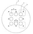
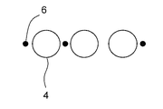
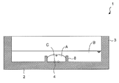
- the cell culture container 1 of the present embodiment has a bottom portion 2 and a side wall 3, and a plurality of microwells 4 for containing cells are arranged at the bottom portion. It has a cell accommodating part 5.
- identifiers 6 are attached in pairs for each microwell, and the relative positions of the identifiers with respect to the paired microwells are different for each pair of identifiers and microwells. It is characterized by that. Since the relative position of the identifier with respect to the microwell is different for each microwell, the position of the microwell in a plurality of macrowells can be specified only by observing one pair of the microwell and the identifier.
- the identifier Since the identifier is attached in the vicinity of each microwell, when observing at a high magnification, it is not necessary to greatly shift the observation position from the microwell, and quick observation is possible. Furthermore, even when cells are photographed at a high magnification, identifiers are photographed together with microwells, so there is no need to manually add information to the photograph data, avoiding complicated work, It is also possible to avoid the risk of an association error due to an operator error.
- the microwell preferably has a concave portion suitable for individually accommodating a cell such as a fertilized egg, and the size thereof is minute.
- the present invention attaches a minute identifier to each such minute microwell. It is characterized by.
- the area of the opening of each microwell in the top view of the cell culture container is preferably 3 mm 2 or less, more preferably 1 mm 2 or less, still more preferably 0.5 mm 2 or less, and preferably 0.00. 03 mm 2 or more.
- the microwell may be a recess formed by forming a recess having a wall surface and an opening, and provided directly as a recess in the bottom of the cell culture container, or a recess formed by a member protruding from the bottom.
- the area of the opening of each microwell in a top view is, in other words, the area of the figure formed by the outer edge of the opening of the microwell.
- the figure formed by the outer edge of the opening of the microwell is not particularly limited, and may be a polygonal shape such as a triangle and a quadrangle, or a circle (including a circle, a substantially circle, an ellipse, and a substantially ellipse). , Preferably circular.
- the opening width is equal to the diameter of the circle (R in FIG. 3), and the diameter is larger than the maximum dimension of the cells to be cultured.
- the diameter of the circular opening is larger than the maximum cell size of the blastocyst stage It is desirable.
- the opening width is smaller than the pitch between the microwells.
- the opening width of the opening of the microwell (or the diameter when the outer edge of the opening of the microwell is circular) is preferably 0.1 mm or more, more preferably 0.15 mm or more, and further preferably 0.2 mm. It is above, Preferably it is less than 0.6 mm, More preferably, it is less than 0.4 mm.
- the opening width of the opening of the microwell can be defined as X + m (where X represents the maximum cell diameter).
- m is preferably 0.01 mm or more, and more preferably 0.02 mm or more.
- the number of microwells is preferably 4 or more, more preferably 8 or more, for example 10 or more, preferably 50 or less, more preferably 30 or less, at the bottom of the cell culture container of the present invention. Therefore, a plurality of cells can be cultured by arranging cells such as fertilized eggs one by one in one microwell. By culturing cells such as fertilized eggs in the state where a plurality of cells are arranged close to each other in the same system, a good paracrine effect and autocrine effect can be expected.
- culturing in the same system means culturing in a culture solution that is not isolated and can be distributed, preferably in a drop of the same culture solution.
- the pitch between the microwells is preferably 1 mm or less, more preferably 0.8 mm or less, and even more preferably 0.6 mm or less.
- a device equipped with a 1/2 inch CCD element, 4, 10, and 20 times objective lens is often used.
- the observable field of view is approximately 1.6 mm ⁇ 1.2 mm, and the observation field is designed to include four or more microwells. It is preferable to do.
- the pitch between microwells is the distance between the centers of adjacent microwells (for example, a in FIG. 3).
- the center of the microwell is the center of gravity of the figure formed by the outer edge of the opening of the microwell, and if the outer edge is circular, it indicates the center of the circle.
- the pitch between the microwells usually refers to an average pitch, and the average pitch refers to a value obtained by calculating an average value from pitches with all adjacent microwells.
- the pitch between the microwells is larger than the dimension of the outer edge of the opening of the microwell.
- the dimension of the outer edge of the opening of the microwell is the diameter if the outer edge of the opening is circular, and is the minimum diameter of the figure formed by the outer edge of the opening otherwise.
- the plurality of adjacent microwells are preferably arranged in a square lattice shape or a close-packed shape.
- 25 microwells can be arranged in a 5 ⁇ 5 square lattice.
- the arrangement of the plurality of microwells may be such that a part of the arrangement is lost from a square lattice or close-packed arrangement.
- Parallelograms include squares, rectangles, rhombuses and other parallelograms.
- the phrase “microwells are arranged on the sides and vertices of the parallelogram” means that the center of gravity of the figure formed by the outer edge of the opening of the microwell is arranged on the sides and vertices of the parallelogram.
- eight microwells are arranged one by one at the four vertices of the square and one at the midpoint of the four sides.
- the position of the identifier attached in pairs with each microwell may be inside or outside the microwell, but preferably outside the microwell. This is because if it is provided inside the microwell, the observation of the fertilized egg may be hindered and the culture performance of the fertilized egg may be affected. Preferably, it attaches
- the identifier is small enough to be placed in such a gap.
- the size of the identifier is preferably smaller than the size of the microwell. Therefore, in the top view of the cell culture container, the identifier preferably has a size that fits inside the figure formed by the opening of the microwell.
- the area identifier in the top view of a cell culture vessel 30000Myuemu 2 or less, preferably 15000Myuemu 2 or less, more preferably 8000Myuemu 2 or less, preferably 100 [mu] m 2 or more.
- the identifier is attached sufficiently near the paired microwells so that it is clear which microwell is paired with. Therefore, each identifier is preferably assigned such that the distance from the paired microwells is the smallest among all the microwells.
- the distance between the identifier and the microwell is defined as the distance between the centroid of the graphic formed by the opening of the microwell and the centroid of the graphic formed by the identifier. Therefore, the distance between the identifier and the microwell is preferably larger than 1 ⁇ 2 of the opening width of the microwell and smaller than the pitch between the microwells.
- the distance between the identifier and the microwell is preferably 500 ⁇ m or less, more preferably 400 ⁇ m or less, and even more preferably 300 ⁇ m or less.
- the identifier is preferably attached to all the microwells in the cell container, but several microwells are not attached to the identifier (for example, 10% or less of the total number of microphone wells contained in the cell container). Even if included, it is included in the present invention. This is because, when cells are not accommodated and there are microwells that are not the object of observation, such microwells do not require an identifier.
- one identifier is attached to a pair of microwells, but two or more identifiers may be attached. By changing the number of identifiers attached in pairs for each microwell, the amount of information can be increased.
- the shape of the identifier is not particularly limited.
- graphics include graphics such as letters, numbers, polygons, arrows, lines (bars), dots, barcodes such as QR codes, and combinations thereof.
- an identifier having a size smaller than that of the microwell is preferably attached in the vicinity of a microwell suitable for accommodating cells such as a fertilized egg, the identifier has a simple shape that is easy to mold. Preferably there is. This is because a cell culture container is often manufactured by injection molding, so that it is difficult to mold a complicated shape with a minute size.
- the shape of the identifier is simple, that is, even if the identifier itself has a small amount of information, the position of each microwell can be specified by adding information on the relative position to the microwell. Further, if the identifier has a complicated shape, the yield in manufacturing the cell culture container may be reduced. However, by using a simple shape, it is possible to avoid a decrease in yield and to reduce the manufacturing cost.
- the shapes of the plurality of identifiers attached to one microwell may be the same or different. By attaching identifiers having different shapes, the amount of information can be increased. Different identifier shapes mean that at least one identifier having a different shape exists among a plurality of identifiers.
- the identifier preferably has a dot shape or a linear shape (bar shape).
- dot-like identifiers and linear identifiers may be mixed, and the amount of information can be increased by mixing them.
- the amount of information that the identifier itself has can be increased by changing the length of the linear identifier.
- the amount of information that the identifier itself has can also be increased by changing the direction of the identifier.
- the “direction” here is a rotation angle and is different from an angle ⁇ described later. For example, when the dots are replaced with lines (bars) in the embodiment of FIG.
- the orientation of the culture vessel can be specified using the information amount of the orientation and the angle ⁇ . Therefore, by arranging the linear identifier with its length or orientation being changed for each microwell, even if the relative position with respect to the paired microwells is not different, the specific microwells in the plurality of microwells The position can be specified. The amount of information can also be increased by combining the direction and length.
- the relative position of an identifier to its paired microwells is different for each pair of identifiers and microwells because the distance between the identifier and its paired microwells is different for each pair and the pair of identifiers It is included that the angles with respect to the microwell are different.
- the distance between the identifier and the microwell is as described above, but the angle ⁇ of the identifier with respect to the microwell can be defined as follows. For example, in the embodiment shown in FIGS. 1 to 3, when the straight line X is drawn at the bottom of the cell culture container in a top view, the angle ⁇ is a straight line parallel to the straight line X, the center of gravity of the microwell, and the identifier.
- the center of gravity of the microwell refers to the center of gravity of the figure formed by the outer edge of the opening of the microwell
- the center of gravity of the identifier refers to the center of gravity of the figure formed by the identifier.
- the position of a specific microwell in a plurality of microwells can be specified by arranging the angle ⁇ to be different for each pair of microwells and identifiers. The amount of information can be increased by combining distance and angle.
- the relative position of the identifier to the microwell is made different for each pair. It can also be arranged. For example, in the embodiment shown in FIG. 13, the vicinity of the microwell is divided into three regions, and the presence or absence of an identifier in each region differs for each pair of identifier and microwell. In the microwell C, the identifier exists only in the uppermost region and does not exist in other regions. On the other hand, in the microwell B, identifiers exist in all areas. In this manner, by changing the presence or absence of the identifier for each region, the position of a specific microwell in a plurality of microwells can be specified.
- the number of divisions is not particularly limited, but can be preferably divided into 3 to 10, more preferably 4 to 6 regions.
- the sorting method is not particularly limited, but is preferably divided into a grid having columns and rows because reading is easy.
- the number of columns is preferably 1 to 3, more preferably 1 to 2, and the number of rows is preferably 1 to 6, more preferably 3 to 5.
- the identifier When the identifier is arranged on the left or right of the microwell, the identifier can be arranged as close as possible to the position of the microwell by setting the above range.
- the identifier When the identifier is arranged above or below the microwell, the identifier can be arranged as close as possible to the position of the microwell by setting the number of rows and columns in the opposite range.
- FIG. 14 shows an embodiment in which the neighborhood of the microwell is partitioned into a grid of 2 columns and 3 rows.
- the shape of the identifier is different, and the amount of information can be further increased.
- the relative positions of at least one identifier with respect to the paired microwell are arranged so as to be different for each pair of identifier and microwell. That is, when a plurality of microwells are compared, it is sufficient that at least one identifier having different relative positions with respect to the microwells exists, and identifiers having the same relative position may exist. For example, in the embodiment shown in FIG. 13, two identifiers assigned to the microwell A and two identifiers assigned to the microwell D have the same relative position with respect to the microwell.
- Identifier b and identifier c are different in relative position with respect to the microwell, and therefore the position of the microwell can be specified.
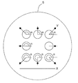
- the centroids of the plurality of identifiers are preferably arranged on a straight line, for example, like the microwells A, B, D, and F in FIG. This is because, as will be described below, the presence or absence of rotation of the cell culture container itself can be determined even when a pair of microwells and identifiers is photographed one by one at high magnification.
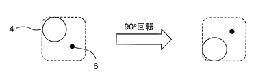
- the orientation of the cell culture container at the time of shooting must always be constant. Otherwise, the above angle ⁇ includes the inclination of the cell culture container itself, and the relative position on the cell culture container may differ, but the relative position may not be distinguished on the photograph. is there.
- a photograph (FIG. 5) of the pair of the microwell 4 and the identifier 6 arranged at the upper right apex is the microwell 4 arranged at the lower right apex in FIG. 3.
- the identifier 6 cannot be distinguished from a photograph taken by rotating the cell culture container 90 ° to the left from the state of FIG.
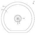
- the second identifier for identifying the orientation of the cell culture container, which is different from the identifier, to the cell culture container. Since the second identifier is used when taking a photograph, it is preferable that the second identifier can be visually confirmed. Therefore, in the top view of the cell culture container, the area of the second identifier is preferably larger than the area of the opening of the microwell. It is preferable to attach the second identifier to the outside of the cell accommodating part on the bottom part where a plurality of microwells are arranged (for example, 7 in FIG. 1). The second identifier may be attached to the side wall of the cell culture container.
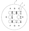
- the orientation of the cell culture container can be always constant depending on the shape of the cell culture container itself. That is, by making the outer peripheral shape of the side wall of the cell culture container into a shape that can specify the orientation of the cell culture container, for example, a shape lacking a circle (FIG. 7), the orientation of the cell culture container at the time of photographing is always constant. It is also possible. In this case, the shape of the cell culture container is not particularly limited as long as the orientation of the cell culture container can be specified.
- each identifier has a linear shape facing the same direction in the top view of the cell culture container, so that the direction of the line (bar) can be seen in the microwell-identifier pair photograph taken at high magnification. Based on the above, the orientation of the cell culture container at the time of photographing can be specified to some extent.
- the identifier is attached only to the right side, only the left side, only the upper side, or only the lower side of the microwell, so that a photograph of a pair of microwells and identifiers taken at a high magnification is obtained.
- the orientation of the cell culture container can also be specified. Since the rough position of the identifier is determined to some extent for each target microwell, it is easy to determine the shooting position when shooting a fertilized egg manually at a high magnification. If they are not in the same direction, it is necessary to determine the shooting position while searching for the position of the identifier 360 ° for each well, for example, one well is slightly left from the center and another well is slightly below the center.
- the right side, the left side, the upper side, or the lower side of the microwell can be defined as respective ranges obtained by dividing 360 ° around the center of gravity of the microwell into four parts.
- ⁇ shown in FIG. A range of ⁇ 135 ° can be defined as the upper side. Therefore, even when the identifier is attached only to the upper side of the microwell, it is possible to make the relative position different for each microwell within the range.
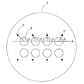
- a plurality of identifiers assigned to a plurality of microwells are arranged on the same axis.
- the plurality of microwells does not have to be all the microwells in the cell accommodating portion, and preferably 2 or more of them, more preferably 3 or more, and further preferably 4 or more, and their centroids are on the same axis.
- a plurality of identifiers attached to a plurality of microwells whose centers of gravity are on the same axis are arranged on the same axis, so that when changing microwells to be observed in high magnification observation, cells
- a pair of microwells and identifiers can be captured, so that rapid observation is possible.
- the field of view is generally horizontally long, a plurality of identifiers arranged on the horizontal axis can be observed at once (FIG. 8).
- the identifier by aligning the long side direction of the microscope field of view and the axial direction of the identifier, all identifiers can be observed even when observing at a higher magnification. For example, it is particularly advantageous when the short-side distance of the visual field is just the diameter of the microwell.
- the identifier attached to the lower part of the rightmost microwell may be out of the field of view.
- each microwell is arranged one by one at the four vertices of the square and one at the midpoint of the four sides to form a cell storage unit. Yes.
- One dot-like identifier is attached in the vicinity of each microwell.
- the angle ⁇ of the identifier with respect to the microwell differs for each pair, the position of each microwell can be specified only by observing the pair of microwells and the identifier.
- microwells are arranged one by one at the four vertices of the rectangle, and two microwells are arranged at equal intervals only on two of the four sides.
- positioned at square lattice shape is comprised.
- One dot-like identifier is attached in the vicinity of each microwell.
- the angle ⁇ of the identifier with respect to the microwell differs for each pair, the position of each microwell can be specified only by observing the pair of microwells and the identifier.
- the upper four identifiers assigned to the microwells whose centroids are arranged on the same axis are arranged on the same axis.
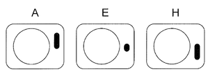
- FIG. 12 represents a micrograph of a microwell and identifier pair at positions A, E, and H, respectively, in FIG.
- the distance between the identifier and the microwell is substantially the same for any pair, but the angle ⁇ and / or the length of the line (bar) of the identifier with respect to the microwell is different for each pair.
- each identifier is linear in the same direction and attached to the right side with respect to the microwell, the identifier is also displayed in a pair of microwell and identifier photographs taken at high magnification.
- the orientation of the cell culture container at the time of photographing can be specified based on the position of the image and the direction of the line (bar).
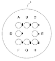
- microwells are arranged one by one at the four vertices of the square and one at the midpoint of the four sides. Is configured.
- One, two, or three dot-like identifiers are attached to each microwell as a pair, and the relative position of at least one identifier with respect to the paired microwell is determined by the identifier and the microwell. Each pair is different.
- the neighborhood of the microwell is divided into three regions, and the presence or absence of an identifier in each region is different for each pair of identifier and microwell.
- the position of the well can be specified.
- region in FIG. 13 is notional, and does not need to exist actually.
- the vicinity of each microwell may be divided into four regions, and identifier groups may be arranged so that the presence or absence of dots in each region is different.
- identifier groups may be arranged so that the presence or absence of dots in each region is different.
- FIG. 13 since there is no identifier in any area, there is a microwell for identifying the position.
- photography can be recognized from the relative position with respect to the dot of the 4th line about every microwell.
- the shape of only the dot in the fourth column may be changed.
- the cell culture container of the present invention has a bottom portion and a side wall, and can store a liquid in a space formed by the bottom portion and the side wall.
- the shape of the bottom is not particularly limited, and may be a polygonal shape such as a triangle or a quadrangle, or may be a circle (including a circle, a substantially circle, an ellipse, or a substantially ellipse), and the side wall surrounds the outer edge of the bottom. Formed.
- the side opposite the bottom is open, and the shape of the opening is preferably the same as the shape of the bottom.
- an opening having a circular shape and an opening width (for example, r in FIG. 2) of preferably 30 to 60 mm, particularly 35 mm is used.
- the cell culture container may have a lid
- the wall surface of the recess forming the microwell has an inclined surface that becomes higher as it goes from the deepest part to the outer edge.
- the shape (profile) of the inclined surface can be appropriately adopted, for example, when it becomes higher in a curved shape from the lowest position of the concave portion formed by the microwell toward the outer edge of the concave portion, when it becomes higher in a stepped shape, etc.
- Such an inclined surface preferably forms a conical surface or a side surface of a truncated cone.
- the conical surface is formed, the deepest part of the microwell is configured such that the cone is arranged so as to correspond to the apex of the cone. In this case, the deepest part of the microwell, that is, the apex of the cone may be rounded.
- the truncated cone is arranged so that the smaller of the upper surface and the lower surface of the truncated cone corresponds to the deepest part of the microwell.
- the depth of the microwell means a depth measured vertically from the opening of the microwell to the deepest portion, and is preferably 0.05 to 0.5 mm. If the depth of the microwell is too shallow, the cells may move when the culture vessel is transported or when the cells divide, and the cells may come out of the microwell range. It is set so that it can be maintained. For example, in order to retain the cells in the microwell, the depth is preferably 1/3 or more of the maximum cell diameter, and more preferably 1/2 or more. On the other hand, if the depth is too deep, it becomes difficult to introduce the culture solution or cells into the microwell. Therefore, the value is appropriately set so that the value is not too deep while the cells are held in the microwell.
- the upper limit of the depth can be 3 times or less the opening width of the opening of the microwell.
- the depth is preferably not more than 1 times the opening width of the microwell, and particularly preferably not more than 1/2.
- the surface roughness of the wall surface of the microwell, particularly the inclined surface is large, a clear contour is generated due to unevenness on the inclined surface when the image observed through the microscope is subjected to contour extraction processing. Since it may not be obtained, the value is preferably as small as possible.
- the maximum height Ry extract only the reference length from the roughness curve in the direction of the average line, which means the interval between the peak line and the valley line in the extracted part
- the surface roughness of the inclined surface can be reduced by increasing the processing accuracy of the mold, for example, by performing a polishing process when producing the mold for the culture vessel.
- a plurality of microwells are arranged at the bottom of the cell culture container to constitute a cell storage unit.
- a plurality of groups of cell accommodating parts composed of groups of such microwells may be arranged at the bottom, and these groups may not be close to each other.
- the cell accommodating part in which a plurality of microwells are arranged may be separated from other parts in the culture vessel by an inner wall surrounding them (for example, 8 in FIGS. 1 and 2).
- each group is preferably surrounded by an inner wall.
- the culture solution containing the fertilized egg is formed in a culture vessel, and the culture solution is prevented from drying by covering the droplet with oil.
- the material of the cell culture vessel is not particularly limited. Specifically, inorganic materials such as metal, glass, and silicon, plastics (for example, polystyrene resin, polyethylene resin, polypropylene resin, ABS resin, nylon, acrylic resin, fluororesin, polycarbonate resin, polyurethane resin, methylpentene resin, And organic materials represented by phenol resin, melamine resin, epoxy resin, and vinyl chloride resin).
- plastics for example, polystyrene resin, polyethylene resin, polypropylene resin, ABS resin, nylon, acrylic resin, fluororesin, polycarbonate resin, polyurethane resin, methylpentene resin, And organic materials represented by phenol resin, melamine resin, epoxy resin, and vinyl chloride resin.
- the cell culture vessel can be produced by a method known to those skilled in the art. For example, when a culture container made of a plastic material is manufactured, it can be manufactured by a conventional molding method such as injection molding.
- the cell culture vessel is preferably subjected to surface hydrophilization treatment such as plasma treatment from the viewpoint of preventing non-specific adhesion of the cultured cells and preventing the drop of the culture solution from being biased by surface tension.
- surface hydrophilization treatment such as plasma treatment from the viewpoint of preventing non-specific adhesion of the cultured cells and preventing the drop of the culture solution from being biased by surface tension.
- the number of bacteria (bioburden number) adhering to the container after production is preferably 100 cfu / container or less. Further, it is more preferable that sterilization treatment such as ⁇ -ray sterilization is performed.
- the cell culture container may be surface-treated or surface-coated so as to promote the development of fertilized eggs.
- the cell culture vessel in order to promote the development of a fertilized egg, when co-culturing with cells of other organs (for example, endometrial cells or fallopian tube epithelial cells), it is necessary to adhere these cells to a culture vessel in advance. . In such a case, it is advantageous to coat the surface of the culture vessel with a cell adhesive material.
- the cells to be cultured are not particularly limited, and examples include fertilized eggs, egg cells, ES cells (embryonic stem cells), and iPS cells (artificial pluripotent stem cells).
- An egg cell refers to an unfertilized egg cell, and includes an immature oocyte and a mature oocyte. After fertilization, the fertilized egg increases in number of cells from the 2 cell stage, the 4 cell stage, and the 8 cell stage by cleavage, and develops into a blastocyst through a morula.
- Fertilized eggs include early embryos such as 2-cell embryos, 4-cell embryos and 8-cell embryos, morulas, blastocysts (including early blastocysts, expanded blastocysts and escaped blastocysts).
- a blastocyst means an embryo composed of external cells with the potential to form the placenta and internal cell masses with the potential to form embryos.
- ES cells refer to undifferentiated pluripotent or totipotent cells obtained from the inner cell mass of a blastocyst.
- An iPS cell refers to a cell having a pluripotency similar to that of an ES cell by introducing several types of genes (transcription factors) into somatic cells (mainly fibroblasts). That is, the cell includes an aggregate of a plurality of cells such as a fertilized egg and a blastocyst.
- the cell culture container of the present invention is preferably suitable for culturing mammalian and avian cells, particularly mammalian cells.
- Mammals refer to warm-blooded vertebrates, eg, primates such as humans and monkeys, rodents such as mice, rats and rabbits, pets such as dogs and cats, and livestock such as cattle, horses and pigs. Is mentioned.
- the cell culture container of the present invention is particularly suitable for culturing human fertilized eggs.
- Cultivation is usually carried out by placing the cell culture vessel in an incubator that provides an environmental atmosphere containing gas necessary for the growth and maintenance of the cultured cells and a constant environmental temperature.
- Necessary gases include water vapor, free oxygen (O 2 ) and carbon dioxide (CO 2 ).
- O 2 free oxygen
- CO 2 carbon dioxide
- a stable pH is obtained by a stable CO 2 content and a stable temperature.
- a fertilized egg when a fertilized egg is cultured, it is usually determined whether it is a high-quality fertilized egg suitable for transplantation into the uterus after the culture.
- the determination may be performed automatically or manually with a microscope or the like.
- an image of the cells in the culture vessel obtained by a microscope is picked up by a detection device such as a CCD camera, the obtained image is subjected to contour extraction processing, and corresponds to the cells in the image
- the quality can be determined by extracting the portion and analyzing the extracted cell image with an image analysis apparatus.
- the image contour extraction processing for example, the processing described in JP-A-2006-337110 can be used.
- the cell When the microwell consists of a bottom surface parallel to the bottom of the cell culture container and a side surface perpendicular thereto, the cell may move in the microwell and come into contact with the side surface.
- the wall surface of the microwell when the wall surface of the microwell has an inclined surface, it preferably includes a conical or frustoconical portion. In this case, cells to be cultured automatically exist at the bottom of the microwell, and even if the microwell has a side surface perpendicular to the bottom of the cell culture container on the opening side from the inclined surface, It does not remain in contact with this, and the contour extraction process of the captured cell image can be performed without any problem.
- Cell culture container 2 Side wall 3: Bottom part 4: Microerowell 5: Cell accommodating part 6: Identifier 7: Second identifier 8: Inner wall r: Opening width of cell culture container R: Opening width of microwell a: Micro Well pitch A: culture B: oil C: cells
Landscapes
- Health & Medical Sciences (AREA)
- Life Sciences & Earth Sciences (AREA)
- Chemical & Material Sciences (AREA)
- Wood Science & Technology (AREA)
- Zoology (AREA)
- Bioinformatics & Cheminformatics (AREA)
- Organic Chemistry (AREA)
- Engineering & Computer Science (AREA)
- Genetics & Genomics (AREA)
- Sustainable Development (AREA)
- Microbiology (AREA)
- Biotechnology (AREA)
- Biochemistry (AREA)
- General Engineering & Computer Science (AREA)
- General Health & Medical Sciences (AREA)
- Biomedical Technology (AREA)
- Clinical Laboratory Science (AREA)
- Molecular Biology (AREA)
- Analytical Chemistry (AREA)
- Immunology (AREA)
- Apparatus Associated With Microorganisms And Enzymes (AREA)
Priority Applications (3)
| Application Number | Priority Date | Filing Date | Title |
|---|---|---|---|
| ES14843661T ES2898082T3 (es) | 2013-09-11 | 2014-08-21 | Recipiente de cultivo celular |
| US14/917,799 US10557111B2 (en) | 2013-09-11 | 2014-08-21 | Cell culture vessel |
| EP14843661.1A EP3045526B1 (en) | 2013-09-11 | 2014-08-21 | Cell culture vessel |
Applications Claiming Priority (4)
| Application Number | Priority Date | Filing Date | Title |
|---|---|---|---|
| JP2013-188205 | 2013-09-11 | ||
| JP2013188205 | 2013-09-11 | ||
| JP2014027771A JP5920375B2 (ja) | 2013-09-11 | 2014-02-17 | 細胞培養容器 |
| JP2014-027771 | 2014-02-17 |
Publications (1)
| Publication Number | Publication Date |
|---|---|
| WO2015037407A1 true WO2015037407A1 (ja) | 2015-03-19 |
Family
ID=52665524
Family Applications (1)
| Application Number | Title | Priority Date | Filing Date |
|---|---|---|---|
| PCT/JP2014/071879 Ceased WO2015037407A1 (ja) | 2013-09-11 | 2014-08-21 | 細胞培養容器 |
Country Status (5)
| Country | Link |
|---|---|
| US (1) | US10557111B2 (enExample) |
| EP (1) | EP3045526B1 (enExample) |
| JP (1) | JP5920375B2 (enExample) |
| ES (1) | ES2898082T3 (enExample) |
| WO (1) | WO2015037407A1 (enExample) |
Cited By (4)
| Publication number | Priority date | Publication date | Assignee | Title |
|---|---|---|---|---|
| JP2015053878A (ja) * | 2013-09-11 | 2015-03-23 | 大日本印刷株式会社 | 培養容器 |
| JP2017123801A (ja) * | 2016-01-13 | 2017-07-20 | 大日本印刷株式会社 | 細胞取扱容器 |
| JP2021006066A (ja) * | 2020-10-26 | 2021-01-21 | 憲隆 福永 | 胚培養装置およびその撮像装置 |
| US20210222108A1 (en) * | 2018-09-04 | 2021-07-22 | Universidade De Santiago De Compostela | Organoid culture system and method for sterilising an organoid culture system |
Families Citing this family (6)
| Publication number | Priority date | Publication date | Assignee | Title |
|---|---|---|---|---|
| JP2017153373A (ja) * | 2016-02-29 | 2017-09-07 | 株式会社ワークス | 細胞検査部材 |
| JP1586945S (enExample) * | 2017-03-31 | 2020-09-28 | ||
| JP2019216708A (ja) * | 2018-06-14 | 2019-12-26 | 株式会社リコー | 細胞含有容器及び細胞含有容器の製造方法、並びに、細胞チップ |
| CN109055213A (zh) * | 2018-08-14 | 2018-12-21 | 深圳职业技术学院 | 一种简易微量细胞培养和计数的装置及该装置的制作方法 |
| CN212713572U (zh) * | 2020-06-02 | 2021-03-16 | 深圳韦拓生物科技有限公司 | 一种细胞培养皿 |
| US11781105B2 (en) * | 2020-06-05 | 2023-10-10 | National Guard Health Affairs | Method, system, and apparatus using centrifugation to accumulate and collect biological samples |
Citations (4)
| Publication number | Priority date | Publication date | Assignee | Title |
|---|---|---|---|---|
| JP2006129713A (ja) * | 2004-11-02 | 2006-05-25 | Morinaga Milk Ind Co Ltd | 培地入りシャーレ及びその製造管理方法 |
| JP2006280298A (ja) * | 2005-04-01 | 2006-10-19 | Nipro Corp | 細胞培養用容器 |
| JP2006337110A (ja) | 2005-05-31 | 2006-12-14 | Ngk Spark Plug Co Ltd | ガスセンサ |
| JP2010200748A (ja) * | 2009-02-09 | 2010-09-16 | Dainippon Printing Co Ltd | 細胞培養容器 |
Family Cites Families (8)
| Publication number | Priority date | Publication date | Assignee | Title |
|---|---|---|---|---|
| US5749730A (en) * | 1996-02-20 | 1998-05-12 | Jordco, Inc. | Dental organizer for light-sensitive materials |
| DE10244424B4 (de) * | 2002-09-24 | 2008-07-31 | Ivoclar Vivadent Ag | Auftragvorrichtung |
| EP2381255A1 (en) * | 2003-09-25 | 2011-10-26 | Toyama Prefecture | Microwell array chip and its manufacturing method |
| US7331450B2 (en) * | 2004-11-30 | 2008-02-19 | Centrix, Inc. | Dental applicator holding and material dispensing tray |
| US7682816B2 (en) * | 2005-04-07 | 2010-03-23 | 454 Life Sciences Corporation | Thin film coated microwell arrays and methods of using same |
| EP1872854A1 (en) * | 2006-06-30 | 2008-01-02 | PerkinElmer, Inc. | Improved multi-well assay plate |
| JP2012060903A (ja) * | 2010-09-14 | 2012-03-29 | Kajixx Kk | マルチウエルプレート用粘着シート及び細胞培養方法 |
| GB201103665D0 (en) * | 2011-03-04 | 2011-04-13 | Univ Cardiff | Correlative microscopy |
-
2014
- 2014-02-17 JP JP2014027771A patent/JP5920375B2/ja active Active
- 2014-08-21 EP EP14843661.1A patent/EP3045526B1/en active Active
- 2014-08-21 US US14/917,799 patent/US10557111B2/en active Active
- 2014-08-21 WO PCT/JP2014/071879 patent/WO2015037407A1/ja not_active Ceased
- 2014-08-21 ES ES14843661T patent/ES2898082T3/es active Active
Patent Citations (5)
| Publication number | Priority date | Publication date | Assignee | Title |
|---|---|---|---|---|
| JP2006129713A (ja) * | 2004-11-02 | 2006-05-25 | Morinaga Milk Ind Co Ltd | 培地入りシャーレ及びその製造管理方法 |
| JP2006280298A (ja) * | 2005-04-01 | 2006-10-19 | Nipro Corp | 細胞培養用容器 |
| JP2006337110A (ja) | 2005-05-31 | 2006-12-14 | Ngk Spark Plug Co Ltd | ガスセンサ |
| JP2010200748A (ja) * | 2009-02-09 | 2010-09-16 | Dainippon Printing Co Ltd | 細胞培養容器 |
| JP4724854B2 (ja) | 2009-02-09 | 2011-07-13 | 大日本印刷株式会社 | 細胞培養容器 |
Non-Patent Citations (1)
| Title |
|---|
| See also references of EP3045526A4 |
Cited By (4)
| Publication number | Priority date | Publication date | Assignee | Title |
|---|---|---|---|---|
| JP2015053878A (ja) * | 2013-09-11 | 2015-03-23 | 大日本印刷株式会社 | 培養容器 |
| JP2017123801A (ja) * | 2016-01-13 | 2017-07-20 | 大日本印刷株式会社 | 細胞取扱容器 |
| US20210222108A1 (en) * | 2018-09-04 | 2021-07-22 | Universidade De Santiago De Compostela | Organoid culture system and method for sterilising an organoid culture system |
| JP2021006066A (ja) * | 2020-10-26 | 2021-01-21 | 憲隆 福永 | 胚培養装置およびその撮像装置 |
Also Published As
| Publication number | Publication date |
|---|---|
| US20160222335A1 (en) | 2016-08-04 |
| EP3045526B1 (en) | 2021-10-27 |
| EP3045526A4 (en) | 2017-05-03 |
| ES2898082T3 (es) | 2022-03-03 |
| EP3045526A1 (en) | 2016-07-20 |
| JP5920375B2 (ja) | 2016-05-18 |
| JP2015077121A (ja) | 2015-04-23 |
| US10557111B2 (en) | 2020-02-11 |
Similar Documents
| Publication | Publication Date | Title |
|---|---|---|
| JP5920375B2 (ja) | 細胞培養容器 | |
| JP4724854B2 (ja) | 細胞培養容器 | |
| JP6344461B2 (ja) | 細胞培養容器 | |
| JP6657729B2 (ja) | 細胞取扱容器 | |
| JP2015029431A (ja) | 細胞培養容器 | |
| JP5920296B2 (ja) | 細胞培養容器 | |
| JP6278590B2 (ja) | 細胞培養容器および細胞培養方法 | |
| JP6060625B2 (ja) | 細胞培養容器および細胞観察方法 | |
| JP6384501B2 (ja) | 細胞培養容器 | |
| JP6349847B2 (ja) | 細胞培養容器 | |
| JP2016082987A (ja) | 細胞培養容器 | |
| JP6364817B2 (ja) | 細胞培養容器 | |
| JP6451728B2 (ja) | 細胞培養容器および細胞観察方法 | |
| JP6379529B2 (ja) | 細胞培養容器 | |
| JP6330278B2 (ja) | 培養容器 | |
| JP6244747B2 (ja) | 特定の配列のマイクロウェルを有する細胞培養容器 | |
| JP6187065B2 (ja) | 細胞培養容器 | |
| JP6277639B2 (ja) | 培養容器 | |
| JP2017123801A (ja) | 細胞取扱容器 | |
| JP6326905B2 (ja) | 細胞培養容器 | |
| JP6892215B2 (ja) | 細胞取扱容器 | |
| JP2020072745A (ja) | 細胞取扱容器 |
Legal Events
| Date | Code | Title | Description |
|---|---|---|---|
| 121 | Ep: the epo has been informed by wipo that ep was designated in this application |
Ref document number: 14843661 Country of ref document: EP Kind code of ref document: A1 |
|
| WWE | Wipo information: entry into national phase |
Ref document number: 14917799 Country of ref document: US |
|
| NENP | Non-entry into the national phase |
Ref country code: DE |
|
| REEP | Request for entry into the european phase |
Ref document number: 2014843661 Country of ref document: EP |
|
| WWE | Wipo information: entry into national phase |
Ref document number: 2014843661 Country of ref document: EP |