WO2015029984A1 - 油圧緩衝器 - Google Patents
油圧緩衝器 Download PDFInfo
- Publication number
- WO2015029984A1 WO2015029984A1 PCT/JP2014/072262 JP2014072262W WO2015029984A1 WO 2015029984 A1 WO2015029984 A1 WO 2015029984A1 JP 2014072262 W JP2014072262 W JP 2014072262W WO 2015029984 A1 WO2015029984 A1 WO 2015029984A1
- Authority
- WO
- WIPO (PCT)
- Prior art keywords
- valve
- cylinder
- hydraulic shock
- shock absorber
- oil
- Prior art date
Links
Images


Classifications
-
- B—PERFORMING OPERATIONS; TRANSPORTING
- B60—VEHICLES IN GENERAL
- B60G—VEHICLE SUSPENSION ARRANGEMENTS
- B60G17/00—Resilient suspensions having means for adjusting the spring or vibration-damper characteristics, for regulating the distance between a supporting surface and a sprung part of vehicle or for locking suspension during use to meet varying vehicular or surface conditions, e.g. due to speed or load
- B60G17/06—Characteristics of dampers, e.g. mechanical dampers
- B60G17/08—Characteristics of fluid dampers
-
- B—PERFORMING OPERATIONS; TRANSPORTING
- B60—VEHICLES IN GENERAL
- B60G—VEHICLE SUSPENSION ARRANGEMENTS
- B60G15/00—Resilient suspensions characterised by arrangement, location or type of combined spring and vibration damper, e.g. telescopic type
- B60G15/02—Resilient suspensions characterised by arrangement, location or type of combined spring and vibration damper, e.g. telescopic type having mechanical spring
- B60G15/06—Resilient suspensions characterised by arrangement, location or type of combined spring and vibration damper, e.g. telescopic type having mechanical spring and fluid damper
- B60G15/061—Resilient suspensions characterised by arrangement, location or type of combined spring and vibration damper, e.g. telescopic type having mechanical spring and fluid damper with a coil spring being mounted inside the damper
-
- F—MECHANICAL ENGINEERING; LIGHTING; HEATING; WEAPONS; BLASTING
- F16—ENGINEERING ELEMENTS AND UNITS; GENERAL MEASURES FOR PRODUCING AND MAINTAINING EFFECTIVE FUNCTIONING OF MACHINES OR INSTALLATIONS; THERMAL INSULATION IN GENERAL
- F16F—SPRINGS; SHOCK-ABSORBERS; MEANS FOR DAMPING VIBRATION
- F16F13/00—Units comprising springs of the non-fluid type as well as vibration-dampers, shock-absorbers, or fluid springs
- F16F13/005—Units comprising springs of the non-fluid type as well as vibration-dampers, shock-absorbers, or fluid springs comprising both a wound spring and a damper, e.g. a friction damper
- F16F13/007—Units comprising springs of the non-fluid type as well as vibration-dampers, shock-absorbers, or fluid springs comprising both a wound spring and a damper, e.g. a friction damper the damper being a fluid damper
-
- F—MECHANICAL ENGINEERING; LIGHTING; HEATING; WEAPONS; BLASTING
- F16—ENGINEERING ELEMENTS AND UNITS; GENERAL MEASURES FOR PRODUCING AND MAINTAINING EFFECTIVE FUNCTIONING OF MACHINES OR INSTALLATIONS; THERMAL INSULATION IN GENERAL
- F16F—SPRINGS; SHOCK-ABSORBERS; MEANS FOR DAMPING VIBRATION
- F16F9/00—Springs, vibration-dampers, shock-absorbers, or similarly-constructed movement-dampers using a fluid or the equivalent as damping medium
- F16F9/32—Details
- F16F9/48—Arrangements for providing different damping effects at different parts of the stroke
- F16F9/49—Stops limiting fluid passage, e.g. hydraulic stops or elastomeric elements inside the cylinder which contribute to changes in fluid damping
-
- F—MECHANICAL ENGINEERING; LIGHTING; HEATING; WEAPONS; BLASTING
- F16—ENGINEERING ELEMENTS AND UNITS; GENERAL MEASURES FOR PRODUCING AND MAINTAINING EFFECTIVE FUNCTIONING OF MACHINES OR INSTALLATIONS; THERMAL INSULATION IN GENERAL
- F16F—SPRINGS; SHOCK-ABSORBERS; MEANS FOR DAMPING VIBRATION
- F16F9/00—Springs, vibration-dampers, shock-absorbers, or similarly-constructed movement-dampers using a fluid or the equivalent as damping medium
- F16F9/32—Details
- F16F9/50—Special means providing automatic damping adjustment, i.e. self-adjustment of damping by particular sliding movements of a valve element, other than flexions or displacement of valve discs; Special means providing self-adjustment of spring characteristics
- F16F9/512—Means responsive to load action, i.e. static load on the damper or dynamic fluid pressure changes in the damper, e.g. due to changes in velocity
- F16F9/5126—Piston, or piston-like valve elements
-
- F—MECHANICAL ENGINEERING; LIGHTING; HEATING; WEAPONS; BLASTING
- F16—ENGINEERING ELEMENTS AND UNITS; GENERAL MEASURES FOR PRODUCING AND MAINTAINING EFFECTIVE FUNCTIONING OF MACHINES OR INSTALLATIONS; THERMAL INSULATION IN GENERAL
- F16F—SPRINGS; SHOCK-ABSORBERS; MEANS FOR DAMPING VIBRATION
- F16F9/00—Springs, vibration-dampers, shock-absorbers, or similarly-constructed movement-dampers using a fluid or the equivalent as damping medium
- F16F9/32—Details
- F16F9/58—Stroke limiting stops, e.g. arranged on the piston rod outside the cylinder
- F16F9/585—Stroke limiting stops, e.g. arranged on the piston rod outside the cylinder within the cylinder, in contact with working fluid
-
- B—PERFORMING OPERATIONS; TRANSPORTING
- B60—VEHICLES IN GENERAL
- B60G—VEHICLE SUSPENSION ARRANGEMENTS
- B60G2202/00—Indexing codes relating to the type of spring, damper or actuator
- B60G2202/30—Spring/Damper and/or actuator Units
-
- B—PERFORMING OPERATIONS; TRANSPORTING
- B60—VEHICLES IN GENERAL
- B60G—VEHICLE SUSPENSION ARRANGEMENTS
- B60G2206/00—Indexing codes related to the manufacturing of suspensions: constructional features, the materials used, procedures or tools
- B60G2206/01—Constructional features of suspension elements, e.g. arms, dampers, springs
- B60G2206/40—Constructional features of dampers and/or springs
-
- F—MECHANICAL ENGINEERING; LIGHTING; HEATING; WEAPONS; BLASTING
- F16—ENGINEERING ELEMENTS AND UNITS; GENERAL MEASURES FOR PRODUCING AND MAINTAINING EFFECTIVE FUNCTIONING OF MACHINES OR INSTALLATIONS; THERMAL INSULATION IN GENERAL
- F16F—SPRINGS; SHOCK-ABSORBERS; MEANS FOR DAMPING VIBRATION
- F16F9/00—Springs, vibration-dampers, shock-absorbers, or similarly-constructed movement-dampers using a fluid or the equivalent as damping medium
- F16F9/06—Springs, vibration-dampers, shock-absorbers, or similarly-constructed movement-dampers using a fluid or the equivalent as damping medium using both gas and liquid
- F16F9/062—Bi-tubular units
-
- F—MECHANICAL ENGINEERING; LIGHTING; HEATING; WEAPONS; BLASTING
- F16—ENGINEERING ELEMENTS AND UNITS; GENERAL MEASURES FOR PRODUCING AND MAINTAINING EFFECTIVE FUNCTIONING OF MACHINES OR INSTALLATIONS; THERMAL INSULATION IN GENERAL
- F16F—SPRINGS; SHOCK-ABSORBERS; MEANS FOR DAMPING VIBRATION
- F16F9/00—Springs, vibration-dampers, shock-absorbers, or similarly-constructed movement-dampers using a fluid or the equivalent as damping medium
- F16F9/32—Details
- F16F9/58—Stroke limiting stops, e.g. arranged on the piston rod outside the cylinder
Definitions
- the present invention relates to a hydraulic shock absorber used in a passenger car, a lorry, a two-wheeled vehicle and the like.
- FIG. 1 is a diagram showing an example of a conventional configuration using a bump stop rubber as described above in a hydraulic shock absorber.
- the hydraulic shock absorber shown in FIG. 1 first shakes the upper mount 1 for fixing the hydraulic shock absorber to the vehicle body, the upper spring seat 2 disposed below the upper mount 1, the upper mount 1 and the upper spring seat 2 It comprises a piston rod 3 which is movably fixed, a cylinder 5 having an oil chamber 4 and the like.
- the hydraulic shock absorber shown in FIG. 1 further includes a piston valve 6 for dividing the oil chamber 4 in the cylinder 5 into oil chambers 4a and 4b, an outer cylinder 7 covering the outer periphery of the cylinder 5, and a piston rod 3 inserted in the central hole.
- An outer peripheral portion is provided with a bump stopper 8 which is fitted and fixed to the upper end portion of the outer cylinder 7.
- the bump stop rubber 9 is made of, for example, an elastic member such as a resin.
- the bump stop rubber 9 functions as a cushion for the upper spring sheet 2 and the bumps It functions to prevent direct contact with the stopper 8.
- the shock generated in the shock absorber at the time of the maximum compression of the shock absorber can be obtained by providing unevenness on at least one of the mutually abutting surfaces of the bump stop rubber or the bump stopper. It is intended to mitigate more effectively.
- the hydraulic shock absorber not only contacts the upper spring sheet and the bump stopper via the bump stop rubber at the time of the maximum compression but also compresses the bump stop rubber which is an elastic body.
- the present invention solves the above-mentioned conventional problems, and the hydraulic shock absorber of the present invention has an appropriate load characteristic according to the load even near the time of maximum compression, and the configuration is minimized. It is an object of the present invention to provide an inexpensive position- and speed-dependent hydraulic shock absorber that can easily change the damping force characteristics including the operating point.
- the damping force is a force that acts to suppress the vibration in proportion to the vibration velocity.
- the magnitude of the damping force is represented by the resistance speed generated according to the piston speed advancing and retracting into the cylinder, that is, the expansion and contraction speed of the shock absorber.
- a hydraulic shock absorber comprises: a cylinder; oil filled in the cylinder to be enclosed and forming an oil chamber in the cylinder; and a piston rod advancing and retracting the oil chamber
- a piston valve fixed to the tip of the piston rod and defining the oil chamber into upper and lower oil chambers and advancing and retracting in sliding contact with the inner periphery of the cylinder as the piston rod advances and retracts;
- An outer cylinder covering the outer periphery of the cylinder, a gap between an inner peripheral surface of the outer cylinder and an outer peripheral surface of the cylinder, a reservoir chamber in which oil and gas are sealed, and a bottom of the outer cylinder sealed from the outside Bottom valve, a base valve having a first compression side port and a second compression side port held by the bottom stopper and communicating the lower oil chamber with the reservoir chamber, and a first spiral spring for the base valve
- the hydraulic shock absorber comprises: a cylinder; an oil liquid filled in the cylinder to be enclosed therein to form an oil chamber; and a piston for advancing and retracting the oil chamber.
- a rod, and a piston valve fixed to the tip of the piston rod and defining the oil chamber into upper and lower oil chambers and advancing and retracting with the inner circumference of the cylinder as the piston rod advances and retracts
- An outer cylinder covering the outer periphery of the cylinder, a gap between an inner peripheral surface of the outer cylinder and an outer peripheral surface of the cylinder, a reservoir chamber in which oil and gas are enclosed, and a bottom portion of the outer cylinder from the outside
- a bottom stopper to be sealed a base valve having a first compression side port held by the bottom stopper and communicating the lower oil chamber with the reservoir chamber, and holding the base valve via a first helical spring Second
- the valve is held by the first valve and interposed between the first valve and the piston valve, and when pressed by the piston valve,
- a second helical spring that pushes down the first valve against the force to close the first compression side port, an annular main body portion, and an upper end of the second helical spring at a lower end portion of the main body portion Stopping, sliding the outer peripheral surface of the main body portion to the inner peripheral surface of the cylinder, and engaging a second spiral spring guide engaged with the lower end portion of the piston rod advancing into the cylinder; the first valve and A second valve disposed through the center of the base valve and adjusting the flow rate of the fluid with the reservoir chamber when the pressure in the lower oil chamber of the cylinder exceeds a predetermined value due to an external load And above the first valve Between the through hole through which the second valve of the first valve penetrates and the outer periphery of the second valve, and prior to adjustment of the flow rate of the fluid by the second valve, And a third valve configured to adjust the flow rate of the fluid with the reservoir chamber according to a predetermined pressure of the lower oil chamber.
- the present invention uses the pressure oil damping force to have an appropriate load characteristic according to the load even near the time of maximum compression, and the dimension for stacking internal components that determine the maximum compression position of the hydraulic shock absorber. Even with the configuration minimized, the damping force is adjusted according to the external load, and it is possible to obtain an appropriate damping force according to the load before and after recompression, so the operating point It is possible to provide an inexpensive position- and speed-dependent hydraulic shock absorber which can easily change damping force characteristics including
- the present invention it is possible to obtain an appropriate damping force according to the load at any position during compression of the hydraulic shock absorber. Further, by using a spring in the cylinder, the structure can be simplified, and it is possible to provide a position and speed dependent hydraulic shock absorber with a reduced number of parts and a suppressed increase in size.
- FIG. 2B is an enlarged view of a portion enclosed by a dotted line a in FIG. 2A.
- FIG. 3 is an enlarged view of a portion enclosed by a dashed line b in FIG.
- FIG. 2B is a state diagram of a portion corresponding to FIG.
- FIG. 4 is a state diagram of a portion corresponding to FIG. 2B in the operating state of FIG. 3A.
- FIG. 4 is a state diagram of a portion corresponding to FIG. 2C in the operating state of FIG. 3A. It is a state diagram of a part corresponding to Drawing 2A in an operation state when compression to a hydraulic shock absorber concerning Example 1 continues, and it will be in a high load state.
- FIG. 5 is a state diagram of a portion corresponding to FIG. 2B in the operating state of FIG. 4A.
- FIG. 5 is a state diagram of a portion corresponding to FIG. 2C in the operating state of FIG. 4A.
- FIG. 2B is a state diagram of a portion corresponding to FIG. 2A in an operation state when the piston rod has approached to the maximum stroke in compression to the hydraulic shock absorber according to the first embodiment.
- FIG. 6 is a state diagram of a portion corresponding to FIG. 2B in the operation state of FIG. 5A.
- FIG. 6 is a state diagram of a portion corresponding to FIG. 2C in the operating state of FIG. 5A.
- FIG. 6B is an enlarged view of a portion enclosed by a dotted line a in FIG. 6A.
- FIG. 6C is an enlarged view of a portion surrounded by a dotted line b in FIG. 6B. It is a phase diagram which shows the flow of the oil fluid in the expansion
- FIG. 6C is a state diagram of a portion corresponding to FIG. 6A in an operation state when the hydraulic pressure buffer according to the second embodiment is compressed and a load starts to be applied.
- 7B is a state diagram of a portion corresponding to FIG. 6B in the operating state of FIG. 7A.
- FIG. 7C is a state diagram of a portion corresponding to FIG. 6C in the operation state of FIG. 7A.
- FIG. 9 is a state diagram of a portion corresponding to FIG. 6B in the operation state of FIG. 8A.
- FIG. 9 is a state diagram of a portion corresponding to FIG. 6C in the operation state of FIG. 8A.
- FIG. 6C is a state diagram of a portion corresponding to FIG. 6A in an operation state when the piston rod has approached to the maximum stroke in compression to the hydraulic shock absorber according to the second embodiment.
- FIG. 10 is a state diagram of a portion corresponding to FIG. 6B in the operation state of FIG. 9A.
- FIG. 10 is a state diagram of a portion corresponding to FIG. 6C in the operation state of FIG. 9A. It is a state diagram in an operation state when a hydraulic shock absorber concerning Example 3 is compressed and it starts loading.
- FIG. 10B is an enlarged view of a portion surrounded by a dotted line a in FIG. 10A. It is an enlarged view of the part shown encircled with the broken line b of FIG. 10B.
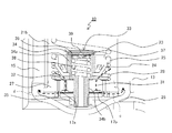
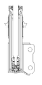
- FIG. 2A is a cross-sectional view of the hydraulic shock absorber 10 according to the first embodiment
- FIG. 2B is an enlarged view of a portion surrounded by a dotted line a in FIG. 2A
- FIG. 2C is a portion surrounded by a dotted line b in FIG. FIG.
- the hydraulic shock absorber 10 shown in FIGS. 2A to 2C shows a state in which no load is generated and no load is generated.
- the hydraulic shock absorber 10 of the present example includes a piston rod 11.
- the upper portion of the piston rod 11 is held by a bearing such as a vehicle (not shown), and the lower end portion of the piston rod 11 is inserted into the cylinder 12.
- the cylinder 12 is housed in the outer cylinder 13.
- An axle holding / engaging portion 14 fixed to an axle holding portion of a vehicle (not shown) or the like is attached to an outer lower portion of the outer cylinder 13.
- a predetermined gap is provided between the outer peripheral surface of the cylinder 12 and the inner peripheral surface of the outer cylinder 13, and a reservoir chamber 15 is formed here.
- the upper end portion of the outer cylinder 13 is formed longer than the upper end of the cylinder 12.
- a bump stopper 16 is fitted on the upper end of the outer cylinder 13 from above to be fixed to the outer cylinder 13.
- the piston rod 11 is slidably inserted in the center of the bump stopper 16.
- the upper end opening of the outer cylinder 13 is sealed with a flange-shaped oil seal 18 below the bump stopper 16, and the outer periphery of the lower surface of the flange-shaped oil seal 18 and the upper end opening circumferential portion of the cylinder 12 An annular rod guide 19 is disposed between them. Thereby, the upper opening of the cylinder 12 is sealed from the outside.
- the inside of the sealed cylinder 12 forms an oil chamber 21.
- a piston valve 22 is fixed to the end of the piston rod 11. The piston valve 22 slides up and down in the cylinder 12 along with the piston rod 11 while partitioning the oil chamber 21 into an upper oil chamber 21a and a lower oil chamber 21b.
- the second spiral spring 23 is disposed below the piston valve 22.
- the second spiral spring 23 engages with the first valve 24 through the upper surface of the flange 25 formed at the upper end thereof at the upper end and at the lower end thereof at the upper outer periphery of the first valve 24.
- the second spiral spring guide 29 shown in FIG. 6B may be engaged with the upper end of the second spiral spring 23.
- a base valve 27 is disposed between the first stopper 24 and the bottom stopper 26.
- the bottom stopper 26 is formed in a dish shape, has a dished outer peripheral portion fitted in the inner periphery of the bottom portion of the outer cylinder 13, creates a sealed space in the outer cylinder 13, and holds the base valve 27.
- a first spiral spring 28 is interposed between the upper outer periphery of the base valve 27 and the lower surface of the flange 25 of the first valve 24.
- the first helical spring 28 always pushes and raises the first valve 24 upward, which is the valve open position.
- the base valve 27 is provided with a first compression side port 31 and a second compression side port 32 for communicating the lower oil chamber 21 b of the cylinder 12 with the reservoir chamber 15.
- a base bolt 34 forming an outer shell of the second valve 33 is disposed through the center of the first valve 24 and the base valve 27 described above.
- the base bolt 34 has a shape in which the upper large-diameter cylindrical portion 34 a and the lower small-diameter cylindrical portion 34 b are integrated.
- the base bolt 34 is slidably held up and down at the edge of the central hole of the first valve 24 by an inwardly recessed step formed on the lower outer periphery of the upper large-diameter cylindrical portion 34a.
- the small diameter cylindrical portion 34 b of the base bolt 34 extends downward from the lower portion of the large diameter cylindrical portion 34 a having the stepped portion and penetrates the base valve 27.
- the tip of the small diameter cylindrical portion 34b which penetrates the base valve 27 protrudes downward and outward from the base valve 27 and is screwed by a base nut 35, whereby the entire base bolt 34 is restricted from moving upward.
- a cap washer 36 is crimped and fixed to the upper end opening of the large diameter cylindrical portion 34 a of the base bolt 34.
- a valve washer 37 is disposed in contact with the lower surface of the cap washer 36.
- a third spiral spring 38 is interposed between the lower surface of the valve washer 37 and the inner step portion between the large diameter cylindrical portion 34a and the small diameter cylindrical portion 34b.
- the third helical spring 38 always biases the valve washer 37 upward by a stretching and restoring force. Thereby, the central hole 39 of the cap washer 36 is closed from the inside (downward) by the valve washer 37 unless the internal pressure of the lower oil chamber 21 b in the cylinder 12 rises to a predetermined pressure or more.
- FIGS. 3A, 3B, and 3C are diagrams showing an operation state when the hydraulic shock absorber 10 according to the first embodiment described above is compressed and a load starts to be applied, and FIGS. 2A, 2B, and 2C, respectively. The state of the part corresponding to 2C is shown.
- FIGS. 4A, 4B, and 4C are diagrams showing an operation state when compression to the hydraulic shock absorber 10 according to the above-described first embodiment is continued and the load state is high, and FIGS. 2A and 2B respectively. , And FIG. 2C shows the state of the corresponding part.
- FIGS. 5A, 5B, and 5C are diagrams showing an operating state when the piston rod enters the maximum stroke in compression to the hydraulic shock absorber 10 according to the first embodiment described above, and FIGS. 2A and 2B, respectively. , And FIG. 2C shows the state of the corresponding part.
- FIGS. 3A to 5C the same reference numerals as in FIG. 2A, FIG. 2B or FIG.
- the piston rod 11 advances into the cylinder 12, the piston valve 22 abuts on the upper free end of the second helical spring 23, and further depresses the second helical spring 23. And, a repulsive force is generated in the second helical spring 23, and a load is generated in the hydraulic shock absorber 10.
- this repulsive force is a downward biasing force on the first valve 24, and pushes the first valve 24 downward against the push-up biasing force of the first helical spring 28.
- the first compression side port 31 is closed, and the flow of oil from the first compression side port 31 is shut off.
- the flow path of the oil fluid flowing from the lower oil chamber 21b to the reservoir chamber 15 is only the second compression side port 32 indicated by the broken line arrow d, and the flow rate changes to a smaller flow rate, and the flow velocity increases.
- the pressure difference between the pressure chamber and the reservoir chamber 15 is increased, the resistance to the entering piston rod 11 is increased, the hydraulic shock absorber 10 is loaded, and the damping force is increased.
- the piston rod 11 further advances into the cylinder 12 and the hydraulic shock absorber 10 is in a high load state, and the internal pressure of the cylinder 12 (the internal pressure of the lower oil chamber 21b) is When the pressure exceeds a predetermined pressure, the pressure pushes the valve washer 37 of the second valve 33 against the push-up biasing force of the third helical spring 38.
- the closure of the central hole 39 of the cap washer 36 is released, and the new flow path of the fluid in the cylinder 12 is the side of the central hole 39 of the cap washer 36 and the valve washer 37 as shown by the dashed arrow e.
- the bore 41, the large diameter cylindrical portion 34a of the base bolt 34, the small diameter cylindrical portion 34b, and the bottom stopper 26 are formed between the base valve 27 and a space 42 to be formed therebetween.
- the flow rate of the oil from the cylinder 12 to the reservoir chamber 15 is adjusted to decrease, and an increase in differential pressure between the lower oil chamber 21 b and the reservoir chamber 15 can be suppressed. Also, this can prevent damage to the internal parts.
- the hydraulic shock absorber 10 The degree of freedom of the damping force characteristic generated in Further, by changing the free length of the second helical spring, it is possible to easily change the position at which the first compression port is closed and the operating point.
- the hydraulic shock absorber 10 of the first embodiment it is possible to obtain an appropriate damping force according to the load at any position of the piston rod 11 at the time of compression. Also, by using three types of helical springs (23, 28, 38) in the cylinder 12, a position- and speed-dependent hydraulic shock absorber is provided which simplifies the structure, reduces the number of parts and suppresses the increase in size. It is possible to
- the second compression side port 32 is disposed in the base valve 27.
- the second compression side port 32 is not limited to this, and it is important that the communication passage between the oil chamber 21b on the cylinder compression side and the reservoir chamber 15 (2) It is sufficient if the configuration is such that the compression side port intervenes.
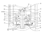
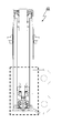
- FIG. 6A is a cross-sectional view of the hydraulic shock absorber 45 according to the second embodiment
- FIG. 6B is an enlarged view of a portion enclosed by a dashed line a in FIG. 6A
- FIG. 6C is a portion enclosed by a dashed line b in FIG. FIG.
- the hydraulic shock absorber 45 shown in FIGS. 6A to 6C shows a state in which no load is generated and no load is generated.
- FIGS. 7A, 7B, and 7C are diagrams showing an operation state when the hydraulic shock absorber 45 according to the second embodiment shown in FIGS. 6A to 6C is compressed and a load starts to be applied, respectively. The state of the part corresponding to Drawing 6B and Drawing 6C is shown.
- FIGS. 8A, 8B, and 8C are diagrams showing an operation state when compression to the hydraulic shock absorber 45 according to the second embodiment is continued and a high load state is obtained, and FIGS. 6A, 6B, and 6C, respectively. The state of the part corresponding to FIG. 6C is shown.
- FIGS. 9A, 9B, and 9C are diagrams showing an operating state when the piston rod enters the maximum stroke in compression to the hydraulic shock absorber 45 according to the second embodiment, and FIGS. 6A, 6B, and 6C, respectively. The state of the part corresponding to FIG. 6C is shown.
- FIGS. 9A to 9C only the parts necessary for the description of the operation are shown with the same reference numerals as in FIG. 6A, FIG. 6B or FIG. 6C.
- the upper end of the second spiral spring 23 which does not engage with other members in the unloaded state is an unstable free end, and the free length of this spring is When the outer diameter is long and the gap with the cylinder inner wall is small, there is a possibility that the cylinder inner wall may be damaged by sliding contact with the cylinder inner wall to generate minute noise.
- a second spiral spring guide 29 engaged with the upper end portion of the second spiral spring 23 is provided.
- the second spiral spring guide 29 has an annular shape, low aggression when touching the cylinder inner wall, and a member such as resin that can withstand wear by itself, and the outer circumferential portion can slide up and down the cylinder inner wall It is configured.
- a small diameter annular portion protrudes downward from a lower portion of the second helical spring guide 29, and an upper end portion of the second helical spring 23 is engaged with an outer periphery of the small diameter annular portion.
- the second compression side port 32 shown in FIGS. 2A to 5C is omitted.
- a third valve 51 is provided at the inner bottom of the first valve 24.
- the third valve 51 has a funnel-shaped sub-valve cup 52, and the funnel-shaped upper portion surrounds the step between the lower end of the large diameter cylindrical portion 34a of the base bolt 34 and the small diameter cylindrical portion 34b, Extends downward through the bottom of the first valve 24 to the central portion of the small diameter cylindrical portion 34 b of the base bolt 34.
- the third valve 51 is sandwiched between the base valve 27 and the base bolt 34 and fixed by screwing the base nut 35.
- the first valve 24 is held on the upper side by the first helical spring 28 so as to be slidable up and down in the outer diameter portion of the sub valve cup 52.
- a small diameter disc valve valve 46 having a diameter slightly smaller than that of the disc valve valve 17 is disposed on the funnel-shaped upper portion of the sub valve cup 52 of the third valve 51.
- the small diameter disc type valve valve 46 has a central hole, which is fitted to the outer peripheral surface of the small diameter cylindrical portion 34 b of the base bolt 34.
- the small diameter disc type valve valve 46 has the upper surface around the central hole held on one side by the sub valve plate 53 and on the other side pressed against the lower opening of the third compression port 50.
- the configuration and function of each part other than the above are the same as those in FIGS. 2A to 5C.
- the piston rod 11 starts to push the second helical spring 23 through the second helical spring guide 29.
- the piston rod 11 further depresses the second helical spring 23, a repulsive force is generated in the second helical spring 23, and a load is generated in the hydraulic shock absorber 45.
- the above-mentioned repulsive force is a downward biasing force on the first valve 24, and pushes the first valve 24 downward against the push-up biasing force of the first helical spring 28.
- the first compression port 31 is closed, and the flow of oil from the first compression port 31 shown in FIG. 6C is shut off.
- the first new flow path g indicated by a broken line arrow in FIG. 7C of the oil in the cylinder 12 is the small diameter of the first valve 24, the third compression port 50, the small diameter disc type valve valve 46, and the base bolt 34.
- a communication hole to the cylindrical portion 34 b, the inside of the small diameter cylindrical portion 34 b, and the space 42 formed between the bottom stopper 26 and the base valve 27 are formed.
- the flow velocity of the oil from the cylinder 12 to the reservoir chamber 15 is adjusted to decrease, and the rise in differential pressure between the lower oil chamber 21b and the reservoir chamber 15 is suppressed
- the resistance to the piston rod 11 is reduced, and the damping force of the hydraulic shock absorber 45 is reduced.
- the piston rod 11 further advances into the cylinder 12 and the hydraulic shock absorber 45 is in a high load state, and the internal pressure of the cylinder 12 (lower oil chamber 21b When the internal pressure) exceeds a predetermined pressure, the pressure pushes the valve washer 37 of the second valve 33 against the push-up biasing force of the third helical spring 38.
- the closure of the central hole 39 of the cap washer 36 is released, and the second new flow passage h indicated by the dashed arrow of the fluid in the cylinder 12 is the side of the central hole 39 of the cap washer 36 and the valve washer 37.
- the small diameter cylindrical portion 34b is formed to merge with the first new flow path g described above.
- the second newly formed flow passage h is adjusted to decrease the flow velocity of the oil from the cylinder 12 to the reservoir chamber 15 in combination with the first new flow passage g.
- An increase in differential pressure between the lower oil chamber 21b and the reservoir chamber 15 can be suppressed. Also, this can prevent damage to the internal parts.
- the damping characteristics can be easily changed by changing the number, thickness, outer diameter and the like of the small diameter disc type valve valves sandwiched between the sub valve cup and the sub valve plate. Furthermore, by changing the free length of the second helical spring, it is possible to easily change the position at which the first compression port is closed and the operating point.
- the flow path of the fluid in which the cylinder 12 (the lower oil chamber 21b) and the reservoir chamber 15 communicate with each other is maintained only by the first new flow path g indicated by the broken arrow. Also at this maximum stroke, when the pressure in the cylinder 12 is not equal to or higher than the predetermined pressure, there is no difference from the “load start state” shown in FIGS. 7A to 7C.
- FIG. 10A is a cross-sectional view of a hydraulic shock absorber 60 according to a third embodiment in which the configurations of the first and second embodiments are combined
- FIG. 10B is an enlarged view of a portion enclosed by a dotted line a in FIG. Is a magnified view of a portion surrounded by a dashed line b of FIG.
- the third embodiment is configured of the second compression side port 32 of the first embodiment and the third valve 51 of the second embodiment, and the operation when the first valve 24 closes the first compression side port is the embodiment. It becomes what combined 1 and Example 2.
- the present invention is applicable to a hydraulic shock absorber.
Landscapes
- Engineering & Computer Science (AREA)
- General Engineering & Computer Science (AREA)
- Mechanical Engineering (AREA)
- Physics & Mathematics (AREA)
- Fluid Mechanics (AREA)
- Fluid-Damping Devices (AREA)
Abstract
Description
[実施例1]
[実施例2]
[実施例3]
2 アッパースプリングシート
3 ピストンロッド
4 油室
4a 上方油室
4b 下方油室
5 シリンダ
6 ピストンバルブ
7 外筒
8 バンプストッパ
9 バンプストップラバー
10 油圧緩衝器
11 ピストンロッド
12 シリンダ
13 外筒
14 車軸保持係合部
15 リザーバ室
16 バンプストッパ
17(17a、17b、17c) ディスク型バルブ弁
18 フランジ状封止部材
19 円環状封止部材
21(21a、21b) 油室
22 ピストンバルブ
23 第2螺旋ばね
24 第1バルブ
25 フランジ
26 ボトムストッパ
27 ベースバルブ
28 第1螺旋ばね
29 第2螺旋ばねガイド
31 第1圧縮側ポート
32 第2圧縮側ポート
33 第2バルブ
34 ベースボルト
34a 大径円筒部
34b 小径円筒部
35 ベースナット
36 キャプワッシャ
37 バルブワッシャ
38 第3螺旋ばね
39 中央孔
41 側方孔
42 空間
45 油圧緩衝器
46 小径ディスク型バルブ弁
50 第3圧縮ポート
51 第3バルブ
52 サブバルブカップ
53 サブバルブプレート
60 油圧緩衝器
Claims (3)
- シリンダと、
該シリンダ内を満たして封入され、該シリンダ内に油室を形成する油液と、
前記油室を進退するピストンロッドと、
該ピストンロッドの先端に固定され、前記油室を上部と下部の油室に区画しつつ、前記ピストンロッドの進退に伴われて前記シリンダの内周に摺接して進退するピストンバルブと、
前記シリンダの外周を覆う外筒と、
該外筒の内周面と前記シリンダの外周面との間隙から成り、油液とガスが封入されたリザーバ室と、
前記外筒の底部を外部から封止するボトムストッパと、
該ボトムストッパに保持され、前記下部の油室と前記リザーバ室とを連通させる第1圧縮側ポートと第2圧縮側ポートを有するベースバルブと、
該ベースバルブに第1螺旋ばねを介して保持される第1バルブと、
該第1バルブに保持され、該第1バルブと前記ピストンバルブとの間に介装され、前記ピストンバルブに押圧されると下方に反発力を発生させ、前記第1螺旋ばねの付勢力に抗して前記第1バルブを押し下げて前記第1圧縮側ポートを閉鎖させる第2螺旋ばねと、
前記第1バルブ及び前記ベースバルブの中央を貫通して配設され、外部からの負荷により前記シリンダの前記下部の油室の圧力が所定以上になると前記リザーバ室との間の前記油液の流量を調整する第2バルブと、
を備えることを特徴とする油圧緩衝器。 - シリンダと、
該シリンダ内を満たして封入され、該シリンダ内に油室を形成する油液と、
前記油室を進退するピストンロッドと、
該ピストンロッドの先端に固定され、前記油室を上部と下部の油室に区画しつつ、前記ピストンロッドの進退に伴われて前記シリンダの内周に摺接して進退するピストンバルブと、
前記シリンダの外周を覆う外筒と、
該外筒の内周面と前記シリンダの外周面との間隙から成り、油液とガスが封入されたリザーバ室と、
前記外筒の底部を外部から封止するボトムストッパと、
該ボトムストッパに保持され、前記下部の油室と前記リザーバ室とを連通させる第1圧縮側ポートを有するベースバルブと、
該ベースバルブに第1螺旋ばねを介して保持される第1バルブと、
該第1バルブに保持され、該第1バルブと前記ピストンバルブとの間に介装され、前記ピストンバルブに押圧されると下方に反発力を発生させ、前記第1螺旋ばねの付勢力に抗して前記第1バルブを押し下げて前記第1圧縮側ポートを閉鎖させる第2螺旋ばねと、
前記第1バルブ及び前記ベースバルブの中央を貫通して配設され、外部からの負荷により前記シリンダの前記下部の油室の圧力が所定以上になると前記リザーバ室との間の前記油液の流量を調整する第2バルブと、
前記第1バルブの底部に配設され、該第1バルブの前記第2バルブが貫通する被貫通孔と前記第2バルブの外周との間に挟持され、前記第2バルブによる前記油液の流量の調整に先立って、前記シリンダの前記下部の油室の所定の圧力に応じて前記リザーバ室との間の前記油液の流量を調整する第3バルブと、
を備えることを特徴とする油圧緩衝器。 - 請求項2の構成に請求項1の第2圧縮側ポートを有するベースバルブを備えることを特徴とする油圧緩衝器。
Priority Applications (11)
| Application Number | Priority Date | Filing Date | Title |
|---|---|---|---|
| JP2015534225A JP6277447B2 (ja) | 2013-08-26 | 2014-08-26 | 油圧緩衝器 |
| US14/911,163 US10195918B2 (en) | 2013-08-26 | 2014-08-26 | Hydraulic damper |
| EP14841233.1A EP3040577B1 (en) | 2013-08-26 | 2014-08-26 | Hydraulic shock-absorbing device |
| PL14841233T PL3040577T3 (pl) | 2013-08-26 | 2014-08-26 | Hydrauliczne urządzenie amortyzujące |
| RU2016105510A RU2628552C1 (ru) | 2013-08-26 | 2014-08-26 | Гидравлический демпфер |
| ES14841233T ES2741287T3 (es) | 2013-08-26 | 2014-08-26 | Dispositivo de parachoques hidráulico |
| DK14841233.1T DK3040577T3 (da) | 2013-08-26 | 2014-08-26 | Hydraulisk støddæmper |
| AU2014312958A AU2014312958B2 (en) | 2013-08-26 | 2014-08-26 | Hydraulic shock-absorbing device |
| CN201480046554.3A CN105593565B (zh) | 2013-08-26 | 2014-08-26 | 液压缓冲器 |
| HK16112151.2A HK1223997A1 (zh) | 2013-08-26 | 2016-10-21 | 液壓緩衝器 |
| CY20191100799T CY1121836T1 (el) | 2013-08-26 | 2019-07-26 | Υδραυλικη διαταξη αποσβεσης κραδασμων |
Applications Claiming Priority (2)
| Application Number | Priority Date | Filing Date | Title |
|---|---|---|---|
| JP2013174397 | 2013-08-26 | ||
| JP2013-174397 | 2013-08-26 |
Publications (1)
| Publication Number | Publication Date |
|---|---|
| WO2015029984A1 true WO2015029984A1 (ja) | 2015-03-05 |
Family
ID=52586541
Family Applications (1)
| Application Number | Title | Priority Date | Filing Date |
|---|---|---|---|
| PCT/JP2014/072262 WO2015029984A1 (ja) | 2013-08-26 | 2014-08-26 | 油圧緩衝器 |
Country Status (13)
| Country | Link |
|---|---|
| US (1) | US10195918B2 (ja) |
| EP (1) | EP3040577B1 (ja) |
| JP (1) | JP6277447B2 (ja) |
| CN (1) | CN105593565B (ja) |
| AU (1) | AU2014312958B2 (ja) |
| CY (1) | CY1121836T1 (ja) |
| DK (1) | DK3040577T3 (ja) |
| ES (1) | ES2741287T3 (ja) |
| HK (1) | HK1223997A1 (ja) |
| PL (1) | PL3040577T3 (ja) |
| PT (1) | PT3040577T (ja) |
| RU (1) | RU2628552C1 (ja) |
| WO (1) | WO2015029984A1 (ja) |
Cited By (3)
| Publication number | Priority date | Publication date | Assignee | Title |
|---|---|---|---|---|
| CN108778789A (zh) * | 2016-03-25 | 2018-11-09 | 标致雪铁龙汽车股份有限公司 | 车辆的液压悬架系统 |
| CN108883680A (zh) * | 2016-03-25 | 2018-11-23 | 标致雪铁龙汽车股份有限公司 | 车辆的液压悬架系统 |
| CN108883679A (zh) * | 2016-03-25 | 2018-11-23 | 标致雪铁龙汽车股份有限公司 | 车辆的液压悬架系统 |
Families Citing this family (5)
| Publication number | Priority date | Publication date | Assignee | Title |
|---|---|---|---|---|
| US9964171B2 (en) | 2014-10-01 | 2018-05-08 | Beijingwest Industries Co., Ltd. | Damper assembly |
| FR3049225B1 (fr) * | 2016-03-25 | 2018-04-13 | Peugeot Citroen Automobiles Sa | Systeme de suspension hydraulique d’un vehicule |
| JP6826487B2 (ja) * | 2017-04-25 | 2021-02-03 | Kybモーターサイクルサスペンション株式会社 | フロントフォーク |
| WO2020231972A1 (en) | 2019-05-13 | 2020-11-19 | Tenneco Automotive Operating Company Inc. | Hydraulic compression stop with biased piston |
| US10962081B2 (en) | 2019-09-16 | 2021-03-30 | Tenneco Automotive Operating Company Inc. | Damper with dual springs |
Citations (4)
| Publication number | Priority date | Publication date | Assignee | Title |
|---|---|---|---|---|
| US2742112A (en) * | 1951-07-05 | 1956-04-17 | Houdaille Hershey Corp | Telescopic shock absorber construction |
| US4768629A (en) * | 1985-09-19 | 1988-09-06 | Fichtel & Sachs Ag | Double-tube vibration damper |
| JP2005299786A (ja) | 2004-04-12 | 2005-10-27 | Kayaba Ind Co Ltd | クッション装置 |
| JP2012503751A (ja) * | 2008-09-26 | 2012-02-09 | テネコ オートモティブ オペレーティング カンパニー インコーポレイテッド | 高速圧縮減衰バルブ |
Family Cites Families (12)
| Publication number | Priority date | Publication date | Assignee | Title |
|---|---|---|---|---|
| US2619199A (en) * | 1950-10-14 | 1952-11-25 | Gabriel Co | Shock absorber |
| JPS412171Y1 (ja) * | 1964-10-29 | 1966-02-15 | ||
| US4782925A (en) * | 1986-01-25 | 1988-11-08 | Fichtel & Sachs Ag | Double-tube vibration damper |
| US5333708A (en) * | 1993-01-11 | 1994-08-02 | General Motors Corporation | Compression cut-off valve for a hydraulic damper |
| US5462143A (en) * | 1993-02-17 | 1995-10-31 | August Bilstein Gmbh & Co. Kg | Controllable shock absorber for motor vehicles |
| DE102006010245A1 (de) * | 2006-03-02 | 2007-09-06 | Gustav Magenwirth Gmbh & Co. Kg | Federwegsverstellung |
| DE102006040678A1 (de) * | 2006-08-30 | 2008-03-20 | Tecpharma Licensing Ag | Vorrichtung zur Verabreichung eines fluiden Produkts |
| CN201027894Y (zh) * | 2007-04-30 | 2008-02-27 | 东风汽车公司 | 液压限位减振器 |
| US9285011B2 (en) | 2008-09-26 | 2016-03-15 | Tenneco Automotive Operating Company Inc. | High velocity compression damping valve |
| SE533996C2 (sv) * | 2009-04-23 | 2011-03-22 | Oehlins Racing Ab | Tryckregulator i en stötdämparventil |
| JP5418778B2 (ja) * | 2010-02-26 | 2014-02-19 | 日立オートモティブシステムズ株式会社 | 緩衝器 |
| RU2494295C1 (ru) * | 2012-04-03 | 2013-09-27 | Олег Савдаханович Гильмханов | Гидравлический телескопический амортизатор |
-
2014
- 2014-08-26 PL PL14841233T patent/PL3040577T3/pl unknown
- 2014-08-26 CN CN201480046554.3A patent/CN105593565B/zh active Active
- 2014-08-26 EP EP14841233.1A patent/EP3040577B1/en active Active
- 2014-08-26 RU RU2016105510A patent/RU2628552C1/ru active
- 2014-08-26 JP JP2015534225A patent/JP6277447B2/ja active Active
- 2014-08-26 PT PT14841233T patent/PT3040577T/pt unknown
- 2014-08-26 AU AU2014312958A patent/AU2014312958B2/en active Active
- 2014-08-26 ES ES14841233T patent/ES2741287T3/es active Active
- 2014-08-26 US US14/911,163 patent/US10195918B2/en active Active
- 2014-08-26 DK DK14841233.1T patent/DK3040577T3/da active
- 2014-08-26 WO PCT/JP2014/072262 patent/WO2015029984A1/ja active Application Filing
-
2016
- 2016-10-21 HK HK16112151.2A patent/HK1223997A1/zh unknown
-
2019
- 2019-07-26 CY CY20191100799T patent/CY1121836T1/el unknown
Patent Citations (4)
| Publication number | Priority date | Publication date | Assignee | Title |
|---|---|---|---|---|
| US2742112A (en) * | 1951-07-05 | 1956-04-17 | Houdaille Hershey Corp | Telescopic shock absorber construction |
| US4768629A (en) * | 1985-09-19 | 1988-09-06 | Fichtel & Sachs Ag | Double-tube vibration damper |
| JP2005299786A (ja) | 2004-04-12 | 2005-10-27 | Kayaba Ind Co Ltd | クッション装置 |
| JP2012503751A (ja) * | 2008-09-26 | 2012-02-09 | テネコ オートモティブ オペレーティング カンパニー インコーポレイテッド | 高速圧縮減衰バルブ |
Cited By (4)
| Publication number | Priority date | Publication date | Assignee | Title |
|---|---|---|---|---|
| CN108778789A (zh) * | 2016-03-25 | 2018-11-09 | 标致雪铁龙汽车股份有限公司 | 车辆的液压悬架系统 |
| CN108883680A (zh) * | 2016-03-25 | 2018-11-23 | 标致雪铁龙汽车股份有限公司 | 车辆的液压悬架系统 |
| CN108883679A (zh) * | 2016-03-25 | 2018-11-23 | 标致雪铁龙汽车股份有限公司 | 车辆的液压悬架系统 |
| CN108883680B (zh) * | 2016-03-25 | 2022-04-15 | 标致雪铁龙汽车股份有限公司 | 车辆的液压悬架系统 |
Also Published As
| Publication number | Publication date |
|---|---|
| EP3040577A1 (en) | 2016-07-06 |
| JPWO2015029984A1 (ja) | 2017-03-02 |
| US10195918B2 (en) | 2019-02-05 |
| PT3040577T (pt) | 2019-08-19 |
| PL3040577T3 (pl) | 2019-12-31 |
| US20160185181A1 (en) | 2016-06-30 |
| AU2014312958B2 (en) | 2016-10-20 |
| CN105593565A (zh) | 2016-05-18 |
| ES2741287T3 (es) | 2020-02-10 |
| JP6277447B2 (ja) | 2018-02-14 |
| CY1121836T1 (el) | 2020-07-31 |
| AU2014312958A1 (en) | 2016-03-03 |
| CN105593565B (zh) | 2017-10-03 |
| HK1223997A1 (zh) | 2017-08-11 |
| EP3040577A4 (en) | 2017-05-10 |
| DK3040577T3 (da) | 2019-08-26 |
| EP3040577B1 (en) | 2019-06-05 |
| RU2628552C1 (ru) | 2017-08-18 |
Similar Documents
| Publication | Publication Date | Title |
|---|---|---|
| WO2015029984A1 (ja) | 油圧緩衝器 | |
| JP5008667B2 (ja) | 非対称吸込減衰弁 | |
| US5810130A (en) | Suspension damper with rebound cut-off | |
| KR101375804B1 (ko) | 주파수 및 압력 감응형 쇽업소버 | |
| JP4890272B2 (ja) | 気体式のショックアブソーバのロッドガイド及びシールシステム | |
| US20030051957A1 (en) | Shock absorber with a floating piston | |
| US8641022B2 (en) | Front fork | |
| WO2017175784A1 (ja) | 緩衝器 | |
| JP2017003017A (ja) | 緩衝器 | |
| JP5851159B2 (ja) | 緩衝器 | |
| US10837514B2 (en) | Valve structure of shock absorber | |
| JP2015197141A (ja) | 緩衝器 | |
| JP5136780B2 (ja) | 流体圧緩衝器 | |
| US11339848B2 (en) | Shock absorber with a hydrostopper | |
| JP2007092926A (ja) | ショックアブソーバ | |
| CN109983250B (zh) | 减震器 | |
| KR101901446B1 (ko) | 쇽업소버의 피스톤 밸브 | |
| JP6496197B2 (ja) | 緩衝器 | |
| JP2016080140A (ja) | 圧力緩衝装置 | |
| JP7154199B2 (ja) | 緩衝器 | |
| JP2020016287A (ja) | シリンダ装置 | |
| JP6246425B1 (ja) | 緩衝器 | |
| JP2012530882A (ja) | 油圧ダンパ及び油圧ダンパ用ピストンヘッド組立体 | |
| WO2020261941A1 (ja) | シリンダ装置 | |
| JP2023004734A (ja) | 緩衝器 |
Legal Events
| Date | Code | Title | Description |
|---|---|---|---|
| 121 | Ep: the epo has been informed by wipo that ep was designated in this application |
Ref document number: 14841233 Country of ref document: EP Kind code of ref document: A1 |
|
| ENP | Entry into the national phase |
Ref document number: 2015534225 Country of ref document: JP Kind code of ref document: A |
|
| REEP | Request for entry into the european phase |
Ref document number: 2014841233 Country of ref document: EP |
|
| WWE | Wipo information: entry into national phase |
Ref document number: 2014841233 Country of ref document: EP |
|
| WWE | Wipo information: entry into national phase |
Ref document number: 14911163 Country of ref document: US |
|
| NENP | Non-entry into the national phase |
Ref country code: DE |
|
| ENP | Entry into the national phase |
Ref document number: 2014312958 Country of ref document: AU Date of ref document: 20140826 Kind code of ref document: A |
|
| ENP | Entry into the national phase |
Ref document number: 2016105510 Country of ref document: RU Kind code of ref document: A |