WO2015029466A1 - レーザ加工装置 - Google Patents
レーザ加工装置 Download PDFInfo
- Publication number
- WO2015029466A1 WO2015029466A1 PCT/JP2014/054735 JP2014054735W WO2015029466A1 WO 2015029466 A1 WO2015029466 A1 WO 2015029466A1 JP 2014054735 W JP2014054735 W JP 2014054735W WO 2015029466 A1 WO2015029466 A1 WO 2015029466A1
- Authority
- WO
- WIPO (PCT)
- Prior art keywords
- laser
- wavelength
- irradiation head
- workpiece
- processing apparatus
- Prior art date
Links
Images


Classifications
-
- B—PERFORMING OPERATIONS; TRANSPORTING
- B23—MACHINE TOOLS; METAL-WORKING NOT OTHERWISE PROVIDED FOR
- B23K—SOLDERING OR UNSOLDERING; WELDING; CLADDING OR PLATING BY SOLDERING OR WELDING; CUTTING BY APPLYING HEAT LOCALLY, e.g. FLAME CUTTING; WORKING BY LASER BEAM
- B23K26/00—Working by laser beam, e.g. welding, cutting or boring
- B23K26/02—Positioning or observing the workpiece, e.g. with respect to the point of impact; Aligning, aiming or focusing the laser beam
- B23K26/06—Shaping the laser beam, e.g. by masks or multi-focusing
- B23K26/0604—Shaping the laser beam, e.g. by masks or multi-focusing by a combination of beams
- B23K26/0613—Shaping the laser beam, e.g. by masks or multi-focusing by a combination of beams having a common axis
- B23K26/0617—Shaping the laser beam, e.g. by masks or multi-focusing by a combination of beams having a common axis and with spots spaced along the common axis
-
- B—PERFORMING OPERATIONS; TRANSPORTING
- B23—MACHINE TOOLS; METAL-WORKING NOT OTHERWISE PROVIDED FOR
- B23K—SOLDERING OR UNSOLDERING; WELDING; CLADDING OR PLATING BY SOLDERING OR WELDING; CUTTING BY APPLYING HEAT LOCALLY, e.g. FLAME CUTTING; WORKING BY LASER BEAM
- B23K26/00—Working by laser beam, e.g. welding, cutting or boring
- B23K26/02—Positioning or observing the workpiece, e.g. with respect to the point of impact; Aligning, aiming or focusing the laser beam
- B23K26/06—Shaping the laser beam, e.g. by masks or multi-focusing
- B23K26/064—Shaping the laser beam, e.g. by masks or multi-focusing by means of optical elements, e.g. lenses, mirrors or prisms
- B23K26/0648—Shaping the laser beam, e.g. by masks or multi-focusing by means of optical elements, e.g. lenses, mirrors or prisms comprising lenses
-
- B—PERFORMING OPERATIONS; TRANSPORTING
- B23—MACHINE TOOLS; METAL-WORKING NOT OTHERWISE PROVIDED FOR
- B23K—SOLDERING OR UNSOLDERING; WELDING; CLADDING OR PLATING BY SOLDERING OR WELDING; CUTTING BY APPLYING HEAT LOCALLY, e.g. FLAME CUTTING; WORKING BY LASER BEAM
- B23K26/00—Working by laser beam, e.g. welding, cutting or boring
- B23K26/352—Working by laser beam, e.g. welding, cutting or boring for surface treatment
- B23K26/356—Working by laser beam, e.g. welding, cutting or boring for surface treatment by shock processing
-
- B—PERFORMING OPERATIONS; TRANSPORTING
- B23—MACHINE TOOLS; METAL-WORKING NOT OTHERWISE PROVIDED FOR
- B23K—SOLDERING OR UNSOLDERING; WELDING; CLADDING OR PLATING BY SOLDERING OR WELDING; CUTTING BY APPLYING HEAT LOCALLY, e.g. FLAME CUTTING; WORKING BY LASER BEAM
- B23K26/00—Working by laser beam, e.g. welding, cutting or boring
- B23K26/36—Removing material
- B23K26/38—Removing material by boring or cutting
Definitions
- the present invention relates to a laser processing apparatus that performs processing by irradiating a member to be processed with a laser.
- Patent Documents 1 to 3 Conventionally, processing using a long-wavelength laser capable of condensing light at a high density in a small spot and a short-wavelength laser having a high absorbability to metal is disclosed in Patent Documents 1 to 3, for example. It is shown.
- JP-A 63-295093 JP 2001-196665 A Japanese Patent Laid-Open No. 2006-267371
- Patent Documents 1 to 3 The laser processing apparatuses described in Patent Documents 1 to 3 described above generate lasers having different wavelength bands from different oscillation sources. For this reason, there is a concern about an increase in the size of the apparatus.
- Patent Document 1 since lasers having different wavelength bands are separately irradiated onto members to be processed, separate optical systems, processing heads, moving mechanisms, and the like are required, which increases the number of components and makes the apparatus configuration complicated. The device becomes larger.
- patent document 2 and patent document 3 since the lasers with different wavelength bands are superimposed and condensed on the same optical axis, the optical system for superimposing becomes complicated.
- the present invention solves the above-described problems, and an object of the present invention is to provide a laser processing apparatus capable of simplifying the configuration even when lasers having different wavelength bands are used.
- a laser processing apparatus of the present invention condenses a laser output device that oscillates a laser having a plurality of wavelength bands and a laser of each wavelength band by shifting the focal length on the same optical axis. And an irradiation head for irradiation.
- this laser processing apparatus by providing a laser output device that oscillates a laser having a plurality of wavelength bands, it is possible to oscillate a laser having a plurality of wavelength bands without increasing the size of the apparatus.
- an irradiation head for condensing and irradiating lasers of each wavelength band on the same optical axis at different focal lengths the wavelength band for processing and the wavelength band for assisting the processing are on the same optical axis. Can be performed simultaneously in a series of processing operations. As a result, the configuration can be simplified even when lasers having different wavelength bands are used.
- the irradiation head focuses a laser having a short wavelength in the focus of the long wavelength laser so that a focal position of the laser having a long wavelength is aligned with a processing position. It is characterized by.
- the focus of a long wavelength laser that can be condensed at high density is adjusted to the processing position, and the short wavelength laser having a high absorption rate is focused inside the focus of the long wavelength laser.
- the workpiece is preheated with a short wavelength laser on the outer periphery, and the preheated workpiece is processed with a long wavelength laser.
- the processing speed and processing quality can be improved by performing preheating with processing.
- the irradiation head focuses a laser having a long wavelength with the focal point of the laser having a short wavelength inside the focus position of the laser having a short wavelength aligned with a processing position. It is characterized by.
- this laser processing apparatus by disposing the focal point of the short wavelength laser in the focusing of the long wavelength laser having a relatively high power density, the workpiece is melted and processed by the short wavelength laser. Since the temperature of the metal melted by radiation from the plasma generated by melting the workpiece is raised by a long wavelength laser to reduce the viscosity, the machining quality can be improved.
- the laser processing apparatus of the present invention is characterized by having a focal length adjusting device including a concave glass and a convex glass, each movable in the optical axis direction.
- the focal point can be easily aligned with the processing position by changing the focal length of each laser having a different wavelength band by the focal length adjusting device.
- a moving mechanism that relatively moves the support base that supports the workpiece and the irradiation head, a relative movement between the support base and the irradiation head by the moving mechanism, and a laser output device And a control device for adjusting various conditions of the laser output from.
- the configuration can be simplified even when lasers having different wavelength bands are used by adjusting the relative movement between the support base and the irradiation head by the moving mechanism and various conditions of the laser output from the laser output apparatus. Meanwhile, the workpiece can be processed by the laser.
- the configuration can be simplified even when lasers having different wavelength bands are used.
- FIG. 1 is a schematic configuration diagram schematically showing a laser processing apparatus according to an embodiment of the present invention.
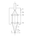
- FIG. 2 is a schematic configuration diagram schematically showing an irradiation head of the laser processing apparatus according to the first embodiment of the present invention.
- FIG. 3 is an enlarged plan view of the laser irradiated from the irradiation head shown in FIG.
- FIG. 4 is a diagram showing the relationship between the laser wavelength and the absorptance of the workpiece.
- FIG. 5 is a schematic configuration diagram schematically showing another irradiation head of the laser processing apparatus according to the first embodiment of the present invention.
- FIG. 6 is a schematic configuration diagram schematically showing an irradiation head of the laser processing apparatus according to the second embodiment of the present invention.
- FIG. 7 is an enlarged plan view of the laser irradiated from the irradiation head shown in FIG.
- this invention is not limited by this embodiment.
- this embodiment demonstrates as a case where a plate-shaped workpiece is processed, the shape of a workpiece is not specifically limited.
- the shape of the workpiece can be various shapes.
- a case where a hole is formed in a workpiece a case where the workpiece is cut on a straight line, or a case where the workpiece is welded will be described, but the machining position on the workpiece, that is, By adjusting the laser irradiation position, a shape other than a hole or a straight line, for example, a shape having a bending point or a curved shape can be obtained.
- the laser beam and the workpiece are moved relatively by moving the workpiece.
- the laser may be moved, and both the laser and the workpiece are moved. You may let them.
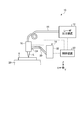
- FIG. 1 is a schematic configuration diagram schematically showing a laser processing apparatus according to the present embodiment.
- the laser processing apparatus 10 includes a laser output device 12, a guide optical system 14, an irradiation head 16, a moving mechanism 18, a support base 20, and a control device 22.
- the laser processing apparatus 10 processes the workpiece 8 by irradiating the workpiece L installed on the support base 20 with the laser L.
- the laser processing apparatus 10 sets the surface of the member 8 to be processed as an XY plane and the direction orthogonal to the surface of the member 8 as a Z direction.
- the workpiece 8 of the present embodiment is a plate-like member.
- a member made of various materials for example, Inconel, Hastelloy, stainless steel, ceramic, steel, carbon steel, ceramics, silicon, titanium, tungsten, resin, plastics, glass or the like is used. it can.
- the workpiece 8 includes fiber reinforced plastics such as CFRP (carbon fiber reinforced plastic, Carbon Fiber Reinforced Plastics), GFRP (glass fiber reinforced plastic), GMT (glass long fiber reinforced plastic), iron alloys other than steel plates, Members made of various metals such as aluminum alloys and other composite materials can also be used.
- CFRP carbon fiber reinforced plastic, Carbon Fiber Reinforced Plastics
- GFRP glass fiber reinforced plastic
- GMT glass long fiber reinforced plastic
- iron alloys other than steel plates Members made of various metals such as aluminum alloys and other composite materials can also be used.
- the laser output device 12 is a device that outputs a laser.
- the laser output device 12 oscillates a laser having a plurality of wavelength bands.
- An example of the laser output device 12 is a semiconductor laser oscillator.
- the guide optical system 14 is an optical system that guides the laser output from the laser output device 12 to the irradiation head 16.
- the guide optical system 14 of this embodiment is an optical fiber.
- the guide optical system 14 has one end connected to the laser emission port of the laser output device 12 and the other end connected to the irradiation head 16.
- the guide optical system 14 outputs the laser output from the laser output device 12 toward the incident end of the irradiation head 16.
- the configuration of the guide optical system 14 is not limited to this.
- the laser processing apparatus 10 may guide the irradiation head 16 by using a combination of a mirror and a lens as the guide optical system 14 and reflecting or condensing the laser. Or you may guide directly to the irradiation head 16 from the laser output apparatus 12.
- the irradiation head 16 irradiates the workpiece 8 with the laser L output from the guide optical system 14. Details of the irradiation head 16 will be described later.
- the moving mechanism 18 includes an arm 30 and a drive source 32 that moves the arm 30.
- the arm 30 supports the irradiation head 16 at the tip.
- the drive source 32 can move the arm 30 in the three-axis directions of XYZ.
- the moving mechanism 18 can irradiate the laser L from the irradiation head 16 to various positions of the workpiece 8 by moving the arm 30 in the XYZ directions by the drive source 32.
- the moving mechanism 18 has a position detector 34 that detects the position of the irradiation head 16 in the XYZ directions.
- the moving mechanism 18 is a mechanism that moves the irradiation head 16 using the arm 30 and the drive source 32.
- a mechanism that moves the irradiation head 16 using an XY stage, an XYZ stage, or the like can also be used.
- the support base 20 supports the workpiece 8 at a predetermined position.
- the support base 20 may be configured as an XY stage that moves the workpiece 8 in the XY direction.
- Control device 22 controls the operation of each unit.
- the control device 22 adjusts various conditions of the laser output from the laser output device 12 or moves the irradiation head 16 by the moving mechanism 18 to adjust the position of the irradiation head 16 with respect to the workpiece 8.
- the laser processing apparatus 10 outputs a laser from the laser output apparatus 12.
- the laser processing apparatus 10 guides the output laser L to the irradiation head 16 by the guide optical system 14.
- the laser processing apparatus 10 moves the irradiation head 16 by the moving mechanism 18 while detecting the position of the irradiation head 16 in the XYZ directions by the position detector 34. Thereby, the laser processing apparatus 10 can process the workpiece 8.
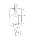
- FIG. 2 is a schematic configuration diagram schematically showing an irradiation head of the laser processing apparatus according to the present embodiment
- FIG. 3 shows an optical axis direction of the laser irradiated to the workpiece from the irradiation head shown in FIG.
- FIG. 4 is an enlarged plan view as seen in the direction along the extending direction of the optical axis
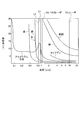
- FIG. 4 is a diagram showing the relationship between the wavelength of the laser and the absorptance of the workpiece.
- the irradiation head 16 includes a parallel optical system 16 b that converts the laser beam incident from the guide optical system 14 into parallel light inside the casing 16 a supported by the moving mechanism 18 described above, and a parallel optical system.
- a condensing optical system 16c that condenses the laser beam collimated by 16b on the optical axis S is provided. Note that the parallel optical system 16b and the condensing optical system 16c shown in FIG. 2 are schematic, and the lens configuration is not limited.
- the focused laser L is irradiated to the workpiece 8.
- the laser output device 12 oscillates a laser having a plurality of (two in FIG. 2) wavelength bands. This laser is converted into parallel light by the parallel optical system 16b and condensed by the condensing optical system 16c in the irradiation head 16, but the focal lengths of the lasers L1 and L2 of each wavelength band are shifted on the same optical axis S. Condensed and irradiated. In this embodiment, as shown in FIG. 2 and FIG.
- the focal position of the laser L1 having a long wavelength is matched with the processing position of the workpiece 8 (the surface of the workpiece 8), and the long wavelength laser L1
- the laser L2 having a short wavelength in the focal point is condensed. That is, the focus of the long wavelength laser L1 is focused on the processing position of the workpiece 8, and the laser L2 having a short wavelength is collected so as to surround the laser L1 around the focus of the long wavelength laser L1. Is done.
- the long wavelength laser L1 is capable of focusing on a small spot with high density, and the short wavelength laser L2 is highly absorbable to the workpiece 8. Therefore, the workpiece 8 is preheated by the outer peripheral short wavelength laser L2, and the preheated workpiece 8 is processed by the inner long wavelength laser L1. Therefore, by performing preheating with processing, the processing speed and processing quality can be improved.
- the semiconductor laser of this embodiment has a wavelength band of 808 nm and 940 nm.
- the absorptance of the aluminum alloy with respect to the laser wavelength is in the vicinity of 900 nm as shown in FIG.
- the wavelength band of 808 nm which has a high absorption rate
- the wavelength band of 940 nm is a long wavelength laser L1.
- a plurality of wavelength bands approximating the absorption wavelength of the workpiece 8 are used, and the higher wavelength is collected on the outer periphery with the higher absorption rate as the short wavelength side, and can be condensed at high density.
- a CO 2 laser generally used for laser processing has a wavelength of 106 ⁇ m
- an Nd: YAG laser neodymium yag laser
- the laser processing apparatus 10 of the present embodiment condenses and irradiates the laser output apparatus 12 that oscillates a laser having a plurality of wavelength bands and the lasers of each wavelength band on the same optical axis while shifting the focal length. And an irradiation head 16 for performing.
- this laser processing apparatus 10 by including the laser output device 12 that oscillates a laser having a plurality of wavelength bands, it is possible to oscillate a laser having a plurality of wavelength bands without increasing the size of the apparatus.
- the irradiation head 16 that condenses and irradiates lasers in the respective wavelength bands on the same optical axis S while shifting the focal length, the wavelength band for processing and the wavelength band for assisting the processing are the same light. Irradiation on the axis S allows machining and machining assistance to be performed simultaneously in a series of machining operations. As a result, the configuration can be simplified even when lasers having different wavelength bands are used.
- the irradiation head 16 aligns the focal position of the laser L1 having a long wavelength with the processing position, and the laser L2 having a short wavelength with the focal point of the long wavelength laser L1 in the middle. It is preferable to collect light.
- the focal point of a long wavelength laser L 1 that can be condensed at high density is aligned with the processing position of the workpiece 8, and the short wavelength laser L 2 having a high absorption rate is converted into a long wavelength laser.
- the workpiece 8 is preheated by the outer short wavelength laser L2, and the preheated workpiece 8 is processed by the long wavelength laser L1.
- the processing speed and processing quality can be improved by performing preheating with processing.
- the laser processing apparatus 10 of the present embodiment moves the irradiation head 16 by the moving mechanism 18 while detecting the position of the irradiation head 16 in the XYZ directions by the position detector 34.
- the focal position of the long wavelength laser L1 and the focal length of the short wavelength laser L2 are determined by the parallel optical system 16b and the condensing optical system 16c. Is stored in advance.
- the control device 22 moves the moving mechanism 18 so that the focus of the laser L (long-wavelength laser L1 in the present embodiment) is adjusted to the processing position of the processing member 8. The focus can be easily aligned with the processing position.
- FIG. 5 is a schematic configuration diagram schematically showing another irradiation head of the laser processing apparatus according to the present embodiment.
- the irradiation head 16 shown in FIG. 5 has a focal length adjustment device 17.
- the focal length adjusting device 17 includes, for example, a concave glass 17A and a convex glass 17B, and includes a glass moving mechanism 17C that enables the concave glass 17A and the convex glass 17B to move in the optical axis direction.
- the glass moving mechanism 17C is, for example, a support member 17Ca that supports the concave glass 17A and the convex glass 17B, and a guide that extends in the optical axis direction and moves each support member 17Ca in the optical axis direction.
- Guide rails 17Cb screw rods 17Cc that extend in the direction of the optical axis and are threadedly inserted into the support members 17Ca, and drive motors 17Cd that rotationally drive the screw rods 17Cc. That is, the glass moving mechanism 17C drives each drive motor 17Cd to rotate each screw rod 17Cc, so that each support member 17Ca is accompanied by the concave glass 17A and the convex glass 17B in the optical axis direction along the guide rail 17Cb. Moving. Thereby, the concave glass 17A and the convex glass 17B move in the optical axis direction, and the focal lengths of the lasers L1 and L2 having different wavelength bands are changed.
- the focal length adjusting device 17 is controlled by the control device 22.
- the moving distance between the concave glass 17A and the convex glass 17B, that is, the focal length is controlled in accordance with the rotational speed of the screw rod 17Cc by the drive motor 17Cd.
- the laser processing apparatus 10 of the present embodiment changes the focal length of each of the lasers L1 and L2 having different wavelength bands by the focal length adjusting device 17, thereby causing the laser L (in this embodiment, the long wavelength laser L1). ) May be adjusted to the processing position of the workpiece 8, and the focus can be easily aligned with the processing position of the processing member 8.
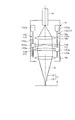
- FIG. 6 is a schematic configuration diagram schematically showing an irradiation head of the laser processing apparatus according to the present embodiment.
- FIG. 7 shows the laser irradiated to the workpiece from the irradiation head shown in FIG. It is the enlarged plan view seen in (direction along the extension direction of an optical axis).
- the irradiation head 16 includes a parallel optical system 16 b that converts the laser beam incident from the guide optical system 14 into parallel light inside the casing 16 a supported by the moving mechanism 18 described above, and a parallel optical system.
- a condensing optical system 16c that condenses the laser beam collimated by 16b on the optical axis S is provided.
- the parallel optical system 16b and the condensing optical system 16c shown in FIG. 6 are schematic, and the lens configuration is not limited.
- the focused laser L is irradiated to the workpiece 8.
- the laser output device 12 oscillates a laser having a plurality of (two in FIG. 6) wavelength bands. This laser is converted into parallel light by the parallel optical system 16b and condensed by the condensing optical system 16c in the irradiation head 16, but the focal lengths of the lasers L1 and L2 of each wavelength band are shifted on the same optical axis S. Condensed and irradiated.
- the focal position of the laser L2 having a short wavelength is matched with the processing position of the workpiece 8 (the surface of the workpiece 8).
- a laser L1 having a long wavelength in the focal point is condensed. That is, the focus of the laser L2 with the short wavelength is adjusted to the processing position of the workpiece 8, and the laser L1 having a long wavelength is collected so as to surround the laser L2 around the focus of the laser L2 with the short wavelength. Is done.
- the short wavelength laser L ⁇ b> 2 whose focal point is adjusted to the processing position of the workpiece 8 is used for processing the workpiece 8.
- the long-wavelength laser L1 focused around the short-wavelength laser L2 increases the viscosity of the metal melted by radiation from plasma generated by melting the workpiece 8 by the short-wavelength laser L2. Lowering improves processing quality.
- the semiconductor laser of this embodiment has wavelength bands of 808 nm and 10.6 ⁇ m.
- the workpiece 8 is iron or mild steel, the effect of the laser absorption rate as in the first embodiment is small. Therefore, the short wavelength laser L2 is set to the wavelength band of 808 nm, the long wavelength laser L1 is set to the wavelength band of 10.6 ⁇ m, the long wavelength side is condensed on the outer periphery, and the workpiece 8 is focused on the focal point on the short wavelength side. Match the machining position.
- the temperature of the metal melted by the radiation from the plasma generated by melting the workpiece 8 is raised by the long-wavelength laser L1 to lower the viscosity. This improves the processing quality.
- the laser processing apparatus 10 of the present embodiment condenses the laser output apparatus 12 that oscillates a laser having a plurality of wavelength bands and the lasers of each wavelength band on the same optical axis S while shifting the focal length.
- this laser processing apparatus 10 by including the laser output device 12 that oscillates a laser having a plurality of wavelength bands, it is possible to oscillate a laser having a plurality of wavelength bands without increasing the size of the apparatus.
- the irradiation head 16 that condenses and irradiates lasers in the respective wavelength bands on the same optical axis S while shifting the focal length, the wavelength band for processing and the wavelength band for assisting the processing are the same light. Irradiation on the axis S allows machining and machining assistance to be performed simultaneously in a series of machining operations. As a result, the configuration can be simplified even when lasers having different wavelength bands are used.
- the irradiation head 16 matches the focal position of the laser L2 having a short wavelength with the position to be processed, and the laser L1 having a long wavelength with the short wavelength laser L2 in focus. It is preferable to collect light.
- the focus of the short wavelength laser L2 is arranged in the condensing of the long wavelength laser L1 having a relatively high power density, so that the workpiece 8 is moved by the short wavelength laser L2. Since the temperature of the metal melted by the radiation from the plasma generated by melting the workpiece 8 is raised by the long-wave laser L1 and the viscosity is lowered while being melted and processed, the processing quality can be improved.
- the laser processing apparatus 10 of the present embodiment moves the irradiation head 16 by the moving mechanism 18 while detecting the position of the irradiation head 16 in the XYZ directions by the position detector 34.
- the focal position of the long wavelength laser L1 and the focal length of the short wavelength laser L2 are determined by the parallel optical system 16b and the condensing optical system 16c. Is stored in advance.
- the control device 22 moves the moving mechanism 18 so that the focus of the laser L (short-wavelength laser L2 in this embodiment) is adjusted to the processing position of the processing member 8. The focus can be easily aligned with the processing position.
- the irradiation head 16 has the focal distance adjustment apparatus 17 (refer FIG. 5).
- the focal length adjusting device 17 includes, for example, a concave glass 17A and a convex glass 17B, and includes a glass moving mechanism 17C that enables the concave glass 17A and the convex glass 17B to move in the optical axis direction.
- the glass moving mechanism 17C is, for example, a support member 17Ca that supports the concave glass 17A and the convex glass 17B, and a guide that extends in the optical axis direction and moves each support member 17Ca in the optical axis direction.
- Guide rails 17Cb screw rods 17Cc that extend in the direction of the optical axis and are threadedly inserted into the support members 17Ca, and drive motors 17Cd that rotationally drive the screw rods 17Cc. That is, the glass moving mechanism 17C drives each drive motor 17Cd to rotate each screw rod 17Cc, so that each support member 17Ca is accompanied by the concave glass 17A and the convex glass 17B in the optical axis direction along the guide rail 17Cb. Moving. Thereby, the concave glass 17A and the convex glass 17B move in the optical axis direction, and the focal lengths of the lasers L1 and L2 having different wavelength bands are changed.
- the focal length adjusting device 17 is controlled by the control device 22.
- the moving distance between the concave glass 17A and the convex glass 17B, that is, the focal length is controlled in accordance with the rotational speed of the screw rod 17Cc by the drive motor 17Cd.
- the laser processing apparatus 10 changes the focal length of the lasers L1 and L2 having different wavelength bands by the focal length adjusting device 17, thereby the laser L (the laser L2 having a short wavelength in the present embodiment). ) May be adjusted to the processing position of the workpiece 8, and the focus can be easily aligned with the processing position of the processing member 8.
Abstract
波長帯の異なるレーザを用いても構成を簡素化するため、複数の波長帯を有するレーザ(L1,L2)を発振するレーザ出力装置と、各波長帯のレーザ(L1,L2)を同一光軸S上で焦点距離をずらして集光し照射する照射ヘッド(16)と、を備える。
Description
本発明は、加工対象の部材にレーザを照射して加工を行うレーザ加工装置に関するものである。
加工対象の部材の穴開け、切断、溶接、をレーザの照射により加工する場合、加工性能および加工品質を確保するため、レーザをより小さなスポットに集光させてパワー密度を上げることが好ましい。また、加工対象の部材として金属への吸収を高めて反射を低減することが好ましい。
従来、小さなスポットに高密度に集光が可能な長波長のレーザと、金属への吸収性の高い短波長のレーザとを用いて加工を行うことが、例えば、特許文献1~特許文献3に示されている。
上述した特許文献1~特許文献3に記載のレーザ加工装置は、波長帯の異なるレーザをそれぞれ異なる発振源により発生させている。このため、装置の大型化が懸念される。特に、特許文献1では、波長帯の異なるレーザを別々に加工対象の部材に照射させているため、別々の光学系や加工ヘッドや移動機構などが必要となり、部品点数が嵩んで装置構成が複雑化し、装置が大型化することになる。また、特許文献2および特許文献3では、波長帯の異なるレーザを重畳して同じ光軸上に集光させているため、重畳するための光学系が複雑化することになる。
本発明は上述した課題を解決するものであり、波長帯の異なるレーザを用いても構成を簡素化することのできるレーザ加工装置を提供することを目的とする。
上述の目的を達成するために、本発明のレーザ加工装置は、複数の波長帯を有するレーザを発振するレーザ出力装置と、各波長帯のレーザを同一光軸上で焦点距離をずらして集光し照射する照射ヘッドと、を備えることを特徴とする。
このレーザ加工装置によれば、複数の波長帯を有するレーザを発振するレーザ出力装置を備えることで、装置の大型化を招くことなく複数の波長帯のレーザを発振することができる。しかも、各波長帯のレーザを同一光軸上で焦点距離をずらして集光し照射する照射ヘッドを備えることで、加工を行う波長帯と、当該加工を助勢する波長帯とを同一光軸上で照射し、加工および加工助勢を一連の加工動作において同時に行うことができる。この結果、波長帯の異なるレーザを用いても構成を簡素化することができる。
また、本発明のレーザ加工装置では、前記照射ヘッドは、長波長となるレーザの焦点位置を被加工位置に合わせ、前記長波長のレーザの焦点を中において短波長となるレーザを集光させることを特徴とする。
このレーザ加工装置によれば、高密度に集光が可能である長波長のレーザの焦点を加工位置に合わせ、吸収率が高い短波長のレーザを長波長のレーザの焦点を中において集光させることで、外周の短波長のレーザで被加工部材を予熱し、予熱された被加工部材を長波長のレーザで加工する。この結果、加工に伴い予熱を行うことで、加工速度および加工品質を向上することができる。
また、本発明のレーザ加工装置では、前記照射ヘッドは、短波長となるレーザの焦点位置を被加工位置に合わせ、前記短波長のレーザの焦点を中において長波長となるレーザを集光させることを特徴とする。
このレーザ加工装置によれば、パワー密度の比較的高い長波長のレーザの集光の中に短波長のレーザの焦点を配置することで、短波長のレーザにより被加工部材を溶かして加工しつつ、被加工部材を溶かして生じるプラズマからの輻射によって溶かした金属の温度を長波長のレーザにより上げて粘性を下げるため、加工品質を向上することができる。
また、本発明のレーザ加工装置では、光軸方向にそれぞれ移動可能な、凹ガラスと凸ガラスを備える焦点距離調整装置を有することを特徴とする。
このレーザ加工装置によれば、焦点距離調整装置により波長帯の異なる各レーザの焦点距離を変更することで、被加工位置への焦点の位置合わせを容易に行うことができる。
また、本発明のレーザ加工装置では、被加工部材を支持する支持台と前記照射ヘッドとを相対移動させる移動機構と、前記移動機構による前記支持台と前記照射ヘッドとの相対移動およびレーザ出力装置から出力するレーザの各種条件を調整する制御装置と、を備えることを特徴とする。
このレーザ加工装置によれば、移動機構による支持台と照射ヘッドとの相対移動およびレーザ出力装置から出力するレーザの各種条件を調整することで、波長帯の異なるレーザを用いても構成を簡素化しつつ、レーザによる被加工部材の加工を行うことができる。
本発明によれば、波長帯の異なるレーザを用いても構成を簡素化することができる。
以下に、本発明に係るレーザ加工装置の一実施形態を図面に基づいて詳細に説明する。なお、この実施形態によりこの発明が限定されるものではない。例えば、本実施形態では、板状の被加工部材を加工する場合として説明するが、被加工部材の形状は特に限定されない。被加工部材の形状は、種々の形状とすることができる。また、本実施形態では、被加工部材に穴を形成する場合、被加工部材を直線上に切断する場合、または被加工部材を溶接する場合として説明するが、被加工部材上における加工位置、つまりレーザの照射位置を調整することで、穴や直線以外の形状、例えば、屈曲点を有する形状、湾曲した形状とすることもできる。また、本実施形態では、被加工部材を移動させることで、レーザと被加工部材とを相対的に移動させたが、レーザを移動させるようにしてもよく、レーザと被加工部材の両方を移動させてもよい。
図1は、本実施形態に係るレーザ加工装置を模式的に表した概略構成図である。レーザ加工装置10は、図1に示すように、レーザ出力装置12と、案内光学系14と、照射ヘッド16と、移動機構18と、支持台20と、制御装置22と、を有する。レーザ加工装置10は、支持台20に設置された被加工部材8にレーザLを照射することで、被加工部材8を加工する。ここで、本実施形態において、レーザ加工装置10は、被加工部材8の表面をXY平面とし、被加工部材8の表面に直交する方向をZ方向とする。
ここで、本実施形態の被加工部材8は、板状の部材である。被加工部材8としては、種々の材料、例えば、インコネル、ハステロイ、ステンレス、セラミック、鋼、炭素鋼、セラミックス、シリコン、チタン、タングステン、樹脂、プラスチックス、ガラスなどで作成された部材を用いることができる。また、被加工部材8には、CFRP(炭素繊維強化プラスチック、Carbon Fiber Reinforced Plastics)、GFRP(ガラス繊維強化プラスチック)、GMT(ガラス長繊維強化プラスチック)などの繊維強化プラスチック、鋼板以外の鉄合金、アルミニウム合金などの各種金属、その他複合材料などで作成された部材も用いることができる。また、溶接する際には、溶加材や粉末などを供給する機構を有してもよい。
レーザ出力装置12は、レーザを出力する装置である。レーザ出力装置12は、複数の波長帯を有するレーザを発振する。このレーザ出力装置12は、例えば、半導体レーザ発振器がある。
案内光学系14は、レーザ出力装置12から出力されたレーザを照射ヘッド16に案内する光学系である。本実施形態の案内光学系14は、光ファイバである。案内光学系14は、一方の端部がレーザ出力装置12のレーザの出射口と接続され、他方の端部が照射ヘッド16に接続されている。案内光学系14は、レーザ出力装置12から出力されたレーザを照射ヘッド16の入射端に向かって出力する。なお、案内光学系14の構成はこれに限定されない。レーザ加工装置10は、案内光学系14としてミラーやレンズの組み合わせを用い、レーザを反射、集光などすることで、照射ヘッド16に案内してもよい。または、レーザ出力装置12から照射ヘッド16に直接案内してもよい。
照射ヘッド16は、案内光学系14から出力されるレーザLを被加工部材8に照射する。照射ヘッド16の詳細は後述する。
移動機構18は、アーム30と、アーム30を移動させる駆動源32と、を有する。アーム30は、先端で照射ヘッド16を支持している。駆動源32は、アーム30をXYZの3軸方向に移動させることができる。移動機構18は、駆動源32でアーム30をXYZ方向に移動させることで、被加工部材8の種々の位置に照射ヘッド16からのレーザLを照射することができる。また、移動機構18は、照射ヘッド16のXYZ方向の位置を検出する位置検出器34を有している。なお、本実施形態は、移動機構18として、アーム30と駆動源32で照射ヘッド16を移動させる機構としたが、XYステージ、XYZステージなどで照射ヘッド16を移動する機構も用いることができる。
支持台20は、被加工部材8を所定位置に支持する。なお、レーザ加工装置10は、支持台20が、被加工部材8をXY方向に移動させるXYステージとして構成されていてもよい。
制御装置22は、各部の動作を制御する。制御装置22は、レーザ出力装置12から出力するレーザの各種条件を調整したり、移動機構18で照射ヘッド16を移動させ被加工部材8に対する照射ヘッド16の位置を調整したりする。
このレーザ加工装置10は、レーザ出力装置12からレーザを出力させる。レーザ加工装置10は、出力されたレーザLを案内光学系14で照射ヘッド16に案内する。レーザ加工装置10は、位置検出器34で照射ヘッド16のXYZ方向の位置を検出しつつ移動機構18により照射ヘッド16を移動させる。これにより、レーザ加工装置10は、被加工部材8を加工することができる。
[実施形態1]
図2は、本実施形態に係るレーザ加工装置の照射ヘッドを模式的に表した概略構成図であり、図3は、図2に示す照射ヘッドから被加工部材に照射されるレーザを光軸方向(光軸の延在方向に沿う方向)で視た拡大平面図であり、図4は、レーザの波長と被加工部材の吸収率との関係を示す図である。
図2は、本実施形態に係るレーザ加工装置の照射ヘッドを模式的に表した概略構成図であり、図3は、図2に示す照射ヘッドから被加工部材に照射されるレーザを光軸方向(光軸の延在方向に沿う方向)で視た拡大平面図であり、図4は、レーザの波長と被加工部材の吸収率との関係を示す図である。
図2に示すように、照射ヘッド16は、上述した移動機構18により支持されるケーシング16aの内部に、案内光学系14から入射されたレーザを平行光とする平行光学系16bと、平行光学系16bにより平行光とされたレーザを光軸S上に集光する集光光学系16cとが設けられている。なお、図2に示す平行光学系16bおよび集光光学系16cは、模式化したものであり、レンズ構成について限定されるものではない。
この照射ヘッド16では、集光されたレーザLは、被加工部材8に照射される。本実施形態において、レーザ出力装置12が複数(図2では2つ)の波長帯を有するレーザを発振している。このレーザは、照射ヘッド16において、平行光学系16bで平行光とされ、集光光学系16cで集光されるが、各波長帯のレーザL1,L2を同一光軸S上で焦点距離をずらして集光し照射する。本実施形態では、図2および図3に示すように、長波長となるレーザL1の焦点位置を被加工部材8の被加工位置(被加工部材8の表面)に合わせ、長波長のレーザL1の焦点を中において短波長となるレーザL2を集光させる。すなわち、長波長のレーザL1の焦点が被加工部材8の被加工位置に合わされ、この長波長のレーザL1の焦点を中心として当該レーザL1の周りを囲むように短波長となるレーザL2が集光される。
長波長のレーザL1は、小さなスポットに高密度に集光が可能であり、短波長のレーザL2は、被加工部材8への吸収性が高い。このため、外周の短波長のレーザL2により被加工部材8が予熱され、予熱された被加工部材8が内側の長波長のレーザL1により加工される。従って、加工に伴い予熱を行うことで、加工速度および加工品質を向上することができる。
例えば、本実施形態の半導体レーザとして、808nmと940nmとの波長帯を有するとする。また、被加工部材8がアルミニウム合金である場合、このアルミニウム合金のレーザ波長に対する吸収率は、図4に示すように、900nm近辺にある。そして、本実施形態では、吸収率が高い808nmの波長帯を短波長のレーザL2とし、940nmの波長帯を長波長のレーザL1としている。このように、被加工部材8の吸収波長に近似する複数の波長帯を用い、かつ吸収率が高い方を短波長側として外周に集光し、高密度に集光が可能である長波長側の焦点を中心として被加工部材8の加工位置に合わせる。これにより、予熱および加工を行い、アルミニウム合金に対する加工速度および加工品質を向上することができる。なお、一般にレーザ加工に用いられているCO2レーザは、波長が106μmであり、Nd:YAGレーザ(ネオジムヤグレーザ)は、波長が10.6μmであって、半導体レーザと比較するとアルミニウム合金の吸収波長900nmから離れている。このため、CO2レーザとNd:YAGレーザとで異なる波長帯としたとしても、半導体レーザによるアルミニウム合金の加工速度および加工品質を再現することは難しい。
このように、本実施形態のレーザ加工装置10は、複数の波長帯を有するレーザを発振するレーザ出力装置12と、各波長帯のレーザを同一光軸上で焦点距離をずらして集光し照射する照射ヘッド16と、を備える。
このレーザ加工装置10によれば、複数の波長帯を有するレーザを発振するレーザ出力装置12を備えることで、装置の大型化を招くことなく複数の波長帯のレーザを発振することができる。しかも、各波長帯のレーザを同一光軸S上で焦点距離をずらして集光し照射する照射ヘッド16を備えることで、加工を行う波長帯と、当該加工を助勢する波長帯とを同一光軸S上で照射し、加工および加工助勢を一連の加工動作において同時に行うことができる。この結果、波長帯の異なるレーザを用いても構成を簡素化することができる。
また、本実施形態のレーザ加工装置10では、照射ヘッド16は、長波長となるレーザL1の焦点位置を被加工位置に合わせ、長波長のレーザL1の焦点を中において短波長となるレーザL2を集光させることが好ましい。
このレーザ加工装置10によれば、高密度に集光が可能である長波長のレーザL1の焦点を被加工部材8の加工位置に合わせ、吸収率が高い短波長のレーザL2を長波長のレーザL1の焦点を中において集光させることで、外周の短波長のレーザL2で被加工部材8を予熱し、予熱された被加工部材8を長波長のレーザL1で加工する。この結果、加工に伴い予熱を行うことで、加工速度および加工品質を向上することができる。
なお、本実施形態のレーザ加工装置10は、位置検出器34で照射ヘッド16のXYZ方向の位置を検出しつつ移動機構18により照射ヘッド16を移動させる。また、照射ヘッド16では、平行光学系16bおよび集光光学系16cにより長波長のレーザL1の焦点位置および短波長のレーザL2の焦点距離が決められており、この焦点距離の情報が制御装置22に予め記憶されている。このため、制御装置22により、移動機構18を移動させてレーザL(本実施形態では長波長のレーザL1)の焦点を被加工部材8の被加工位置に合わせることで、被加工部材8の被加工位置への焦点の位置合わせを容易に行うことができる。
なお、図5は、本実施形態に係るレーザ加工装置の他の照射ヘッドを模式的に表した概略構成図である。図5に示す照射ヘッド16は、焦点距離調整装置17を有している。焦点距離調整装置17は、例えば、凹ガラス17Aと凸ガラス17Bとを有し、これら凹ガラス17Aと凸ガラス17Bとを光軸方向にそれぞれ移動可能にするガラス移動機構17Cを有している。ガラス移動機構17Cは、例えば、凹ガラス17Aと凸ガラス17Bとをそれぞれ支持する支持部材17Caと、光軸方向に延在して設けられて各支持部材17Caを光軸方向に移動するように案内する案内レール17Cbと、光軸方向に延在して設けられて各支持部材17Caに螺合して挿通されるネジ棒17Ccと、各ネジ棒17Ccを回転駆動する駆動モータ17Cdとを備える。すなわち、ガラス移動機構17Cは、各駆動モータ17Cdを駆動して各ネジ棒17Ccを回転させることで、各支持部材17Caが凹ガラス17Aや凸ガラス17Bを伴い案内レール17Cbに沿って光軸方向に移動する。これにより、凹ガラス17Aと凸ガラス17Bとが光軸方向にそれぞれ移動し、波長帯の異なる各レーザL1,L2の焦点距離が変更される。この焦点距離調整装置17は、制御装置22により制御される。制御装置22では、駆動モータ17Cdによるネジ棒17Ccの回転数に応じて凹ガラス17Aと凸ガラス17Bとの移動距離、すなわち焦点距離を制御する。このように、本実施形態のレーザ加工装置10は、焦点距離調整装置17により波長帯の異なる各レーザL1,L2の焦点距離を変更することで、レーザL(本実施形態では長波長のレーザL1)の焦点を被加工部材8の被加工位置に合わせてもよく、被加工部材8の被加工位置への焦点の位置合わせを容易に行うことができる。
[実施形態2]
図6は、本実施形態に係るレーザ加工装置の照射ヘッドを模式的に表した概略構成図であり、図7は、図6に示す照射ヘッドから被加工部材に照射されるレーザを光軸方向(光軸の延在方向に沿う方向)で視た拡大平面図である。
図6は、本実施形態に係るレーザ加工装置の照射ヘッドを模式的に表した概略構成図であり、図7は、図6に示す照射ヘッドから被加工部材に照射されるレーザを光軸方向(光軸の延在方向に沿う方向)で視た拡大平面図である。
図6に示すように、照射ヘッド16は、上述した移動機構18により支持されるケーシング16aの内部に、案内光学系14から入射されたレーザを平行光とする平行光学系16bと、平行光学系16bにより平行光とされたレーザを光軸S上に集光する集光光学系16cとが設けられている。なお、図6に示す平行光学系16bおよび集光光学系16cは、模式化したものであり、レンズ構成について限定されるものではない。
この照射ヘッド16では、集光されたレーザLは、被加工部材8に照射される。本実施形態において、レーザ出力装置12が複数(図6では2つ)の波長帯を有するレーザを発振している。このレーザは、照射ヘッド16において、平行光学系16bで平行光とされ、集光光学系16cで集光されるが、各波長帯のレーザL1,L2を同一光軸S上で焦点距離をずらして集光し照射する。本実施形態では、図6および図7に示すように、短波長となるレーザL2の焦点位置を被加工部材8の被加工位置(被加工部材8の表面)に合わせ、短波長のレーザL2の焦点を中において長波長となるレーザL1を集光させる。すなわち、短波長のレーザL2の焦点が被加工部材8の被加工位置に合わされ、この短波長のレーザL2の焦点を中心として当該レーザL2の周りを囲むように長波長となるレーザL1が集光される。
焦点が被加工部材8の被加工位置に合わされた短波長のレーザL2は、被加工部材8の加工に用いられる。また、短波長のレーザL2の周りに集光された長波長のレーザL1は、短波長のレーザL2により被加工部材8を溶かして生じるプラズマからの輻射によって溶かした金属の温度を上げて粘性を下げることで加工品質を向上する。
例えば、本実施形態の半導体レーザとして、808nmと10.6μmとの波長帯を有するとする。また、被加工部材8が鉄や軟鋼である場合、上述した実施形態1のようなレーザの吸収率による効果が小さい。そこで、808nmの波長帯を短波長のレーザL2とし、10.6μmの波長帯を長波長のレーザL1として、長波長側を外周に集光し、短波長側の焦点を中心として被加工部材8の加工位置に合わせる。これにより、短波長のレーザL2により被加工部材8を溶かして加工しつつ、被加工部材8を溶かして生じるプラズマからの輻射によって溶かした金属の温度を長波長のレーザL1により上げて粘性を下げることで加工品質を向上する。
このように、本実施形態のレーザ加工装置10は、複数の波長帯を有するレーザを発振するレーザ出力装置12と、各波長帯のレーザを同一光軸S上で焦点距離をずらして集光し照射する照射ヘッド16と、を備える。
このレーザ加工装置10によれば、複数の波長帯を有するレーザを発振するレーザ出力装置12を備えることで、装置の大型化を招くことなく複数の波長帯のレーザを発振することができる。しかも、各波長帯のレーザを同一光軸S上で焦点距離をずらして集光し照射する照射ヘッド16を備えることで、加工を行う波長帯と、当該加工を助勢する波長帯とを同一光軸S上で照射し、加工および加工助勢を一連の加工動作において同時に行うことができる。この結果、波長帯の異なるレーザを用いても構成を簡素化することができる。
また、本実施形態のレーザ加工装置10では、照射ヘッド16は、短波長となるレーザL2の焦点位置を被加工位置に合わせ、短波長のレーザL2の焦点を中において長波長となるレーザL1を集光させることが好ましい。
このレーザ加工装置10によれば、パワー密度の比較的高い長波長のレーザL1の集光の中に短波長のレーザL2の焦点を配置することで、短波長のレーザL2により被加工部材8を溶かして加工しつつ、被加工部材8を溶かして生じるプラズマからの輻射によって溶かした金属の温度を長波長のレーザL1により上げて粘性を下げるため、加工品質を向上することができる。
なお、本実施形態のレーザ加工装置10は、位置検出器34で照射ヘッド16のXYZ方向の位置を検出しつつ移動機構18により照射ヘッド16を移動させる。また、照射ヘッド16では、平行光学系16bおよび集光光学系16cにより長波長のレーザL1の焦点位置および短波長のレーザL2の焦点距離が決められており、この焦点距離の情報が制御装置22に予め記憶されている。このため、制御装置22により、移動機構18を移動させてレーザL(本実施形態では短波長のレーザL2)の焦点を被加工部材8の被加工位置に合わせることで、被加工部材8の被加工位置への焦点の位置合わせを容易に行うことができる。
なお、本実施形態のレーザ加工装置10では、照射ヘッド16は、焦点距離調整装置17を有している(図5参照)。焦点距離調整装置17は、例えば、凹ガラス17Aと凸ガラス17Bとを有し、これら凹ガラス17Aと凸ガラス17Bとを光軸方向にそれぞれ移動可能にするガラス移動機構17Cを有している。ガラス移動機構17Cは、例えば、凹ガラス17Aと凸ガラス17Bとをそれぞれ支持する支持部材17Caと、光軸方向に延在して設けられて各支持部材17Caを光軸方向に移動するように案内する案内レール17Cbと、光軸方向に延在して設けられて各支持部材17Caに螺合して挿通されるネジ棒17Ccと、各ネジ棒17Ccを回転駆動する駆動モータ17Cdとを備える。すなわち、ガラス移動機構17Cは、各駆動モータ17Cdを駆動して各ネジ棒17Ccを回転させることで、各支持部材17Caが凹ガラス17Aや凸ガラス17Bを伴い案内レール17Cbに沿って光軸方向に移動する。これにより、凹ガラス17Aと凸ガラス17Bとが光軸方向にそれぞれ移動し、波長帯の異なる各レーザL1,L2の焦点距離が変更される。この焦点距離調整装置17は、制御装置22により制御される。制御装置22では、駆動モータ17Cdによるネジ棒17Ccの回転数に応じて凹ガラス17Aと凸ガラス17Bとの移動距離、すなわち焦点距離を制御する。このように、本実施形態のレーザ加工装置10は、焦点距離調整装置17により波長帯の異なる各レーザL1,L2の焦点距離を変更することで、レーザL(本実施形態では短波長のレーザL2)の焦点を被加工部材8の被加工位置に合わせてもよく、被加工部材8の被加工位置への焦点の位置合わせを容易に行うことができる。
8 被加工部材
10 レーザ加工装置
12 レーザ出力装置
16 照射ヘッド
S 光軸
10 レーザ加工装置
12 レーザ出力装置
16 照射ヘッド
S 光軸
Claims (5)
- 複数の波長帯を有するレーザを発振するレーザ出力装置と、
各波長帯のレーザを同一光軸上で焦点距離をずらして集光し照射する照射ヘッドと、
を備えることを特徴とするレーザ加工装置。 - 前記照射ヘッドは、長波長となるレーザの焦点位置を被加工位置に合わせ、前記長波長のレーザの焦点を中において短波長となるレーザを集光させることを特徴とする請求項1に記載のレーザ加工装置。
- 前記照射ヘッドは、短波長となるレーザの焦点位置を被加工位置に合わせ、前記短波長のレーザの焦点を中において長波長となるレーザを集光させることを特徴とする請求項1に記載のレーザ加工装置。
- 光軸方向にそれぞれ移動可能な、凹ガラスと凸ガラスを備える焦点距離調整装置を有することを特徴とする請求項1~3のいずれか一つに記載のレーザ加工装置。
- 被加工部材を支持する支持台と前記照射ヘッドとを相対移動させる移動機構と、
前記移動機構による前記支持台と前記照射ヘッドとの相対移動およびレーザ出力装置から出力するレーザの各種条件を調整する制御装置と、
を備えることを特徴とする請求項1~4のいずれか一つに記載のレーザ加工装置。
Priority Applications (2)
| Application Number | Priority Date | Filing Date | Title |
|---|---|---|---|
| US14/914,211 US20160207144A1 (en) | 2013-08-28 | 2014-02-26 | Laser processing apparatus |
| EP14839926.4A EP3025819A4 (en) | 2013-08-28 | 2014-02-26 | LASER PROCESSING DEVICE |
Applications Claiming Priority (2)
| Application Number | Priority Date | Filing Date | Title |
|---|---|---|---|
| JP2013177395 | 2013-08-28 | ||
| JP2013-177395 | 2013-08-28 |
Publications (1)
| Publication Number | Publication Date |
|---|---|
| WO2015029466A1 true WO2015029466A1 (ja) | 2015-03-05 |
Family
ID=52586051
Family Applications (1)
| Application Number | Title | Priority Date | Filing Date |
|---|---|---|---|
| PCT/JP2014/054735 WO2015029466A1 (ja) | 2013-08-28 | 2014-02-26 | レーザ加工装置 |
Country Status (3)
| Country | Link |
|---|---|
| US (1) | US20160207144A1 (ja) |
| EP (1) | EP3025819A4 (ja) |
| WO (1) | WO2015029466A1 (ja) |
Cited By (3)
| Publication number | Priority date | Publication date | Assignee | Title |
|---|---|---|---|---|
| CN110121397A (zh) * | 2017-09-26 | 2019-08-13 | 三菱电机株式会社 | 激光加工方法以及激光加工装置 |
| WO2021107042A1 (ja) * | 2019-11-27 | 2021-06-03 | パナソニックIpマネジメント株式会社 | レーザ発振器 |
| JP2022543152A (ja) * | 2019-08-06 | 2022-10-07 | パナソニックIpマネジメント株式会社 | デュアル波長レーザシステム及びそのシステムを用いた材料加工 |
Families Citing this family (3)
| Publication number | Priority date | Publication date | Assignee | Title |
|---|---|---|---|---|
| JP6254036B2 (ja) * | 2014-03-31 | 2017-12-27 | 三菱重工業株式会社 | 三次元積層装置及び三次元積層方法 |
| KR20170087610A (ko) * | 2016-01-21 | 2017-07-31 | 삼성전자주식회사 | 웨이퍼 절단 장치 |
| JP6577110B2 (ja) * | 2017-10-06 | 2019-09-18 | 株式会社アマダホールディングス | レーザ加工方法及びレーザ加工装置 |
Citations (9)
| Publication number | Priority date | Publication date | Assignee | Title |
|---|---|---|---|---|
| JPS63295093A (ja) | 1987-01-30 | 1988-12-01 | ウアルター・ダブリユ・ダーレイ | 金属のレーザー加工効率を向上させる手段 |
| JPH0180285U (ja) * | 1987-11-18 | 1989-05-30 | ||
| JPH03124389A (ja) * | 1989-10-05 | 1991-05-27 | Toshiba Corp | レーザ加工装置 |
| JPH03146286A (ja) * | 1989-11-01 | 1991-06-21 | Toshiba Corp | 水中レーザー溶接装置 |
| JP2001196665A (ja) | 2000-01-13 | 2001-07-19 | Hamamatsu Kagaku Gijutsu Kenkyu Shinkokai | 二波長レーザ加工光学装置およびレーザ加工方法 |
| JP2001321978A (ja) * | 2000-03-07 | 2001-11-20 | Amada Eng Center Co Ltd | レーザ加工方法およびその装置 |
| JP2006263771A (ja) | 2005-03-24 | 2006-10-05 | Mitsubishi Heavy Ind Ltd | レーザ加工装置及びレーザ加工方法 |
| JP2010158686A (ja) * | 2009-01-06 | 2010-07-22 | Disco Abrasive Syst Ltd | レーザ加工用光学装置、レーザ加工装置およびレーザ加工方法 |
| WO2011001765A1 (ja) * | 2009-06-29 | 2011-01-06 | 西進商事株式会社 | レーザー照射装置及びレーザー加工方法 |
Family Cites Families (7)
| Publication number | Priority date | Publication date | Assignee | Title |
|---|---|---|---|---|
| JP4167370B2 (ja) * | 1999-12-22 | 2008-10-15 | パイオニア株式会社 | 光ピックアップ装置 |
| WO2001064591A1 (en) * | 2000-03-01 | 2001-09-07 | Heraeus Amersil, Inc. | Method, apparatus, and article of manufacture for determining an amount of energy needed to bring a quartz workpiece to a fusion weldable condition |
| JP2004358521A (ja) * | 2003-06-05 | 2004-12-24 | Mitsubishi Heavy Ind Ltd | レーザ熱加工装置、レーザ熱加工方法 |
| JP5133568B2 (ja) * | 2007-01-11 | 2013-01-30 | 株式会社ディスコ | レーザー加工装置 |
| JP5241525B2 (ja) * | 2009-01-09 | 2013-07-17 | 浜松ホトニクス株式会社 | レーザ加工装置 |
| JP2012045570A (ja) * | 2010-08-26 | 2012-03-08 | Kobe Steel Ltd | アルミニウム接合体の製造方法 |
| JP5642493B2 (ja) * | 2010-10-15 | 2014-12-17 | 三菱重工業株式会社 | レーザ切断装置及びレーザ切断方法 |
-
2014
- 2014-02-26 WO PCT/JP2014/054735 patent/WO2015029466A1/ja active Application Filing
- 2014-02-26 EP EP14839926.4A patent/EP3025819A4/en not_active Withdrawn
- 2014-02-26 US US14/914,211 patent/US20160207144A1/en not_active Abandoned
Patent Citations (9)
| Publication number | Priority date | Publication date | Assignee | Title |
|---|---|---|---|---|
| JPS63295093A (ja) | 1987-01-30 | 1988-12-01 | ウアルター・ダブリユ・ダーレイ | 金属のレーザー加工効率を向上させる手段 |
| JPH0180285U (ja) * | 1987-11-18 | 1989-05-30 | ||
| JPH03124389A (ja) * | 1989-10-05 | 1991-05-27 | Toshiba Corp | レーザ加工装置 |
| JPH03146286A (ja) * | 1989-11-01 | 1991-06-21 | Toshiba Corp | 水中レーザー溶接装置 |
| JP2001196665A (ja) | 2000-01-13 | 2001-07-19 | Hamamatsu Kagaku Gijutsu Kenkyu Shinkokai | 二波長レーザ加工光学装置およびレーザ加工方法 |
| JP2001321978A (ja) * | 2000-03-07 | 2001-11-20 | Amada Eng Center Co Ltd | レーザ加工方法およびその装置 |
| JP2006263771A (ja) | 2005-03-24 | 2006-10-05 | Mitsubishi Heavy Ind Ltd | レーザ加工装置及びレーザ加工方法 |
| JP2010158686A (ja) * | 2009-01-06 | 2010-07-22 | Disco Abrasive Syst Ltd | レーザ加工用光学装置、レーザ加工装置およびレーザ加工方法 |
| WO2011001765A1 (ja) * | 2009-06-29 | 2011-01-06 | 西進商事株式会社 | レーザー照射装置及びレーザー加工方法 |
Non-Patent Citations (1)
| Title |
|---|
| See also references of EP3025819A4 |
Cited By (4)
| Publication number | Priority date | Publication date | Assignee | Title |
|---|---|---|---|---|
| CN110121397A (zh) * | 2017-09-26 | 2019-08-13 | 三菱电机株式会社 | 激光加工方法以及激光加工装置 |
| JP2022543152A (ja) * | 2019-08-06 | 2022-10-07 | パナソニックIpマネジメント株式会社 | デュアル波長レーザシステム及びそのシステムを用いた材料加工 |
| JP7445879B2 (ja) | 2019-08-06 | 2024-03-08 | パナソニックIpマネジメント株式会社 | デュアル波長レーザシステム及びそのシステムを用いた材料加工 |
| WO2021107042A1 (ja) * | 2019-11-27 | 2021-06-03 | パナソニックIpマネジメント株式会社 | レーザ発振器 |
Also Published As
| Publication number | Publication date |
|---|---|
| EP3025819A4 (en) | 2016-09-28 |
| EP3025819A1 (en) | 2016-06-01 |
| US20160207144A1 (en) | 2016-07-21 |
Similar Documents
| Publication | Publication Date | Title |
|---|---|---|
| JP6025798B2 (ja) | レーザ加工装置 | |
| WO2015029466A1 (ja) | レーザ加工装置 | |
| CN107584205B (zh) | 金属材料的激光加工方法以及相关的机器和计算机程序 | |
| KR101718265B1 (ko) | 가공장치 및 가공방법 | |
| US10792759B2 (en) | Laser processing method and laser processing apparatus | |
| JP6071641B2 (ja) | 加工装置、加工方法 | |
| JP2007181840A (ja) | レーザ照射アーク溶接ヘッド | |
| JP6071640B2 (ja) | 加工装置、加工方法 | |
| JP5642493B2 (ja) | レーザ切断装置及びレーザ切断方法 | |
| JP2009178720A (ja) | レーザ加工装置 | |
| JP2010201479A (ja) | レーザ光加工装置及びレーザ光加工方法 | |
| JP5595568B1 (ja) | レーザ加工装置 | |
| JP5595573B1 (ja) | レーザ加工装置及びレーザ加工方法 | |
| WO2016059937A1 (ja) | ダイレクトダイオードレーザ光による板金の加工方法及びこれを実行するダイレクトダイオードレーザ加工装置 | |
| JP6125197B2 (ja) | レーザ溶断装置および加工方法 | |
| JP5737900B2 (ja) | レーザ加工装置及びレーザ加工方法 | |
| US20140034625A1 (en) | Method and system of eliminating post-weld build up | |
| JP2013176800A (ja) | 加工装置及び加工方法 | |
| JP2015080799A (ja) | レーザ加工装置、及びレーザ加工方法 | |
| JP2019098373A (ja) | 付加加工用ヘッド | |
| US20230278139A1 (en) | Welding method and laser device | |
| WO2024062542A1 (ja) | レーザ加工装置及びレーザ加工方法 | |
| JP2015044224A (ja) | レーザ加工装置 | |
| JP2016153143A (ja) | ダイレクトダイオードレーザ光による板金の加工方法及びこれを実行するダイレクトダイオードレーザ加工装置 | |
| JPS59110488A (ja) | 光加工装置 |
Legal Events
| Date | Code | Title | Description |
|---|---|---|---|
| WWE | Wipo information: entry into national phase |
Ref document number: 2014839926 Country of ref document: EP |
|
| 121 | Ep: the epo has been informed by wipo that ep was designated in this application |
Ref document number: 14839926 Country of ref document: EP Kind code of ref document: A1 |
|
| WWE | Wipo information: entry into national phase |
Ref document number: 14914211 Country of ref document: US |
|
| NENP | Non-entry into the national phase |
Ref country code: DE |