WO2015020006A1 - 広角レンズ - Google Patents
広角レンズ Download PDFInfo
- Publication number
- WO2015020006A1 WO2015020006A1 PCT/JP2014/070499 JP2014070499W WO2015020006A1 WO 2015020006 A1 WO2015020006 A1 WO 2015020006A1 JP 2014070499 W JP2014070499 W JP 2014070499W WO 2015020006 A1 WO2015020006 A1 WO 2015020006A1
- Authority
- WO
- WIPO (PCT)
- Prior art keywords
- lens
- angle
- object side
- wide
- image side
- Prior art date
- Legal status (The legal status is an assumption and is not a legal conclusion. Google has not performed a legal analysis and makes no representation as to the accuracy of the status listed.)
- Ceased
Links
Images




Classifications
-
- G—PHYSICS
- G02—OPTICS
- G02B—OPTICAL ELEMENTS, SYSTEMS OR APPARATUS
- G02B9/00—Optical objectives characterised both by the number of the components and their arrangements according to their sign, i.e. + or -
- G02B9/62—Optical objectives characterised both by the number of the components and their arrangements according to their sign, i.e. + or - having six components only
-
- G—PHYSICS
- G02—OPTICS
- G02B—OPTICAL ELEMENTS, SYSTEMS OR APPARATUS
- G02B13/00—Optical objectives specially designed for the purposes specified below
- G02B13/001—Miniaturised objectives for electronic devices, e.g. portable telephones, webcams, PDAs, small digital cameras
- G02B13/0015—Miniaturised objectives for electronic devices, e.g. portable telephones, webcams, PDAs, small digital cameras characterised by the lens design
- G02B13/002—Miniaturised objectives for electronic devices, e.g. portable telephones, webcams, PDAs, small digital cameras characterised by the lens design having at least one aspherical surface
- G02B13/0045—Miniaturised objectives for electronic devices, e.g. portable telephones, webcams, PDAs, small digital cameras characterised by the lens design having at least one aspherical surface having five or more lenses
-
- G—PHYSICS
- G02—OPTICS
- G02B—OPTICAL ELEMENTS, SYSTEMS OR APPARATUS
- G02B13/00—Optical objectives specially designed for the purposes specified below
- G02B13/06—Panoramic objectives; So-called "sky lenses" including panoramic objectives having reflecting surfaces
-
- G—PHYSICS
- G02—OPTICS
- G02B—OPTICAL ELEMENTS, SYSTEMS OR APPARATUS
- G02B13/00—Optical objectives specially designed for the purposes specified below
- G02B13/18—Optical objectives specially designed for the purposes specified below with lenses having one or more non-spherical faces, e.g. for reducing geometrical aberration
-
- G—PHYSICS
- G02—OPTICS
- G02B—OPTICAL ELEMENTS, SYSTEMS OR APPARATUS
- G02B27/00—Optical systems or apparatus not provided for by any of the groups G02B1/00 - G02B26/00, G02B30/00
- G02B27/0025—Optical systems or apparatus not provided for by any of the groups G02B1/00 - G02B26/00, G02B30/00 for optical correction, e.g. distorsion, aberration
-
- G—PHYSICS
- G02—OPTICS
- G02B—OPTICAL ELEMENTS, SYSTEMS OR APPARATUS
- G02B5/00—Optical elements other than lenses
- G02B5/005—Diaphragms
Definitions
- the present invention relates to a wide-angle lens used in various imaging systems.
- an object of the present invention is to make the first lens made of a meniscus lens easy to manufacture and to further improve aberrations even when a field angle of 130 ° or more is secured.
- the object is to provide a wide-angle lens that can be used.
- the wide-angle lens according to the present invention has a horizontal angle of view of 130 ° or more, and has a lens configuration of 6 elements in 5 groups
- the first first lens from the object side is a plastic lens or glass lens having negative power with a convex surface facing the object side and a concave surface facing the image side
- the second lens second from the object side is a plastic lens having a negative power with the concave surface facing the image side, and at least one of the lens surface on the object side and the lens surface on the image side is an aspheric surface
- the third third lens from the object side is a plastic lens having negative power with a concave surface facing the object side, and at least one of the lens surface on the object side and the lens surface on the image side is an aspheric surface
- the fourth lens from the object side to the fourth is a plastic lens or glass lens having a positive power with the convex surface facing the image side
- the third lens having the negative power is provided in addition to the two lenses having the negative power (the first lens and the second lens). Therefore, the negative power of the first lens and the second lens is reduced. It can be compensated by the third lens. For this reason, the angle (tangent angle) formed by the tangent to the concave surface on the image side of the first lens and the second lens with respect to the optical axis can be increased. Therefore, the cost of the first lens and the second lens can be reduced.
- the third lens is an aspheric lens and is configured to satisfy the above conditional expression, astigmatism and coma (lateral aberration) can be reduced, and even when the F value is set brighter. Aberration correction can be performed.
- the radius of curvature of the image-side lens surface of the fifth lens and the object-side lens surface of the sixth lens is r 52 ⁇ 61
- the focal length of the fifth lens is f 5
- the radius of curvature r 52 ⁇ 61 and the focal length f 5 have the following relationship:
- the Abbe number of the third lens is ⁇ 3
- the Abbe number ⁇ 3 has the following relationship ⁇ 3 > 50: It is preferable to satisfy. According to this configuration, chromatic aberration can be reduced.
- the angle formed by the tangent to the image-side lens surface of the first lens and the optical axis is ⁇
- the angle ⁇ is expressed by the following relationship: ⁇ > 20 ° It is preferable to satisfy. According to this configuration, the angle (tangent angle) formed by the tangent to the concave surface on the image side of the first lens and the optical axis can be increased, and the lens can be easily manufactured with such a concave surface. Therefore, the cost of the first lens can be reduced.
- the fourth lens is preferably a glass lens. According to such a configuration, it is possible to suppress a decrease in resolution accompanying a temperature change.
- all of the lens surfaces of the plastic lens other than the object-side lens surface of the first lens are aspherical. According to such a configuration, aberration can be reduced more effectively.
- the third lens having the negative power is provided in addition to the two lenses having the negative power (the first lens and the second lens). Therefore, the negative power of the first lens and the second lens is reduced. It can be compensated by the third lens. For this reason, the angle (tangent angle) formed by the tangent to the concave surface on the image side of the first lens and the second lens with respect to the optical axis can be increased. Therefore, the cost of the first lens and the second lens can be reduced.
- the third lens is an aspheric lens, and the effective focal length f and the focal length f 3 of the third lens have the following relationship
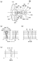
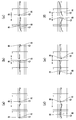
- FIG. 1 is an explanatory diagram of a wide-angle lens according to Example 1 of the present invention.
- FIGS. 1 (a), (b), (c), and (d) are explanatory diagrams showing the lens configuration, astigmatism and It is explanatory drawing which shows the simulation result of a distortion, explanatory drawing which shows the simulation result of spherical aberration, and explanatory drawing which shows the simulation result of lateral chromatic aberration.
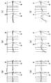
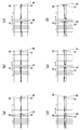
- FIG. 2 is an explanatory diagram showing the simulation results of lateral aberration at each angle of view of the wide-angle lens according to Example 1 of the present invention, and FIG.
- each of the surfaces 1 to 12 is shown in parentheses, and “*” is attached to the aspherical surface.
- the aberrations the aberrations of red light R (wavelength 656 nm), green light G (wavelength 588 nm), and blue light B (wavelength 486 nm) are shown.
- S is added to the sagittal characteristic
- T is added to the tangential characteristic. The same applies to FIGS. 3, 5, 7, and 9, which will be described later.
- the wide-angle lens 100 to which the present invention is applied has a horizontal angle of view of 130 ° or more, and the first lens 110, the second lens 120, the first lens from the object side toward the image side. It has a five-group six-lens configuration including three lenses 130, a fourth lens 140, a diaphragm 190, and a cemented lens 170 (fifth lens 150 and sixth lens 160).
- a filter 181 and an image sensor 186 are arranged on the image side with respect to the cemented lens 170.
- the first first lens 110 from the object side is a meniscus negative plastic lens or glass lens having a convex surface facing the object side and a concave surface facing the image side.
- the second lens 120 second from the object side is a plastic lens having a negative power with a concave surface facing the image side, and at least one of the lens surface on the object side and the lens surface on the image side is an aspherical surface.
- the third third lens 130 from the object side is a plastic lens having a negative power with the concave surface facing the object side, and at least one of the object-side lens surface and the image-side lens surface is an aspherical surface.
- the fourth lens 140 fourth from the object side is a plastic lens or glass lens having a positive power with the convex surface facing the image side.
- the fifth lens 150 which is the fifth lens from the object side
- the sixth lens 160 which is the sixth lens from the object side
- a diaphragm 190 is disposed between the fourth lens 140 and the cemented lens 170.
- Each configuration of the wide-angle lens 100 configured as described above is as shown in Table 1, and the following items of the wide-angle lens 100 are shown in the upper column of Table 1.
- Focal length of third lens 130 f 3
- Radius of curvature of the image-side lens surface of the fifth lens 150 and the object-side lens surface of the sixth lens 160 r 52 ⁇ 61
- Focal length of the fifth lens 150 f 5
- Table 1 the following items of the wide-angle lens 100 are shown.
- Minimum value of tangent angle ⁇ of the image side lens surface of first lens 110 ⁇ min
- the tangent angle ⁇ means an angle formed by the tangent to the lens surface on the image side of the first lens 110 and the optical axis L, and the minimum value ⁇ min of the tangent angle ⁇ is the image side of the first lens 110 on the image side.
- Table 1 also shows each configuration of the wide-angle lens 100 of Examples 2 to 5, which will be described later, in addition to the configuration of the wide-angle lens 100 of this example (Example 1).
- the unit of the focal length in Table 1 is mm.
- the effective focal length f and the focal length f 3 of the third lens 130 have the following relationship:
- F 5 is the following relationship:
- the Abbe number of the third lens 130 is ⁇ 3
- the Abbe number ⁇ 3 has the following relationship ⁇ 3 > 50. Meet.
- the minimum value ⁇ min of the tangent angle ⁇ is 20 ° or more, so the tangent to the lens surface (surface 2) on the image side of the first lens 110 forms the optical axis L.
- the angle (tangent angle ⁇ ) is the following relationship ⁇ > 20 ° at any position on the image-side lens surface (surface 2) of the first lens 110.
- Table 2 shows a specific configuration of the wide-angle lens 100 according to Example 1 of the present invention.
- Effective focal length f Effective Focal Length of the entire lens system Distance between objects (Total Track)
- F value of the entire lens system (Image Space F / #) Max.
- the lower column of Table 2 shows the aspheric coefficients A4 to A10 when the shape of the aspheric surface is expressed by the following formula (Equation 1).
- Equation 1 the axis in the optical axis L direction is z
- the height in the direction perpendicular to the optical axis L is r
- the cone coefficient is k.
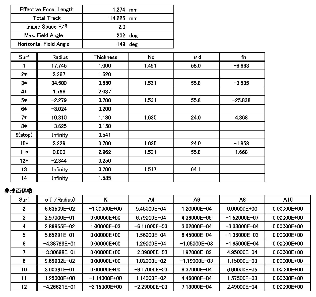
- the unit of curvature radius, thickness, and focal length are all mm. The same applies to Tables 3 to 6 described later.
- the wide-angle lens 100 of this example has a horizontal field angle of 192 °.
- the first lens 110 is a meniscus negative glass lens having a convex surface facing the object side and a concave surface facing the image side, and the object-side lens surface (surface 1). Both the image-side lens surface (surface 2) are spherical.
- the second lens 120 is a meniscus negative plastic lens having a convex surface facing the object side and a concave surface facing the image side.
- the second lens 120 has an object side lens surface (surface 3) and an image side lens surface (surface). Both of 4) are aspherical.
- the third lens 130 is a meniscus negative plastic lens having a concave surface facing the object side and a convex surface facing the image side, and the lens surface (surface 5) on the object side is an aspherical surface.
- the lens surface (surface 6) is a spherical surface.
- the fourth lens 140 is a glass lens having a convex surface facing the object side and a convex surface facing the image side, and both the object-side lens surface (surface 7) and the image-side lens surface (surface 8) are spherical surfaces. .
- the fifth lens 150 is a plastic lens having a negative power with the convex surface facing the object side and the concave surface facing the image side.
- the fifth lens 150 has a lens surface (surface 10) on the object side and a lens surface (surface 11) on the image side. Both are aspherical.
- the sixth lens 160 is a plastic lens having a convex surface facing the object side and a convex surface facing the image side, and both the lens surface (surface 11) on the object side and the lens surface (surface 12) on the image side are aspherical. is there.
- the lens surface on the image side of the fifth lens 150 and the lens surface on the object side of the sixth lens 160 are cemented to form a cemented lens 170 having positive power.
- the wide-angle lens 100 of this example includes the third lens 130 having negative power in addition to the two lenses having negative power (the first lens 110 and the second lens 120).
- the negative power of the first lens 110 and the second lens 120 can be supplemented by the third lens 130. Therefore, the angle (tangent angle ⁇ ) formed by the tangent to the concave surface on the image side of the first lens 110 and the second lens 120 with respect to the optical axis L can be increased. Cheap. Therefore, the cost of the first lens 110 and the second lens 120 can be reduced.
- the minimum value ⁇ min of the tangent angle ⁇ with respect to the image-side lens surface (surface 2) of the first lens 110 is 38.0 °, and in the image-side lens surface (surface 2) of the first lens 110, The tangent angle ⁇ is a value exceeding 20 ° even at this point. For this reason, since the 1st lens 110 has a shape which is easy to manufacture, the cost of the 1st lens 110 can be reduced.
- the third lens 130 is an aspherical lens.
- of the ratio between the effective focal length f and the focal length f 3 of the third lens 130 is 0.135, which is less than 0.2. Therefore, as shown in FIGS. 1B, 1C, and 2, astigmatism, distortion, spherical aberration, and coma (lateral aberration) can be reduced, and the F value is set brighter. Even in this case, the aberration can be corrected.
- the third lens 130 is made of a glass lens, it is possible to suppress a decrease in resolution due to a temperature change.
- is 0.401 and is less than 0.5.
- the Abbe number ⁇ 3 of the third lens 130 is 55.8, which is 50 or more. For this reason, chromatic aberration can be reduced as shown in FIG.
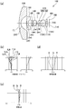
- FIG. 3 is an explanatory diagram of a wide-angle lens according to Example 2 of the present invention
- FIGS. 3A, 3B, 3C, and 3D are explanatory diagrams showing the lens configuration, astigmatism and It is explanatory drawing which shows the simulation result of a distortion
- explanatory drawing which shows the simulation result of spherical aberration
- explanatory drawing which shows the simulation result of lateral chromatic aberration
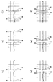
- FIG. 4 is an explanatory diagram showing the results of simulation of lateral aberration at each angle of view of the wide-angle lens according to Example 2 of the present invention
- FIG. 4 (a), (b), (c), (d), ( e) and (f) are explanatory diagrams of lateral aberration at an angle of view of 0 °, explanatory diagrams of lateral aberration at 30.86 °, explanatory diagrams of lateral aberration at 56.01 °, and lateral aberration at 77.16 °. It is explanatory drawing, explanatory drawing of lateral aberration in 97.26 degrees, and explanatory drawing of lateral aberration in 103.35 degrees.
- FIG. 4 collectively shows aberrations of red light R (wavelength 656 nm), green light G (wavelength 588 nm), and blue light B (wavelength 486 nm).
- the wide-angle lens 100 of the present example is also the first lens 110, the second lens 120, the third lens 130, and the fourth lens from the object side toward the image side, as in the first embodiment. 140, a diaphragm 190, and a cemented lens 170 (fifth lens 150 and sixth lens 160). A filter 181 and an image sensor 186 are arranged on the image side with respect to the cemented lens 170.
- Table 3 Each configuration of the wide-angle lens 100 configured as described above is as shown in Table 3.
- the wide-angle lens 100 of this example has a horizontal field angle of 195 °.
- the first lens 110 is a meniscus negative plastic lens having a convex surface facing the object side and a concave surface facing the image side, and the object-side lens surface (surface 1). Is a spherical surface, and the image-side lens surface (surface 2) is an aspherical surface.
- the second lens 120 is a plastic lens having a negative power with the concave surface facing the object side and the concave surface facing the image side.
- the second lens 120 includes a lens surface (surface 3) on the object side and a lens surface (surface 4) on the image side. Both are aspherical.
- the third lens 130 is a plastic lens having negative power with a concave surface facing the object side and a convex surface facing the image side.
- the third lens 130 includes a lens surface (surface 5) on the object side and a lens surface (surface 6) on the image side. Both are aspherical.
- the fourth lens 140 is a plastic lens having a convex surface facing the object side and a convex surface facing the image side, and both the lens surface (surface 7) on the object side and the lens surface (surface 8) on the image side are aspherical. is there.
- the fifth lens 150 is a plastic lens having a convex surface on the object side and a concave surface on the image side, and both the lens surface (surface 10) on the object side and the lens surface (surface 11) on the image side are aspherical. is there.
- the sixth lens 160 is a plastic lens having a convex surface facing the object side and a convex surface facing the image side, and both the lens surface (surface 11) on the object side and the lens surface (surface 12) on the image side are aspherical. is there.
- the lens surface on the image side of the fifth lens 150 and the lens surface on the object side of the sixth lens 160 are cemented to form a cemented lens 170 having positive power.
- the third lens having the negative power is used. Since the lens 130 is provided, the angle (tangent angle ⁇ ) formed by the tangent to the concave surface on the image side of the first lens 110 and the second lens 120 with the optical axis L can be increased.
- the minimum value ⁇ min of the tangent angle ⁇ with respect to the image side lens surface (surface 2) of the first lens 110 is 24.2 °, and the image side lens surface (surface 2) of the first lens 110 is The tangent angle ⁇ is a value exceeding 20 ° even at this point. For this reason, since the 1st lens 110 has a shape which is easy to manufacture, the cost of the 1st lens 110 can be reduced.
- the plastic lens such as the third lens 130 being an aspherical lens
- all surfaces except the lens surface (surface 1) on the object side of the first lens 110 are aspherical.
- of the ratio between the effective focal length f and the focal length f 3 of the third lens 130 is 0.027, which is less than 0.2.
- astigmatism, distortion, spherical aberration, and coma aberration (lateral aberration) can be reduced, and the F value is set brighter. Even in this case, the aberration can be corrected.
- is 0.410 and less than 0.5.
- the Abbe number ⁇ 3 of the third lens 130 is 55.8, which is 50 or more. For this reason, as shown in FIG. 3D, chromatic aberration can be reduced.
- FIG. 5 is an explanatory diagram of a wide-angle lens according to Example 3 of the present invention.
- FIGS. 5 (a), (b), (c), and (d) are explanatory diagrams showing the lens configuration, astigmatism and It is explanatory drawing which shows the simulation result of a distortion, explanatory drawing which shows the simulation result of spherical aberration, and explanatory drawing which shows the simulation result of lateral chromatic aberration.
- FIGS. 6A and 6B are explanatory views showing the results of simulation of lateral aberration at each angle of view of the wide-angle lens according to Example 3 of the present invention.
- FIGS. 6A, 6B, 6C, 6D, and 6D are provided.
- e) and (f) are explanatory diagrams of lateral aberration at an angle of view of 0 °, explanatory diagrams of lateral aberration at 24.17 °, explanatory diagrams of lateral aberration at 43.79 °, and lateral aberrations at 60.51 °. It is explanatory drawing, explanatory drawing of lateral aberration in 75.53 degrees, and explanatory drawing of lateral aberration in 89.24 degrees.
- the wide-angle lens 100 of the present example also has the first lens 110, the second lens 120, the third lens 130, and the fourth lens from the object side toward the image side as in the first embodiment. 140, a diaphragm 190, and a cemented lens 170 (fifth lens 150 and sixth lens 160). A filter 181 and an image sensor 186 are arranged on the image side with respect to the cemented lens 170.
- Table 4 Each configuration of the wide-angle lens 100 configured as described above is as shown in Table 4.
- the wide-angle lens 100 of this example has a horizontal field angle of 151 °.
- the first lens 110 is a meniscus negative glass lens having a convex surface facing the object side and a concave surface facing the image side, and the object-side lens surface (surface 1). Both the image-side lens surface (surface 2) are spherical.
- the second lens 120 is a plastic lens having a negative power with the concave surface facing the object side and the concave surface facing the image side.
- the second lens 120 includes a lens surface (surface 3) on the object side and a lens surface (surface 4) on the image side. Both are aspherical.
- the third lens 130 is a plastic lens having a negative power with the concave surface facing the object side and the concave surface facing the image side.
- the lens surface (surface 5) on the object side is an aspheric surface, and the lens surface on the image side. (Surface 6) is a spherical surface.
- the fourth lens 140 is a glass lens having a convex surface facing the object side and a convex surface facing the image side, and both the object-side lens surface (surface 7) and the image-side lens surface (surface 8) are spherical surfaces. .
- the fifth lens 150 is a plastic lens having a negative power with the convex surface facing the object side and the concave surface facing the image side.
- the fifth lens 150 has a lens surface (surface 10) on the object side and a lens surface (surface 11) on the image side. Both are aspherical.
- the sixth lens 160 is a plastic lens having a convex surface facing the object side and a convex surface facing the image side, and both the lens surface (surface 11) on the object side and the lens surface (surface 12) on the image side are aspherical. is there.
- the lens surface on the image side of the fifth lens 150 and the lens surface on the object side of the sixth lens 160 are cemented to form a cemented lens 170 having positive power.
- the third lens having the negative power is used. Since the lens 130 is provided, the angle (tangent angle ⁇ ) formed by the tangent to the concave surface on the image side of the first lens 110 and the second lens 120 with the optical axis L can be increased.
- the minimum value ⁇ min of the tangent angle ⁇ with respect to the image-side lens surface (surface 2) of the first lens 110 is 25.4 °, and the image-side lens surface (surface 2) of the first lens 110 is The tangent angle ⁇ is a value exceeding 20 ° even at this point. For this reason, since the 1st lens 110 has a shape which is easy to manufacture, the cost of the 1st lens 110 can be reduced.
- the third lens 130 is an aspherical lens.
- of the ratio between the effective focal length f and the focal length f 3 of the third lens 130 is 0.085 and less than 0.2. Therefore, as shown in FIGS. 5B, 5C, and 6, astigmatism, distortion, spherical aberration, and coma (lateral aberration) can be reduced, and the F value is set brighter. Even in this case, the aberration can be corrected.
- the fourth lens 140 is made of a glass lens, it is possible to suppress a decrease in resolution due to a temperature change.
- is 0.454 and less than 0.5.
- the Abbe number ⁇ 3 of the third lens 130 is 55.8, which is 50 or more. For this reason, chromatic aberration can be reduced as shown in FIG.
- FIG. 7 is an explanatory diagram of a wide-angle lens according to Example 4 of the present invention
- FIGS. 7A, 7B, 7C, and 7D are explanatory diagrams showing the lens configuration, astigmatism and It is explanatory drawing which shows the simulation result of a distortion
- explanatory drawing which shows the simulation result of spherical aberration
- explanatory drawing which shows the simulation result of lateral chromatic aberration
- FIG. 8 is an explanatory diagram showing the simulation results of lateral aberration at each angle of view of the wide-angle lens according to Example 4 of the present invention
- the wide-angle lens 100 of the present example also has the first lens 110, the second lens 120, the third lens 130, and the fourth lens from the object side toward the image side, as in the first embodiment. It has a five-group six-lens configuration including a lens 140, a diaphragm 190, and a cemented lens 170 (fifth lens 150 and sixth lens 160). A filter 181 and an image sensor 186 are arranged on the image side with respect to the cemented lens 170.
- Each configuration of the wide-angle lens 100 configured as described above is as shown in Table 5.
- the wide angle lens 100 of this example has a horizontal field angle of 161 °.
- the first lens 110 is a meniscus negative plastic lens having a convex surface facing the object side and a concave surface facing the image side, and the object-side lens surface (surface 1). Is a spherical surface, and the image-side lens surface (surface 2) is an aspherical surface.
- the second lens 120 is a plastic lens having negative power with a convex surface facing the object side and a concave surface facing the image side.
- the second lens 120 has a lens surface (surface 3) on the object side and a lens surface (surface 4) on the image side. Both are aspherical.
- the third lens 130 is a negative meniscus plastic lens having a concave surface on the object side and a convex surface on the image side, and both the object-side lens surface (surface 5) and the image-side lens surface (surface 6). Is an aspherical surface.
- the fourth lens 140 is a plastic lens having a convex surface facing the object side and a convex surface facing the image side, and both the lens surface (surface 7) on the object side and the lens surface (surface 8) on the image side are aspherical. is there.
- the fifth lens 150 is a plastic lens having a convex surface on the object side and a concave surface on the image side, and both the lens surface (surface 10) on the object side and the lens surface (surface 11) on the image side are aspherical. is there.
- the sixth lens 160 is a plastic lens having a convex surface facing the object side and a convex surface facing the image side, and both the lens surface (surface 11) on the object side and the lens surface (surface 12) on the image side are aspherical. is there.
- the lens surface on the image side of the fifth lens 150 and the lens surface on the object side of the sixth lens 160 are cemented to form a cemented lens 170 having positive power.
- the third lens having the negative power is used. Since the lens 130 is provided, the angle (tangent angle ⁇ ) formed by the tangent to the concave surface on the image side of the first lens 110 and the second lens 120 with the optical axis L can be increased.
- the minimum value ⁇ min of the tangent angle ⁇ with respect to the image side lens surface (surface 2) of the first lens 110 is 24.2 °, and the image side lens surface (surface 2) of the first lens 110 is The tangent angle ⁇ is a value exceeding 20 ° even at this point. For this reason, since the 1st lens 110 has a shape which is easy to manufacture, the cost of the 1st lens 110 can be reduced.
- the plastic lens such as the third lens 130 being an aspherical lens
- all surfaces except the lens surface (surface 1) on the object side of the first lens 110 are aspherical.
- of the ratio between the effective focal length f and the focal length f 3 of the third lens 130 is 0.061, which is less than 0.2. Therefore, as shown in FIGS. 7B, 7C, and 8, astigmatism, distortion, spherical aberration, and coma (lateral aberration) can be reduced, and the F value is set brighter. Even in this case, the aberration can be corrected.
- is 0.418 and is less than 0.5.
- the Abbe number ⁇ 3 of the third lens 130 is 55.8, which is 50 or more. For this reason, as shown in FIG. 7D, chromatic aberration can be reduced.
- FIG. 9 is an explanatory diagram of a wide-angle lens according to Example 5 of the present invention.
- FIGS. 9A, 9B, 9C, and 9D are explanatory diagrams showing the lens configuration, astigmatism and It is explanatory drawing which shows the simulation result of a distortion, explanatory drawing which shows the simulation result of spherical aberration, and explanatory drawing which shows the simulation result of lateral chromatic aberration.
- FIG. 10 is an explanatory diagram showing the simulation results of lateral aberration at each angle of view of the wide-angle lens according to Example 5 of the present invention, and FIGS.
- the wide-angle lens 100 of the present example also has a first lens 110, a second lens 120, a third lens 130, and a fourth lens from the object side toward the image side, as in the first embodiment. 140, a diaphragm 190, and a cemented lens 170 (fifth lens 150 and sixth lens 160).
- a filter 181 and an image sensor 186 are arranged on the image side with respect to the cemented lens 170.
- Table 6 Each configuration of the wide-angle lens 100 configured as described above is as shown in Table 6.
- the wide-angle lens 100 of this example has a horizontal field angle of 149 °.
- the first lens 110 is a meniscus negative plastic lens having a convex surface on the object side and a concave surface on the image side, and the lens surface (surface 1) on the object side is It is spherical and the image side lens surface (surface 2) is aspheric.
- the second lens 120 is a plastic lens having negative power with a convex surface facing the object side and a concave surface facing the image side.
- the second lens 120 has a lens surface (surface 3) on the object side and a lens surface (surface 4) on the image side. Both are aspherical.
- the third lens 130 is a negative meniscus plastic lens having a concave surface on the object side and a convex surface on the image side, and both the object-side lens surface (surface 5) and the image-side lens surface (surface 6). Is an aspherical surface.
- the fourth lens 140 is a plastic lens having a convex surface facing the object side and a convex surface facing the image side, and both the lens surface (surface 7) on the object side and the lens surface (surface 8) on the image side are aspherical. is there.
- the fifth lens 150 is a plastic lens having a convex surface on the object side and a concave surface on the image side, and both the lens surface (surface 10) on the object side and the lens surface (surface 11) on the image side are aspherical. is there.
- the sixth lens 160 is a plastic lens having a convex surface facing the object side and a convex surface facing the image side, and both the lens surface (surface 11) on the object side and the lens surface (surface 12) on the image side are aspherical. is there.
- the lens surface on the image side of the fifth lens 150 and the lens surface on the object side of the sixth lens 160 are cemented to form a cemented lens 170 having positive power.
- the third lens having the negative power is used. Since the lens 130 is provided, the angle (tangent angle ⁇ ) formed by the tangent to the concave surface on the image side of the first lens 110 and the second lens 120 with the optical axis L can be increased.
- the minimum value ⁇ min of the tangent angle ⁇ with respect to the image side lens surface (surface 2) of the first lens 110 is 45.0 °.
- the tangent angle ⁇ is a value exceeding 20 ° even at this point. For this reason, since the 1st lens 110 has a shape which is easy to manufacture, the cost of the 1st lens 110 can be reduced.
- the plastic lens such as the third lens 130 being an aspherical lens
- all surfaces except the lens surface (surface 1) on the object side of the first lens 110 are aspherical.
- of the ratio between the effective focal length f and the focal length f 3 of the third lens 130 is 0.049, which is less than 0.2.
- astigmatism, distortion, spherical aberration, and coma aberration (lateral aberration) can be reduced, and the F value is set brighter. Even in this case, the aberration can be corrected.
- is 0.431 and is less than 0.5.
- the Abbe number ⁇ 3 of the third lens 130 is 55.8, which is 50 or more. For this reason, as shown in FIG. 9D, chromatic aberration can be reduced.
Landscapes
- Physics & Mathematics (AREA)
- General Physics & Mathematics (AREA)
- Optics & Photonics (AREA)
- Lenses (AREA)
Abstract
Description
物体側から第1番目の第1レンズは、物体側に凸面を向け、像側に凹面を向けた負のパワーを有するプラスチックレンズまたはガラスレンズであり、
物体側から第2番目の第2レンズは、像側に凹面を向けた負のパワーを有するプラスチックレンズで、物体側のレンズ面および像側のレンズ面の少なくとも一方が非球面であり、
物体側から第3番目の第3レンズは、物体側に凹面を向けた負のパワーを有するプラスチックレンズで、物体側のレンズ面および像側のレンズ面の少なくとも一方が非球面であり、
物体側から第4番目の第4レンズは、像側に凸面を向けた正のパワーを有するプラスチックレンズまたはガラスレンズであり、
物体側から第5番目の第5レンズ、および物体側から第6番目の第6レンズは、双方がプラスチックレンズで、正のパワーを有する接合レンズを構成しており、
前記第4レンズと前記接合レンズとの間に絞りが配置され、
有効焦点距離をfとし、前記第3レンズの焦点距離をf3としたとき、有効焦点距離fおよび焦点距離f3は、以下の関係
|f/f3| < 0.2
を満たすことを特徴とする。
|r52・61/f5| < 0.5
を満たすことが好ましい。かかる構成によれば、色収差を低減することができる。
ν3 > 50
を満たすことが好ましい。かかる構成によれば、色収差を低減することができる。
θ > 20°
を満たすことが好ましい。かかる構成によれば、第1レンズの像側の凹面に対する接線が光軸となす角度(接線角)を大きくすることができ、かかる凹面の形状であれば、レンズを製造しやすい。従って、第1レンズのコストを低減することができる。
|f/f3| < 0.2
を満たしているので、非点収差やコマ収差(横収差)を低減することができるとともに、F値を明るく設定した場合でも、収差の補正を行うことができる。
110・・第1レンズ
120・・第2レンズ
130・・第3レンズ
140・・第4レンズ
150・・第5レンズ
160・・第6レンズ
170・・接合レンズ
190・・絞り
(概略構成)
図1は、本発明の実施例1に係る広角レンズの説明図であり、図1(a)、(b)、(c)、(d)は、レンズ構成を示す説明図、非点収差とディストーションのシミュレーション結果を示す説明図、球面収差のシミュレーション結果を示す説明図、および倍率色収差のシミュレーション結果を示す説明図である。図2は、本発明の実施例1に係る広角レンズの各画角における横収差のシミュレーション結果を示す説明図であり、図2(a)、(b)、(c)、(d)、(e)は、画角が0°における横収差の説明図、26.91°における横収差の説明図、49.78°における横収差の説明図、71.63°における横収差の説明図、および96.01°における横収差の説明図である。ディストーションとは、撮像中央部と周辺部における像の変化比率を示し、ディストーションをあらわす数値の絶対値が小さいほど、高精度なレンズといえる。

物像間距離=TTL
第3レンズ130の焦点距離=f3
第5レンズ150の像側のレンズ面、および第6レンズ160の物体側のレンズ面の曲率半径=r52・61
第5レンズ150の焦点距離=f5
また、表1の下欄には、広角レンズ100の以下の項目が示されている。
第3レンズ130のアッベ数=ν3
有効焦点距離と第3レンズ130の焦点距離との比=f/f3
曲率半径r52・61と第5レンズ150の焦点距離との比の絶対値=|r52・61/f5|
第1レンズ110の像側のレンズ面の接線角θの最小値=θmin
ここで、接線角θとは、第1レンズ110の像側のレンズ面に対する接線が光軸Lとなす角度を意味し、接線角θの最小値θminとは、第1レンズ110の像側のレンズ面の最も外周側に対する接線が光軸Lとなす角度に相当する。なお、表1には、本例(実施例1)の広角レンズ100の各構成の他、後述する実施例2~5の広角レンズ100の各構成も示してある。また、表1における焦点距離等の単位はmmである。
|f/f3| < 0.2
を満している。
|r52・61/f5| < 0.5
を満たしている。
ν3 > 50
を満たしている。
θ > 20°
を満たしている。
本発明の実施例1に係る広角レンズ100の具体的な構成を表2に示してある。
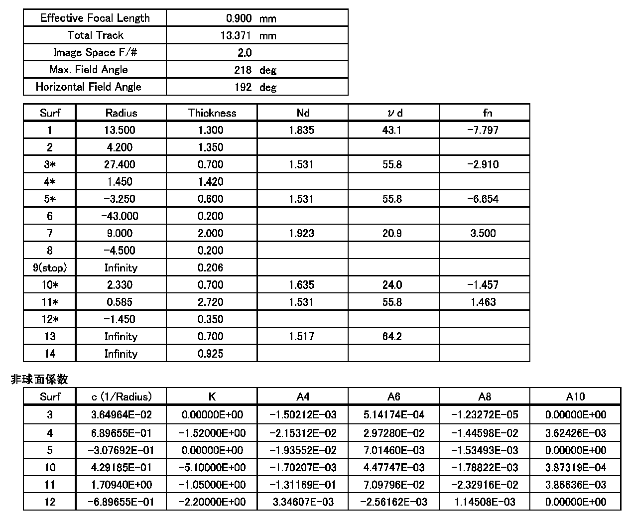
レンズ系全体の有効焦点距離f(Effective Focal Length)
物像間距離(Total Track)
レンズ系全体のF値(Image Space F/#)
最大画角(Max. Field Angle)
水平画角(Horizontal Field Angle)
が示されている。
曲率半径(Radius)
厚さ(Thickness)
屈折率Nd
アッベ数νd
焦点距離fn
が示されている。

図3は、本発明の実施例2に係る広角レンズの説明図であり、図3(a)、(b)、(c)、(d)は、レンズ構成を示す説明図、非点収差とディストーションのシミュレーション結果を示す説明図、球面収差のシミュレーション結果を示す説明図、および倍率色収差のシミュレーション結果を示す説明図である。図4は、本発明の実施例2に係る広角レンズの各画角における横収差のシミュレーション結果を示す説明図であり、図4(a)、(b)、(c)、(d)、(e)、(f)は、画角が0°における横収差の説明図、30.86°における横収差の説明図、56.01°における横収差の説明図、77.16°における横収差の説明図、97.26°における横収差の説明図、および103.35°における横収差の説明図である。なお、図4には、赤色光R(波長656nm)、緑色光G(波長588nm)、青色光B(波長486nm)の収差をまとめて示してある。
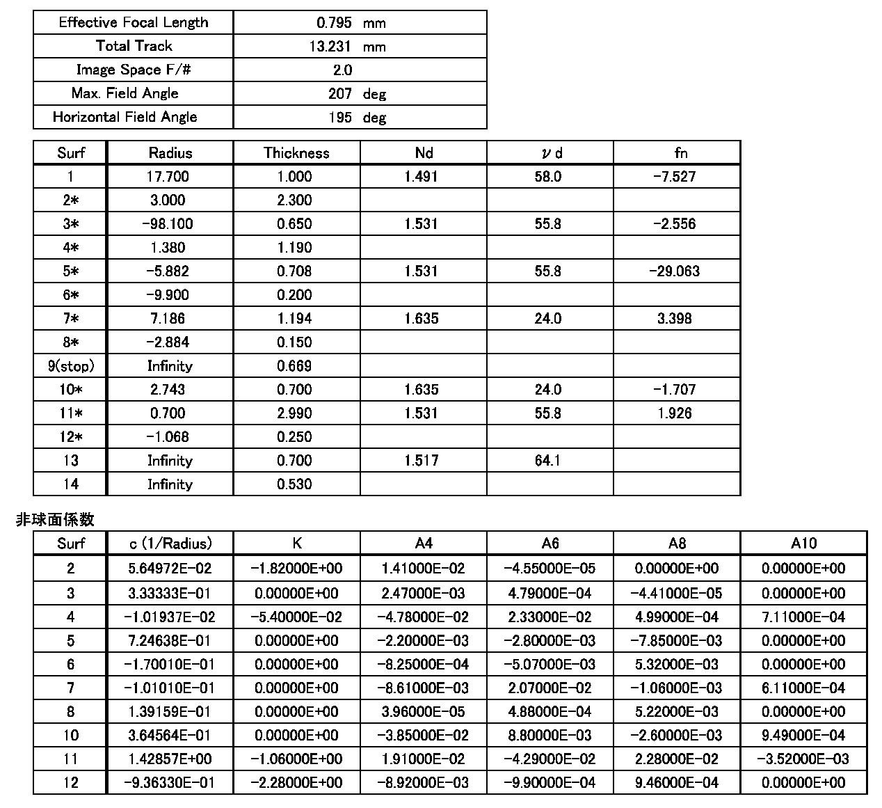
図5は、本発明の実施例3に係る広角レンズの説明図であり、図5(a)、(b)、(c)、(d)は、レンズ構成を示す説明図、非点収差とディストーションのシミュレーション結果を示す説明図、球面収差のシミュレーション結果を示す説明図、および倍率色収差のシミュレーション結果を示す説明図である。図6は、本発明の実施例3に係る広角レンズの各画角における横収差のシミュレーション結果を示す説明図であり、図6(a)、(b)、(c)、(d)、(e)、(f)は、画角が0°における横収差の説明図、24.17°における横収差の説明図、43.79°における横収差の説明図、60.51°における横収差の説明図、75.53°における横収差の説明図、および89.24°における横収差の説明図である。
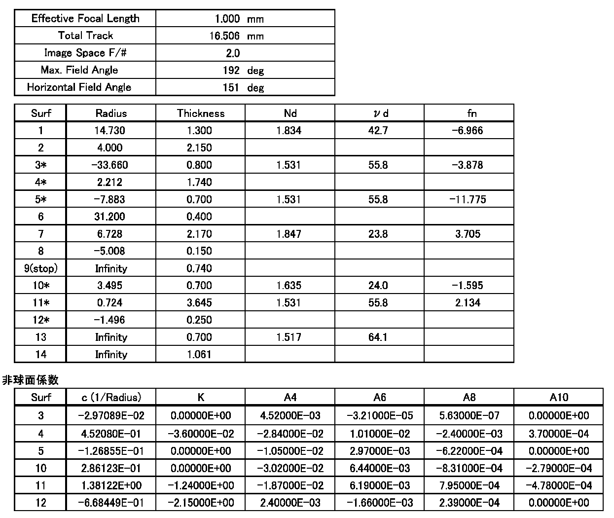
図7は、本発明の実施例4に係る広角レンズの説明図であり、図7(a)、(b)、(c)、(d)は、レンズ構成を示す説明図、非点収差とディストーションのシミュレーション結果を示す説明図、球面収差のシミュレーション結果を示す説明図、および倍率色収差のシミュレーション結果を示す説明図である。図8は、本発明の実施例4に係る広角レンズの各画角における横収差のシミュレーション結果を示す説明図であり、図8(a)、(b)、(c)、(d)、(e)、(f)は、画角が0°における横収差の説明図、24.54°における横収差の説明図、46.42°における横収差の説明図、64.64°における横収差の説明図、80.45°における横収差の説明図、および94.93°における横収差の説明図である。

図9は、本発明の実施例5に係る広角レンズの説明図であり、図9(a)、(b)、(c)、(d)は、レンズ構成を示す説明図、非点収差とディストーションのシミュレーション結果を示す説明図、球面収差のシミュレーション結果を示す説明図、および倍率色収差のシミュレーション結果を示す説明図である。図10は、本発明の実施例5に係る広角レンズの各画角における横収差のシミュレーション結果を示す説明図であり、図10(a)、(b)、(c)、(d)、(e)、(f)は、画角が0°における横収差の説明図、19.82°における横収差の説明図、38.39°における横収差の説明図、56.21°における横収差の説明図、74.56°における横収差の説明図、および97.34°における横収差の説明図である。
Claims (6)
- 水平画角が130°以上であって、5群6枚のレンズ構成を有し、
物体側から第1番目の第1レンズは、物体側に凸面を向け、像側に凹面を向けた負のパワーを有するプラスチックレンズまたはガラスレンズであり、
物体側から第2番目の第2レンズは、像側に凹面を向けた負のパワーを有するプラスチックレンズで、物体側のレンズ面および像側のレンズ面の少なくとも一方が非球面であり、
物体側から第3番目の第3レンズは、物体側に凹面を向けた負のパワーを有するプラスチックレンズで、物体側のレンズ面および像側のレンズ面の少なくとも一方が非球面であり、
物体側から第4番目の第4レンズは、像側に凸面を向けた正のパワーを有するプラスチックレンズまたはガラスレンズであり、
物体側から第5番目の第5レンズ、および物体側から第6番目の第6レンズは、双方がプラスチックレンズで、正のパワーを有する接合レンズを構成しており、
前記第4レンズと前記接合レンズとの間に絞りが配置され、
有効焦点距離をfとし、前記第3レンズの焦点距離をf3としたとき、有効焦点距離fおよび焦点距離f3は、以下の関係
|f/f3| < 0.2
を満たすことを特徴とする広角レンズ。 - 前記第5レンズの像側のレンズ面、および前記第6レンズの物体側のレンズ面の曲率半径をr52・61とし、前記第5レンズの焦点距離をf5としたとき、曲率半径r52・61および焦点距離f5は、以下の関係
|r52・61/f5| < 0.5
を満たすことを特徴とする請求項1に記載の広角レンズ。 - 前記第3レンズのアッベ数をν3としたとき、アッベ数ν3は、以下の関係
ν3 > 50
を満たすことを特徴とする請求項1または2に記載の広角レンズ。 - 前記第1レンズの像側のレンズ面に対する接線が光軸と成す角度をθとしたとき、角度θは、以下の関係
θ > 20°
を満たすことを特徴とする請求項1乃至3の何れか一項に記載の広角レンズ。 - 前記第4レンズはガラスレンズであることを特徴とする請求項1乃至4の何れか一項に記載の広角レンズ。
- 前記プラスチックレンズのレンズ面うち、前記第1レンズの物体側のレンズ面以外のレンズ面は、全て非球面であることを特徴とする請求項1乃至5の何れか一項に記載の広角レンズ。
Priority Applications (2)
| Application Number | Priority Date | Filing Date | Title |
|---|---|---|---|
| CN201480043146.2A CN105452928A (zh) | 2013-08-09 | 2014-08-04 | 广角透镜 |
| US14/911,147 US9904033B2 (en) | 2013-08-09 | 2014-08-04 | Wide-angle lens |
Applications Claiming Priority (2)
| Application Number | Priority Date | Filing Date | Title |
|---|---|---|---|
| JP2013166339A JP2015034922A (ja) | 2013-08-09 | 2013-08-09 | 広角レンズ |
| JP2013-166339 | 2013-08-09 |
Publications (1)
| Publication Number | Publication Date |
|---|---|
| WO2015020006A1 true WO2015020006A1 (ja) | 2015-02-12 |
Family
ID=52461338
Family Applications (1)
| Application Number | Title | Priority Date | Filing Date |
|---|---|---|---|
| PCT/JP2014/070499 Ceased WO2015020006A1 (ja) | 2013-08-09 | 2014-08-04 | 広角レンズ |
Country Status (4)
| Country | Link |
|---|---|
| US (1) | US9904033B2 (ja) |
| JP (1) | JP2015034922A (ja) |
| CN (1) | CN105452928A (ja) |
| WO (1) | WO2015020006A1 (ja) |
Cited By (2)
| Publication number | Priority date | Publication date | Assignee | Title |
|---|---|---|---|---|
| EP3226053A1 (en) * | 2016-03-31 | 2017-10-04 | Nidec Sankyo Corporation | Wide angle lens |
| TWI702435B (zh) * | 2020-05-22 | 2020-08-21 | 大陸商玉晶光電(廈門)有限公司 | 光學成像鏡頭 |
Families Citing this family (23)
| Publication number | Priority date | Publication date | Assignee | Title |
|---|---|---|---|---|
| WO2015107579A1 (ja) * | 2014-01-20 | 2015-07-23 | パナソニックIpマネジメント株式会社 | 単焦点レンズ系、カメラ及び自動車 |
| JP6393872B2 (ja) * | 2014-08-27 | 2018-09-26 | カンタツ株式会社 | 撮像レンズ |
| JP6539120B2 (ja) * | 2015-06-11 | 2019-07-03 | 日本電産サンキョー株式会社 | 車載カメラ用レンズユニット |
| CN104991331B (zh) * | 2015-08-06 | 2017-12-22 | 浙江舜宇光学有限公司 | 超广角镜头 |
| TWI582457B (zh) | 2016-04-20 | 2017-05-11 | 大立光電股份有限公司 | 取像光學系統鏡組、取像裝置及電子裝置 |
| JP6845484B2 (ja) * | 2016-06-06 | 2021-03-17 | コニカミノルタ株式会社 | 撮像光学系、レンズユニット及び撮像装置 |
| US10634885B2 (en) | 2016-07-25 | 2020-04-28 | Nidec Sankyo Corporation | Wide-angle lens |
| JP6769863B2 (ja) * | 2016-09-30 | 2020-10-14 | 日本電産サンキョー株式会社 | 広角レンズ |
| CN107884913B (zh) * | 2016-09-30 | 2020-05-19 | 日本电产三协株式会社 | 广角镜头 |
| KR101832627B1 (ko) * | 2016-11-25 | 2018-02-26 | 삼성전기주식회사 | 촬상 광학계 |
| CN108614344B (zh) * | 2016-12-12 | 2023-08-11 | 广西师范大学 | 一种车载广角镜头 |
| TWI613482B (zh) | 2017-01-25 | 2018-02-01 | 大立光電股份有限公司 | 光學影像鏡片系統組、取像裝置及電子裝置 |
| CN114578529B (zh) * | 2017-06-22 | 2024-11-22 | 玉晶光电(厦门)有限公司 | 光学成像镜头 |
| JP2019056786A (ja) | 2017-09-21 | 2019-04-11 | 日本電産サンキョー株式会社 | レンズユニット |
| TWI641865B (zh) | 2017-09-27 | 2018-11-21 | 大立光電股份有限公司 | 光學成像鏡組、取像裝置及電子裝置 |
| CN108107547B (zh) | 2017-10-13 | 2021-12-07 | 玉晶光电(厦门)有限公司 | 光学成像镜头 |
| TWI627469B (zh) * | 2017-10-13 | 2018-06-21 | 玉晶光電股份有限公司 | 光學成像鏡頭 |
| CN108107550A (zh) * | 2017-11-07 | 2018-06-01 | 玉晶光电(厦门)有限公司 | 光学成像镜头 |
| TWI670516B (zh) * | 2018-06-13 | 2019-09-01 | 大立光電股份有限公司 | 攝影光學鏡頭、取像裝置及電子裝置 |
| TWI823882B (zh) * | 2018-12-14 | 2023-12-01 | 光芒光學股份有限公司 | 鏡頭及其製造方法 |
| CN112987236B (zh) * | 2019-12-13 | 2026-01-16 | 日本电产三协株式会社 | 广角透镜 |
| CN117761865B (zh) * | 2023-12-06 | 2025-09-26 | 江西联创电子有限公司 | 光学镜头 |
| CN117348215B (zh) * | 2023-12-06 | 2024-03-29 | 江西联创电子有限公司 | 光学镜头 |
Citations (8)
| Publication number | Priority date | Publication date | Assignee | Title |
|---|---|---|---|---|
| JPH04267212A (ja) * | 1991-02-21 | 1992-09-22 | Copal Co Ltd | 超広角レンズ |
| JPH09304694A (ja) * | 1995-11-07 | 1997-11-28 | Nikon Corp | 投射レンズ系及びそれを備えた投射装置 |
| JP2009063877A (ja) * | 2007-09-07 | 2009-03-26 | Nidec Nissin Corp | 超広角レンズ |
| KR20100136832A (ko) * | 2009-06-19 | 2010-12-29 | (주)위오 | 광각 카메라용 광학계 |
| WO2012008694A1 (en) * | 2010-07-15 | 2012-01-19 | Lg Innotek Co., Ltd. | Super wide angle optical lens system |
| JP2012098724A (ja) * | 2010-10-29 | 2012-05-24 | Kofukin Seimitsu Kogyo (Shenzhen) Yugenkoshi | 超広角レンズ |
| JP2012103319A (ja) * | 2010-11-08 | 2012-05-31 | Optical Logic Inc | 撮像レンズ |
| JP2014085559A (ja) * | 2012-10-25 | 2014-05-12 | Nidec Sankyo Corp | 広角レンズ |
Family Cites Families (2)
| Publication number | Priority date | Publication date | Assignee | Title |
|---|---|---|---|---|
| CN1164033A (zh) * | 1996-03-29 | 1997-11-05 | 三星航空产业株式会社 | 广角摄影镜头系统 |
| TWI485464B (zh) * | 2010-12-30 | 2015-05-21 | Largan Precision Co Ltd | 成像用光學鏡片組 |
-
2013
- 2013-08-09 JP JP2013166339A patent/JP2015034922A/ja active Pending
-
2014
- 2014-08-04 US US14/911,147 patent/US9904033B2/en active Active
- 2014-08-04 CN CN201480043146.2A patent/CN105452928A/zh active Pending
- 2014-08-04 WO PCT/JP2014/070499 patent/WO2015020006A1/ja not_active Ceased
Patent Citations (8)
| Publication number | Priority date | Publication date | Assignee | Title |
|---|---|---|---|---|
| JPH04267212A (ja) * | 1991-02-21 | 1992-09-22 | Copal Co Ltd | 超広角レンズ |
| JPH09304694A (ja) * | 1995-11-07 | 1997-11-28 | Nikon Corp | 投射レンズ系及びそれを備えた投射装置 |
| JP2009063877A (ja) * | 2007-09-07 | 2009-03-26 | Nidec Nissin Corp | 超広角レンズ |
| KR20100136832A (ko) * | 2009-06-19 | 2010-12-29 | (주)위오 | 광각 카메라용 광학계 |
| WO2012008694A1 (en) * | 2010-07-15 | 2012-01-19 | Lg Innotek Co., Ltd. | Super wide angle optical lens system |
| JP2012098724A (ja) * | 2010-10-29 | 2012-05-24 | Kofukin Seimitsu Kogyo (Shenzhen) Yugenkoshi | 超広角レンズ |
| JP2012103319A (ja) * | 2010-11-08 | 2012-05-31 | Optical Logic Inc | 撮像レンズ |
| JP2014085559A (ja) * | 2012-10-25 | 2014-05-12 | Nidec Sankyo Corp | 広角レンズ |
Cited By (3)
| Publication number | Priority date | Publication date | Assignee | Title |
|---|---|---|---|---|
| EP3226053A1 (en) * | 2016-03-31 | 2017-10-04 | Nidec Sankyo Corporation | Wide angle lens |
| CN107272163A (zh) * | 2016-03-31 | 2017-10-20 | 日本电产三协株式会社 | 广角镜头 |
| TWI702435B (zh) * | 2020-05-22 | 2020-08-21 | 大陸商玉晶光電(廈門)有限公司 | 光學成像鏡頭 |
Also Published As
| Publication number | Publication date |
|---|---|
| US9904033B2 (en) | 2018-02-27 |
| US20160187617A1 (en) | 2016-06-30 |
| CN105452928A (zh) | 2016-03-30 |
| JP2015034922A (ja) | 2015-02-19 |
Similar Documents
| Publication | Publication Date | Title |
|---|---|---|
| JP2015034922A (ja) | 広角レンズ | |
| JP6385214B2 (ja) | 広角レンズ | |
| JP6889721B2 (ja) | 広角レンズ | |
| TWI437311B (zh) | 影像拾取鏡組 | |
| TWI448722B (zh) | 成像系統 | |
| TWI417596B (zh) | 廣視角攝影鏡頭 | |
| TWI416197B (zh) | 廣視角攝像鏡頭 | |
| KR101652849B1 (ko) | 렌즈 모듈 | |
| JP6740904B2 (ja) | 撮像レンズおよび撮像装置 | |
| TWI439752B (zh) | 光學影像拾取透鏡組 | |
| JP2019066645A (ja) | 広角レンズ | |
| JP6741019B2 (ja) | 撮像レンズ及び車載用撮像装置 | |
| WO2013145538A1 (ja) | 撮像レンズおよび撮像装置 | |
| JP2016170446A (ja) | 撮像レンズ系及びこれを備えた撮像装置 | |
| US9158096B2 (en) | Large-aperture telephoto lens system | |
| JP2009276679A (ja) | 広角レンズ | |
| JP6711360B2 (ja) | 撮像レンズ | |
| JP2007086485A (ja) | 撮像レンズ | |
| JP2013134498A (ja) | 広角ズームレンズ | |
| JP2014209190A (ja) | 広角レンズ | |
| JP7029974B2 (ja) | 広角レンズ | |
| CN106997092A (zh) | 变焦光学系统 | |
| JP2019040121A (ja) | 広角レンズ | |
| JP2019040117A (ja) | 広角レンズ | |
| JP2013114262A (ja) | ズームレンズ |
Legal Events
| Date | Code | Title | Description |
|---|---|---|---|
| WWE | Wipo information: entry into national phase |
Ref document number: 201480043146.2 Country of ref document: CN |
|
| 121 | Ep: the epo has been informed by wipo that ep was designated in this application |
Ref document number: 14834714 Country of ref document: EP Kind code of ref document: A1 |
|
| NENP | Non-entry into the national phase |
Ref country code: DE |
|
| WWE | Wipo information: entry into national phase |
Ref document number: 14911147 Country of ref document: US |
|
| 122 | Ep: pct application non-entry in european phase |
Ref document number: 14834714 Country of ref document: EP Kind code of ref document: A1 |