EP3226053A1 - Wide angle lens - Google Patents
Wide angle lens Download PDFInfo
- Publication number
- EP3226053A1 EP3226053A1 EP17163291.2A EP17163291A EP3226053A1 EP 3226053 A1 EP3226053 A1 EP 3226053A1 EP 17163291 A EP17163291 A EP 17163291A EP 3226053 A1 EP3226053 A1 EP 3226053A1
- Authority
- EP
- European Patent Office
- Prior art keywords
- lens
- wide angle
- image side
- cemented
- focal length
- Prior art date
- Legal status (The legal status is an assumption and is not a legal conclusion. Google has not performed a legal analysis and makes no representation as to the accuracy of the status listed.)
- Pending
Links
- 230000005499 meniscus Effects 0.000 claims abstract description 37
- 239000004033 plastic Substances 0.000 claims abstract description 18
- 239000002131 composite material Substances 0.000 claims description 30
- 230000004075 alteration Effects 0.000 description 65
- 230000014509 gene expression Effects 0.000 description 47
- 230000003287 optical effect Effects 0.000 description 15
- 201000009310 astigmatism Diseases 0.000 description 12
- 238000000034 method Methods 0.000 description 11
- 238000004519 manufacturing process Methods 0.000 description 7
- 230000000694 effects Effects 0.000 description 5
- 239000011521 glass Substances 0.000 description 3
- 239000000463 material Substances 0.000 description 2
- 238000012986 modification Methods 0.000 description 2
- 230000004048 modification Effects 0.000 description 2
- 238000003384 imaging method Methods 0.000 description 1
- 230000002093 peripheral effect Effects 0.000 description 1
- 229920001225 polyester resin Polymers 0.000 description 1
- 239000004645 polyester resin Substances 0.000 description 1
- 239000000126 substance Substances 0.000 description 1
Images


Classifications
-
- G—PHYSICS
- G02—OPTICS
- G02B—OPTICAL ELEMENTS, SYSTEMS OR APPARATUS
- G02B13/00—Optical objectives specially designed for the purposes specified below
- G02B13/06—Panoramic objectives; So-called "sky lenses" including panoramic objectives having reflecting surfaces
-
- G—PHYSICS
- G02—OPTICS
- G02B—OPTICAL ELEMENTS, SYSTEMS OR APPARATUS
- G02B13/00—Optical objectives specially designed for the purposes specified below
- G02B13/001—Miniaturised objectives for electronic devices, e.g. portable telephones, webcams, PDAs, small digital cameras
- G02B13/0015—Miniaturised objectives for electronic devices, e.g. portable telephones, webcams, PDAs, small digital cameras characterised by the lens design
- G02B13/002—Miniaturised objectives for electronic devices, e.g. portable telephones, webcams, PDAs, small digital cameras characterised by the lens design having at least one aspherical surface
- G02B13/0045—Miniaturised objectives for electronic devices, e.g. portable telephones, webcams, PDAs, small digital cameras characterised by the lens design having at least one aspherical surface having five or more lenses
-
- G—PHYSICS
- G02—OPTICS
- G02B—OPTICAL ELEMENTS, SYSTEMS OR APPARATUS
- G02B13/00—Optical objectives specially designed for the purposes specified below
- G02B13/001—Miniaturised objectives for electronic devices, e.g. portable telephones, webcams, PDAs, small digital cameras
- G02B13/0055—Miniaturised objectives for electronic devices, e.g. portable telephones, webcams, PDAs, small digital cameras employing a special optical element
- G02B13/006—Miniaturised objectives for electronic devices, e.g. portable telephones, webcams, PDAs, small digital cameras employing a special optical element at least one element being a compound optical element, e.g. cemented elements
-
- G—PHYSICS
- G02—OPTICS
- G02B—OPTICAL ELEMENTS, SYSTEMS OR APPARATUS
- G02B13/00—Optical objectives specially designed for the purposes specified below
- G02B13/18—Optical objectives specially designed for the purposes specified below with lenses having one or more non-spherical faces, e.g. for reducing geometrical aberration
-
- G—PHYSICS
- G02—OPTICS
- G02B—OPTICAL ELEMENTS, SYSTEMS OR APPARATUS
- G02B9/00—Optical objectives characterised both by the number of the components and their arrangements according to their sign, i.e. + or -
- G02B9/60—Optical objectives characterised both by the number of the components and their arrangements according to their sign, i.e. + or - having five components only
Definitions
- the present invention relates to a wide angle lens constituted of five lenses in four groups.
- a wide angle lens as an image pickup lens which is constituted of five lenses in four groups which includes, from an object side toward an image side, a first lens, a second lens, a third lens, a diaphragm, a fourth lens and a fifth lens in this order, and the fourth lens and the fifth lens constitute a cemented lens (see Japanese Patent Laid-Open No. 2015-45803 ).
- a lens surface on the image side of the fourth lens which is a concave curved face and a lens surface on the object side of the fifth lens which is a convex curved face are cemented each other to constitute a cemented lens which is capable of reducing a magnification chromatic aberration and the like.
- an effective focal length of the entire lens system is 1mm, and the center radius of curvature of the cemented surface (ninth face) of the cemented lens is 0.4327mm. Therefore, a curvature of the lens surface on the image side of the fourth lens which is a concave curved face and a curvature of the lens surface on the object side of the fifth lens which is a convex curved face are large and thus it is difficult to stably perform a manufacturing process and a cementing process of a lens single body and a load in the processes is large.
- an objective of the present invention is to provide a wide angle lens which is capable of reducing an aberration without increasing a load in the process.
- the present invention provides a wide angle lens comprising a first lens, a second lens, a third lens, a diaphragm, a fourth lens and a fifth lens which are arranged in order from an object side to an image side.
- the first lens is a negative meniscus lens with a convex surface facing the object side
- the second lens is a negative lens with a concave surface facing the image side and at least one of a lens surface on the object side and a lens surface on the image side is an aspherical surface
- the third lens is a positive meniscus lens with a convex surface facing the image side or a biconvex lens and at least one of a lens surface on the object side and a lens surface on the image side is an aspherical surface.
- the fourth lens is a negative meniscus lens with a concave surface facing the image side or a biconcave lens
- the fifth lens is a biconvex lens
- the fourth lens and the fifth lens are plastic lenses which constitute a cemented lens in which a lens surface on the image side of the fourth lens and a lens surface on the object side of the fifth lens are cemented.
- a refractive index of the fourth lens is "n4"
- the following condition (1) is satisfied: n 4 > 1.6
- a center radius of curvature of a cemented surface of the cemented lens is "R45” and an effective focal length of an entire lens system is "f0”
- the following condition (2) is satisfied: 0.5 ⁇ R 45 / f 0 ⁇ 0.8.
- the refractive index "n4" of the fourth lens satisfies the condition (1) and thus the entire optical length can be shortened and the wide angle lens can be constituted so that the radius of curvature "R45" of the cemented surface of the cemented lens and the effective focal length "f0" of the entire optical system satisfy the condition (2). Therefore, the magnification chromatic aberration can be reduced.
- a lower limit is set in the radius of curvature "R45" of the cemented surface of the cemented lens and thus the center radius of curvature of a lens surface on the image side of the fourth lens which is a concave curved face and the center radius of curvature of a lens surface on the object side of the fifth lens which is a convex curved face are large. Therefore, a manufacturing process and a cementing process of a lens single body can be stably performed and thus a load in the process is small.
- the fourth lens when the Abbe number of the fourth lens is "v4", the following condition (3) is satisfied: v 4 ⁇ 27. According to this constitution, the fourth lens easily utilizes material whose refractive index "n4" is high and thus the magnification chromatic aberration and the like can be reduced.
- the fourth lens and the fifth lens is "f345"
- the following condition (6) is satisfied: ⁇ 1 ⁇ f 12 / f 345 ⁇ 0.
- the aberrations can be reduced.
- the "f12 / f345" is minus and thus it is advantageous in a temperature characteristic.
- a horizontal viewing angle of the wide angle lens is 120 degrees or more.
- FIG. 1 is an explanatory view showing a wide angle lens 100 in accordance with a first embodiment of the present invention.
- surface numbers corresponding to lens data and aspherical coefficients are indicated by using a parenthesis. Further, the surface added with the mark "*" after the surface number is an aspherical surface.
- FIG. 2 is an explanatory view showing respective lens data, aspherical coefficients and the like of the wide angle lens 100 shown in FIG. 1 .
- FIGs. 3A, 3B and 3C are explanatory views showing astigmatism and the like of the wide angle lens 100 shown in FIG. 1 .
- FIG. 3A is an explanatory view showing astigmatism / distortion (distortion aberration), FIG.
- FIG. 3B is an explanatory view showing a spherical aberration and FIG. 3C is an explanatory view showing a magnification chromatic aberration.
- “S” shows characteristic in a sagittal direction and "T” shows characteristic in a tangential direction.
- the distortion indicates a variation ratio of an image between an imaging center part and a peripheral part and, the smaller the absolute value of a numerical value indicating the distortion is, the higher the precision of the lens is.
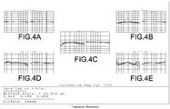
- FIGs. 4A through 4E are explanatory views showing transverse aberrations of the wide angle lens 100 shown in FIG. 1 .
- FIGs. 4A through 4E show transverse aberrations in the "X"-axis direction and the "Y"-axis direction at 0deg, 29.46deg, 55.40deg, 76.76deg and 95.90deg.
- "(R)” shows an aberration of a light of the wavelength 645nm
- "(G)” shows an aberration of a light of the wavelength 588nm
- "(B)” shows an aberration of a light of the wavelength 486nm.
- the aspherical coefficients A4, A6, A8 and A10 shown in FIG. 2 correspond to respective coefficients in the following aspherical surface function.
- Z is a sag amount
- c is an inverse number of a radius of curvature
- K is a conical coefficient
- r is a light height.
- a horizontal viewing angle of the wide-angle lens 100 shown in FIG. 1 is 120° or more.
- a first lens 11, a second lens 12, a third lens 13, a diaphragm 17, a fourth lens 14 and a fifth lens 15 are disposed in this order from an object side to an image side.
- a filter 18 and an imaging element 19 are disposed in this order on the image side with respect to the fifth lens 15.
- the first lens 11 is a negative meniscus lens with a convex surface facing the object side.
- a surface on the object side (first surface 1) of the first lens 11 which is a convex surface is a spherical surface
- a surface on the image side (second surface 2) which is a concave surface is an aspherical surface.
- the second lens 12 is a negative lens with a concave surface facing the image side.
- the second lens 12 is a negative meniscus lens with a concave surface facing the image side, and at least one of a lens surface on the object side (third surface 3) which is a convex surface and a lens surface on the image side (fourth surface 4) which is a concave surface is an aspherical surface.
- both of the lens surface on the object side (third surface 3) of the second lens 12 and the lens surface on the image side (fourth surface 4) are aspherical surfaces.
- the third lens 13 is a positive meniscus lens with a convex surface facing the image side or a biconvex lens, and at least one of a lens surface on the object side (fifth surface 5) and a lens surface on the image side (sixth surface 6) is an aspherical surface.
- the third lens 13 is a biconvex lens, and both of the lens surface on the object side (fifth surface 5) which is a convex surface and the lens surface on the image side (sixth surface 6) which is a convex surface are aspherical surfaces.
- the fourth lens 14 is a negative meniscus lens with a concave surface facing the image side or a biconcave lens.
- the fourth lens 14 is a negative meniscus lens with a concave surface facing the image side, and both of a surface on the object side (eighth surface 8) of the fourth lens 14 which is a convex surface and a surface on the image side (ninth surface 9) which is a concave surface are aspherical surfaces.
- the fifth lens 15 is a biconvex lens.
- the fourth lens 14 and the fifth lens 15 are plastic lenses and constitute a cemented lens 16 in which the lens surface on the image side of the fourth lens 14 and the lens surface on the object side of the fifth lens 15 are cemented each other.
- Both of a cemented surface (ninth surface 9) of the cemented lens 16 and a surface on the image side (tenth surface 10) of the fifth lens 15 which is a convex surface are aspherical surfaces.
- the first lens 11, the second lens 12 and the third lens 13 are also plastic lenses similarly to the fourth lens 14 and the fifth lens 15.
- Table 1 Main parameters of the wide angle lens 100 constituted as described above are shown in Table 1.
- the parameters shown in Table 1 are as follows. In Table 1, the parameters in a second through a fifth embodiments described below are also shown.
- the effective focal length "f0" Effective Focal Length
- the object-image distance Total Track / entire optical length
- the "F"-value of the entire lens system is 2.4
- the maximum viewing angle (Max. Field Angle) is 192deg
- the horizontal viewing angle (Horizontal Field Angle) is 192deg.
- the wide angle lens 100 satisfy all of the following conditional expressions (1), (2), (3), (4), (5) and (6).
- the refractive index "n4" of the fourth lens 14 is 1.632, which satisfies the following conditional expression (1). n 4 > 1.6
- the Abbe number "v4" of the fourth lens 14 is 23.3 and satisfies the following conditional expression (3). v 4 ⁇ 27
- the fourth lens 14 may be, for example, made of optical polyester resin (OKP4HT) made by Osaka Gas chemical KK.
- the composite focal length "f12" of the first lens 11 and the second lens 12 is -0.889mm, and the composite focal length "f345" of the third lens 13, the fourth lens 14 and the fifth lens 15 is 2.182mm. Therefore, the composite focal length "f12" and the composite focal length "f345" satisfy the following conditional expression (6).
- ⁇ 1 ⁇ f 12 / f 345 ⁇ 0.408 ⁇ 0
- the astigmatism / distortion (distortion aberration), the spherical aberration and the magnification chromatic aberration of the wide angle lens 100 constituted as described above are shown in FIGs. 3A through 3C , and the transverse aberrations are shown in FIGs. 4A through 4E . All the aberrations are small.
- the wide angle lens 100 in this embodiment is constituted of five lenses in four groups and each of the five lenses is made of a plastic lens. Therefore, even when a horizontal viewing angle of the wide angle lens 100 is 120° or more, the wide angle lens 100 can be made small-sized and lightweight at a low cost. Further, eight surfaces of totaled nine surfaces are aspherical surfaces and thus, as shown in FIGs. 3A through 3C , the aberrations can be reduced with a small number of lenses.
- the refractive index "n4" of the fourth lens 14 satisfies the conditional expression (1) and the refractive index "n4" is larger than 1.6. Therefore, the entire optical length of the wide angle lens 100 can be shortened and the radius of curvature "R45" of the cemented surface (ninth surface 9) of the cemented lens 16 and the effective focal length "f0" of the entire optical system can be easily constituted so as to satisfy the conditional expression (2). Accordingly, the magnification chromatic aberration can be reduced.
- a lower limit is set in the radius of curvature "R45" of the cemented surface (ninth surface 9) of the cemented lens 16 and thus the center radius of curvature of the lens surface on the image side of the fourth lens 14 which is a concave curved face is large and the center radius of curvature of the lens surface on the object side of the fifth lens 15 which is a convex curved face is large. Therefore, a manufacturing process and a cementing process of a lens single body can be stably performed and thus a load in the process is small.
- the Abbe number "v4" of the fourth lens 14 satisfies the conditional expression (3) and the Abbe number "v4" is smaller than 27. Therefore, the fourth lens 14 easily utilizes material whose refractive index "n4" is high and thus the magnification chromatic aberration and the like can be reduced.
- the composite focal length "f45" of the fourth lens 14 and the fifth lens 15 is short and satisfies the conditional expression (4). Therefore, the chromatic aberration and the like can be reduced. Further, the focal length "f4" of the fourth lens 14 is short and satisfies the conditional expression (5). Therefore, it is advantageous to reduce the chromatic aberration. Further, the composite focal length "f12" of the first lens 11 and the second lens 12 and the composite focal length "f345" of the third lens 13, the fourth lens 14 and the fifth lens 15 satisfy the conditional expression (6) and, in addition, the polarity of the composite focal length "f12" of the first lens 11 and the second lens 12 is minus. Therefore, it is advantageous in the temperature characteristic.
- FIG. 5 is an explanatory view showing a wide angle lens 100 in accordance with a second embodiment of the present invention.
- FIG. 6 is an explanatory view showing respective lens data, aspherical coefficients and the like of the wide angle lens 100 shown in FIG. 5 .
- FIGs. 7A, 7B and 7C are explanatory views showing aberrations of the wide angle lens 100 shown in FIG. 5 .
- FIGs. 8A through 8F are explanatory views showing transverse aberrations of the wide angle lens 100 shown in FIG. 5 .
- the basic constitution in this embodiment is similar to the first embodiment and thus the common portions are illustrated with the same reference signs and their detailed descriptions are omitted.
- a horizontal viewing angle of the wide-angle lens 100 shown in FIG. 5 is, similarly to the first embodiment, 120° or more and, in the wide angle lens 100, a first lens 11, a second lens 12, a third lens 13, a diaphragm 17, a fourth lens 14 and a fifth lens 15 are disposed in this order from an object side to an image side.
- the first lens 11 is a negative meniscus lens with a convex surface facing the object side.
- a surface on the object side (first surface 1) of the first lens 11 which is a convex surface is a spherical surface
- a surface on the image side (second surface 2) which is a concave surface is an aspherical surface.
- the second lens 12 is a negative lens with a concave surface facing the image side.
- the second lens 12 is a negative meniscus lens with a concave surface facing the image side, and at least one of a lens surface on the object side (third surface 3) which is a convex surface and a lens surface on the image side (fourth surface 4) which is a concave surface is an aspherical surface.
- both of the lens surface on the object side (third surface 3) of the second lens 12 and the lens surface on the image side (fourth surface 4) are aspherical surfaces.
- the third lens 13 is a positive meniscus lens with a convex surface facing the image side or a biconvex lens, and at least one of a lens surface on the object side (fifth surface 5) and a lens surface on the image side (sixth surface 6) is an aspherical surface.
- the third lens 13 is a positive meniscus lens with a convex surface facing the image side, and both of the lens surface on the object side (fifth surface 5) which is a concave surface and the lens surface on the image side (sixth surface 6) which is a convex surface are aspherical surfaces.
- the fourth lens 14 is a negative meniscus lens with a concave surface facing the image side or a biconcave lens.
- the fourth lens 14 is a negative meniscus lens with a concave surface facing the image side, and both of a surface on the object side (eighth surface 8) of the fourth lens 14 which is a convex surface and a surface on the image side (ninth surface 9) which is a concave surface are aspherical surfaces.
- the fifth lens 15 is a biconvex lens.
- the fourth lens 14 and the fifth lens 15 are plastic lenses and constitute a cemented lens 16 in which the lens surface on the image side of the fourth lens 14 and the lens surface on the object side of the fifth lens 15 are cemented each other.
- Both of a cemented surface (ninth surface 9) of the cemented lens 16 and a surface on the image side (tenth surface 10) of the fifth lens 15 which is a convex surface are aspherical surfaces.
- the first lens 11, the second lens 12 and the third lens 13 are also plastic lenses similarly to the fourth lens 14 and the fifth lens 15.
- the effective focal length "f0" of the entire optical system is 1.410mm
- the object-image distance is 11.378mm
- the "F"-value of the entire lens system is 2.0
- the maximum viewing angle is 156deg
- the horizontal viewing angle is 130deg.
- the wide angle lens 100 satisfies all of the above-mentioned conditional expressions (1), (2), (3), (4), (5) and (6).
- the refractive index "n4" of the fourth lens 14 is 1.632, which satisfies the conditional expression (1).
- a center radius of curvature "R45" of the cemented surface (ninth surface 9) of the cemented lens 16 is 0.750mm, and the effective focal length "f0" of the entire lens system is 1.410mm. Therefore,
- the Abbe number "v4" of the fourth lens 14 is 23.3 and satisfies the conditional expression (3).
- the composite focal length "f45" of the fourth lens 14 and the fifth lens 15 is 3.057mm, and the effective focal length "f0" of the entire lens system is 1.410mm. Therefore, “f45/f0” is 2.168 and the conditional expression (4) is satisfied.
- the astigmatism / distortion (distortion aberration), the spherical aberration and the magnification chromatic aberration of the wide angle lens 100 constituted as described above are shown in FIGs. 7A through 7C , and the transverse aberrations are shown in FIGs. 8A through 8F . All the aberrations are small.
- the wide angle lens 100 in this embodiment is constituted of five lenses in four groups and each of the five lenses is made of a plastic lens. Therefore, even when the horizontal viewing angle of the wide angle lens 100 is 120° or more, the wide angle lens 100 can be made small-sized and lightweight at a low cost. Further, eight surfaces of totaled nine surfaces are aspherical surfaces and thus, as shown in FIGs. 7A through 7C , the aberrations can be reduced with a small number of lenses.
- the radius of curvature "R45" of the cemented surface (ninth surface 9) of the cemented lens 16 and the effective focal length "f0" of the entire optical system satisfy the conditional expression (2) and thus the magnification chromatic aberration can be reduced.
- a lower limit is set in the radius of curvature "R45" of the cemented surface (ninth surface 9) of the cemented lens 16 and thus the center radius of curvature of the lens surface on the image side of the fourth lens 14 which is a concave curved face and the center radius of curvature of the lens surface on the object side of the fifth lens 15 which is a convex curved face are large. Therefore, a manufacturing process and a cementing process of a lens single body can be stably performed and similar effects to the first embodiment can be attained.
- FIG. 9 is an explanatory view showing a wide angle lens 100 in accordance with a third embodiment of the present invention.
- FIG. 10 is an explanatory view showing respective lens data, aspherical coefficients and the like of the wide angle lens 100 shown in FIG. 9 .
- FIGs. 11A, 11B and 11C are explanatory views showing aberrations of the wide angle lens 100 shown in FIG. 9 .
- FIGs. 12A through 12F are explanatory views showing transverse aberrations of the wide angle lens 100 shown in FIG. 9 .
- the basic constitution in this embodiment is similar to the first embodiment and thus the common portions are illustrated with the same reference signs and their detailed descriptions are omitted.
- a horizontal viewing angle of a wide-angle lens 100 shown in FIG. 9 is, similarly to the first embodiment, 120° or more and, in the wide angle lens 100, a first lens 11, a second lens 12, a third lens 13, a diaphragm 17, a fourth lens 14 and a fifth lens 15 are disposed in this order from an object side to an image side.
- the first lens 11 is a negative meniscus lens with a convex surface facing the object side.
- both of a surface on the object side (first surface 1) of the first lens 11 which is a convex surface and a surface on the image side (second surface 2) which is a concave surface are spherical surfaces.
- the second lens 12 is a negative lens with a concave surface facing the image side.
- the second lens 12 is a negative meniscus lens with a concave surface facing the image side, and at least one of a lens surface on the object side (third surface 3) which is a convex surface and a lens surface on the image side (fourth surface 4) which is a concave surface is an aspherical surface.
- both of the lens surface on the object side (third surface 3) of the second lens 12 and the lens surface on the image side (fourth surface 4) are aspherical surfaces.
- the third lens 13 is a positive meniscus lens with a convex surface facing the image side or a biconvex lens, and at least one of a lens surface on the object side (fifth surface 5) and a lens surface on the image side (sixth surface 6) is an aspherical surface.
- the third lens 13 is a positive meniscus lens with a convex surface facing the image side, and both of the lens surface on the object side (fifth surface 5) which is a concave surface and the lens surface on the image side (sixth surface 6) which is a convex surface are aspherical surfaces.
- the fourth lens 14 is a negative meniscus lens with a concave surface facing the image side or a biconcave lens.
- the fourth lens 14 is a negative meniscus lens with a concave surface facing the image side, and both of a surface on the object side (eighth surface 8) of the fourth lens 14 which is a convex surface and a surface on the image side (ninth surface 9) which is a concave surface are aspherical surfaces.
- the fifth lens 15 is a biconvex lens.
- the fourth lens 14 and the fifth lens 15 are plastic lenses and constitute a cemented lens 16 in which the lens surface on the image side of the fourth lens 14 and the lens surface on the object side of the fifth lens 15 are cemented each other.
- Both of a cemented surface (ninth surface 9) of the cemented lens 16 and a surface on the image side (tenth surface 10) of the fifth lens 15 which is a convex surface are aspherical surfaces.
- the first lens 11 is a glass lens and the second lens 12 and the third lens 13 are, similarly to the fourth lens 14 and the fifth lens 15, plastic lenses.
- the effective focal length "f0" of the entire optical system is 1.410mm
- the object-image distance is 11.465mm
- the "F"-value of the entire lens system is 2.0
- the maximum viewing angle is 156deg
- the horizontal viewing angle is 131 deg.
- the wide angle lens 100 satisfies all of the above-mentioned conditional expressions (1), (2), (3), (4), (5) and (6).
- the refractive index "n4" of the fourth lens 14 is 1.632, which satisfies the conditional expression (1).
- the center radius of curvature "R45" of the cemented surface (ninth surface 9) of the cemented lens 16 is 0.764mm, and the effective focal length "f0" of the entire lens system is 1.410mm. Therefore,”
- the Abbe number "v4" of the fourth lens 14 is 23.3 and satisfies the conditional expression (3).
- the composite focal length "f45" of the fourth lens 14 and the fifth lens 15 is 3.205mm, and the effective focal length "f0" of the entire lens system is 1.410mm. Therefore, “f45/f0” is 2.272 and the conditional expression (4) is satisfied.
- the astigmatism / distortion (distortion aberration), the spherical aberration and the magnification chromatic aberration of the wide angle lens 100 constituted as described above are shown in FIGs. 11A through 11C , and the transverse aberrations are shown in FIGs. 12A through 12F . All the aberrations are small.
- the wide angle lens 100 in this embodiment is constituted of five lenses in four groups and four lenses are made of plastic lenses. Therefore, even when the horizontal viewing angle of the wide angle lens 100 is 120° or more, the wide angle lens 100 can be made small-sized and lightweight at a low cost. Further, seven surfaces of totaled nine surfaces are aspherical surfaces and thus, as shown in FIGs. 11A through 11C , the aberrations can be reduced with a small number of lenses.
- the radius of curvature "R45" of the cemented surface (ninth surface 9) of the cemented lens 16 and the effective focal length "f0" of the entire optical system satisfy the conditional expression (2) and thus the magnification chromatic aberration can be reduced.
- a lower limit is set in the radius of curvature "R45" of the cemented surface (ninth surface 9) of the cemented lens 16 and thus the center radius of curvature of the lens surface on the image side of the fourth lens 14 which is a concave curved face and the center radius of curvature of the lens surface on the object side of the fifth lens 15 which is a convex curved face are large. Therefore, a manufacturing process and a cementing process of a lens single body can be stably performed and similar effects to the first embodiment can be attained.
- FIG. 13 is an explanatory view showing a wide angle lens 100 in accordance with a fourth embodiment of the present invention.
- FIG. 14 is an explanatory view showing respective lens data, aspherical coefficients and the like of the wide angle lens 100 shown in FIG. 13 .
- FIGs. 15A, 15B and 15C are explanatory views showing aberrations of the wide angle lens 100 shown in FIG. 13 .
- FIGs. 16A through 16E are explanatory views showing transverse aberrations of the wide angle lens 100 shown in FIG. 13 .
- the basic constitution in this embodiment is similar to the first embodiment and thus the common portions are illustrated with the same reference signs and their detailed descriptions are omitted.
- a horizontal viewing angle of a wide-angle lens 100 shown in FIG. 13 is, similarly to the first embodiment, 120° or more and, in the wide angle lens 100, a first lens 11, a second lens 12, a third lens 13, a diaphragm 17, a fourth lens 14 and a fifth lens 15 are disposed in this order from an object side to an image side.
- the first lens 11 is a negative meniscus lens with a convex surface facing the object side.
- both of a surface on the object side (first surface 1) of the first lens 11 which is a convex surface and a surface on the image side (second surface 2) which is a concave surface are spherical surfaces.
- the second lens 12 is a negative lens with a concave surface facing the image side.
- the second lens 12 is a negative meniscus lens with a concave surface facing the image side, and at least one of a lens surface on the object side (third surface 3) which is a convex surface and a lens surface on the image side (fourth surface 4) which is a concave surface is an aspherical surface.
- both of the lens surface on the object side (third surface 3) of the second lens 12 and the lens surface on the image side (fourth surface 4) are aspherical surfaces.
- the third lens 13 is a positive meniscus lens with a convex surface facing the image side or a biconvex lens, and at least one of a lens surface on the object side (fifth surface 5) and a lens surface on the image side (sixth surface 6) is an aspherical surface.
- the third lens 13 is a positive meniscus lens with a convex surface facing the image side, and both of the lens surface on the object side (fifth surface 5) which is a concave surface and the lens surface on the image side (sixth surface 6) which is a convex surface are aspherical surfaces.
- the fourth lens 14 is a negative meniscus lens with a concave surface facing the image side or a biconcave lens.
- the fourth lens 14 is a negative meniscus lens with a concave surface facing the image side, and both of a surface on the object side (eighth surface 8) of the fourth lens 14 which is a convex surface and a surface on the image side (ninth surface 9) which is a concave surface are aspherical surfaces.
- the fifth lens 15 is a biconvex lens.
- the fourth lens 14 and the fifth lens 15 are plastic lenses and constitute a cemented lens 16 in which the lens surface on the image side of the fourth lens 14 and the lens surface on the object side of the fifth lens 15 are cemented each other.
- Both of a cemented surface (ninth surface 9) of the cemented lens 16 and a surface on the image side (tenth surface 10) of the fifth lens 15 which is a convex surface are aspherical surfaces.
- the first lens 11 is a glass lens and the second lens 12 and the third lens 13 are, similarly to the fourth lens 14 and the fifth lens 15, plastic lenses.
- the effective focal length "f0" of the entire optical system is 1.056mm
- the object-image distance is 11.794mm
- the "F"-value of the entire lens system is 2.0
- the maximum viewing angle is 193deg
- the horizontal viewing angle is 193deg.
- the wide angle lens 100 satisfies all of the above-mentioned conditional expressions (1), (2), (3), (4), (5) and (6).
- the refractive index "n4" of the fourth lens 14 is 1.637, which satisfies the conditional expression (1).
- the center radius of curvature "R45" of the cemented surface (ninth surface 9) of the cemented lens 16 is 0.615mm and the effective focal length "f0" of the entire lens system is 1.056mm. Therefore,”
- the Abbe number "v4" of the fourth lens 14 is 24.0 and satisfies the conditional expression (3).
- the composite focal length "f45” of the fourth lens 14 and the fifth lens 15 is 3.055mm and the effective focal length "f0" of the entire lens system is 1.056mm. Therefore, “f45/f0” is 2.894 and the conditional expression (4) is satisfied.
- the astigmatism / distortion (distortion aberration), the spherical aberration and the magnification chromatic aberration of the wide angle lens 100 constituted as described above are shown in FIGs. 15A through 15C , and the transverse aberrations are shown in FIGs. 16A through 16E . All the aberrations are small.
- the wide angle lens 100 in this embodiment is constituted of five lenses in four groups and four lenses are made of plastic lenses. Therefore, even when the horizontal viewing angle of the wide angle lens 100 is 120° or more, the wide angle lens 100 can be made small-sized and lightweight at a low cost. Further, seven surfaces of totaled nine surfaces are aspherical surfaces and thus, as shown in FIGs. 15A through 15C , the aberrations can be reduced with a small number of lenses.
- the radius of curvature "R45" of the cemented surface (ninth surface 9) of the cemented lens 16 and the effective focal length "f0" of the entire optical system satisfy the conditional expression (2) and thus the magnification chromatic aberration can be reduced.
- a lower limit is set in the radius of curvature "R45” of the cemented surface (ninth surface 9) of the cemented lens 16 and thus the center radius of curvature of the lens surface on the image side of the fourth lens 14 which is a concave curved face and the center radius of curvature of the lens surface on the object side of the fifth lens 15 which is a convex curved face are large. Therefore, similar effects to the first embodiment can be attained, for example, a manufacturing process and a cementing process of a lens single body can be stably performed.
- FIG. 17 is an explanatory view showing a wide angle lens 100 in accordance with a fifth embodiment of the present invention.
- FIG. 18 is an explanatory view showing respective lens data, aspherical coefficients and the like of the wide angle lens 100 shown in FIG. 17 .
- FIGs. 19A, 19B and 19C are explanatory views showing aberrations of the wide angle lens 100 shown in FIG. 17 .
- FIGs. 20A through 20F are explanatory views showing transverse aberrations of the wide angle lens 100 shown in FIG. 17 .
- the basic constitution in this embodiment is similar to the first embodiment and thus the common portions are illustrated with the same reference signs and their detailed descriptions are omitted.
- a horizontal viewing angle of a wide-angle lens 100 shown in FIG. 17 is, similarly to the first embodiment, 120° or more and, in the wide angle lens 100, a first lens 11, a second lens 12, a third lens 13, a diaphragm 17, a fourth lens 14 and a fifth lens 15 are disposed in this order from an object side to an image side.
- the first lens 11 is a negative meniscus lens with a convex surface facing the object side.
- both of a surface on the object side (first surface 1) of the first lens 11 which is a convex surface and a surface on the image side (second surface 2) which is a concave surface are spherical surfaces.
- the second lens 12 is a negative lens with a concave surface facing the image side.
- the second lens 12 is a biconcave lens, and at least one of a lens surface on the object side (third surface 3) which is a concave surface and a lens surface on the image side (fourth surface 4) which is a concave surface is an aspherical surface.
- both of the lens surface on the object side (third surface 3) of the second lens 12 and the lens surface on the image side (fourth surface 4) are aspherical surfaces.
- the third lens 13 is a positive meniscus lens with a convex surface facing the image side or a biconvex lens, and at least one of a lens surface on the object side (fifth surface 5) and a lens surface on the image side (sixth surface 6) is an aspherical surface.
- the third lens 13 is a positive meniscus lens with a convex surface facing the image side, and both of the lens surface on the object side (fifth surface 5) which is a concave surface and the lens surface on the image side (sixth surface 6) which is a convex surface are aspherical surfaces.
- the fourth lens 14 is a negative meniscus lens with a concave surface facing the image side or a biconcave lens.
- the fourth lens 14 is a negative meniscus lens with a concave surface facing the image side, and both of a surface on the object side (eighth surface 8) of the fourth lens 14 which is a convex surface and a surface on the image side (ninth surface 9) which is a concave surface are aspherical surfaces.
- the fifth lens 15 is a biconvex lens.
- the fourth lens 14 and the fifth lens 15 are plastic lenses and constitute a cemented lens 16 in which the lens surface on the image side of the fourth lens 14 and the lens surface on the object side of the fifth lens 15 are cemented each other.
- Both of a cemented surface (ninth surface 9) of the cemented lens 16 and a surface on the image side (tenth surface 10) of the fifth lens 15 which is a convex surface are aspherical surfaces.
- the first lens 11 is a glass lens and the second lens 12 and the third lens 13 are, similarly to the fourth lens 14 and the fifth lens 15, plastic lenses.
- the wide angle lens 100 constituted as described above, the effective focal length "f0" of the entire optical system is 0.669mm, the object-image distance is 11.702mm, the "F"-value of the entire lens system is 2.0, the maximum viewing angle is 196deg, and the horizontal viewing angle is 161deg.
- the wide angle lens 100 satisfies all of the above-mentioned conditional expressions (1), (2), (3), (4), (5) and (6).
- the refractive index "n4" of the fourth lens 14 is 1.637, which satisfies the conditional expression (1).
- the center radius of curvature "R45" of the cemented surface (ninth surface 9) of the cemented lens 16 is 0.472mm and the effective focal length "f0" of the entire lens system is 0.669mm. Therefore, "
- the Abbe number "v4" of the fourth lens 14 is 24.0 and satisfies the conditional expression (3).
- the composite focal length "f45” of the fourth lens 14 and the fifth lens 15 is 1.884mm and the effective focal length "f0" of the entire lens system is 0.669mm. Therefore, “f45/f0” is 2.815 and the conditional expression (4) is satisfied.
- the astigmatism / distortion (distortion aberration), the spherical aberration and the magnification chromatic aberration of the wide angle lens 100 constituted as described above are shown in FIGs. 19A through 19C , and the transverse aberrations are shown in FIGs. 20A through 20F . All the aberrations are small.
- the wide angle lens 100 in this embodiment is constituted of five lenses in four groups and four lenses are made of plastic lenses. Therefore, even when a horizontal viewing angle of the wide angle lens 100 is 120° or more, the wide angle lens 100 can be made small-sized and lightweight at a low cost. Further, seven surfaces of totaled nine surfaces are aspherical surfaces and thus, as shown in FIGs. 19A through 19C , the aberrations can be reduced with a small number of lenses.
- the radius of curvature "R45" of the cemented surface (ninth surface 9) of the cemented lens 16 and the effective focal length "f0" of the entire optical system satisfy the conditional expression (2) and thus the magnification chromatic aberration can be reduced.
- a lower limit is set in the radius of curvature "R45” of the cemented surface (ninth surface 9) of the cemented lens 16 and thus the center radius of curvature of the lens surface on the image side of the fourth lens 14 which is a concave curved face and the center radius of curvature of the lens surface on the object side of the fifth lens 15 which is a convex curved face are large. Therefore, similar effects to the first embodiment can be attained, for example, a manufacturing process and a cementing process of a lens single body can be stably performed.
Abstract
Description
- The present invention relates to a wide angle lens constituted of five lenses in four groups.
- A wide angle lens as an image pickup lens has been proposed which is constituted of five lenses in four groups which includes, from an object side toward an image side, a first lens, a second lens, a third lens, a diaphragm, a fourth lens and a fifth lens in this order, and the fourth lens and the fifth lens constitute a cemented lens (see Japanese Patent Laid-Open No.
2015-45803 - In the wide angle lens described in the Patent Literature, an effective focal length of the entire lens system is 1mm, and the center radius of curvature of the cemented surface (ninth face) of the cemented lens is 0.4327mm. Therefore, a curvature of the lens surface on the image side of the fourth lens which is a concave curved face and a curvature of the lens surface on the object side of the fifth lens which is a convex curved face are large and thus it is difficult to stably perform a manufacturing process and a cementing process of a lens single body and a load in the processes is large.
- In view of the problem described above, an objective of the present invention is to provide a wide angle lens which is capable of reducing an aberration without increasing a load in the process.
- To achieve the above mentioned objective, the present invention provides a wide angle lens comprising a first lens, a second lens, a third lens, a diaphragm, a fourth lens and a fifth lens which are arranged in order from an object side to an image side. The first lens is a negative meniscus lens with a convex surface facing the object side, the second lens is a negative lens with a concave surface facing the image side and at least one of a lens surface on the object side and a lens surface on the image side is an aspherical surface, and the third lens is a positive meniscus lens with a convex surface facing the image side or a biconvex lens and at least one of a lens surface on the object side and a lens surface on the image side is an aspherical surface. The fourth lens is a negative meniscus lens with a concave surface facing the image side or a biconcave lens, the fifth lens is a biconvex lens, and the fourth lens and the fifth lens are plastic lenses which constitute a cemented lens in which a lens surface on the image side of the fourth lens and a lens surface on the object side of the fifth lens are cemented. In addition, when a refractive index of the fourth lens is "n4", the following condition (1) is satisfied:


- In the wide angle lens in accordance with the present invention, the refractive index "n4" of the fourth lens satisfies the condition (1) and thus the entire optical length can be shortened and the wide angle lens can be constituted so that the radius of curvature "R45" of the cemented surface of the cemented lens and the effective focal length "f0" of the entire optical system satisfy the condition (2). Therefore, the magnification chromatic aberration can be reduced. Further, a lower limit is set in the radius of curvature "R45" of the cemented surface of the cemented lens and thus the center radius of curvature of a lens surface on the image side of the fourth lens which is a concave curved face and the center radius of curvature of a lens surface on the object side of the fifth lens which is a convex curved face are large. Therefore, a manufacturing process and a cementing process of a lens single body can be stably performed and thus a load in the process is small.
- In the present invention, it may be adopted that, when the Abbe number of the fourth lens is "v4", the following condition (3) is satisfied:

- In the present invention, it may be adopted that, when a composite focal length of the fourth lens and the fifth lens is "f45", the following condition (4) is satisfied:

- In the present invention, it may be adopted that, when a focal length of the fourth lens is "f4", the following condition (5) is satisfied:

- In the present invention, it may be adopted that, when a composite focal length of the first lens and the second lens is "f12" and a composite focal length of the third lens, the fourth lens and the fifth lens is "f345", the following condition (6) is satisfied:

- In the present invention, it may be adopted that a horizontal viewing angle of the wide angle lens is 120 degrees or more.
- Other features and advantages of the invention will be apparent from the following detailed description, taken in conjunction with the accompanying drawings that illustrate, by way of example, various features of embodiments of the invention.
- Embodiments will now be described, by way of example only, with reference to the accompanying drawings which are meant to be exemplary, not limiting, and wherein like elements are numbered alike in several Figures, in which:
-
FIG. 1 is an explanatory view showing a wide angle lens in accordance with a first embodiment of the present invention. -
FIG. 2 is an explanatory view showing respective lens data, aspherical coefficients and the like of a wide angle lens shown inFIG. 1 . -
FIGs. 3A, 3B and 3C are explanatory views showing astigmatism and the like of a wide angle lens shown inFIG. 1 . -
FIGs. 4A through 4E are explanatory views showing transverse aberrations of a wide angle lens shown inFIG. 1 . -
FIG. 5 is an explanatory view showing a wide angle lens in accordance with a second embodiment of the present invention. -
FIG. 6 is an explanatory view showing respective lens data, aspherical coefficients and the like of a wide angle lens shown inFIG. 5 . -
FIGs. 7A, 7B and 7C are explanatory views showing astigmatism and the like of a wide angle lens shown inFIG. 5 . -
FIGs. 8A through 8F are explanatory views showing transverse aberrations of a wide angle lens shown inFIG. 5 . -
FIG. 9 is an explanatory view showing a wide angle lens in accordance with a third embodiment of the present invention. -
FIG. 10 is an explanatory view showing respective lens data, aspherical coefficients and the like of a wide angle lens shown inFIG. 9 . -
FIGs. 11A, 11B and 11C are explanatory views showing astigmatism and the like of a wide angle lens shown inFIG. 9 . -
FIGs. 12A through 12F are explanatory views showing transverse aberrations of a wide angle lens shown inFIG. 9 . -
FIG. 13 is an explanatory view showing a wide angle lens in accordance with a fourth embodiment of the present invention. -
FIG. 14 is an explanatory view showing respective lens data, aspherical coefficients and the like of a wide angle lens shown inFIG. 13 . -
FIGs. 15A, 15B and 15C are explanatory views showing astigmatism and the like of a wide angle lens shown inFIG. 13 . -
FIGs. 16A through 16E are explanatory views showing transverse aberrations of a wide angle lens shown inFIG. 13 . -
FIG. 17 is an explanatory view showing a wide angle lens in accordance with a fifth embodiment of the present invention. -
FIG. 18 is an explanatory view showing respective lens data, aspherical coefficients and the like of a wide angle lens shown inFIG. 17 . -
FIGs. 19A, 19B and 19C are explanatory views showing astigmatism and the like of a wide angle lens shown inFIG. 17 . -
FIGs. 20A through 20F are explanatory views showing transverse aberrations of a wide angle lens shown inFIG. 17 . - Wide-angle lenses to which the present invention is applied will be described below with reference to the accompanying drawings. In the following description, the unit is "mm" unless there is a specific indication.
-
FIG. 1 is an explanatory view showing awide angle lens 100 in accordance with a first embodiment of the present invention. InFIG. 1 , surface numbers corresponding to lens data and aspherical coefficients are indicated by using a parenthesis. Further, the surface added with the mark "*" after the surface number is an aspherical surface.FIG. 2 is an explanatory view showing respective lens data, aspherical coefficients and the like of thewide angle lens 100 shown inFIG. 1 .FIGs. 3A, 3B and 3C are explanatory views showing astigmatism and the like of thewide angle lens 100 shown inFIG. 1 .FIG. 3A is an explanatory view showing astigmatism / distortion (distortion aberration),FIG. 3B is an explanatory view showing a spherical aberration andFIG. 3C is an explanatory view showing a magnification chromatic aberration. InFIG. 3A , "S" shows characteristic in a sagittal direction and "T" shows characteristic in a tangential direction. The distortion indicates a variation ratio of an image between an imaging center part and a peripheral part and, the smaller the absolute value of a numerical value indicating the distortion is, the higher the precision of the lens is.FIGs. 4A through 4E are explanatory views showing transverse aberrations of thewide angle lens 100 shown inFIG. 1 .FIGs. 4A through 4E show transverse aberrations in the "X"-axis direction and the "Y"-axis direction at 0deg, 29.46deg, 55.40deg, 76.76deg and 95.90deg. InFIGs. 3A through 3C , "(R)" shows an aberration of a light of the wavelength 645nm, "(G)" shows an aberration of a light of the wavelength 588nm, and "(B)" shows an aberration of a light of the wavelength 486nm. The aspherical coefficients A4, A6, A8 and A10 shown inFIG. 2 correspond to respective coefficients in the following aspherical surface function. In this expression, "Z" is a sag amount, "c" is an inverse number of a radius of curvature, "K" is a conical coefficient, and "r" is a light height.
- A horizontal viewing angle of the wide-
angle lens 100 shown inFIG. 1 is 120° or more. In thewide angle lens 100, afirst lens 11, asecond lens 12, athird lens 13, adiaphragm 17, afourth lens 14 and afifth lens 15 are disposed in this order from an object side to an image side. Afilter 18 and animaging element 19 are disposed in this order on the image side with respect to thefifth lens 15. Thefirst lens 11 is a negative meniscus lens with a convex surface facing the object side. In this embodiment, a surface on the object side (first surface 1) of thefirst lens 11 which is a convex surface is a spherical surface, and a surface on the image side (second surface 2) which is a concave surface is an aspherical surface. - The
second lens 12 is a negative lens with a concave surface facing the image side. In this embodiment, thesecond lens 12 is a negative meniscus lens with a concave surface facing the image side, and at least one of a lens surface on the object side (third surface 3) which is a convex surface and a lens surface on the image side (fourth surface 4) which is a concave surface is an aspherical surface. In this embodiment, both of the lens surface on the object side (third surface 3) of thesecond lens 12 and the lens surface on the image side (fourth surface 4) are aspherical surfaces. - The
third lens 13 is a positive meniscus lens with a convex surface facing the image side or a biconvex lens, and at least one of a lens surface on the object side (fifth surface 5) and a lens surface on the image side (sixth surface 6) is an aspherical surface. In this embodiment, thethird lens 13 is a biconvex lens, and both of the lens surface on the object side (fifth surface 5) which is a convex surface and the lens surface on the image side (sixth surface 6) which is a convex surface are aspherical surfaces. - The
fourth lens 14 is a negative meniscus lens with a concave surface facing the image side or a biconcave lens. In this embodiment, thefourth lens 14 is a negative meniscus lens with a concave surface facing the image side, and both of a surface on the object side (eighth surface 8) of thefourth lens 14 which is a convex surface and a surface on the image side (ninth surface 9) which is a concave surface are aspherical surfaces. - The
fifth lens 15 is a biconvex lens. Thefourth lens 14 and thefifth lens 15 are plastic lenses and constitute a cementedlens 16 in which the lens surface on the image side of thefourth lens 14 and the lens surface on the object side of thefifth lens 15 are cemented each other. Both of a cemented surface (ninth surface 9) of the cementedlens 16 and a surface on the image side (tenth surface 10) of thefifth lens 15 which is a convex surface are aspherical surfaces. In this embodiment, thefirst lens 11, thesecond lens 12 and thethird lens 13 are also plastic lenses similarly to thefourth lens 14 and thefifth lens 15. - Main parameters of the
wide angle lens 100 constituted as described above are shown in Table 1. The parameters shown in Table 1 are as follows. In Table 1, the parameters in a second through a fifth embodiments described below are also shown. - f0
- effective focal length of the entire lens system
- f4
- focal length of the
fourth lens 14 - f12
- composite focal length of the
first lens 11 and thesecond lens 12 - f345
- composite focal length of the
third lens 13, thefourth lens 14 and thefifth lens 15 - f45
- composite focal length of the
fourth lens 14 and thefifth lens 15 - R45
- center radius of curvature of a cemented surface of the cemented
lens 16 - n4
- refractive index of the
fourth lens 14 - v4
- Abbe number of the
fourth lens 14 - As shown in
FIG. 2 , in thewide angle lens 100, the effective focal length "f0" (Effective Focal Length) of the entire optical system is 0.822mm, the object-image distance (Total Track / entire optical length) is 9.206mm, the "F"-value of the entire lens system (Image Space F/#) is 2.4, the maximum viewing angle (Max. Field Angle) is 192deg, and the horizontal viewing angle (Horizontal Field Angle) is 192deg. - Further, as shown in
FIG. 2 and Table 1, thewide angle lens 100 satisfy all of the following conditional expressions (1), (2), (3), (4), (5) and (6). First, the refractive index "n4" of thefourth lens 14 is 1.632, which satisfies the following conditional expression (1).
- A center radius of curvature "R45" of the cemented surface (ninth surface 9) of the cemented
lens 16 is 0.515mm, and the effective focal length "f0" of the entire lens system is 0.822mm. Therefore, the following conditional expression (2) is satisfied.
- The Abbe number "v4" of the
fourth lens 14 is 23.3 and satisfies the following conditional expression (3).
- The
fourth lens 14 may be, for example, made of optical polyester resin (OKP4HT) made by Osaka Gas chemical KK. - The composite focal length "f45" of the
fourth lens 14 and thefifth lens 15 is 2.314mm, and the effective focal length "f0" of the entire lens system is 0.822mm. Therefore, the following conditional expression (4) is satisfied.
- The focal length "f4" of the
fourth lens 14 is -1.454mm, and the effective focal length "f0" of the entire lens system is 0.822mm. Therefore, the focal length "f4" satisfies the following conditional expression (5).
- The composite focal length "f12" of the
first lens 11 and thesecond lens 12 is -0.889mm, and the composite focal length "f345" of thethird lens 13, thefourth lens 14 and thefifth lens 15 is 2.182mm. Therefore, the composite focal length "f12" and the composite focal length "f345" satisfy the following conditional expression (6).
- The astigmatism / distortion (distortion aberration), the spherical aberration and the magnification chromatic aberration of the
wide angle lens 100 constituted as described above are shown inFIGs. 3A through 3C , and the transverse aberrations are shown inFIGs. 4A through 4E . All the aberrations are small. - As described above, the
wide angle lens 100 in this embodiment is constituted of five lenses in four groups and each of the five lenses is made of a plastic lens. Therefore, even when a horizontal viewing angle of thewide angle lens 100 is 120° or more, thewide angle lens 100 can be made small-sized and lightweight at a low cost. Further, eight surfaces of totaled nine surfaces are aspherical surfaces and thus, as shown inFIGs. 3A through 3C , the aberrations can be reduced with a small number of lenses. - In the
wide angle lens 100 in this embodiment, the refractive index "n4" of thefourth lens 14 satisfies the conditional expression (1) and the refractive index "n4" is larger than 1.6. Therefore, the entire optical length of thewide angle lens 100 can be shortened and the radius of curvature "R45" of the cemented surface (ninth surface 9) of the cementedlens 16 and the effective focal length "f0" of the entire optical system can be easily constituted so as to satisfy the conditional expression (2). Accordingly, the magnification chromatic aberration can be reduced. Further, a lower limit is set in the radius of curvature "R45" of the cemented surface (ninth surface 9) of the cementedlens 16 and thus the center radius of curvature of the lens surface on the image side of thefourth lens 14 which is a concave curved face is large and the center radius of curvature of the lens surface on the object side of thefifth lens 15 which is a convex curved face is large. Therefore, a manufacturing process and a cementing process of a lens single body can be stably performed and thus a load in the process is small. In addition, the Abbe number "v4" of thefourth lens 14 satisfies the conditional expression (3) and the Abbe number "v4" is smaller than 27. Therefore, thefourth lens 14 easily utilizes material whose refractive index "n4" is high and thus the magnification chromatic aberration and the like can be reduced. - The composite focal length "f45" of the
fourth lens 14 and thefifth lens 15 is short and satisfies the conditional expression (4). Therefore, the chromatic aberration and the like can be reduced. Further, the focal length "f4" of thefourth lens 14 is short and satisfies the conditional expression (5). Therefore, it is advantageous to reduce the chromatic aberration. Further, the composite focal length "f12" of thefirst lens 11 and thesecond lens 12 and the composite focal length "f345" of thethird lens 13, thefourth lens 14 and thefifth lens 15 satisfy the conditional expression (6) and, in addition, the polarity of the composite focal length "f12" of thefirst lens 11 and thesecond lens 12 is minus. Therefore, it is advantageous in the temperature characteristic. -
FIG. 5 is an explanatory view showing awide angle lens 100 in accordance with a second embodiment of the present invention.FIG. 6 is an explanatory view showing respective lens data, aspherical coefficients and the like of thewide angle lens 100 shown inFIG. 5 .FIGs. 7A, 7B and 7C are explanatory views showing aberrations of thewide angle lens 100 shown inFIG. 5 .FIGs. 8A through 8F are explanatory views showing transverse aberrations of thewide angle lens 100 shown inFIG. 5 . The basic constitution in this embodiment is similar to the first embodiment and thus the common portions are illustrated with the same reference signs and their detailed descriptions are omitted. - A horizontal viewing angle of the wide-
angle lens 100 shown inFIG. 5 is, similarly to the first embodiment, 120° or more and, in thewide angle lens 100, afirst lens 11, asecond lens 12, athird lens 13, adiaphragm 17, afourth lens 14 and afifth lens 15 are disposed in this order from an object side to an image side. Thefirst lens 11 is a negative meniscus lens with a convex surface facing the object side. In this embodiment, a surface on the object side (first surface 1) of thefirst lens 11 which is a convex surface is a spherical surface, and a surface on the image side (second surface 2) which is a concave surface is an aspherical surface. - The
second lens 12 is a negative lens with a concave surface facing the image side. In this embodiment, thesecond lens 12 is a negative meniscus lens with a concave surface facing the image side, and at least one of a lens surface on the object side (third surface 3) which is a convex surface and a lens surface on the image side (fourth surface 4) which is a concave surface is an aspherical surface. In this embodiment, both of the lens surface on the object side (third surface 3) of thesecond lens 12 and the lens surface on the image side (fourth surface 4) are aspherical surfaces. - The
third lens 13 is a positive meniscus lens with a convex surface facing the image side or a biconvex lens, and at least one of a lens surface on the object side (fifth surface 5) and a lens surface on the image side (sixth surface 6) is an aspherical surface. In this embodiment, thethird lens 13 is a positive meniscus lens with a convex surface facing the image side, and both of the lens surface on the object side (fifth surface 5) which is a concave surface and the lens surface on the image side (sixth surface 6) which is a convex surface are aspherical surfaces. - The
fourth lens 14 is a negative meniscus lens with a concave surface facing the image side or a biconcave lens. In this embodiment, thefourth lens 14 is a negative meniscus lens with a concave surface facing the image side, and both of a surface on the object side (eighth surface 8) of thefourth lens 14 which is a convex surface and a surface on the image side (ninth surface 9) which is a concave surface are aspherical surfaces. - The
fifth lens 15 is a biconvex lens. Thefourth lens 14 and thefifth lens 15 are plastic lenses and constitute a cementedlens 16 in which the lens surface on the image side of thefourth lens 14 and the lens surface on the object side of thefifth lens 15 are cemented each other. Both of a cemented surface (ninth surface 9) of the cementedlens 16 and a surface on the image side (tenth surface 10) of thefifth lens 15 which is a convex surface are aspherical surfaces. In this embodiment, thefirst lens 11, thesecond lens 12 and thethird lens 13 are also plastic lenses similarly to thefourth lens 14 and thefifth lens 15. - In the
wide angle lens 100 constituted as described above, the effective focal length "f0" of the entire optical system is 1.410mm, the object-image distance is 11.378mm, the "F"-value of the entire lens system is 2.0, the maximum viewing angle is 156deg, and the horizontal viewing angle is 130deg. - Further, as shown in
FIG. 6 and Table 1, thewide angle lens 100 satisfies all of the above-mentioned conditional expressions (1), (2), (3), (4), (5) and (6). First, the refractive index "n4" of thefourth lens 14 is 1.632, which satisfies the conditional expression (1). A center radius of curvature "R45" of the cemented surface (ninth surface 9) of the cementedlens 16 is 0.750mm, and the effective focal length "f0" of the entire lens system is 1.410mm. Therefore, | R45/f0 | is 0.532 and thus the conditional expression (2) is satisfied. The Abbe number "v4" of thefourth lens 14 is 23.3 and satisfies the conditional expression (3). - The composite focal length "f45" of the
fourth lens 14 and thefifth lens 15 is 3.057mm, and the effective focal length "f0" of the entire lens system is 1.410mm. Therefore, "f45/f0" is 2.168 and the conditional expression (4) is satisfied. The focal length "f4" of thefourth lens 14 is -2.787mm and the effective focal length "f0" of the entire lens system is 1.410mm. Therefore, "f4/f0" = -1.976 and thus the conditional expression (5) is satisfied. The composite focal length "f12" of thefirst lens 11 and thesecond lens 12 is -1.662mm, and the composite focal length "f345" of thethird lens 13, thefourth lens 14 and thefifth lens 15 is 2.648mm. Therefore, "f12/f345" = -0.628, and thus the conditional expression (6) is satisfied. - The astigmatism / distortion (distortion aberration), the spherical aberration and the magnification chromatic aberration of the
wide angle lens 100 constituted as described above are shown inFIGs. 7A through 7C , and the transverse aberrations are shown inFIGs. 8A through 8F . All the aberrations are small. - As described above, the
wide angle lens 100 in this embodiment is constituted of five lenses in four groups and each of the five lenses is made of a plastic lens. Therefore, even when the horizontal viewing angle of thewide angle lens 100 is 120° or more, thewide angle lens 100 can be made small-sized and lightweight at a low cost. Further, eight surfaces of totaled nine surfaces are aspherical surfaces and thus, as shown inFIGs. 7A through 7C , the aberrations can be reduced with a small number of lenses. - Further, in the
wide angle lens 100 in this embodiment, the radius of curvature "R45" of the cemented surface (ninth surface 9) of the cementedlens 16 and the effective focal length "f0" of the entire optical system satisfy the conditional expression (2) and thus the magnification chromatic aberration can be reduced. Further, a lower limit is set in the radius of curvature "R45" of the cemented surface (ninth surface 9) of the cementedlens 16 and thus the center radius of curvature of the lens surface on the image side of thefourth lens 14 which is a concave curved face and the center radius of curvature of the lens surface on the object side of thefifth lens 15 which is a convex curved face are large. Therefore, a manufacturing process and a cementing process of a lens single body can be stably performed and similar effects to the first embodiment can be attained. -
FIG. 9 is an explanatory view showing awide angle lens 100 in accordance with a third embodiment of the present invention.FIG. 10 is an explanatory view showing respective lens data, aspherical coefficients and the like of thewide angle lens 100 shown inFIG. 9 .FIGs. 11A, 11B and 11C are explanatory views showing aberrations of thewide angle lens 100 shown inFIG. 9 .FIGs. 12A through 12F are explanatory views showing transverse aberrations of thewide angle lens 100 shown inFIG. 9 . The basic constitution in this embodiment is similar to the first embodiment and thus the common portions are illustrated with the same reference signs and their detailed descriptions are omitted. - A horizontal viewing angle of a wide-
angle lens 100 shown inFIG. 9 is, similarly to the first embodiment, 120° or more and, in thewide angle lens 100, afirst lens 11, asecond lens 12, athird lens 13, adiaphragm 17, afourth lens 14 and afifth lens 15 are disposed in this order from an object side to an image side. Thefirst lens 11 is a negative meniscus lens with a convex surface facing the object side. In this embodiment, both of a surface on the object side (first surface 1) of thefirst lens 11 which is a convex surface and a surface on the image side (second surface 2) which is a concave surface are spherical surfaces. - The
second lens 12 is a negative lens with a concave surface facing the image side. In this embodiment, thesecond lens 12 is a negative meniscus lens with a concave surface facing the image side, and at least one of a lens surface on the object side (third surface 3) which is a convex surface and a lens surface on the image side (fourth surface 4) which is a concave surface is an aspherical surface. In this embodiment, both of the lens surface on the object side (third surface 3) of thesecond lens 12 and the lens surface on the image side (fourth surface 4) are aspherical surfaces. - The
third lens 13 is a positive meniscus lens with a convex surface facing the image side or a biconvex lens, and at least one of a lens surface on the object side (fifth surface 5) and a lens surface on the image side (sixth surface 6) is an aspherical surface. In this embodiment, thethird lens 13 is a positive meniscus lens with a convex surface facing the image side, and both of the lens surface on the object side (fifth surface 5) which is a concave surface and the lens surface on the image side (sixth surface 6) which is a convex surface are aspherical surfaces. - The
fourth lens 14 is a negative meniscus lens with a concave surface facing the image side or a biconcave lens. In this embodiment, thefourth lens 14 is a negative meniscus lens with a concave surface facing the image side, and both of a surface on the object side (eighth surface 8) of thefourth lens 14 which is a convex surface and a surface on the image side (ninth surface 9) which is a concave surface are aspherical surfaces. - The
fifth lens 15 is a biconvex lens. Thefourth lens 14 and thefifth lens 15 are plastic lenses and constitute a cementedlens 16 in which the lens surface on the image side of thefourth lens 14 and the lens surface on the object side of thefifth lens 15 are cemented each other. Both of a cemented surface (ninth surface 9) of the cementedlens 16 and a surface on the image side (tenth surface 10) of thefifth lens 15 which is a convex surface are aspherical surfaces. In this embodiment, thefirst lens 11 is a glass lens and thesecond lens 12 and thethird lens 13 are, similarly to thefourth lens 14 and thefifth lens 15, plastic lenses. - In the
wide angle lens 100 constituted as described above, the effective focal length "f0" of the entire optical system is 1.410mm, the object-image distance is 11.465mm, the "F"-value of the entire lens system is 2.0, the maximum viewing angle is 156deg, and the horizontal viewing angle is 131 deg. - Further, as shown in
FIG. 10 and Table 1, thewide angle lens 100 satisfies all of the above-mentioned conditional expressions (1), (2), (3), (4), (5) and (6). First, the refractive index "n4" of thefourth lens 14 is 1.632, which satisfies the conditional expression (1). Further, the center radius of curvature "R45" of the cemented surface (ninth surface 9) of the cementedlens 16 is 0.764mm, and the effective focal length "f0" of the entire lens system is 1.410mm. Therefore,"| R45/f0 |" is 0.542 and thus the conditional expression (2) is satisfied. The Abbe number "v4" of thefourth lens 14 is 23.3 and satisfies the conditional expression (3). - The composite focal length "f45" of the
fourth lens 14 and thefifth lens 15 is 3.205mm, and the effective focal length "f0" of the entire lens system is 1.410mm. Therefore, "f45/f0" is 2.272 and the conditional expression (4) is satisfied. The focal length "f4" of thefourth lens 14 is -2.249mm and the effective focal length "f0" of the entire lens system is 1.410mm. Therefore, "f4/f0" = -1.595 and thus the conditional expression (5) is satisfied. The composite focal length "f12" of thefirst lens 11 and thesecond lens 12 is -1.807mm and the composite focal length "f345" of thethird lens 13, thefourth lens 14 and thefifth lens 15 is 2.671mm. Therefore, "f12/f345" = -0.676 and thus the conditional expression (6) is satisfied. - The astigmatism / distortion (distortion aberration), the spherical aberration and the magnification chromatic aberration of the
wide angle lens 100 constituted as described above are shown inFIGs. 11A through 11C , and the transverse aberrations are shown inFIGs. 12A through 12F . All the aberrations are small. - As described above, the
wide angle lens 100 in this embodiment is constituted of five lenses in four groups and four lenses are made of plastic lenses. Therefore, even when the horizontal viewing angle of thewide angle lens 100 is 120° or more, thewide angle lens 100 can be made small-sized and lightweight at a low cost. Further, seven surfaces of totaled nine surfaces are aspherical surfaces and thus, as shown inFIGs. 11A through 11C , the aberrations can be reduced with a small number of lenses. - Further, in the
wide angle lens 100 in this embodiment, the radius of curvature "R45" of the cemented surface (ninth surface 9) of the cementedlens 16 and the effective focal length "f0" of the entire optical system satisfy the conditional expression (2) and thus the magnification chromatic aberration can be reduced. Further, a lower limit is set in the radius of curvature "R45" of the cemented surface (ninth surface 9) of the cementedlens 16 and thus the center radius of curvature of the lens surface on the image side of thefourth lens 14 which is a concave curved face and the center radius of curvature of the lens surface on the object side of thefifth lens 15 which is a convex curved face are large. Therefore, a manufacturing process and a cementing process of a lens single body can be stably performed and similar effects to the first embodiment can be attained. -
FIG. 13 is an explanatory view showing awide angle lens 100 in accordance with a fourth embodiment of the present invention.FIG. 14 is an explanatory view showing respective lens data, aspherical coefficients and the like of thewide angle lens 100 shown inFIG. 13 .FIGs. 15A, 15B and 15C are explanatory views showing aberrations of thewide angle lens 100 shown inFIG. 13 .FIGs. 16A through 16E are explanatory views showing transverse aberrations of thewide angle lens 100 shown inFIG. 13 . The basic constitution in this embodiment is similar to the first embodiment and thus the common portions are illustrated with the same reference signs and their detailed descriptions are omitted. - A horizontal viewing angle of a wide-
angle lens 100 shown inFIG. 13 is, similarly to the first embodiment, 120° or more and, in thewide angle lens 100, afirst lens 11, asecond lens 12, athird lens 13, adiaphragm 17, afourth lens 14 and afifth lens 15 are disposed in this order from an object side to an image side. Thefirst lens 11 is a negative meniscus lens with a convex surface facing the object side. In this embodiment, both of a surface on the object side (first surface 1) of thefirst lens 11 which is a convex surface and a surface on the image side (second surface 2) which is a concave surface are spherical surfaces. - The
second lens 12 is a negative lens with a concave surface facing the image side. In this embodiment, thesecond lens 12 is a negative meniscus lens with a concave surface facing the image side, and at least one of a lens surface on the object side (third surface 3) which is a convex surface and a lens surface on the image side (fourth surface 4) which is a concave surface is an aspherical surface. In this embodiment, both of the lens surface on the object side (third surface 3) of thesecond lens 12 and the lens surface on the image side (fourth surface 4) are aspherical surfaces. - The
third lens 13 is a positive meniscus lens with a convex surface facing the image side or a biconvex lens, and at least one of a lens surface on the object side (fifth surface 5) and a lens surface on the image side (sixth surface 6) is an aspherical surface. In this embodiment, thethird lens 13 is a positive meniscus lens with a convex surface facing the image side, and both of the lens surface on the object side (fifth surface 5) which is a concave surface and the lens surface on the image side (sixth surface 6) which is a convex surface are aspherical surfaces. - The
fourth lens 14 is a negative meniscus lens with a concave surface facing the image side or a biconcave lens. In this embodiment, thefourth lens 14 is a negative meniscus lens with a concave surface facing the image side, and both of a surface on the object side (eighth surface 8) of thefourth lens 14 which is a convex surface and a surface on the image side (ninth surface 9) which is a concave surface are aspherical surfaces. - The
fifth lens 15 is a biconvex lens. Thefourth lens 14 and thefifth lens 15 are plastic lenses and constitute a cementedlens 16 in which the lens surface on the image side of thefourth lens 14 and the lens surface on the object side of thefifth lens 15 are cemented each other. Both of a cemented surface (ninth surface 9) of the cementedlens 16 and a surface on the image side (tenth surface 10) of thefifth lens 15 which is a convex surface are aspherical surfaces. In this embodiment, thefirst lens 11 is a glass lens and thesecond lens 12 and thethird lens 13 are, similarly to thefourth lens 14 and thefifth lens 15, plastic lenses. - In the
wide angle lens 100 constituted as described above, the effective focal length "f0" of the entire optical system is 1.056mm, the object-image distance is 11.794mm, the "F"-value of the entire lens system is 2.0, the maximum viewing angle is 193deg, and the horizontal viewing angle is 193deg. - Further, as shown in
FIG. 14 and Table 1, thewide angle lens 100 satisfies all of the above-mentioned conditional expressions (1), (2), (3), (4), (5) and (6). First, the refractive index "n4" of thefourth lens 14 is 1.637, which satisfies the conditional expression (1). Further, the center radius of curvature "R45" of the cemented surface (ninth surface 9) of the cementedlens 16 is 0.615mm and the effective focal length "f0" of the entire lens system is 1.056mm. Therefore,"| R45/f0 |" is 0.582 and thus the conditional expression (2) is satisfied. The Abbe number "v4" of thefourth lens 14 is 24.0 and satisfies the conditional expression (3). - The composite focal length "f45" of the
fourth lens 14 and thefifth lens 15 is 3.055mm and the effective focal length "f0" of the entire lens system is 1.056mm. Therefore, "f45/f0" is 2.894 and the conditional expression (4) is satisfied. The focal length "f4" of thefourth lens 14 is -1.528mm and the effective focal length "f0" of the entire lens system is 1.056mm. Therefore, "f4/f0" = -1.447 and thus the conditional expression (5) is satisfied. The composite focal length "f12" of thefirst lens 11 and thesecond lens 12 is -1.711mm and the composite focal length "f345" of thethird lens 13, thefourth lens 14 and thefifth lens 15 is 2.088mm. Therefore, "f12/f345" = -0.819 and thus the conditional expression (6) is satisfied. - The astigmatism / distortion (distortion aberration), the spherical aberration and the magnification chromatic aberration of the
wide angle lens 100 constituted as described above are shown inFIGs. 15A through 15C , and the transverse aberrations are shown inFIGs. 16A through 16E . All the aberrations are small. - As described above, the
wide angle lens 100 in this embodiment is constituted of five lenses in four groups and four lenses are made of plastic lenses. Therefore, even when the horizontal viewing angle of thewide angle lens 100 is 120° or more, thewide angle lens 100 can be made small-sized and lightweight at a low cost. Further, seven surfaces of totaled nine surfaces are aspherical surfaces and thus, as shown inFIGs. 15A through 15C , the aberrations can be reduced with a small number of lenses. - Further, in the
wide angle lens 100 in this embodiment, the radius of curvature "R45" of the cemented surface (ninth surface 9) of the cementedlens 16 and the effective focal length "f0" of the entire optical system satisfy the conditional expression (2) and thus the magnification chromatic aberration can be reduced. Further, a lower limit is set in the radius of curvature "R45" of the cemented surface (ninth surface 9) of the cementedlens 16 and thus the center radius of curvature of the lens surface on the image side of thefourth lens 14 which is a concave curved face and the center radius of curvature of the lens surface on the object side of thefifth lens 15 which is a convex curved face are large. Therefore, similar effects to the first embodiment can be attained, for example, a manufacturing process and a cementing process of a lens single body can be stably performed. -
FIG. 17 is an explanatory view showing awide angle lens 100 in accordance with a fifth embodiment of the present invention.FIG. 18 is an explanatory view showing respective lens data, aspherical coefficients and the like of thewide angle lens 100 shown inFIG. 17 .FIGs. 19A, 19B and 19C are explanatory views showing aberrations of thewide angle lens 100 shown inFIG. 17 .FIGs. 20A through 20F are explanatory views showing transverse aberrations of thewide angle lens 100 shown inFIG. 17 . The basic constitution in this embodiment is similar to the first embodiment and thus the common portions are illustrated with the same reference signs and their detailed descriptions are omitted. - A horizontal viewing angle of a wide-
angle lens 100 shown inFIG. 17 is, similarly to the first embodiment, 120° or more and, in thewide angle lens 100, afirst lens 11, asecond lens 12, athird lens 13, adiaphragm 17, afourth lens 14 and afifth lens 15 are disposed in this order from an object side to an image side. Thefirst lens 11 is a negative meniscus lens with a convex surface facing the object side. In this embodiment, both of a surface on the object side (first surface 1) of thefirst lens 11 which is a convex surface and a surface on the image side (second surface 2) which is a concave surface are spherical surfaces. - The
second lens 12 is a negative lens with a concave surface facing the image side. In this embodiment, thesecond lens 12 is a biconcave lens, and at least one of a lens surface on the object side (third surface 3) which is a concave surface and a lens surface on the image side (fourth surface 4) which is a concave surface is an aspherical surface. In this embodiment, both of the lens surface on the object side (third surface 3) of thesecond lens 12 and the lens surface on the image side (fourth surface 4) are aspherical surfaces. - The
third lens 13 is a positive meniscus lens with a convex surface facing the image side or a biconvex lens, and at least one of a lens surface on the object side (fifth surface 5) and a lens surface on the image side (sixth surface 6) is an aspherical surface. In this embodiment, thethird lens 13 is a positive meniscus lens with a convex surface facing the image side, and both of the lens surface on the object side (fifth surface 5) which is a concave surface and the lens surface on the image side (sixth surface 6) which is a convex surface are aspherical surfaces. - The
fourth lens 14 is a negative meniscus lens with a concave surface facing the image side or a biconcave lens. In this embodiment, thefourth lens 14 is a negative meniscus lens with a concave surface facing the image side, and both of a surface on the object side (eighth surface 8) of thefourth lens 14 which is a convex surface and a surface on the image side (ninth surface 9) which is a concave surface are aspherical surfaces. - The
fifth lens 15 is a biconvex lens. Thefourth lens 14 and thefifth lens 15 are plastic lenses and constitute a cementedlens 16 in which the lens surface on the image side of thefourth lens 14 and the lens surface on the object side of thefifth lens 15 are cemented each other. Both of a cemented surface (ninth surface 9) of the cementedlens 16 and a surface on the image side (tenth surface 10) of thefifth lens 15 which is a convex surface are aspherical surfaces. - In this embodiment, the
first lens 11 is a glass lens and thesecond lens 12 and thethird lens 13 are, similarly to thefourth lens 14 and thefifth lens 15, plastic lenses. In thewide angle lens 100 constituted as described above, the effective focal length "f0" of the entire optical system is 0.669mm, the object-image distance is 11.702mm, the "F"-value of the entire lens system is 2.0, the maximum viewing angle is 196deg, and the horizontal viewing angle is 161deg. - Further, as shown in
FIG. 18 and Table 1, thewide angle lens 100 satisfies all of the above-mentioned conditional expressions (1), (2), (3), (4), (5) and (6). First, the refractive index "n4" of thefourth lens 14 is 1.637, which satisfies the conditional expression (1). Further, the center radius of curvature "R45" of the cemented surface (ninth surface 9) of the cementedlens 16 is 0.472mm and the effective focal length "f0" of the entire lens system is 0.669mm. Therefore, "| R45/f0 |" is 0.705 and thus the conditional expression (2) is satisfied. The Abbe number "v4" of thefourth lens 14 is 24.0 and satisfies the conditional expression (3). - The composite focal length "f45" of the
fourth lens 14 and thefifth lens 15 is 1.884mm and the effective focal length "f0" of the entire lens system is 0.669mm. Therefore, "f45/f0" is 2.815 and the conditional expression (4) is satisfied. The focal length "f4" of thefourth lens 14 is -1.062mm and the effective focal length "f0" of the entire lens system is 0.669mm. Therefore, "f4/f0" = -1.587 and thus the conditional expression (5) is satisfied. The composite focal length "f12" of thefirst lens 11 and thesecond lens 12 is -1.428mm and the composite focal length "f345" of thethird lens 13, thefourth lens 14 and thefifth lens 15 is 2.372mm. Therefore, "f12/f345" = -0.602 and thus the conditional expression (6) is satisfied. - The astigmatism / distortion (distortion aberration), the spherical aberration and the magnification chromatic aberration of the
wide angle lens 100 constituted as described above are shown inFIGs. 19A through 19C , and the transverse aberrations are shown inFIGs. 20A through 20F . All the aberrations are small. - As described above, the
wide angle lens 100 in this embodiment is constituted of five lenses in four groups and four lenses are made of plastic lenses. Therefore, even when a horizontal viewing angle of thewide angle lens 100 is 120° or more, thewide angle lens 100 can be made small-sized and lightweight at a low cost. Further, seven surfaces of totaled nine surfaces are aspherical surfaces and thus, as shown inFIGs. 19A through 19C , the aberrations can be reduced with a small number of lenses. - Further, in the
wide angle lens 100 in this embodiment, the radius of curvature "R45" of the cemented surface (ninth surface 9) of the cementedlens 16 and the effective focal length "f0" of the entire optical system satisfy the conditional expression (2) and thus the magnification chromatic aberration can be reduced. Further, a lower limit is set in the radius of curvature "R45" of the cemented surface (ninth surface 9) of the cementedlens 16 and thus the center radius of curvature of the lens surface on the image side of thefourth lens 14 which is a concave curved face and the center radius of curvature of the lens surface on the object side of thefifth lens 15 which is a convex curved face are large. Therefore, similar effects to the first embodiment can be attained, for example, a manufacturing process and a cementing process of a lens single body can be stably performed. - While the description above refers to particular embodiments of the present invention, it will be understood that many modifications may be made without departing from the spirit thereof. The accompanying claims are intended to cover such modifications as would fall within the true scope and spirit of the present invention.
- The presently disclosed embodiments are therefore to be considered in all respects as illustrative and not restrictive, the scope of the invention being indicated by the appended claims, rather than the foregoing description, and all changes which come within the meaning and range of equivalency of the claims are therefore intended to be embraced therein.
| Embodiment | f0 | f 4 | f 12 | f 345 | f 45 | R45 | n4 | ν 4 | | f45/ | f | 12/f 345 | |R45/f0| |
| 1 | 0.822 | -1.454 | -0.889 | 2.182 | 2.314 | 0.515 | 1.632 | 23.3 | -1.769 | 2.816 | -0.408 | 0.627 | |
| 2 | 1.410 | -2.787 | -1.662 | 2.648 | 3.057 | 0.750 | 1.632 | 23.3 | -1.976 | 2.168 | -0.628 | 0.532 | |
| 3 | 1.410 | -2.249 | -1.807 | 2.671 | 3.205 | 0.764 | 1.632 | 23.3 | -1.595 | 2.272 | -0.676 | 0.542 | |
| 4 | 1.056 | -1.528 | -1.711 | 2.088 | 3.055 | 0.615 | 1.637 | 24.0 | -1.447 | 2.894 | -0.819 | 0.582 | |
| 5 | 0.669 | -1.062 | -1.428 | 2.372 | 1.884 | 0.472 | 1.637 | 24.0 | -1.587 | 2.815 | -0.602 | 0.705 | |
| Conditional Expression | > 1.6 | < 27 | -2 ∼ 0 | < 3 | -1 ∼ 0 | 0.5 ∼ 0.8 | |||||||
| Condition | (1) | (3) | (5) | (4) | (6) | (2) |
Claims (6)
- A wide angle lens (100), comprising:a first lens (11), a second lens (12), a third lens (13), a diaphragm (17), a fourth lens (14) and a fifth lens (15) which are arranged in order from an object side to an image side, whereinthe first lens (11) is a negative meniscus lens with a convex surface facing the object side;the second lens (12) is a negative lens with a concave surface facing the image side and at least one of a lens surface on the object side and a lens surface on the image side is an aspherical surface;the third lens (13) is a positive meniscus lens with a convex surface facing the image side or a biconvex lens and at least one of a lens surface on the object side and a lens surface on the image side is an aspherical surface;the fourth lens (14) is a negative meniscus lens with a concave surface facing the image side or a biconcave lens;the fifth lens (15) is a biconvex lens;the fourth lens (14) and the fifth lens (15) are plastic lenses which constitute a cemented lens (16) in which a lens surface on the image side of the fourth lens (14) and a lens surface on the object side of the fifth lens (15) are cemented;when a refractive index of the fourth lens (14) is "n4", the following condition is satisfied:
 when a center radius of curvature of a cemented surface of the cemented lens (16) is "R45" and an effective focal length of an entire lens system is "f0", the following condition is satisfied:
- The wide angle lens (100) according to claim 1, wherein
when an Abbe number of the fourth lens (14) is "v4", the following condition is satisfied:
- The wide angle lens (100) according to claim 1 or 2, wherein
when a composite focal length of the fourth lens (14) and the fifth lens (15) is "f45", the following condition is satisfied:
- The wide angle lens (100) according to one of claims 1 through 3, wherein when a focal length of the fourth lens (14) is "f4", the following condition is satisfied:

- The wide angle lens (100) according to one of claims 1 through 4, wherein when a composite focal length of the first lens (11) and the second lens (12) is "f12" and a composite focal length of the third lens (13), the fourth lens (14) and the fifth lens (15) is "f345", the following condition is satisfied:

- The wide angle lens (100) according to one of claims 1 through 5, wherein a horizontal viewing angle of the wide angle lens (100) is 120 degrees or more.
Applications Claiming Priority (1)
| Application Number | Priority Date | Filing Date | Title |
|---|---|---|---|
| JP2016070437A JP6824618B2 (en) | 2016-03-31 | 2016-03-31 | Wide-angle lens |
Publications (1)
| Publication Number | Publication Date |
|---|---|
| EP3226053A1 true EP3226053A1 (en) | 2017-10-04 |
Family
ID=58448448
Family Applications (1)
| Application Number | Title | Priority Date | Filing Date |
|---|---|---|---|
| EP17163291.2A Pending EP3226053A1 (en) | 2016-03-31 | 2017-03-28 | Wide angle lens |
Country Status (4)
| Country | Link |
|---|---|
| EP (1) | EP3226053A1 (en) |
| JP (1) | JP6824618B2 (en) |
| CN (1) | CN107272163B (en) |
| TW (1) | TWI728083B (en) |
Cited By (1)
| Publication number | Priority date | Publication date | Assignee | Title |
|---|---|---|---|---|
| US11016275B2 (en) | 2018-02-19 | 2021-05-25 | Nidec Sankyo Corporation | Wide-angle lens |
Families Citing this family (6)
| Publication number | Priority date | Publication date | Assignee | Title |
|---|---|---|---|---|
| JP2019028201A (en) * | 2017-07-28 | 2019-02-21 | 日本電産サンキョー株式会社 | Wide angle lens |
| WO2019131367A1 (en) * | 2017-12-26 | 2019-07-04 | 日本電産サンキョー株式会社 | Wide-angle lens |
| JP7387312B2 (en) * | 2018-10-01 | 2023-11-28 | キヤノン株式会社 | Optical system and imaging device including it |
| CN109975960A (en) * | 2019-04-25 | 2019-07-05 | 协益电子(苏州)有限公司 | One kind looking around wide-angle without thermalization camera lens and automobile panoramic round-looking system |
| TWI783541B (en) * | 2021-06-22 | 2022-11-11 | 佳凌科技股份有限公司 | Optical Imaging Lens |
| CN114815151A (en) * | 2022-04-18 | 2022-07-29 | 惠州星聚宇智能科技有限公司 | Stable optical lens of formation of image |
Citations (4)
| Publication number | Priority date | Publication date | Assignee | Title |
|---|---|---|---|---|
| US20100188757A1 (en) * | 2007-09-07 | 2010-07-29 | Nidec Nissin Corporation | Super-wide angle lens |
| US20140347494A1 (en) * | 2012-03-29 | 2014-11-27 | Hitachi Maxell, Ltd. | Imaging lens and imaging device |
| WO2015020006A1 (en) * | 2013-08-09 | 2015-02-12 | 日本電産サンキョー株式会社 | Wide-angle lens |
| JP2015045803A (en) | 2013-08-29 | 2015-03-12 | サーテック インターナショナル (スツォウ) カンパニー リミテッドSirtec International(Suzhou)Co.,Ltd | Wide-angle lens |
Family Cites Families (14)
| Publication number | Priority date | Publication date | Assignee | Title |
|---|---|---|---|---|
| JP4866630B2 (en) * | 2006-03-02 | 2012-02-01 | アルプス電気株式会社 | Optical device |
| JP2010243711A (en) * | 2009-04-03 | 2010-10-28 | Ricoh Co Ltd | Wide-angle lens and imaging apparatus |
| US8107175B2 (en) * | 2009-10-02 | 2012-01-31 | Nikon Corporation | Wide-angle lens, optical apparatus, and method for manufacturing wide-angle lens |
| KR101932717B1 (en) * | 2012-02-13 | 2018-12-26 | 삼성전자주식회사 | Imaging lens system |
| JP6125796B2 (en) * | 2012-10-30 | 2017-05-10 | 日本電産サンキョー株式会社 | Wide-angle lens and wide-angle lens unit |
| JP2014228570A (en) * | 2013-05-20 | 2014-12-08 | 富士フイルム株式会社 | Wide-angle imaging lens and imaging device |
| WO2015072094A1 (en) * | 2013-11-12 | 2015-05-21 | パナソニックIpマネジメント株式会社 | Single-focus lens system, camera and automobile |
| TWI484211B (en) * | 2013-12-18 | 2015-05-11 | 玉晶光電股份有限公司 | Camera device and optical imaging lens thereof |
| JP6274225B2 (en) * | 2014-01-20 | 2018-02-07 | パナソニックIpマネジメント株式会社 | Single focus lens system, camera and automobile |
| JP6225040B2 (en) * | 2014-01-31 | 2017-11-01 | Hoya株式会社 | Wide angle lens |
| JP6145887B2 (en) * | 2014-03-12 | 2017-06-14 | 富士フイルム株式会社 | Imaging lens and imaging apparatus |
| JP6066424B2 (en) * | 2014-03-12 | 2017-01-25 | 富士フイルム株式会社 | Imaging lens and imaging apparatus |
| CN105137567B (en) * | 2015-08-12 | 2017-09-12 | 北京天诚盛业科技有限公司 | Imaging lens, iris imaging module and iris identification device |
| TWI657284B (en) * | 2017-07-21 | 2019-04-21 | 先進光電科技股份有限公司 | Optical image capturing system |
-
2016
- 2016-03-31 JP JP2016070437A patent/JP6824618B2/en active Active
-
2017
- 2017-03-27 CN CN201710191271.3A patent/CN107272163B/en active Active
- 2017-03-28 EP EP17163291.2A patent/EP3226053A1/en active Pending
- 2017-03-28 TW TW106110225A patent/TWI728083B/en active
Patent Citations (5)
| Publication number | Priority date | Publication date | Assignee | Title |
|---|---|---|---|---|
| US20100188757A1 (en) * | 2007-09-07 | 2010-07-29 | Nidec Nissin Corporation | Super-wide angle lens |
| US20140347494A1 (en) * | 2012-03-29 | 2014-11-27 | Hitachi Maxell, Ltd. | Imaging lens and imaging device |
| WO2015020006A1 (en) * | 2013-08-09 | 2015-02-12 | 日本電産サンキョー株式会社 | Wide-angle lens |
| US20160187617A1 (en) * | 2013-08-09 | 2016-06-30 | Nidec Sankyo Corporation | Wide-angle lens |
| JP2015045803A (en) | 2013-08-29 | 2015-03-12 | サーテック インターナショナル (スツォウ) カンパニー リミテッドSirtec International(Suzhou)Co.,Ltd | Wide-angle lens |
Cited By (1)
| Publication number | Priority date | Publication date | Assignee | Title |
|---|---|---|---|---|
| US11016275B2 (en) | 2018-02-19 | 2021-05-25 | Nidec Sankyo Corporation | Wide-angle lens |
Also Published As
| Publication number | Publication date |
|---|---|
| CN107272163B (en) | 2021-03-09 |
| JP2017181857A (en) | 2017-10-05 |
| CN107272163A (en) | 2017-10-20 |
| JP6824618B2 (en) | 2021-02-03 |
| TWI728083B (en) | 2021-05-21 |
| TW201802516A (en) | 2018-01-16 |
Similar Documents
| Publication | Publication Date | Title |
|---|---|---|
| EP3226053A1 (en) | Wide angle lens | |
| US20210373297A1 (en) | Imaging lens | |
| EP3779564B1 (en) | Miniature telephoto lens assembly | |
| EP3301495B1 (en) | Wide angle lens | |
| US9690080B2 (en) | Wide angle lens | |
| US6825993B2 (en) | Wide-angle lens having aspheric surface | |
| EP1906223B1 (en) | Wide-angle compact imaging lens with three single lenses | |
| US10162148B2 (en) | Wide angle lens | |
| CN108139569B (en) | Wide-angle lens | |
| KR100530560B1 (en) | Pickup lens | |
| EP1742094A1 (en) | Imaging lens | |
| KR100555110B1 (en) | Imaging lens | |
| EP2725401A1 (en) | Objective optical system | |
| CN102540423A (en) | Optical system for image formation | |
| US6018425A (en) | Wide-angle lens assembly and method | |
| US11131835B2 (en) | Imaging lens | |
| CN102590987A (en) | Optical image capturing lens assembly | |
| US11262543B2 (en) | Imaging lens including six lenses of +−++0− refractive powers | |
| US6917477B2 (en) | Two-group zoom lens | |
| JP2007133324A (en) | Lens unit | |
| EP3757652A1 (en) | Ocular optical system and head-mounted display | |
| US6853495B2 (en) | Wide-angle lens system | |
| JPH0218511A (en) | Zoom lens | |
| CN107643585B (en) | Wide-angle lens | |
| KR101404199B1 (en) | Image Lense Unit |
Legal Events
| Date | Code | Title | Description |
|---|---|---|---|
| PUAI | Public reference made under article 153(3) epc to a published international application that has entered the european phase |
Free format text: ORIGINAL CODE: 0009012 |
|
| STAA | Information on the status of an ep patent application or granted ep patent |
Free format text: STATUS: REQUEST FOR EXAMINATION WAS MADE |
|
| 17P | Request for examination filed |
Effective date: 20170328 |
|
| AK | Designated contracting states |
Kind code of ref document: A1 Designated state(s): AL AT BE BG CH CY CZ DE DK EE ES FI FR GB GR HR HU IE IS IT LI LT LU LV MC MK MT NL NO PL PT RO RS SE SI SK SM TR |
|
| AX | Request for extension of the european patent |
Extension state: BA ME |
|
| RBV | Designated contracting states (corrected) |
Designated state(s): AL AT BE BG CH CY CZ DE DK EE ES FI FR GB GR HR HU IE IS IT LI LT LU LV MC MK MT NL NO PL PT RO RS SE SI SK SM TR |
|
| STAA | Information on the status of an ep patent application or granted ep patent |
Free format text: STATUS: EXAMINATION IS IN PROGRESS |
|
| 17Q | First examination report despatched |
Effective date: 20210326 |
|
| STAA | Information on the status of an ep patent application or granted ep patent |
Free format text: STATUS: EXAMINATION IS IN PROGRESS |
|
| GRAP | Despatch of communication of intention to grant a patent |
Free format text: ORIGINAL CODE: EPIDOSNIGR1 |
|
| STAA | Information on the status of an ep patent application or granted ep patent |
Free format text: STATUS: GRANT OF PATENT IS INTENDED |