JP7387312B2 - Optical system and imaging device including it - Google Patents
Optical system and imaging device including it Download PDFInfo
- Publication number
- JP7387312B2 JP7387312B2 JP2019126339A JP2019126339A JP7387312B2 JP 7387312 B2 JP7387312 B2 JP 7387312B2 JP 2019126339 A JP2019126339 A JP 2019126339A JP 2019126339 A JP2019126339 A JP 2019126339A JP 7387312 B2 JP7387312 B2 JP 7387312B2
- Authority
- JP
- Japan
- Prior art keywords
- optical system
- lens
- lens group
- negative
- focal length
- Prior art date
- Legal status (The legal status is an assumption and is not a legal conclusion. Google has not performed a legal analysis and makes no representation as to the accuracy of the status listed.)
- Active
Links
- 230000003287 optical effect Effects 0.000 title claims description 110
- 238000003384 imaging method Methods 0.000 title claims description 35
- 230000014509 gene expression Effects 0.000 claims description 55
- 239000000463 material Substances 0.000 claims description 16
- 230000004075 alteration Effects 0.000 description 46
- 238000010586 diagram Methods 0.000 description 9
- 238000000034 method Methods 0.000 description 6
- 201000009310 astigmatism Diseases 0.000 description 5
- 206010010071 Coma Diseases 0.000 description 4
- 238000006243 chemical reaction Methods 0.000 description 2
- 230000000694 effects Effects 0.000 description 2
- 239000007787 solid Substances 0.000 description 2
- 230000006835 compression Effects 0.000 description 1
- 238000007906 compression Methods 0.000 description 1
- 239000000470 constituent Substances 0.000 description 1
- 230000007423 decrease Effects 0.000 description 1
- 239000006185 dispersion Substances 0.000 description 1
- 238000011156 evaluation Methods 0.000 description 1
- 230000004907 flux Effects 0.000 description 1
- 238000004519 manufacturing process Methods 0.000 description 1
- 230000005499 meniscus Effects 0.000 description 1
- 238000001228 spectrum Methods 0.000 description 1
- 230000000007 visual effect Effects 0.000 description 1
Images


Landscapes
- Lenses (AREA)
Description
本発明は光学系及びそれを有する撮像装置に関し、特にデジタルスチルカメラ、ビデオカメラ、監視用カメラ、車載カメラなどの撮像装置に用いられる撮像光学系として好適なものである。 The present invention relates to an optical system and an imaging device having the same, and is particularly suitable as an imaging optical system used in imaging devices such as digital still cameras, video cameras, surveillance cameras, and vehicle-mounted cameras.
近年、CCDやCMOSセンサ等の撮像素子の多画素化が進み、撮像素子を用いた撮像装置に用いる撮像光学系は高い光学性能を有するとともに広い撮像視野が得られること(広画角であること)が望まれている。近年、撮像半画角が80度を超える領域を特定の大きさのイメージサークル内に写し込むことができる光学系として、魚眼レンズや超広角レンズが提案されている(特許文献1、2)。 In recent years, the number of pixels in image sensors such as CCD and CMOS sensors has increased, and the imaging optical system used in imaging devices using image sensors must have high optical performance and a wide imaging field of view (wide angle of view). ) is desired. In recent years, fisheye lenses and ultra-wide-angle lenses have been proposed as optical systems that can capture an area with an imaging half angle of view exceeding 80 degrees within an image circle of a specific size (Patent Documents 1 and 2).
撮像装置に用いる撮像光学系はレンズ系全体が小型でありながら広画角で高い光学性能を有すことが強く要望されている。一般に広画角の撮像光学系は、開口絞りより物体側に負の屈折力のレンズ群が配置され、開口絞りより像側に正の屈折力のレンズ群が配置されている。広画角の撮像光学系は、開口絞りに対して非対称のレンズ構成をとるため、広画角化を図りつつ、倍率色収差等の色収差を良好に補正し、高い光学性能を得るのが難しい。 There is a strong demand for an imaging optical system used in an imaging device to have a wide angle of view and high optical performance while the entire lens system is small. Generally, in a wide-angle imaging optical system, a lens group with negative refractive power is arranged on the object side of the aperture stop, and a lens group with positive refractive power is arranged on the image side of the aperture stop. Since a wide-field-angle imaging optical system has a lens configuration asymmetrical with respect to the aperture stop, it is difficult to achieve a wide field-of-view while satisfactorily correcting chromatic aberrations such as chromatic aberration of magnification and achieving high optical performance.
魚眼レンズの射影方式として、正射影、等立体角射影、等距離射影、立体射影が知られている。この中で等立体角射影方式は、球面上の図形の立体角が射影面上での面積に比例するという性質があるため、視環境評価などで利用される。一方、魚眼レンズは超広角レンズと異なり、負の歪曲収差を発生させる構成を採るため、倍率色収差を良好に補正するのが困難になってくる。 Orthographic projection, equisolid angle projection, equidistant projection, and stereoscopic projection are known as projection methods for fisheye lenses. Among these, the equisolid angle projection method is used for visual environment evaluation because it has the property that the solid angle of a figure on a spherical surface is proportional to the area on the projection surface. On the other hand, unlike an ultra-wide-angle lens, a fisheye lens has a configuration that generates negative distortion, making it difficult to satisfactorily correct lateral chromatic aberration.
撮像光学系の小型軽量化を図りつつ倍率色収差等の諸収差を良好に補正するには、各レンズ群の光学的配置や、各レンズ群の屈折力、材料の分散特性等を適切に設定することが重要になってくる。 In order to effectively correct various aberrations such as lateral chromatic aberration while reducing the size and weight of the imaging optical system, the optical arrangement of each lens group, the refractive power of each lens group, and the dispersion characteristics of the material must be appropriately set. becomes important.
本発明は、広画角で全系が小型で高い光学性能を有す光学系及びそれを有する撮像装置の提供を目的とする。 An object of the present invention is to provide an optical system having a wide angle of view, a compact overall system, and high optical performance, and an imaging device having the optical system.
本発明の光学系は、物体側より像側へ順に配置された、負の屈折力の第1レンズ群、開口絞り、正の屈折力の第2レンズ群より構成される光学系において、該光学系は、屈折力を有するレンズを6枚以上有し、前記第1レンズ群は、前記第1レンズ群の最も物体側に配置された負レンズG1Nと、前記負レンズG1Nの像側に隣り合って配置された負レンズG2Nを有し、前記第2レンズ群は少なくとも1枚の負レンズと、少なくとも1枚の正レンズを有し、前記負レンズG1Nの焦点距離をfG1N、前記第2レンズ群において負の屈折力が最も大きい負レンズGLNの焦点距離をfGLN、前記光学系の焦点距離をf、前記第1レンズ群の焦点距離をf1、前記負レンズG2Nの焦点距離をfG2N、前記第2レンズ群の焦点距離をf2、前記第2レンズ群に含まれる全ての正レンズの材料のアッベ数の平均値をνdP2とするとき、
0.70<fG1N/f1<1.0
2.00<|fGLN/f|<2.5
0.441≦fG1N/fG2N<0.80
-2.0<f1/f2<-1.0
75<νdP2<100
なる条件式を満足することを特徴とする。
The optical system of the present invention includes a first lens group with a negative refractive power, an aperture stop, and a second lens group with a positive refractive power, which are arranged in order from the object side to the image side. The system includes six or more lenses having refractive power, and the first lens group includes a negative lens G1N disposed closest to the object side of the first lens group, and a negative lens G1N adjacent to the negative lens G1N on the image side. The second lens group has at least one negative lens and at least one positive lens, and the focal length of the negative lens G1N is fG1N, and the second lens group has at least one negative lens and at least one positive lens. The focal length of the negative lens GLN having the largest negative refractive power is fGLN, the focal length of the optical system is f, the focal length of the first lens group is f1, the focal length of the negative lens G2N is fG2N, the second When the focal length of the lens group is f2, and the average value of the Abbe numbers of the materials of all the positive lenses included in the second lens group is νdP2,
0.70<fG1N/f1<1.0
2.00<|fGLN/f|<2.5
0.441≦fG1N/fG2N<0.80
-2.0<f1/f2<-1.0
75<νdP2<100
It is characterized by satisfying the following conditional expression.
本発明によれば、広画角で全系が小型で高い光学性能を有す光学系が得られる。 According to the present invention, an optical system having a wide angle of view, a compact overall system, and high optical performance can be obtained.
以下に本発明の好ましい実施の形態を、添付の図面に基づいて説明する。 Preferred embodiments of the present invention will be described below based on the accompanying drawings.
本発明の光学系は、物体側より像側へ順に配置された負の屈折力の第1レンズ群、開口絞り、正の屈折力の第2レンズ群から構成される。フォーカシングに際してはレンズ系全体が移動する。 The optical system of the present invention includes a first lens group with negative refractive power, an aperture stop, and a second lens group with positive refractive power, which are arranged in order from the object side to the image side. During focusing, the entire lens system moves.
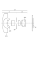
図1、図3、図5は本発明の実施例1乃至3の光学系のレンズ断面図である。図2、図4、図6は実施例1乃至3の光学系の収差図である。 1, 3, and 5 are cross-sectional views of lenses of optical systems according to Examples 1 to 3 of the present invention. 2, 4, and 6 are aberration diagrams of the optical systems of Examples 1 to 3.
実施例1はFナンバー4.0、撮像半画角91度の光学系である。実施例2はFナンバー4.0、撮像半画角91度の光学系である。実施例3はFナンバー4.0、撮像半画角90度の光学系である。 Example 1 is an optical system with an F number of 4.0 and an imaging half angle of view of 91 degrees. Example 2 is an optical system with an F number of 4.0 and an imaging half angle of view of 91 degrees. Example 3 is an optical system with an F number of 4.0 and an imaging half angle of view of 90 degrees.
各実施例の光学系はデジタルスチルカメラ、ビデオカメラ、監視用カメラ、車載カメラなどの撮像装置に用いられる撮像光学系である。レンズ断面図において、左方が物体側(前方)で、右方が像側(後方)である。L0は光学系である。L1は第1レンズ群、L2は第2レンズ群である。 The optical system of each embodiment is an imaging optical system used in an imaging device such as a digital still camera, a video camera, a surveillance camera, or a vehicle-mounted camera. In the cross-sectional view of the lens, the left side is the object side (front), and the right side is the image side (back). L0 is an optical system. L1 is a first lens group, and L2 is a second lens group.
SPは開放Fナンバー(Fno)の光束を決定(制限)する開口絞りである。IPは像面であり、デジタルスチルカメラやビデオカメラの撮影光学系として使用する際にはCCDセンサやCMOSセンサ等の固体撮像素子(光電変換素子)の撮像面が置かれる。 SP is an aperture diaphragm that determines (restricts) the luminous flux of the open F number (Fno). IP is an image plane, and when used as a photographing optical system of a digital still camera or a video camera, the image pickup plane of a solid-state image sensor (photoelectric conversion element) such as a CCD sensor or a CMOS sensor is placed.
収差図においてFnoはFナンバー、ωは撮像半画角(度)であり、光線追跡による画角である。球面収差図において、dはd線(波長587.56nm)、gはg線(波長435.835nm)である。 In the aberration diagram, Fno is the F number, and ω is the imaging half angle of view (degrees), which is the angle of view determined by ray tracing. In the spherical aberration diagram, d is the d-line (wavelength 587.56 nm), and g is the g-line (wavelength 435.835 nm).
非点収差図においてΔSはd線におけるサジタル像面、ΔMはd線におけるメリディオナル像面である。歪曲収差はd線について示している。倍率色収差図においてgはg線である。 In the astigmatism diagram, ΔS is the sagittal image plane for the d-line, and ΔM is the meridional image plane for the d-line. Distortion aberration is shown for the d-line. In the lateral chromatic aberration diagram, g is the g-line.
本発明の各実施例の光学系L0における射影方式は、等立体角射影方式(Y=2・f・sin(θ/2))を採用している。なお、本発明にかかる光学系L0においては、射影方式を等立体角射影に限定すべきものではなく、いかなる射影方式であっても構わない。 The projection method in the optical system L0 of each embodiment of the present invention employs an equal solid angle projection method (Y=2·f·sin(θ/2)). Note that in the optical system L0 according to the present invention, the projection method is not limited to equisolid angle projection, and any projection method may be used.
本発明の光学系L0は、物体側より像側へ順に配置された負の屈折力の第1レンズ群L1、開口絞りSP、正の屈折力の第2レンズ群L2より構成されている。第1レンズ群L1及び第2レンズ群はそれぞれ負レンズを有する。第1レンズ群L1中の最も物体側の負レンズG1Nの焦点距離をfG1Nとする。第2レンズ群中の負の屈折力が最も大きい負レンズGLNの焦点距離をfGLNとする。光学系L0の焦点距離をf、第1レンズ群L1の焦点距離をf1とする。このとき、下記の条件式を満足する。
0.10<fG1N/f1<1.00 ・・・(1)
0.10<|fGLN/f|<2.50 ・・・(2)
The optical system L0 of the present invention includes a first lens group L1 with negative refractive power, an aperture stop SP, and a second lens group L2 with positive refractive power, which are arranged in order from the object side to the image side. The first lens group L1 and the second lens group each have a negative lens. Let fG1N be the focal length of the negative lens G1N closest to the object in the first lens group L1. Let fGLN be the focal length of the negative lens GLN having the largest negative refractive power in the second lens group. The focal length of the optical system L0 is f, and the focal length of the first lens group L1 is f1. At this time, the following conditional expression is satisfied.
0.10<fG1N/f1<1.00...(1)
0.10<|fGLN/f|<2.50...(2)
ここでレンズ全長とは、物体側の第1レンズ面から最も像側のレンズ面までの距離に空気換算のバックフォーカスを加えた値である。一般にレンズ全長を短縮し、光学系全体の小型化を図るほど諸収差、特に倍率色収差などの色収差の発生が多くなり、光学性能が低下してくる。特にレンズ全長の短縮化を図ったレトロフォーカス型の光学系では、負の屈折力の第1レンズ群L1が大型化しやすく、第1レンズ群L1のレンズ構成、屈折力配置等を適切にすることが重要となる。 Here, the total lens length is a value obtained by adding the air-equivalent back focus to the distance from the first lens surface on the object side to the lens surface closest to the image side. Generally, as the overall length of the lens is shortened and the overall optical system is made more compact, various aberrations, especially chromatic aberrations such as chromatic aberration of magnification, occur more frequently, and optical performance deteriorates. In particular, in a retrofocus type optical system that aims to shorten the overall lens length, the first lens group L1 with negative refractive power tends to be large, so it is necessary to appropriate the lens configuration and refractive power arrangement of the first lens group L1. becomes important.
各実施例では、第2レンズ群L2中の負レンズGLNの負の屈折力を適性化することでレンズ全長の短縮化およびバックフォーカスの短縮化を図っている。 In each embodiment, the overall length of the lens and the back focus are shortened by optimizing the negative refractive power of the negative lens GLN in the second lens group L2.
条件式(1)は、第1レンズ群L1における最も物体側の負レンズG1Nの焦点距離を第1レンズ群L1の焦点距離で規定したものであり、光学系L0の小型化と広画角化を図るためのものである。条件式(1)の上限を超えると、倍率色収差の補正には有利だが前玉有効径が大型化してくる。条件式(1)の下限を超えると、像面湾曲や歪曲収差の補正が難しくなり、レンズ枚数が増加し、レンズ全長が増大してくる。 Conditional expression (1) defines the focal length of the negative lens G1N that is closest to the object in the first lens group L1 by the focal length of the first lens group L1, and reduces the size and widens the angle of view of the optical system L0. The purpose is to achieve this goal. Exceeding the upper limit of conditional expression (1) is advantageous for correcting lateral chromatic aberration, but the effective diameter of the front lens becomes larger. When the lower limit of conditional expression (1) is exceeded, it becomes difficult to correct field curvature and distortion, the number of lenses increases, and the total lens length increases.
条件式(2)は、第2レンズ群L2中の負の屈折力が最も大きい負レンズGLNの焦点距離を光学系L0の焦点距離で規定したものであり、バックフォーカスの短縮化とレンズ全長の短縮化を図るためのものである。条件式(2)の上限を超えると、収差補正は容易となるが、バックフォーカスの短縮が難しくなり、レンズ全長が増大して、光学系が大型化してくる。条件式(2)の下限を超えると、軸外のコマ収差の像高変化が大きくなり、像面湾曲や非点収差の補正が難しくなり、レンズ枚数が増加してくるため好ましくない。 Conditional expression (2) defines the focal length of the negative lens GLN, which has the largest negative refractive power in the second lens group L2, as the focal length of the optical system L0, and reduces the back focus and the overall lens length. This is to shorten the time. When the upper limit of conditional expression (2) is exceeded, aberration correction becomes easy, but it becomes difficult to shorten the back focus, the total lens length increases, and the optical system becomes larger. Exceeding the lower limit of conditional expression (2) is not preferable because the change in image height due to off-axis comatic aberration becomes large, it becomes difficult to correct field curvature and astigmatism, and the number of lenses increases.
各実施例では以上説明したように、条件式(1)、(2)を満足するように各要素を適切に設定している。これにより小型で色収差等の諸収差が良好に補正された光学系を得ている。 In each embodiment, as explained above, each element is appropriately set so as to satisfy conditional expressions (1) and (2). This provides a compact optical system in which various aberrations such as chromatic aberration are well corrected.
各実施例において更に好ましくは条件式(1)、(2)の数値範囲を次の如く設定するのが良い。
0.50<fG1N/f1<0.92 ・・・(1a)
1.00<|fGLN/f|<2.40 ・・・(2a)
In each embodiment, it is more preferable to set the numerical ranges of conditional expressions (1) and (2) as follows.
0.50<fG1N/f1<0.92...(1a)
1.00<|fGLN/f|<2.40...(2a)
更に好ましくは条件式(1a)、(2a)の数値範囲を次の如く設定するのが良い。
0.70<fG1N/f1<0.88 ・・・(1b)
2.00<|fGLN/f|<2.30 ・・・(2b)
More preferably, the numerical ranges of conditional expressions (1a) and (2a) are set as follows.
0.70<fG1N/f1<0.88 (1b)
2.00<|fGLN/f|<2.30...(2b)
各実施例では以上のように各レンズ群の構成を適切にし、条件式(1)、(2)を満たすことにより、大口径比で実現し、レンズ系全体が小型で色収差を良好に補正した高い結像性能を有す光学系を得ている。 In each example, as described above, by optimizing the configuration of each lens group and satisfying conditional expressions (1) and (2), a large aperture ratio was achieved, the entire lens system was compact, and chromatic aberration was well corrected. An optical system with high imaging performance has been obtained.
また、負レンズGLNの物体側のレンズ面の曲率半径をR1GLN、負レンズGLNの像側のレンズ面の曲率半径をR2GLNとする。ここで、物体側のレンズ面の曲率半径と、像側のレンズ面の曲率半径は、レンズ面が非球面形状の場合は、そのベースR(基準となる2次曲面の半径)を意味する。負レンズGLNの材料の屈折率をndGLNとする。光学系のレンズ全長をTDとする。 Furthermore, the radius of curvature of the object-side lens surface of the negative lens GLN is R1GLN, and the radius of curvature of the image-side lens surface of the negative lens GLN is R2GLN. Here, the radius of curvature of the lens surface on the object side and the radius of curvature of the lens surface on the image side mean the base R (radius of the reference quadratic curved surface) when the lens surface is aspherical. Let ndGLN be the refractive index of the material of the negative lens GLN. Let the total length of the lens of the optical system be TD.
光学系のバックフォーカスをSKとする。第1レンズ群L1は負レンズG1Nの像側に隣接して配置されて負レンズG2Nを有し、負レンズG2Nの焦点距離をfG2Nとする。第2レンズ群L2の焦点距離をf2とする。第2レンズ群L2は1枚以上の正レンズを有し、第2レンズ群L2に含まれる正レンズの材料のアッベ数の平均値をνdP2とする。なお、材料のアッベ数νdはフラウンホーファ線のd線、F線、C線における屈折率をNd、NF、NCとするとき、
νd=(Nd-1)/(NF-NC)
で定義される。第2レンズ群L2に含まれる負レンズの材料の屈折率の平均値をndN2とする。
Let the back focus of the optical system be SK. The first lens group L1 is disposed adjacent to the image side of the negative lens G1N and has a negative lens G2N, and the focal length of the negative lens G2N is fG2N. Let f2 be the focal length of the second lens group L2. The second lens group L2 has one or more positive lenses, and the average Abbe number of the material of the positive lenses included in the second lens group L2 is νdP2. In addition, the Abbe number νd of the material is when the refractive index at the d line, F line, and C line of Fraunhofer lines is Nd, NF, and NC.
νd=(Nd-1)/(NF-NC)
Defined by Let ndN2 be the average value of the refractive index of the material of the negative lens included in the second lens group L2.
各実施例の光学系によって形成された像を受光する撮像素子を有する撮像装置において、光線追跡による撮像半画角をωとする。 In an imaging device having an image sensor that receives an image formed by the optical system of each embodiment, the imaging half angle of view by ray tracing is assumed to be ω.
このとき次の条件式のうち1以上を満足するのが良い。
1.0<(R2GLN+R1GLN)/
(R2GLN-R1GLN)<6.0 ・・・(3)
1.85<ndGLN<2.40 ・・・(4)
1.0<TD/f<10.0 ・・・(5)
0.5<SK/f<2.6 ・・・(6)
0.30<fG1N/fG2N<0.80 ・・・(7)
-2.0<f1/f2<-1.0 ・・・(8)
75<νdP2<100 ・・・(9)
1.86<ndN2<2.40 ・・・(10)
80°<ω<120° ・・・(11)
At this time, it is preferable that one or more of the following conditional expressions be satisfied.
1.0<(R2GLN+R1GLN)/
(R2GLN-R1GLN)<6.0...(3)
1.85<ndGLN<2.40 (4)
1.0<TD/f<10.0...(5)
0.5<SK/f<2.6...(6)
0.30<fG1N/fG2N<0.80...(7)
-2.0<f1/f2<-1.0...(8)
75<νdP2<100 (9)
1.86<ndN2<2.40 (10)
80°<ω<120°...(11)
次に前述の各条件式の技術的意味について説明する。 Next, the technical meaning of each of the above conditional expressions will be explained.
条件式(3)は、第2レンズ群L2中の負の屈折力が最も大きい負レンズGLNのシェープファクタ(レンズ形状)を規定したもので、主に像面湾曲を良好に補正しつつバックフォーカスの短縮化を図るためのものである。条件式(3)の上限を超えると、負レンズGLNのメニスカス形状が強くなり、所望の屈折力を確保することが難しくなり、レンズ全長が増大するため好ましくない、また、負レンズGLNの製造が難しくなる。条件式(3)の下限を超えると、歪曲収差がプラス側方向に強く発生しやすくなり好ましくない、また、像面湾曲補正と倍率色収差補正の両立が難しくなる。 Conditional expression (3) specifies the shape factor (lens shape) of the negative lens GLN, which has the largest negative refractive power in the second lens group L2, and mainly corrects the curvature of field while achieving back focus. This is to shorten the time period. If the upper limit of conditional expression (3) is exceeded, the meniscus shape of the negative lens GLN becomes strong, making it difficult to secure the desired refractive power, increasing the overall length of the lens, which is not preferable, and making it difficult to manufacture the negative lens GLN. It becomes difficult. If the lower limit of conditional expression (3) is exceeded, distortion tends to occur strongly in the positive direction, which is undesirable, and it becomes difficult to achieve both field curvature correction and magnification chromatic aberration correction.
条件式(4)は、第2レンズ群L2中の負の屈折力が最も大きい負レンズGLNの材料の屈折率を規定したものである。光学材料の特性上、屈折率が大きくなるにつれて、アッベ数が小さくなり、倍率色収差が補正不足になってくる。このため、色収差を補正しようとすると屈折力を弱くせざるを得ず、レンズ全長が増大する。 Conditional expression (4) defines the refractive index of the material of the negative lens GLN, which has the largest negative refractive power in the second lens group L2. Due to the characteristics of optical materials, as the refractive index increases, the Abbe number decreases and lateral chromatic aberration becomes undercorrected. Therefore, in order to correct chromatic aberration, the refractive power must be weakened, which increases the overall length of the lens.
また、レトロフォーカス型の光学系において、構成レンズ枚数を少なくし小型化を図った場合、ペッツバール和が負の値となりやすく、像面がオーバー側へ倒れ、非点隔差が大きくなってくる。そのため、負レンズの材料の屈折率を適性化し、像面湾曲や非点隔差を良好に補正することが重要となる。 Furthermore, in a retrofocus optical system, when the number of constituent lenses is reduced to reduce the size, the Petzval sum tends to take a negative value, the image plane tilts toward the overside, and the astigmatism difference becomes large. Therefore, it is important to optimize the refractive index of the material of the negative lens to satisfactorily correct field curvature and astigmatism.
条件式(4)の上限を超えると、像面の補正は容易となるが、歪曲収差と倍率色収差の補正が困難になってくる。条件式(4)の下限を超えると、像面湾曲を補正するために負レンズGLNの材料の屈折力を弱める必要があり、その結果バックフォーカスが増大するため、好ましくない。 When the upper limit of conditional expression (4) is exceeded, it becomes easy to correct the image plane, but it becomes difficult to correct distortion aberration and lateral chromatic aberration. Exceeding the lower limit of conditional expression (4) is not preferable because it is necessary to weaken the refractive power of the material of the negative lens GLN in order to correct field curvature, and as a result, back focus increases.
条件式(5)は、レンズ全長TDを光学系L0の焦点距離fで規定し、主に光学系を小型化しつつ、軸外収差の補正を良好に行うためのものである。条件式(5)の上限を超えると、光学系全体が大型化し、軸外収差の補正、特にサジタル方向のコマフレアーが増加し好ましくない。条件式(5)の下限を超えると、レンズ全長が短くなり、コマ収差や像面湾曲といった諸収差の補正が困難になる。 Conditional expression (5) defines the lens total length TD by the focal length f of the optical system L0, and is mainly used to downsize the optical system while properly correcting off-axis aberrations. If the upper limit of conditional expression (5) is exceeded, the entire optical system becomes larger, and correction of off-axis aberrations, especially coma flare in the sagittal direction, increases, which is not preferable. When the lower limit of conditional expression (5) is exceeded, the total lens length becomes short, making it difficult to correct various aberrations such as coma and curvature of field.
条件式(6)は、バックフォーカスSKを光学系L0の焦点距離fで規定し、所謂レトロ比を定義したものである。条件式(6)の上限を超えて、バックフォーカスが長くなると、歪曲収差や像面湾曲の補正が難しくなり、レンズ枚数が増加してくるため好ましくない。条件式(6)の下限を超えて、バックフォーカスが短くなると、像側にシャッター部材等の配置が難しくなる。 Conditional expression (6) defines the back focus SK by the focal length f of the optical system L0, and defines a so-called retro ratio. If the back focus becomes longer than the upper limit of conditional expression (6), it becomes difficult to correct distortion aberration and curvature of field, and the number of lenses increases, which is not preferable. If the lower limit of conditional expression (6) is exceeded and the back focus becomes short, it becomes difficult to arrange a shutter member or the like on the image side.
条件式(7)は、負レンズG1Nの屈折力と負レンズG2Nの屈折力の分担を規定したものである。条件式(7)は光学系の小型化を図りつつ、広画角化を図るために物体側から像側に順に2枚の負レンズを配置し、その屈折力の分担を規定している。条件式(7)の上限を超えて、最も物体側の負レンズG1Nの負の屈折力が弱くなると(負の屈折力の絶対値が小さくなると)、前玉有効径が増加してくる。条件式(7)の下限を超えて、最も物体側の負レンズG1Nの負の屈折力が強くなると(負の屈折力の絶対値が大きくなると)、光学系の小型化には有利となるが、像面湾曲や非点収差の補正が難しくなる。 Conditional expression (7) defines the sharing of the refractive power of the negative lens G1N and the refractive power of the negative lens G2N. Conditional expression (7) stipulates that two negative lenses are arranged in order from the object side to the image side, and their refractive power is shared, in order to make the optical system more compact and widen the angle of view. When the upper limit of conditional expression (7) is exceeded and the negative refractive power of the negative lens G1N closest to the object becomes weaker (as the absolute value of the negative refractive power becomes smaller), the effective diameter of the front lens increases. If the lower limit of conditional expression (7) is exceeded and the negative refractive power of the negative lens G1N closest to the object becomes stronger (the absolute value of the negative refractive power becomes larger), it will be advantageous for downsizing the optical system. , it becomes difficult to correct field curvature and astigmatism.
条件式(8)は、負の屈折力の第1レンズ群L1の焦点距離f1を正の屈折力の第2レンズ群L2の焦点距離f2で規定したものである。条件式(8)の上限を超て第1レンズ群L1の負の屈折力が強くなると、マージナル光線の発散作用が大きくなり、第2レンズ群L2において球面収差やコマ収差の補正が難しくなる。条件式(8)の下限を超えて第2レンズ群L2の正の屈折力が強くなると第2レンズ群L2の収斂作用が大きくなり、倍率色収差と軸上色収差の二次スペクトルを補正することが難しくなり好ましくない。 Conditional expression (8) defines the focal length f1 of the first lens group L1 with negative refractive power as the focal length f2 of the second lens group L2 with positive refractive power. When the negative refractive power of the first lens group L1 becomes strong beyond the upper limit of conditional expression (8), the divergence effect of the marginal ray becomes large, making it difficult to correct spherical aberration and coma aberration in the second lens group L2. When the lower limit of conditional expression (8) is exceeded and the positive refractive power of the second lens group L2 becomes stronger, the convergence effect of the second lens group L2 increases, making it possible to correct the secondary spectrum of lateral chromatic aberration and longitudinal chromatic aberration. It becomes difficult and I don't like it.
条件式(9)は、第2レンズ群L2に含まれる正レンズの材料のアッベ数の平均値νdP2を規定したものであり、主にレンズ全長を短縮化しつつ軸上色収差、倍率色収差を良好に補正するためのものである。条件式(9)の上限を超えると、軸上色収差、倍率色収差の補正は容易となるが、各レンズのレンズ面の曲率半径が増大し、球面収差やコマ収差が補正不足となり好ましくない。条件式(9)の下限を超えると、色収差が増大し、光学系全体としての収差補正が困難になる。 Conditional expression (9) defines the average value νdP2 of the Abbe number of the material of the positive lens included in the second lens group L2, and mainly aims to reduce the overall length of the lens while improving longitudinal chromatic aberration and lateral chromatic aberration. This is for correction. If the upper limit of conditional expression (9) is exceeded, it becomes easy to correct axial chromatic aberration and lateral chromatic aberration, but the radius of curvature of the lens surface of each lens increases, resulting in insufficient correction of spherical aberration and coma aberration, which is not preferable. When the lower limit of conditional expression (9) is exceeded, chromatic aberration increases, making it difficult to correct the aberration of the optical system as a whole.
条件式(10)は、第2レンズ群L2に含まれる負レンズの材料の屈折率の平均値ndN2を規定したものであり、主に像面湾曲と歪曲収差を良好に補正するためのものである。条件式(10)の上限を超えると、光学系の小型化は容易となるが倍率色収差の補正が困難になる。条件式(10)の下限を超えると、像面湾曲の補正が難しくなる。 Conditional expression (10) defines the average value ndN2 of the refractive index of the material of the negative lens included in the second lens group L2, and is mainly used to satisfactorily correct curvature of field and distortion aberration. be. When the upper limit of conditional expression (10) is exceeded, it becomes easy to downsize the optical system, but it becomes difficult to correct lateral chromatic aberration. If the lower limit of conditional expression (10) is exceeded, it becomes difficult to correct the curvature of field.
条件式(11)は、各実施例の光学系によって形成された像を受光する撮像素子を有する撮像装置において、光線追跡による撮像半画角ωを規定したものである。条件式(11)の上限を超えて、最大の撮像半画角が大きくなると、各画角の像圧縮が高くなり、十分な解像力を得ることが難しくなる。条件式(11)の下限を超えると、円周魚眼レンズとして必要な画角を得ることが困難となる。 Conditional expression (11) defines the imaging half angle of view ω by ray tracing in an imaging device having an imaging element that receives an image formed by the optical system of each embodiment. If the maximum imaging half angle of view increases beyond the upper limit of conditional expression (11), image compression for each angle of view becomes high, making it difficult to obtain sufficient resolution. If the lower limit of conditional expression (11) is exceeded, it becomes difficult to obtain the angle of view necessary for a circumferential fisheye lens.
好ましくは条件式(3)乃至(10)の数値範囲を次の如く設定するのが良い。
1.3<(R2GLN+R1GLN)/(R2GLN-R1GLN)<3.0・・・(3a)
1.95<ndGLN<2.20 ・・・(4a)
3.0<TD/f<8.0 ・・・(5a)
1.2<SK/f<2.4 ・・・(6a)
0.35<fG1N/fG2N<0.70 ・・・(7a)
-1.6<f1/f2<-1.1 ・・・(8a)
80<νdP2<95 ・・・(9a)
1.90<ndN2<2.10 ・・・(10a)
Preferably, the numerical ranges of conditional expressions (3) to (10) are set as follows.
1.3<(R2GLN+R1GLN)/(R2GLN-R1GLN)<3.0...(3a)
1.95<ndGLN<2.20...(4a)
3.0<TD/f<8.0...(5a)
1.2<SK/f<2.4...(6a)
0.35<fG1N/fG2N<0.70...(7a)
-1.6<f1/f2<-1.1...(8a)
80<νdP2<95...(9a)
1.90<ndN2<2.10...(10a)
さらに好ましくは条件式(3a)乃至(10a)の数値範囲を次の如く設定するのが良い。
1.6<(R2GLN+R1GLN)/(R2GLN-R1GLN)<2.0・・・(3b)
2.00<ndGLN<2.10 ・・・(4b)
6.0<TD/f<7.0 ・・・(5b)
1.6<SK/f<2.2 ・・・(6b)
0.40<fG1N/fG2N<0.60 ・・・(7b)
-1.4<f1/f2<-1.2 ・・・(8b)
85<νdP2<92 ・・・(9b)
1.92<ndN2<1.98 ・・・(10b)
More preferably, the numerical ranges of conditional expressions (3a) to (10a) are set as follows.
1.6<(R2GLN+R1GLN)/(R2GLN-R1GLN)<2.0...(3b)
2.00<ndGLN<2.10...(4b)
6.0<TD/f<7.0...(5b)
1.6<SK/f<2.2...(6b)
0.40<fG1N/fG2N<0.60...(7b)
-1.4<f1/f2<-1.2...(8b)
85<νdP2<92...(9b)
1.92<ndN2<1.98...(10b)
以上のように本発明によれば、全系が小型で色収差を良好に補正し高い光学性能の光学系を得ることができる。 As described above, according to the present invention, it is possible to obtain an optical system in which the entire system is compact, corrects chromatic aberration well, and has high optical performance.
なお、各実施例の光学系において、第1レンズ群L1は負レンズG1Nを含む少なくとも2枚の負レンズを有することが好ましい。これにより、光学系の広画角化が容易になる。 In addition, in the optical system of each example, it is preferable that the first lens group L1 has at least two negative lenses including the negative lens G1N. This facilitates widening the angle of view of the optical system.
なお、各実施例の光学系において最も像側のレンズ面は像側に凸形状となっていることが好ましい。これにより、撮像面で反射した光によるゴーストを低減することが可能となる。 In addition, in the optical system of each example, it is preferable that the lens surface closest to the image side has a convex shape toward the image side. This makes it possible to reduce ghosts caused by light reflected on the imaging surface.
また、各実施例の光学系は8枚以下のレンズで構成されていることが好ましい。これにより、必要な光学性能を得つつ光学系を小型、軽量に構成することが可能となる。 Further, it is preferable that the optical system of each embodiment is composed of eight or fewer lenses. This makes it possible to configure the optical system to be compact and lightweight while obtaining the necessary optical performance.
また、各実施例の光学系は、第1レンズ群L1と第2レンズ群L2との間に開口絞りを有すことが望ましい。第1レンズ群L1は物体側から像側へ順に配置された負レンズ、負レンズ、正レンズより構成するのが良い。また、第2レンズ群L2は物体側から像側へ順に配置された正レンズ、負レンズ、正レンズ、負レンズより構成するのが良い。また、第2レンズ群L2は物体側から像側へ順に配置された正レンズ、負レンズ、正レンズ、負レンズ、正レンズより構成するのが良い。 Further, it is desirable that the optical system of each embodiment has an aperture stop between the first lens group L1 and the second lens group L2. The first lens group L1 is preferably composed of a negative lens, a negative lens, and a positive lens arranged in order from the object side to the image side. Further, the second lens group L2 is preferably composed of a positive lens, a negative lens, a positive lens, and a negative lens arranged in order from the object side to the image side. Further, the second lens group L2 is preferably composed of a positive lens, a negative lens, a positive lens, a negative lens, and a positive lens arranged in order from the object side to the image side.
なお、各実施例ではいわゆる単焦点レンズについて述べたが、本発明はこれに限定されない。本発明の光学系としては焦点距離が可変であるズームレンズであっても良い。その場合、各条件式はズームレンズの広角端において満足していればよい。 Although each embodiment describes a so-called single focus lens, the present invention is not limited thereto. The optical system of the present invention may be a zoom lens with a variable focal length. In that case, each conditional expression only needs to be satisfied at the wide-angle end of the zoom lens.
次に本発明の光学系を用いたデジタルスチルカメラ(撮像装置)を図7を用いて説明する。図7において、10はカメラ本体、11は実施例1乃至3に説明したいずれかの光学系によって構成された撮像光学系である。12はカメラ本体に内蔵され、撮像光学系11によって形成された被写体像を受光するCCDセンサやCMOSセンサ等の撮像素子(光電変換素子)である。
Next, a digital still camera (imaging device) using the optical system of the present invention will be described with reference to FIG. In FIG. 7, 10 is a camera body, and 11 is an imaging optical system configured by any of the optical systems described in Examples 1 to 3.
以下、実施例1乃至3の具体的な数値データを示す。各数値データにおいて、iは物体側から数えた順序を示し、riは第i番目の光学面(第i面)の曲率半径、diは第i面と第(i+1)面との間の軸上間隔を示す。また、ndi、νdiはそれぞれd線に対する第i番目の光学部材の材料の屈折率、アッベ数である。非球面形状は光軸方向にX軸、光軸と垂直方向にH軸、光の進行方向を正としRを近軸曲率半径、Kを円錐定数、A4、A6、A8を各々非球面係数としたとき Specific numerical data of Examples 1 to 3 will be shown below. In each numerical data, i indicates the order counted from the object side, ri is the radius of curvature of the i-th optical surface (i-th surface), and di is on the axis between the i-th surface and the (i+1)-th surface. Indicates the interval. Further, ndi and vdi are the refractive index and Abbe number of the material of the i-th optical member with respect to the d-line, respectively. The aspherical shape has the X axis in the optical axis direction, the H axis in the direction perpendicular to the optical axis, the direction of light travel as positive, R is the paraxial radius of curvature, K is the conic constant, and A4, A6, and A8 are each the aspherical coefficients. when

なる式で表している。*は非球面形状を有する面を意味している。「e-x」は10-xを意味している。BFは空気換算のバックフォーカスである。また、前述の各条件式に関するパラメータと各条件式に対する数値データとの関係を表1に示す。 It is expressed by the following formula. * means a surface having an aspherical shape. "ex" means 10 -x . BF is back focus in terms of air. Further, Table 1 shows the relationship between the parameters regarding each of the above-mentioned conditional expressions and the numerical data for each conditional expression.
[数値データ1]
単位 mm
面データ
面番号 r d nd νd θgF
1 48.855 2.20 1.76385 48.49 0.5589
2 11.031 8.00
3 13.330 1.50 1.53775 74.70 0.5392
4 8.150 7.29
5 -48.351 6.58 1.85025 30.05 0.5979
6 -26.933 4.00
7(絞り) ∞ 4.00
8* -38.065 5.26 1.49710 81.56 0.5377
9* -9.535 1.12
10 12.869 1.50 1.85025 30.05 0.5979
11 9.695 9.98 1.43700 95.10 0.5326
12 -12.615 1.50 2.05090 26.94 0.6054
13 -38.769 11.72
14 ∞ 1.50 1.51633 64.14 0.5353
15 ∞ 0.50
像面 ∞
非球面データ
第8面
K = 6.24411e+001 A 4=-1.54425e-004 A 6=-3.30729e-006
第9面
K = 9.25963e-001 A 4= 4.65880e-005 A 6=-1.63395e-008 A 8= 4.39179e-009
各種データ
焦点距離 8.10
Fナンバー 4.00
半画角(度) 90.84
像高 11.50
レンズ全長 66.13
BF 13.21
群データ
群 始面 焦点距離 レンズ構成長 前側主点位置 後側主点位置
1 1 -21.96 25.56 -2.21 -32.37
2 7 17.16 23.36 5.35 -10.27
単レンズデータ
レンズ 始面 焦点距離
1 1 -19.13
2 3 -43.40
3 5 62.67
4 8 24.12
5 10 -59.04
6 11 14.52
7 12 -18.33
[Numerical data 1]
Unit: mm
Surface data surface number rd nd νd θgF
1 48.855 2.20 1.76385 48.49 0.5589
2 11.031 8.00
3 13.330 1.50 1.53775 74.70 0.5392
4 8.150 7.29
5 -48.351 6.58 1.85025 30.05 0.5979
6 -26.933 4.00
7(Aperture) ∞ 4.00
8* -38.065 5.26 1.49710 81.56 0.5377
9* -9.535 1.12
10 12.869 1.50 1.85025 30.05 0.5979
11 9.695 9.98 1.43700 95.10 0.5326
12 -12.615 1.50 2.05090 26.94 0.6054
13 -38.769 11.72
14 ∞ 1.50 1.51633 64.14 0.5353
15 ∞ 0.50
Image plane ∞
Aspheric data 8th surface
K = 6.24411e+001 A 4=-1.54425e-004 A 6=-3.30729e-006
9th page
K = 9.25963
Various data
Focal length 8.10
F number 4.00
Half angle of view (degrees) 90.84
Image height 11.50
Lens total length 66.13
BF 13.21
Group data group Starting plane Focal length Lens length Front principal point position Rear principal point position
1 1 -21.96 25.56 -2.21 -32.37
2 7 17.16 23.36 5.35 -10.27
Single lens data lens starting surface focal length
1 1 -19.13
2 3 -43.40
3 5 62.67
4 8 24.12
5 10 -59.04
6 11 14.52
7 12 -18.33
[数値データ2]
単位 mm
面データ
面番号 r d nd νd θgF
1 49.348 2.20 1.77250 49.60 0.5520
2 11.602 8.36
3 16.043 1.50 1.59522 67.74 0.5442
4 8.639 8.43
5 -127.111 7.34 1.85025 30.05 0.5979
6 -32.443 4.00
7(絞り) ∞ 4.00
8* -37.935 5.08 1.49710 81.56 0.5377
9* -9.832 1.12
10 12.990 1.50 1.85025 30.05 0.5979
11 10.208 7.08 1.43700 95.10 0.5326
12 -11.612 1.50 2.00100 29.13 0.5997
13 -37.657 14.46
14 ∞ 1.50 1.51633 64.14 0.5353
15 ∞ 0.50
像面 ∞
非球面データ
第8面
K = 6.25847e+001 A 4=-1.19636e-004 A 6=-1.68125e-006
第9面
K = 1.14514e+000 A 4= 6.06644e-005 A 6=-4.08608e-008 A 8= 2.18193e-008
各種データ
焦点距離 8.05
Fナンバー 4.00
半画角(度) 90.96
像高 11.50
レンズ全長 68.06
BF 15.95
群データ
群 始面 焦点距離 レンズ構成長 前側主点位置 後側主点位置
1 1 -25.02 27.82 -4.13 -40.41
2 7 18.32 20.28 5.83 -8.26
単レンズデータ
レンズ 始面 焦点距離
1 1 -20.15
2 3 -34.02
3 5 49.47
4 8 25.19
5 10 -74.51
6 11 13.79
7 12 -17.27
[Numerical data 2]
Unit: mm
Surface data surface number rd nd νd θgF
1 49.348 2.20 1.77250 49.60 0.5520
2 11.602 8.36
3 16.043 1.50 1.59522 67.74 0.5442
4 8.639 8.43
5 -127.111 7.34 1.85025 30.05 0.5979
6 -32.443 4.00
7(Aperture) ∞ 4.00
8* -37.935 5.08 1.49710 81.56 0.5377
9* -9.832 1.12
10 12.990 1.50 1.85025 30.05 0.5979
11 10.208 7.08 1.43700 95.10 0.5326
12 -11.612 1.50 2.00100 29.13 0.5997
13 -37.657 14.46
14 ∞ 1.50 1.51633 64.14 0.5353
15 ∞ 0.50
Image plane ∞
Aspheric data 8th surface
K = 6.25847e+001 A 4=-1.19636e-004 A 6=-1.68125e-006
9th page
K = 1.14514e+000 A 4= 6.06644e-005 A 6=-4.08608e-008 A 8= 2.18193e-008
Various data
Focal length 8.05
F number 4.00
Half angle of view (degrees) 90.96
Image height 11.50
Lens total length 68.06
BF 15.95
Group data group Starting plane Focal length Lens length Front principal point position Rear principal point position
1 1 -25.02 27.82 -4.13 -40.41
2 7 18.32 20.28 5.83 -8.26
Single lens data lens starting surface focal length
1 1 -20.15
2 3 -34.02
3 5 49.47
4 8 25.19
5 10 -74.51
6 11 13.79
7 12 -17.27
[数値データ3]
単位 mm
面データ
面番号 r d nd νd θgF
1 47.043 2.20 1.75500 52.32 0.5474
2 10.972 8.05
3 16.238 1.50 1.59282 68.63 0.5446
4 8.975 8.46
5 -56.618 6.70 1.85025 30.05 0.5979
6 -25.741 4.00
7(絞り) ∞ 4.00
8* -36.732 6.16 1.49710 81.56 0.5377
9* -10.650 1.12
10 16.329 1.40 1.85025 30.05 0.5979
11 14.422 6.07 1.43700 95.10 0.5326
12 -13.895 0.24
13 -12.740 1.10 2.00330 28.27 0.5980
14 -50.712 0.25
15 -625.576 2.25 1.43700 95.10 0.5326
16 -26.985 15.44
17 ∞ 1.50 1.51633 64.14 0.5353
18 ∞ 0.50
像面 ∞
非球面データ
第8面
K = 5.26909e+001 A 4=-5.71261e-005 A 6= 4.12322e-007
第9面
K = 1.08114e+000 A 4= 5.10417e-005 A 6= 3.13406e-007 A 8= 8.03706e-009
各種データ
焦点距離 8.05
Fナンバー 4.00
半画角(度) 90.07
像高 11.40
レンズ全長 70.43
BF 16.93
群データ
群 始面 焦点距離 レンズ構成長 前側主点位置 後側主点位置
1 1 -26.07 26.92 -5.08 -42.53
2 7 19.16 22.59 8.62 -8.15
単レンズデータ
レンズ 始面 焦点距離
1 1 -19.46
2 3 -36.67
3 5 50.48
4 8 27.98
5 10 -219.23
6 11 17.32
7 13 -17.21
8 15 64.46
[Numerical data 3]
Unit: mm
Surface data surface number rd nd νd θgF
1 47.043 2.20 1.75500 52.32 0.5474
2 10.972 8.05
3 16.238 1.50 1.59282 68.63 0.5446
4 8.975 8.46
5 -56.618 6.70 1.85025 30.05 0.5979
6 -25.741 4.00
7(Aperture) ∞ 4.00
8* -36.732 6.16 1.49710 81.56 0.5377
9* -10.650 1.12
10 16.329 1.40 1.85025 30.05 0.5979
11 14.422 6.07 1.43700 95.10 0.5326
12 -13.895 0.24
13 -12.740 1.10 2.00330 28.27 0.5980
14 -50.712 0.25
15 -625.576 2.25 1.43700 95.10 0.5326
16 -26.985 15.44
17 ∞ 1.50 1.51633 64.14 0.5353
18 ∞ 0.50
Image plane ∞
Aspheric data 8th surface
K = 5.26909e+001 A 4=-5.71261e-005 A 6= 4.12322e-007
9th page
K = 1.08114e+000 A 4= 5.10417e-005 A 6= 3.13406e-007 A 8= 8.03706e-009
Various data
Focal length 8.05
F number 4.00
Half angle of view (degrees) 90.07
Image height 11.40
Lens total length 70.43
BF 16.93
Group data group Starting plane Focal length Lens length Front principal point position Rear principal point position
1 1 -26.07 26.92 -5.08 -42.53
2 7 19.16 22.59 8.62 -8.15
Single lens data lens starting surface focal length
1 1 -19.46
2 3 -36.67
3 5 50.48
4 8 27.98
5 10 -219.23
6 11 17.32
7 13 -17.21
8 15 64.46

L1 第1レンズ群
L2 第2レンズ群
SP 開口絞り
L1 1st lens group L2 2nd lens group SP Aperture diaphragm
Claims (13)
該光学系は、屈折力を有するレンズを6枚以上有し、
前記第1レンズ群は、前記第1レンズ群の最も物体側に配置された負レンズG1Nと、前記負レンズG1Nの像側に隣り合って配置された負レンズG2Nを有し、
前記第2レンズ群は少なくとも1枚の負レンズと、少なくとも1枚の正レンズを有し、
前記負レンズG1Nの焦点距離をfG1N、前記第2レンズ群において負の屈折力が最も大きい負レンズGLNの焦点距離をfGLN、前記光学系の焦点距離をf、前記第1レンズ群の焦点距離をf1、前記負レンズG2Nの焦点距離をfG2N、前記第2レンズ群の焦点距離をf2、前記第2レンズ群に含まれる全ての正レンズの材料のアッベ数の平均値をνdP2とするとき、
0.70<fG1N/f1<1.0
2.00<|fGLN/f|<2.5
0.441≦fG1N/fG2N<0.80
-2.0<f1/f2<-1.0
75<νdP2<100
なる条件式を満足することを特徴とする光学系。 In an optical system that includes a first lens group with negative refractive power, an aperture stop, and a second lens group with positive refractive power, which are arranged in order from the object side to the image side,
The optical system has six or more lenses having refractive power,
The first lens group includes a negative lens G1N disposed closest to the object side of the first lens group, and a negative lens G2N disposed adjacent to the negative lens G1N on the image side,
The second lens group includes at least one negative lens and at least one positive lens ,
The focal length of the negative lens G1N is fG1N, the focal length of the negative lens GLN with the largest negative refractive power in the second lens group is fGLN, the focal length of the optical system is f, and the focal length of the first lens group is f1, the focal length of the negative lens G2N is fG2N, the focal length of the second lens group is f2, and the average value of the Abbe numbers of the materials of all the positive lenses included in the second lens group is νdP2,
0.70<fG1N/f1<1.0
2.00<|fGLN/f|<2.5
0.441≦fG1N/fG2N<0.80
-2.0<f1/f2<-1.0
75<νdP2<100
An optical system characterized by satisfying the following conditional expression.
1.0<(R2GLN+R1GLN)/(R2GLN-R1GLN)<6.0
なる条件式を満足することを特徴とする請求項1に記載の光学系。 When the radius of curvature of the object-side lens surface of the negative lens GLN is R1GLN, and the radius of curvature of the image-side lens surface of the negative lens GLN is R2GLN,
1.0<(R2GLN+R1GLN)/(R2GLN-R1GLN)<6.0
The optical system according to claim 1, wherein the optical system satisfies the following conditional expression.
該光学系は、屈折力を有するレンズを6枚以上有し、The optical system has six or more lenses having refractive power,
前記第1レンズ群は、前記第1レンズ群の最も物体側に配置された負レンズG1Nと、前記負レンズG1Nの像側に隣り合って配置された負レンズG2Nを有し、The first lens group includes a negative lens G1N disposed closest to the object side of the first lens group, and a negative lens G2N disposed adjacent to the negative lens G1N on the image side,
前記第2レンズ群は少なくとも1枚の負レンズを有し、The second lens group includes at least one negative lens,
前記負レンズG1Nの焦点距離をfG1N、前記第2レンズ群において負の屈折力が最も大きい負レンズGLNの焦点距離をfGLN、前記光学系の焦点距離をf、前記第1レンズ群の焦点距離をf1、前記負レンズG2Nの焦点距離をfG2N、前記第2レンズ群の焦点距離をf2、前記負レンズGLNの物体側のレンズ面の曲率半径をR1GLN、前記負レンズGLNの像側のレンズ面の曲率半径をR2GLNとするとき、The focal length of the negative lens G1N is fG1N, the focal length of the negative lens GLN having the largest negative refractive power in the second lens group is fGLN, the focal length of the optical system is f, and the focal length of the first lens group is f1, the focal length of the negative lens G2N is fG2N, the focal length of the second lens group is f2, the radius of curvature of the object side lens surface of the negative lens GLN is R1GLN, the image side lens surface of the negative lens GLN is When the radius of curvature is R2GLN,
0.70<fG1N/f1<1.00.70<fG1N/f1<1.0
2.00<|fGLN/f|<2.52.00<|fGLN/f|<2.5
0.441≦fG1N/fG2N<0.800.441≦fG1N/fG2N<0.80
-2.0<f1/f2<-1.0-2.0<f1/f2<-1.0
1.0<(R2GLN+R1GLN)/(R2GLN-R1GLN)<6.01.0<(R2GLN+R1GLN)/(R2GLN-R1GLN)<6.0
なる条件式を満足することを特徴とする光学系。An optical system characterized by satisfying the following conditional expression.
1.85<ndGLN<2.40
なる条件式を満足することを特徴とする請求項1乃至3のいずれか1項に記載の光学系。 When the refractive index of the material of the negative lens GLN is ndGLN,
1.85<ndGLN<2.40
4. The optical system according to claim 1, wherein the optical system satisfies the following conditional expression.
1.0<TD/f<10.0
なる条件式を満足することを特徴とする請求項1乃至4のいずれか1項に記載の光学系。 When the total lens length of the optical system is TD,
1.0<TD/f<10.0
5. The optical system according to claim 1, wherein the optical system satisfies the following conditional expression.
0.5<SK/f<2.6
なる条件式を満足することを特徴とする請求項1乃至5のいずれか1項に記載の光学系。 When the back focus of the optical system is SK,
0.5<SK/f<2.6
6. The optical system according to claim 1, wherein the optical system satisfies the following conditional expression.
1.86<ndN2<2.40
なる条件式を満足することを特徴とする請求項1乃至6のいずれか1項に記載の光学系。 When the average value of the refractive index of the material of the negative lens included in the second lens group is ndN2,
1.86<ndN2<2.40
7. The optical system according to claim 1, wherein the optical system satisfies the following conditional expression.
80°<ω<120°
なる条件式を満足することを特徴とする撮像装置。 It has the optical system according to any one of claims 1 to 12 and an image sensor that receives an image formed by the optical system, and when the imaging half angle of view by ray tracing is ω,
80°<ω<120°
An imaging device characterized by satisfying the following conditional expression.
Priority Applications (1)
| Application Number | Priority Date | Filing Date | Title |
|---|---|---|---|
| US16/587,534 US11150467B2 (en) | 2018-10-01 | 2019-09-30 | Optical system and image pickup apparatus including the same consisting of two lens units of −+ refractive powers having seven lenses of −−++−+− refractive powers or eighth lenses of −−++−+−+ refractive powers |
Applications Claiming Priority (2)
| Application Number | Priority Date | Filing Date | Title |
|---|---|---|---|
| JP2018186423 | 2018-10-01 | ||
| JP2018186423 | 2018-10-01 |
Publications (3)
| Publication Number | Publication Date |
|---|---|
| JP2020056995A JP2020056995A (en) | 2020-04-09 |
| JP2020056995A5 JP2020056995A5 (en) | 2022-06-27 |
| JP7387312B2 true JP7387312B2 (en) | 2023-11-28 |
Family
ID=70107237
Family Applications (1)
| Application Number | Title | Priority Date | Filing Date |
|---|---|---|---|
| JP2019126339A Active JP7387312B2 (en) | 2018-10-01 | 2019-07-05 | Optical system and imaging device including it |
Country Status (1)
| Country | Link |
|---|---|
| JP (1) | JP7387312B2 (en) |
Citations (15)
| Publication number | Priority date | Publication date | Assignee | Title |
|---|---|---|---|---|
| JP2008107391A (en) | 2006-10-23 | 2008-05-08 | Olympus Medical Systems Corp | Object optical system for endoscope |
| JP2009047982A (en) | 2007-08-21 | 2009-03-05 | Olympus Imaging Corp | Imaging optical system and electronic imaging apparatus having the same |
| JP2010176015A (en) | 2009-01-30 | 2010-08-12 | Nikon Corp | Wide-angle lens, imaging apparatus, and method for manufacturing the wide angle-lens |
| JP2010276923A (en) | 2009-05-29 | 2010-12-09 | Fujifilm Corp | Objective lens for endoscope, and endoscope |
| JP2011145315A (en) | 2010-01-12 | 2011-07-28 | Fujifilm Corp | Imaging lens, imaging optical system and imaging apparatus |
| JP2011150196A (en) | 2010-01-22 | 2011-08-04 | Nikon Corp | Wide-angle lens, imaging apparatus, and method for manufacturing the wide-angle lens |
| JP2012058406A (en) | 2010-09-07 | 2012-03-22 | Olympus Imaging Corp | Imaging optics and electronic image pickup device having the same |
| JP2013020073A (en) | 2011-07-11 | 2013-01-31 | Sigma Corp | Super-wide angle lens system |
| JP2016014754A (en) | 2014-07-02 | 2016-01-28 | 富士フイルム株式会社 | Endoscope objective lens and endoscope |
| JP2016151629A (en) | 2015-02-17 | 2016-08-22 | 富士フイルム株式会社 | Endoscope objective lens and endoscope |
| JP2017054107A (en) | 2015-09-08 | 2017-03-16 | Hoya株式会社 | Variable power optical system and image capturing device including the same |
| WO2017043352A1 (en) | 2015-09-07 | 2017-03-16 | Hoya株式会社 | Variable power optical system for endoscope, and endoscope |
| JP2017181857A (en) | 2016-03-31 | 2017-10-05 | 日本電産サンキョー株式会社 | Wide-angle lens |
| US20180031807A1 (en) | 2016-07-28 | 2018-02-01 | Largan Precision Co., Ltd. | Optical imaging lens assembly, image capturing apparatus and electronic device |
| JP2018136487A (en) | 2017-02-23 | 2018-08-30 | キヤノン株式会社 | Imaging apparatus |
Family Cites Families (1)
| Publication number | Priority date | Publication date | Assignee | Title |
|---|---|---|---|---|
| JP3765500B2 (en) * | 1993-12-24 | 2006-04-12 | オリンパス株式会社 | Endoscope objective lens |
-
2019
- 2019-07-05 JP JP2019126339A patent/JP7387312B2/en active Active
Patent Citations (15)
| Publication number | Priority date | Publication date | Assignee | Title |
|---|---|---|---|---|
| JP2008107391A (en) | 2006-10-23 | 2008-05-08 | Olympus Medical Systems Corp | Object optical system for endoscope |
| JP2009047982A (en) | 2007-08-21 | 2009-03-05 | Olympus Imaging Corp | Imaging optical system and electronic imaging apparatus having the same |
| JP2010176015A (en) | 2009-01-30 | 2010-08-12 | Nikon Corp | Wide-angle lens, imaging apparatus, and method for manufacturing the wide angle-lens |
| JP2010276923A (en) | 2009-05-29 | 2010-12-09 | Fujifilm Corp | Objective lens for endoscope, and endoscope |
| JP2011145315A (en) | 2010-01-12 | 2011-07-28 | Fujifilm Corp | Imaging lens, imaging optical system and imaging apparatus |
| JP2011150196A (en) | 2010-01-22 | 2011-08-04 | Nikon Corp | Wide-angle lens, imaging apparatus, and method for manufacturing the wide-angle lens |
| JP2012058406A (en) | 2010-09-07 | 2012-03-22 | Olympus Imaging Corp | Imaging optics and electronic image pickup device having the same |
| JP2013020073A (en) | 2011-07-11 | 2013-01-31 | Sigma Corp | Super-wide angle lens system |
| JP2016014754A (en) | 2014-07-02 | 2016-01-28 | 富士フイルム株式会社 | Endoscope objective lens and endoscope |
| JP2016151629A (en) | 2015-02-17 | 2016-08-22 | 富士フイルム株式会社 | Endoscope objective lens and endoscope |
| WO2017043352A1 (en) | 2015-09-07 | 2017-03-16 | Hoya株式会社 | Variable power optical system for endoscope, and endoscope |
| JP2017054107A (en) | 2015-09-08 | 2017-03-16 | Hoya株式会社 | Variable power optical system and image capturing device including the same |
| JP2017181857A (en) | 2016-03-31 | 2017-10-05 | 日本電産サンキョー株式会社 | Wide-angle lens |
| US20180031807A1 (en) | 2016-07-28 | 2018-02-01 | Largan Precision Co., Ltd. | Optical imaging lens assembly, image capturing apparatus and electronic device |
| JP2018136487A (en) | 2017-02-23 | 2018-08-30 | キヤノン株式会社 | Imaging apparatus |
Also Published As
| Publication number | Publication date |
|---|---|
| JP2020056995A (en) | 2020-04-09 |
Similar Documents
| Publication | Publication Date | Title |
|---|---|---|
| JP6891078B2 (en) | Optical system and imaging device with it | |
| JP6727785B2 (en) | Optical system and image pickup apparatus having the same | |
| EP2309308A1 (en) | Optical system and optical device including the same | |
| US8488251B2 (en) | Zoom lens and image pickup apparatus including the zoom lens | |
| JP6033658B2 (en) | Imaging lens | |
| JP6615159B2 (en) | Optical system and imaging apparatus having the same | |
| JP6632311B2 (en) | Optical system and imaging apparatus having the same | |
| JP4794915B2 (en) | Zoom lens and imaging apparatus having the same | |
| JP2017223755A (en) | Imaging optical system | |
| JP6615160B2 (en) | Optical system and imaging apparatus having the same | |
| JP5774055B2 (en) | Zoom lens and imaging apparatus having the same | |
| JP6001430B2 (en) | Imaging lens | |
| JP6622486B2 (en) | Imaging optical system and imaging apparatus having the same | |
| JP5426353B2 (en) | Zoom lens with anti-vibration function | |
| JP2019060918A (en) | Imaging lens and imaging apparatus | |
| JP6253379B2 (en) | Optical system and imaging apparatus having the same | |
| JP2017053892A (en) | Zoom lens and imaging apparatus | |
| JP2018072367A (en) | Zoom lens and imaging apparatus having the same | |
| US11150467B2 (en) | Optical system and image pickup apparatus including the same consisting of two lens units of −+ refractive powers having seven lenses of −−++−+− refractive powers or eighth lenses of −−++−+−+ refractive powers | |
| JP7387398B2 (en) | Converter lenses, interchangeable lenses, and imaging devices | |
| JP7433875B2 (en) | Optical system and imaging device | |
| US11150466B2 (en) | Optical system and imaging apparatus including the same | |
| JP5063211B2 (en) | Zoom lens and imaging device | |
| JP2023060137A (en) | Optical system, optical device, and method of manufacturing optical system | |
| JP6720131B2 (en) | Zoom lens and imaging device |
Legal Events
| Date | Code | Title | Description |
|---|---|---|---|
| A521 | Request for written amendment filed |
Free format text: JAPANESE INTERMEDIATE CODE: A523 Effective date: 20220617 |
|
| A621 | Written request for application examination |
Free format text: JAPANESE INTERMEDIATE CODE: A621 Effective date: 20220617 |
|
| A977 | Report on retrieval |
Free format text: JAPANESE INTERMEDIATE CODE: A971007 Effective date: 20230130 |
|
| A131 | Notification of reasons for refusal |
Free format text: JAPANESE INTERMEDIATE CODE: A131 Effective date: 20230131 |
|
| A521 | Request for written amendment filed |
Free format text: JAPANESE INTERMEDIATE CODE: A523 Effective date: 20230323 |
|
| A131 | Notification of reasons for refusal |
Free format text: JAPANESE INTERMEDIATE CODE: A131 Effective date: 20230425 |
|
| A521 | Request for written amendment filed |
Free format text: JAPANESE INTERMEDIATE CODE: A523 Effective date: 20230616 |
|
| A131 | Notification of reasons for refusal |
Free format text: JAPANESE INTERMEDIATE CODE: A131 Effective date: 20230725 |
|
| A521 | Request for written amendment filed |
Free format text: JAPANESE INTERMEDIATE CODE: A523 Effective date: 20230919 |
|
| TRDD | Decision of grant or rejection written | ||
| A01 | Written decision to grant a patent or to grant a registration (utility model) |
Free format text: JAPANESE INTERMEDIATE CODE: A01 Effective date: 20231017 |
|
| A61 | First payment of annual fees (during grant procedure) |
Free format text: JAPANESE INTERMEDIATE CODE: A61 Effective date: 20231115 |
|
| R151 | Written notification of patent or utility model registration |
Ref document number: 7387312 Country of ref document: JP Free format text: JAPANESE INTERMEDIATE CODE: R151 |