WO2013145538A1 - 撮像レンズおよび撮像装置 - Google Patents
撮像レンズおよび撮像装置 Download PDFInfo
- Publication number
- WO2013145538A1 WO2013145538A1 PCT/JP2013/001036 JP2013001036W WO2013145538A1 WO 2013145538 A1 WO2013145538 A1 WO 2013145538A1 JP 2013001036 W JP2013001036 W JP 2013001036W WO 2013145538 A1 WO2013145538 A1 WO 2013145538A1
- Authority
- WO
- WIPO (PCT)
- Prior art keywords
- lens
- object side
- imaging
- side lens
- image side
- Prior art date
Links
- 238000003384 imaging method Methods 0.000 title claims abstract description 261
- 230000003287 optical effect Effects 0.000 claims abstract description 67
- 239000011347 resin Substances 0.000 claims abstract description 45
- 229920005989 resin Polymers 0.000 claims abstract description 45
- 239000012790 adhesive layer Substances 0.000 claims abstract description 32
- 230000014509 gene expression Effects 0.000 claims description 57
- 239000004840 adhesive resin Substances 0.000 claims description 3
- 229920006223 adhesive resin Polymers 0.000 claims description 3
- 239000010410 layer Substances 0.000 claims description 3
- 230000005499 meniscus Effects 0.000 claims description 3
- 230000004075 alteration Effects 0.000 abstract description 119
- 238000010586 diagram Methods 0.000 description 87
- 239000005357 flat glass Substances 0.000 description 24
- 239000011521 glass Substances 0.000 description 16
- 239000000853 adhesive Substances 0.000 description 14
- 230000001070 adhesive effect Effects 0.000 description 13
- 230000002093 peripheral effect Effects 0.000 description 10
- 230000000740 bleeding effect Effects 0.000 description 8
- 230000000694 effects Effects 0.000 description 7
- 230000007423 decrease Effects 0.000 description 3
- 210000001747 pupil Anatomy 0.000 description 3
- 238000004519 manufacturing process Methods 0.000 description 2
- 238000004088 simulation Methods 0.000 description 2
- 239000004925 Acrylic resin Substances 0.000 description 1
- 229920000178 Acrylic resin Polymers 0.000 description 1
- 230000002411 adverse Effects 0.000 description 1
Images


Classifications
-
- G—PHYSICS
- G02—OPTICS
- G02B—OPTICAL ELEMENTS, SYSTEMS OR APPARATUS
- G02B3/00—Simple or compound lenses
- G02B3/02—Simple or compound lenses with non-spherical faces
-
- G—PHYSICS
- G02—OPTICS
- G02B—OPTICAL ELEMENTS, SYSTEMS OR APPARATUS
- G02B9/00—Optical objectives characterised both by the number of the components and their arrangements according to their sign, i.e. + or -
- G02B9/34—Optical objectives characterised both by the number of the components and their arrangements according to their sign, i.e. + or - having four components only
-
- G—PHYSICS
- G02—OPTICS
- G02B—OPTICAL ELEMENTS, SYSTEMS OR APPARATUS
- G02B13/00—Optical objectives specially designed for the purposes specified below
- G02B13/04—Reversed telephoto objectives
-
- G—PHYSICS
- G02—OPTICS
- G02B—OPTICAL ELEMENTS, SYSTEMS OR APPARATUS
- G02B13/00—Optical objectives specially designed for the purposes specified below
- G02B13/001—Miniaturised objectives for electronic devices, e.g. portable telephones, webcams, PDAs, small digital cameras
- G02B13/0015—Miniaturised objectives for electronic devices, e.g. portable telephones, webcams, PDAs, small digital cameras characterised by the lens design
- G02B13/002—Miniaturised objectives for electronic devices, e.g. portable telephones, webcams, PDAs, small digital cameras characterised by the lens design having at least one aspherical surface
- G02B13/004—Miniaturised objectives for electronic devices, e.g. portable telephones, webcams, PDAs, small digital cameras characterised by the lens design having at least one aspherical surface having four lenses
-
- G—PHYSICS
- G02—OPTICS
- G02B—OPTICAL ELEMENTS, SYSTEMS OR APPARATUS
- G02B13/00—Optical objectives specially designed for the purposes specified below
- G02B13/001—Miniaturised objectives for electronic devices, e.g. portable telephones, webcams, PDAs, small digital cameras
- G02B13/0055—Miniaturised objectives for electronic devices, e.g. portable telephones, webcams, PDAs, small digital cameras employing a special optical element
- G02B13/006—Miniaturised objectives for electronic devices, e.g. portable telephones, webcams, PDAs, small digital cameras employing a special optical element at least one element being a compound optical element, e.g. cemented elements
-
- G—PHYSICS
- G02—OPTICS
- G02B—OPTICAL ELEMENTS, SYSTEMS OR APPARATUS
- G02B13/00—Optical objectives specially designed for the purposes specified below
- G02B13/14—Optical objectives specially designed for the purposes specified below for use with infrared or ultraviolet radiation
- G02B13/146—Optical objectives specially designed for the purposes specified below for use with infrared or ultraviolet radiation with corrections for use in multiple wavelength bands, such as infrared and visible light, e.g. FLIR systems
-
- G—PHYSICS
- G02—OPTICS
- G02B—OPTICAL ELEMENTS, SYSTEMS OR APPARATUS
- G02B13/00—Optical objectives specially designed for the purposes specified below
- G02B13/18—Optical objectives specially designed for the purposes specified below with lenses having one or more non-spherical faces, e.g. for reducing geometrical aberration
-
- G—PHYSICS
- G02—OPTICS
- G02B—OPTICAL ELEMENTS, SYSTEMS OR APPARATUS
- G02B27/00—Optical systems or apparatus not provided for by any of the groups G02B1/00 - G02B26/00, G02B30/00
- G02B27/0025—Optical systems or apparatus not provided for by any of the groups G02B1/00 - G02B26/00, G02B30/00 for optical correction, e.g. distorsion, aberration
-
- G—PHYSICS
- G02—OPTICS
- G02B—OPTICAL ELEMENTS, SYSTEMS OR APPARATUS
- G02B5/00—Optical elements other than lenses
- G02B5/005—Diaphragms
-
- G—PHYSICS
- G02—OPTICS
- G02B—OPTICAL ELEMENTS, SYSTEMS OR APPARATUS
- G02B5/00—Optical elements other than lenses
- G02B5/20—Filters
- G02B5/208—Filters for use with infrared or ultraviolet radiation, e.g. for separating visible light from infrared and/or ultraviolet radiation
-
- H—ELECTRICITY
- H04—ELECTRIC COMMUNICATION TECHNIQUE
- H04N—PICTORIAL COMMUNICATION, e.g. TELEVISION
- H04N5/00—Details of television systems
- H04N5/30—Transforming light or analogous information into electric information
- H04N5/33—Transforming infrared radiation
Definitions
- the present invention relates to an imaging lens that includes a first lens, a second lens, a third lens, and a fourth lens in order from the object side, and the fourth lens is a cemented lens, and an imaging device that mounts the imaging lens.
- the imaging lens described in Patent Document 1 includes, in order from the object side to the image side, a first lens having negative power, a second lens having negative power, a third lens having positive power, and a positive lens.
- the fourth lens is provided with the following power, and the fourth lens is a cemented lens.
- the cemented surface of the two lenses constituting the fourth lens that is, the image side lens surface of the object side lens and the object side lens surface of the image side lens constituting the fourth lens are both aspherical. It is said that.
- the cemented lens is configured by joining two lenses (object side lens and image side lens) with an acrylic resin adhesive. Further, in a cemented lens, a resin adhesive layer formed between two lenses by a resin adhesive is required to be formed as thin as possible. Generally, the thickness dimension of a resin adhesive layer is 5 to 10 ⁇ m. This is because if the resin adhesive layer is thick, there is an adverse effect that the curvature of field on the tangential surface shifts to the plus side as compared with the simulation of the optical characteristics of the imaging lens at the time of design.
- the image side lens surface of the object lens serving as the cemented surface and the object side lens surface of the image side lens have different aspherical shapes.
- the resin adhesive layer is made thin when the shapes of the bonding surfaces are different from each other, the bonding surfaces are brought into contact with each other during the bonding operation, and the risk of causing damage to each bonding surface increases.
- the interval between the joint surfaces of each lens is narrowed in order to make the resin adhesive layer thin, the resin adhesive does not enter between these joint surfaces, and bubbles remain between the object side lens and the image side lens. It may end up.
- an object of the present invention is to provide a high-resolution imaging lens including four lenses including a cemented lens that can be easily manufactured.
- the imaging lens of the present invention is: In order from the object side to the image side, the first lens having negative power, the second lens having negative power, the third lens having positive power, and the fourth lens having positive power,
- the fourth lens is a cemented lens including an object side lens having a negative power and an image side lens having a positive power, and a resin adhesive layer that bonds the object side lens and the image side lens.
- the image side lens surface of the object side lens and the object side lens surface of the image side lens have different aspherical shapes, respectively.
- the thickness dimension of the adhesive resin layer on the optical axis is D
- the sag amount at the height H at the effective diameter of the image side lens surface of the object side lens in the direction orthogonal to the optical axis is Sg1H
- the height When the sag amount of the object side lens surface of the image side lens at H is Sg2H, the following conditional expressions (1) and (2) are satisfied. 20 ⁇ m ⁇ D (1) Sg1H ⁇ Sg2H (2)
- the image side lens surface of the object side lens and the object side lens surface of the image side lens which are the cemented surfaces of the two lenses constituting the cemented lens, have different aspherical shapes.
- the adhesive resin layer between the image side lens surface of the object side lens and the object side lens surface of the image side lens which have different aspherical shapes. , That is, the interval between the cemented surfaces of the two lenses constituting the cemented lens can be widened.
- the imaging lens can be designed with an interval between the image side lens surface of the object side lens constituting the cemented lens and the object side lens surface of the image side lens on the optical axis being set to 20 ⁇ m or more in advance. It is possible to design in consideration of the shift of the field curvature to the plus side, and the design can suppress the shift of the field curvature to the plus side.
- the sag amount is the lens surface from the reference surface at the height H at the effective diameter in the direction orthogonal to the optical axis when a plane that includes the intersection of the lens surface and the optical axis and is orthogonal to the optical axis is used as the reference surface. Is the distance in the optical axis direction.
- the imaging lens of the present invention it is possible to prevent or suppress the occurrence of a focus shift between shooting using visible light and shooting using near infrared rays. Therefore, for example, it can be mounted on an imaging apparatus that performs imaging using near infrared rays including a wavelength of 850 nm, such as light in a band of 800 nm to 1100 nm, and imaging using visible light.
- the visible light is light having a wavelength in the range of 400 nm to less than 700 nm.
- conditional expression (4) If the lower limit value of conditional expression (4) is not reached, the curvature of the cemented surface increases, so that it is not easy to join the image side lens, and the workability of joining the cemented lens decreases. If the upper limit value of conditional expression (4) is exceeded, it will be difficult to correct chromatic aberration.
- the focal length of the entire lens system is f
- the focal length of the object side lens is f41
- the focal length of the image side lens is f42
- conditional expression (5) If the lower limit of conditional expression (5) is not reached, it will be difficult to balance axial chromatic aberration and lateral chromatic aberration, leading to a decrease in resolution in the peripheral portion of the image. If the upper limit value of conditional expression (5) is exceeded, it will be difficult to correct chromatic aberration.
- the upper limit value and the lower limit value of the conditional expression (5) are values that take into account axial chromatic aberration and lateral chromatic aberration when using near-infrared light including a wavelength of 850 nm for imaging, and use visible light.
- the lower limit value is desirably ⁇ 2.5.
- the first lens is a meniscus lens having a convex shape on the object side lens surface
- the image side lens surface of the second lens has a concave shape.
- the third lens has a convex object-side lens surface, the radius of curvature of the object-side lens surface of the third lens is R31, and the radius of curvature of the image-side lens surface of the third lens is R32. It is preferable that the following conditional expression (6) is satisfied. R31 ⁇
- the imaging lens of the present invention can be a wide-angle lens having a half angle of view of 80 ° or more.
- the first lens, the second lens, and the image side lens have an Abbe number of 40 or more, and the third lens and the object side lens are: It is desirable that the Abbe number is 31 or less.
- an imaging apparatus includes the imaging lens described above and an imaging element disposed at a focal position of the imaging lens.
- the present invention since it is possible to increase the resolution of the imaging lens, it is possible to increase the resolution of the imaging apparatus by mounting an imaging element having a large number of pixels.
- An imaging device of the present invention includes the imaging lens described above, an imaging element disposed at a focal position of the imaging lens, and an optical filter that transmits near-infrared rays and visible rays in a band including a wavelength of 850 nm.
- the optical filter is disposed on the object side of the imaging lens or between the imaging lens and the imaging element.
- the imaging lens it is possible to prevent or suppress the occurrence of a focus shift between photographing using visible light and photographing using light in a predetermined band in the infrared region. Therefore, it is easy to configure an imaging apparatus that performs imaging using near infrared rays and visible rays using an imaging lens.
- the cemented surfaces of the two lenses constituting the cemented lens have different aspherical shapes, it becomes easy to correct various aberrations such as chromatic aberration using the cemented lens, and the imaging lens.
- the resolution can be increased.
- the conditional expression (1) and the conditional expression (2) are satisfied, it is possible to prevent the bonding surfaces from being brought into contact with each other during the bonding operation for bonding the two lenses, or to damage each bonding surface. Can be suppressed.
- the imaging lens can be designed by setting the distance between the image side lens surface of the object side lens constituting the cemented lens and the object side lens surface of the image side lens on the optical axis in advance to 20 ⁇ m or more. It is possible to suppress the shift of the field curvature in the plane to the plus side. Further, according to the present invention, it is possible to prevent or suppress the occurrence of a focus shift between shooting using visible light and shooting using near infrared rays.
- FIG. 6 is a spherical difference diagram of the imaging lens in FIG. 5.
- FIG. 6 is a lateral aberration diagram of the imaging lens in FIG. 5.
- FIG. 6 is a field curvature diagram of the imaging lens of FIG. 5. It is a distortion aberration figure of the imaging lens of FIG. FIG. 6 is a spherical aberration diagram of the imaging lens of FIG. 5. It is a block diagram of the imaging lens of Example 3 to which the present invention is applied.
- FIG. 9 is a spherical difference diagram of the imaging lens of FIG. 8.
- FIG. 9 is a lateral aberration diagram of the imaging lens in FIG. 8.
- FIG. 9 is a field curvature diagram of the imaging lens of FIG. 8.
- FIG. 9 is a spherical aberration diagram of the imaging lens of FIG. 8. It is a block diagram of the imaging lens of Example 4 to which the present invention is applied.
- FIG. 12 is a lateral aberration diagram of the imaging lens in FIG. 11.
- FIG. 12 is a field curvature diagram of the imaging lens of FIG. 11.
- FIG. 12 is a spherical aberration diagram of the imaging lens of FIG. 11.
- FIG. 15 is a lateral aberration diagram of the imaging lens in FIG. 14.
- It is a field curvature figure of the imaging lens of FIG.
- FIG. 15 is a spherical aberration diagram of the imaging lens of FIG. 14. It is explanatory drawing of the imaging device carrying an imaging lens.
- 2 is a configuration diagram of an imaging lens of Reference Example 1.
- FIG. It is a spherical-surface difference figure of the imaging lens of FIG.
- FIG. 19 is a lateral aberration diagram of the imaging lens in FIG. 18.
- FIG. 19 is a field curvature diagram of the imaging lens of FIG. 18.
- It is a distortion aberration figure of the imaging lens of FIG. 6 is a configuration diagram of an imaging lens of Reference Example 2.
- FIG. It is a spherical-surface difference figure of the imaging lens of FIG.
- FIG. 21 is a lateral aberration diagram of the imaging lens of FIG. 20.
- FIG. 10 It is a field curvature figure of the imaging lens of FIG. It is a distortion aberration figure of the imaging lens of FIG. 10 is a configuration diagram of an imaging lens of Reference Example 3.
- FIG. 23 is a lateral aberration diagram of the imaging lens in FIG. 22. It is a field curvature figure of the imaging lens of FIG. It is a distortion aberration figure of the imaging lens of FIG.
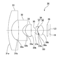
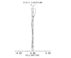
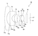
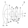
- FIG. 1 is a configuration diagram (ray diagram) of the imaging lens of the first embodiment.
- the imaging lens 10 of this example includes, in order from the object side to the image side, a first lens 11 having a negative power, a second lens 12 having a negative power, and a positive power. It consists of a third lens 13 and a fourth lens 14 with positive power.
- a diaphragm 15 is disposed between the third lens 13 and the fourth lens 14, and a plate glass 16 is disposed on the image side of the fourth lens 14.
- the imaging plane I1 is located away from the plate glass 16.
- the fourth lens 14 is a cemented lens including an object side lens 17 having negative power and an image side lens 18 having positive power.
- the object side lens 17 and the image side lens 18 are bonded by a resin adhesive, and a resin adhesive layer B ⁇ b> 1 is formed between the object side lens 17 and the image side lens 18.
- the first lens 11 is a meniscus lens in which the object side lens surface 11a protrudes toward the object side.
- the object side lens surface 11a and the image side lens surface 11b of the first lens 11 each have a positive curvature.
- the object side lens surface 12a has a negative curvature
- the image side lens surface 12b has a positive curvature. Accordingly, the object side lens surface 12a has a concave curved surface portion that is recessed toward the image side toward the optical axis L1
- the image side lens surface 12b is a concave surface that is recessed toward the object side toward the optical axis L1. It has a part.
- the object side lens surface 12a and the image side lens surface 12b are aspherical.
- the object side lens surface 13a has a positive curvature
- the image side lens surface 13b has a negative curvature. Therefore, the object side lens surface 13a includes a convex curved surface portion that protrudes toward the object side toward the optical axis L1, and the image side lens surface 13b protrudes toward the image side toward the optical axis L1. It has a part.
- the object side lens surface 13a and the image side lens surface 13b of the third lens 13 are aspherical.
- the object side lens 17 of the fourth lens 14 has an object side lens surface 17a having a positive curvature and an image side lens surface 17b having a positive curvature. Accordingly, the object side lens surface 17a includes a convex curved surface portion that protrudes toward the object side toward the optical axis L1, and the image side lens surface 17b is a concave surface that is recessed toward the object side toward the optical axis L1. It has a part.
- the object side lens surface 17a and the image side lens surface 17b of the object side lens 17 are aspherical.
- the image side lens 18 of the fourth lens 14 has an object side lens surface 18a having a positive curvature and an image side lens surface 18b having a negative curvature. Accordingly, the object side lens surface 18a includes a convex curved surface portion that protrudes toward the object side toward the optical axis L1, and the image side lens surface 18b protrudes toward the image axis toward the optical axis L1. It has a part.
- the object side lens surface 18a and the image side lens surface 18b of the image side lens 18 are aspherical.
- the image-side lens surface 17b of the object-side lens 17 and the object-side lens surface 18a of the image-side lens 18 which are the cemented surfaces of the object-side lens 17 and the image-side lens 18 have different aspherical shapes.
- the thickness of the resin adhesive layer B1 on the optical axis L1 is D
- the imaging lens 10 of this example has the following conditional expression (1 ) And conditional expression (2) are satisfied.
- the sag amount is the image side lens surface 17b of the object side lens 17 in the direction orthogonal to the optical axis L1 when a plane that includes the intersection of the lens surface and the optical axis L1 and is orthogonal to the optical axis L1 is used as a reference plane. Is the distance in the direction of the optical axis L1 from the reference surface to the lens surface at the height H at the effective diameter.
- S1 indicates a reference surface for the image side lens surface 17b of the object side lens 17
- S2 indicates a reference surface for the image side lens surface 18a of the image side lens 18.
- Conditional expression (1) and conditional expression (2) indicate that the resin adhesive layer between the image side lens surface 17b of the object side lens 17 and the object side lens surface 18a of the image side lens 18 which have different aspherical shapes.
- the thickness dimension of B1 that is, the distance between the image side lens surface 17b of the object side lens 17 and the object side lens surface 18a of the image side lens 18 which are the cemented surfaces of the two lenses constituting the cemented lens is defined. Is.
- the imaging lens 10 of this example satisfies the conditional expressions (1) and (2), the distance between the image side lens surface 17b of the object side lens 17 and the object side lens surface 18a of the image side lens 18 can be widened. it can. Accordingly, during the bonding operation of bonding the object side lens 17 and the image side lens 18, the image side lens surface 17b of the object side lens 17 and the object side lens surface 18a of the image side lens 18 are brought into contact with each other, and each lens surface is contacted. It is possible to prevent or suppress the occurrence of damage.
- the distance between the image-side lens surface 17b of the object-side lens 17 and the object-side lens surface 18a of the image-side lens 18 is wide, it is easy for the resin adhesive to go around between these lens surfaces. It is possible to prevent bubbles from remaining.
- the imaging lens 10 of this example satisfies the following conditional expression (3).
- D 100 ⁇ m (3)
- the imaging lens 10 of the present example satisfies the following conditional expression (4). 0.9 ⁇ Rs / f ⁇ 1.3 (4)
- the imaging lens 10 of this example has the following conditional expression (5) Meet. ⁇ 3.0 ⁇ (f41 / f42) /f ⁇ 1.5 (5)
- the Abbe number of the first lens 11, the second lens 12, and the image side lens 18 is 40 or more, and the Abbe number of the third lens 13 and the object side lens 17 is 31 or less.
- chromatic aberration is corrected.
- the F number of the imaging lens 10 of this example is set to Fno.
- the focal length of the entire lens system is f
- the focal length of the first lens 11 is f1
- the focal length of the second lens 12 is f2
- the focal length of the third lens 13 is f3
- the focal length of the fourth lens 14 is f4.
- Table 1A shows lens data of each lens surface of the imaging lens 10.
- each lens surface is specified in the order counted from the object side.
- the lens surface marked with an asterisk is aspheric.
- the 7th surface is the diaphragm 15, and the 12th and 13th surfaces are the object side glass surface and the image side glass surface of the plate glass 16.
- the unit of curvature radius and spacing is millimeters.
- the values of Nd (refractive index) and ⁇ d (Abbe number) of the 10 surfaces indicate the values of the resin adhesive layer B1.
- Table 1B shows aspherical coefficients for defining the aspherical shape of the aspherical lens surface. Also in Table 1B, each lens surface is specified in the order counted from the object side.
- the aspherical shape adopted for the lens surface is such that Y is the sag amount, c is the reciprocal of the radius of curvature, K is the cone coefficient, h is the ray height, 4th order, 6th order, 8th order, 10th order, 12th order,
- 14th and 16th order aspherical coefficients are A4, A6, A8, A10, A12, A14, and A16, respectively, they are expressed by the following equations.
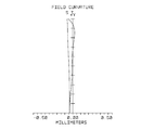
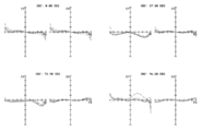
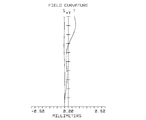
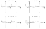
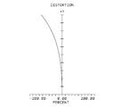
- (Function and effect) 3A to 3D are a longitudinal aberration diagram, a lateral aberration diagram, a field curvature diagram, and a distortion diagram of the imaging lens 10, respectively.
- the horizontal axis indicates the position where the light beam intersects the optical axis L1
- the vertical axis indicates the height at the pupil diameter.
- the horizontal axis indicates the entrance pupil coordinates
- the vertical axis indicates the amount of aberration.
- 3A and 3B show simulation results for a plurality of light beams having different wavelengths.
- the horizontal axis indicates the distance in the direction of the optical axis L1, and the vertical axis indicates the height of the image.
- S represents the field curvature aberration on the sagittal surface
- T represents the field curvature aberration on the tangential surface.
- the horizontal axis indicates the amount of image distortion
- the vertical axis indicates the height of the image.
- the imaging lens 10 of this example As shown in FIG. 3A, according to the imaging lens 10 of this example, the axial chromatic aberration is corrected well. In addition, as shown in FIG. 3B, color bleeding is suppressed. As shown in FIGS. 3A and 3B, both axial chromatic aberration and lateral chromatic aberration are corrected in a balanced manner in the peripheral portion. Furthermore, as shown in FIG. 3C, according to the imaging lens 10 of this example, the field curvature is corrected well. Therefore, the imaging lens 10 has a high resolution.
- the imaging lens 10 is designed such that the interval on the optical axis L1 between the image side lens surface 17b of the object side lens 17 and the object side lens surface 18a of the image side lens 18 is 20 ⁇ m or more in advance. Therefore, at the time of designing, it is possible to consider the shift to the plus side of the curvature of field on the tangential surface, which occurs when the resin adhesive layer B1 becomes thick. Therefore, according to the imaging lens 10 of the present example, as shown in FIG. 3C, the shift of the field curvature on the tangential surface to the plus side is suppressed.
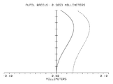
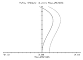
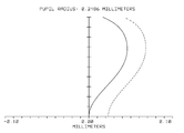
- FIG. 4 is a spherical aberration diagram of the imaging lens 10, and the solid line shows the spherical aberration with respect to a light beam having a wavelength of 588 nm (visible light beam).
- a dotted line indicates spherical aberration with respect to a light ray having a wavelength of 850 nm (near infrared ray).
- the horizontal axis of the spherical aberration diagram is the position where the light beam intersects the optical axis, and the vertical axis is the height at the pupil diameter. As shown in FIG.
- spherical aberration with respect to a light beam having a wavelength of 850 nm is corrected, and it is not necessary to perform focusing when photographing under visible light and when photographing under near infrared rays. That is, in the imaging lens 10 of the present example, it is possible to suppress occurrence of a focus shift between shooting using visible light and shooting using near infrared rays.
- the fourth lens 14 is composed of a single lens that is not a cemented lens, both spherical aberration for a light beam having a wavelength of 588 nm (visible light) and spherical aberration for a light beam having a wavelength of 850 nm (near infrared light) are balanced. It is difficult to correct well so that no out-of-focus occurs between photographing using visible light and photographing using near infrared rays.
- FIG. 5 is a configuration diagram (ray diagram) of the imaging lens of the second embodiment.
- the imaging lens 20 of this example includes, in order from the object side to the image side, a first lens 21 having a negative power, a second lens 22 having a negative power, and a positive power. It consists of a third lens 23 and a fourth lens 24 with positive power.
- a diaphragm 25 is disposed between the third lens 23 and the fourth lens 24, and a plate glass 26 is disposed on the image side of the fourth lens 24.
- the image plane I2 is located away from the plate glass 26.
- the fourth lens 24 is a cemented lens including an object side lens 27 having negative power and an image side lens 28 having positive power.
- the object side lens 27 and the image side lens 28 are bonded by a resin adhesive, and a resin adhesive layer B ⁇ b> 2 is formed between the object side lens 27 and the image side lens 28. Since the shape of each lens constituting the imaging lens 20 of this example is the same as the shape of each corresponding lens of the imaging lens 10 of Example 1, the description thereof is omitted.
- the F number of the imaging lens 20 of this example is set to Fno.
- the focal length of the entire lens system is f
- the focal length of the first lens 21 is f1
- the focal length of the second lens 22 is f2
- the focal length of the third lens 23 is f3
- the focal length of the fourth lens 24 is f4.
- the thickness dimension of the resin adhesive layer B2 on the optical axis L2 is D
- the sag amount of the image side lens surface 27b of the object side lens 27 at the height H is Sg1H
- the sag amount of the object side lens surface 28a of the image side lens 28 at the height H is Sg2H
- the image side lens surface 27b of the object side lens 27 is Sg1H
- the sag amount of the object side lens surface 28a of the image side lens 28 at the height H is Sg2H
- the image side lens surface 27b of the object side lens 27 is Sg1H
- Rs is the radius of curvature
- R31 is the radius of curvature of the object side lens surface 23a of the third lens 23
- R32 is the radius of curvature of the image side lens surface 23b of the third lens 23.
- the Abbe number of the first lens 21, the second lens 22, and the image side lens 28 is 40 or more, and the Abbe number of the third lens 23 and the object side lens 27 is 31 or less.
- chromatic aberration is corrected.
- Table 2A shows lens data of each lens surface of the imaging lens 20.
- each lens surface is specified in the order counted from the object side.
- the lens surface marked with an asterisk is aspheric.
- the 7th surface is the aperture 25, and the 12th and 13th surfaces are the object side glass surface and the image side glass surface of the plate glass 26.
- the unit of curvature radius and spacing is millimeters.
- the value of Nd (refractive index) and ⁇ d (Abbe number) of the tenth surface indicates the value of the resin adhesive layer B2.
- Table 2B shows aspherical coefficients for defining the aspherical shape of the aspherical lens surface. Also in Table 2B, each lens surface is specified in the order counted from the object side.
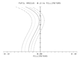
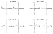
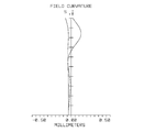
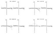
- (Function and effect) 6A to 6D are a longitudinal aberration diagram, a lateral aberration diagram, a field curvature diagram, and a distortion diagram of the imaging lens 20, respectively.
- the axial chromatic aberration is well corrected.
- color bleeding is suppressed.
- both axial chromatic aberration and lateral chromatic aberration are corrected in a balanced manner in the peripheral portion.
- the curvature of field is corrected well. Therefore, the imaging lens 20 has a high resolution.
- the imaging lens 20 is designed such that the distance between the image side lens surface 27b of the object side lens 27 and the object side lens surface 28a of the image side lens 28 on the optical axis L2 is 20 ⁇ m or more in advance. Therefore, at the time of designing, it is possible to consider the shift to the plus side of the curvature of field on the tangential surface that occurs due to the thick resin adhesive layer B2. Therefore, according to the imaging lens 20 of the present example, as shown in FIG. 6C, the shift of the field curvature on the tangential surface to the plus side is suppressed.
- FIG. 7 is a spherical aberration diagram of the imaging lens 20, and the solid line shows the spherical aberration with respect to a light beam having a wavelength of 588 nm (visible light beam).
- a dotted line indicates spherical aberration with respect to a light ray having a wavelength of 850 nm (near infrared ray).
- the horizontal axis is the position where the light beam intersects the optical axis, and the vertical axis is the height at which the light beam enters the optical system. As shown in FIG.
- spherical aberration with respect to a light beam having a wavelength of 850 nm is corrected, so that it is not necessary to perform focusing when photographing under visible light and when photographing under near infrared rays.
- the imaging lens 20 of this example that is, in the imaging lens 20 of this example, occurrence of a focus shift between shooting using visible light and shooting using near infrared rays is suppressed.
- FIG. 8 is a configuration diagram (ray diagram) of the imaging lens of the third embodiment.
- the imaging lens 30 of this example includes, in order from the object side to the image side, a first lens 31 having a negative power, a second lens 32 having a negative power, and a positive power. It consists of a third lens 33 and a fourth lens 34 having positive power. A diaphragm 35 is disposed between the third lens 33 and the fourth lens 34, and a plate glass 36 is disposed on the image side of the fourth lens 34.
- the imaging plane I3 is located away from the plate glass 36.
- the fourth lens 34 is a cemented lens including an object side lens 37 having negative power and an image side lens 38 having positive power.
- the object side lens 37 and the image side lens 38 are bonded by a resin adhesive, and a resin adhesive layer B ⁇ b> 3 is formed between the object side lens 37 and the image side lens 38. Since the shape of each lens constituting the imaging lens 30 of this example is the same as the shape of each corresponding lens of the imaging lens 10 of Example 1, the description thereof is omitted.
- the F number of the imaging lens 30 of this example is set to Fno.
- the focal length of the entire lens system is f
- the focal length of the first lens 31 is f1
- the focal length of the second lens 32 is f2
- the focal length of the third lens 33 is f3
- the focal length of the fourth lens 34 is f4.
- the thickness dimension of the resin adhesive layer B3 on the optical axis L3 is D
- the sag amount of the image side lens surface 37b of the object side lens 37 at the height H is Sg1H
- the sag amount of the object side lens surface 38a of the image side lens 38 at the height H is Sg2H
- the image side lens surface 37b of the object side lens 37 is Sg1H
- Rs is the radius of curvature
- R31 is the radius of curvature of the object side lens surface 33a of the third lens 33
- R32 is the radius of curvature of the image side lens surface 33b of the third lens 33.
- the Abbe number of the first lens 31, the second lens 32, and the image side lens 38 is 40 or more, and the Abbe number of the third lens 33 and the object side lens 37 is 31 or less.
- chromatic aberration is corrected.
- Table 3A shows lens data of each lens surface of the imaging lens 30.
- each lens surface is specified in the order counted from the object side.
- the lens surface marked with an asterisk is aspheric.
- Surface 7 is a diaphragm 35
- surfaces 12 and 13 are an object-side glass surface and an image-side glass surface of the plate glass 36.
- the unit of curvature radius and spacing is millimeters. Note that the values of Nd (refractive index) and ⁇ d (Abbe number) of the tenth surface indicate the values of the resin adhesive layer B3.
- Table 3B shows aspherical coefficients for defining the aspherical shape of the aspherical lens surface. Also in Table 3B, each lens surface is specified in the order counted from the object side.
- FIG. 9A to 9D are a longitudinal aberration diagram, a lateral aberration diagram, a field curvature diagram, and a distortion diagram of the imaging lens 30.
- FIG. 9A according to the imaging lens 30 of the present example, the axial chromatic aberration is corrected well. Further, as shown in FIG. 9B, color bleeding is suppressed. Further, as shown in FIGS. 9A and 9B, both axial chromatic aberration and lateral chromatic aberration are corrected in a balanced manner in the peripheral portion. Furthermore, as shown in FIG. 9C, according to the imaging lens 30 of this example, the curvature of field is well corrected. Therefore, the imaging lens 30 has a high resolution.
- the imaging lens 30 is designed such that the distance on the optical axis L3 between the image side lens surface 37b of the object side lens 37 and the object side lens surface 38a of the image side lens 38 is 20 ⁇ m or more in advance. Therefore, at the time of designing, it is possible to consider the shift to the plus side of the curvature of field on the tangential surface, which occurs when the resin adhesive layer B3 becomes thick. Therefore, according to the imaging lens 30 of the present example, as shown in FIG. 9C, the shift of the field curvature on the tangential surface to the plus side is suppressed.
- FIG. 10 is a spherical aberration diagram of the imaging lens 30, and the solid line shows the spherical aberration with respect to a light beam having a wavelength of 588 nm (visible light beam).
- a dotted line indicates spherical aberration with respect to a light ray having a wavelength of 850 nm (near infrared ray).
- the horizontal axis is the position where the light beam intersects the optical axis, and the vertical axis is the height at which the light beam enters the optical system. As shown in FIG.
- spherical aberration with respect to a light beam having a wavelength of 850 nm is corrected, so that it is not necessary to perform focusing when photographing under visible light and when photographing under near infrared rays. That is, in the imaging lens 30 of the present example, it is possible to suppress the occurrence of a focus shift between shooting using visible light and shooting using near infrared rays.
- FIG. 11 is a configuration diagram (ray diagram) of the imaging lens of Example 4.
- the imaging lens 40 of this example includes, in order from the object side to the image side, a first lens 41 having a negative power, a second lens 42 having a negative power, and a positive power. It consists of a third lens 43 and a fourth lens 44 with positive power.
- a diaphragm 45 is disposed between the third lens 43 and the fourth lens 44, and a plate glass 46 is disposed on the image side of the fourth lens 44.
- the imaging plane I4 is located away from the plate glass 46.
- the fourth lens 44 is a cemented lens including an object side lens 47 having negative power and an image side lens 48 having positive power.
- the object side lens 47 and the image side lens 48 are bonded by a resin adhesive, and a resin adhesive layer B 4 is formed between the object side lens 47 and the image side lens 48. Since the shape of each lens constituting the imaging lens 40 of this example is the same as the shape of each corresponding lens of the imaging lens 10 of Example 1, the description thereof is omitted.
- the F number of the imaging lens 40 of this example is set to Fno.
- the focal length of the entire lens system is f
- the focal length of the first lens 41 is f1
- the focal length of the second lens 42 is f2
- the focal length of the third lens 43 is f3
- the focal length of the fourth lens 44 is f4.
- the thickness dimension of the resin adhesive layer B4 on the optical axis L4 is D
- the sag amount of the image side lens surface 47b of the object side lens 47 at the height H is Sg1H
- the sag amount of the object side lens surface 48a of the image side lens 48 at the height H is Sg2H
- the image side lens surface 47b of the object side lens 47 is Sg1H
- Rs is the radius of curvature
- R31 is the radius of curvature of the object side lens surface 43a of the third lens 43
- R32 is the radius of curvature of the image side lens surface 43b of the third lens 43.
- the Abbe number of the first lens 41, the second lens 42, and the image side lens 48 is 40 or more, and the Abbe number of the third lens 43 and the object side lens 47 is 31 or less.
- chromatic aberration is corrected.
- Table 4A shows lens data of each lens surface of the imaging lens 40.
- each lens surface is specified in the order counted from the object side.
- the lens surface marked with an asterisk is aspheric.
- the 7th surface is an aperture 45
- the 12th and 13th surfaces are an object side glass surface and an image side glass surface of the plate glass 46.
- the unit of curvature radius and spacing is millimeters.
- the value of Nd (refractive index) and ⁇ d (Abbe number) of the tenth surface indicates the value of the resin adhesive layer B4.
- Table 4B shows aspherical coefficients for defining the aspherical shape of the aspherical lens surface. Also in Table 4B, each lens surface is specified in the order counted from the object side.
- FIG. 12A to 12D are a longitudinal aberration diagram, a lateral aberration diagram, a field curvature diagram, and a distortion diagram of the imaging lens 40.
- FIG. 12A according to the imaging lens 40 of this example, the axial chromatic aberration is well corrected.
- FIG. 12B color bleeding is suppressed.
- FIGS. 12A and 12B both axial chromatic aberration and lateral chromatic aberration are corrected in a balanced manner in the peripheral portion.
- FIG. 12C according to the imaging lens 40 of this example, the curvature of field is well corrected. Therefore, the imaging lens 40 has a high resolution.
- the imaging lens 40 is designed such that the interval on the optical axis L4 between the image side lens surface 47b of the object side lens 47 and the object side lens surface 48a of the image side lens 48 is 20 ⁇ m or more in advance. Accordingly, at the time of designing, it is possible to consider the shift to the plus side of the curvature of field on the tangential surface that occurs due to the thick resin adhesive layer B4. Therefore, according to the imaging lens 40 of the present example, as shown in FIG. 12C, the shift of the field curvature on the tangential surface to the plus side is suppressed.
- FIG. 13 is a spherical aberration diagram of the imaging lens 40, and the solid line shows the spherical aberration with respect to light rays having a wavelength of 588 nm (visible rays).
- a dotted line indicates spherical aberration with respect to a light ray having a wavelength of 850 nm (near infrared ray).
- the horizontal axis is the position where the light beam intersects the optical axis, and the vertical axis is the height at which the light beam enters the optical system. As shown in FIG.
- the imaging lens 40 in the imaging lens 40, spherical aberration with respect to a light beam having a wavelength of 850 nm is corrected, and it is not necessary to perform focusing when photographing under visible light and when photographing under near infrared rays. That is, in the imaging lens 40 of the present example, it is possible to suppress the occurrence of a focus shift between shooting using visible light and shooting using near infrared rays.
- FIG. 14 is a configuration diagram (ray diagram) of the imaging lens of Example 5.
- the imaging lens 50 of this example includes, in order from the object side to the image side, a first lens 51 having a negative power, a second lens 52 having a negative power, and a positive power. It consists of a third lens 53 and a fourth lens 54 having positive power. A diaphragm 55 is disposed between the third lens 53 and the fourth lens 54, and a plate glass 56 is disposed on the image side of the fourth lens 54.
- the imaging plane I5 is located away from the plate glass 56.
- the fourth lens 54 is a cemented lens including an object side lens 57 having negative power and an image side lens 58 having positive power.
- the object side lens 57 and the image side lens 58 are bonded by a resin adhesive, and a resin adhesive layer B ⁇ b> 5 is formed between the object side lens 57 and the image side lens 58.
- the shape of each lens composing the imaging lens 50 of this example is the same as the shape of each corresponding lens of the imaging lens 10 of Example 1, and therefore the description thereof is omitted.
- the F number of the imaging lens 50 of this example is set to Fno.
- the focal length of the entire lens system is f
- the focal length of the first lens 51 is f1
- the focal length of the second lens 52 is f2
- the focal length of the third lens 53 is f3
- the focal length of the fourth lens 54 is f4.
- the thickness dimension of the resin adhesive layer B5 on the optical axis L5 is D
- the sag amount of the image side lens surface 57b of the object side lens 57 at the height H is Sg1H
- the sag amount of the object side lens surface 58a of the image side lens 58 at the height H is Sg2H
- the image side lens surface 57b of the object side lens 57 is Sg1H
- the sag amount of the object side lens surface 58a of the image side lens 58 at the height H is Sg2H
- the image side lens surface 57b of the object side lens 57 is Sg1H
- the radius of curvature of the third lens 53 is Rs
- the radius of curvature of the object-side lens surface 53a of the third lens 53 is R31
- the radius of curvature of the image-side lens surface 53b of the third lens 53 is R32.
- the Abbe number of the first lens 51, the second lens 52, and the image side lens 58 is 40 or more, and the Abbe number of the third lens 53 and the object side lens 57 is 31 or less.
- chromatic aberration is corrected.
- Table 5A shows lens data of each lens surface of the imaging lens 50.
- each lens surface is specified in the order counted from the object side.
- the lens surface marked with an asterisk is aspheric.
- Surface 7 is a diaphragm 55
- surfaces 12 and 13 are an object side glass surface and an image side glass surface of the plate glass 56.
- the unit of curvature radius and spacing is millimeters.
- the value of Nd (refractive index) and ⁇ d (Abbe number) of the tenth surface indicates the value of the resin adhesive layer B5.
- Table 5B shows aspherical coefficients for defining the aspherical shape of the aspherical lens surface. Also in Table 5B, each lens surface is specified in the order counted from the object side.
- FIG. 15A to 15D are a longitudinal aberration diagram, a lateral aberration diagram, a field curvature diagram, and a distortion diagram of the imaging lens 50.
- FIG. 15A according to the imaging lens 50 of the present example, the axial chromatic aberration is well corrected.
- FIG. 15B color bleeding is suppressed.
- FIGS. 15A and 15B both axial chromatic aberration and lateral chromatic aberration are corrected in a balanced manner in the peripheral portion.
- FIG. 15C according to the imaging lens 50 of this example, the curvature of field is favorably corrected. Therefore, the imaging lens 50 has a high resolution.
- the imaging lens 50 is designed with an interval on the optical axis L5 between the image side lens surface 57b of the object side lens 57 and the object side lens surface 58a of the image side lens 58 set to 20 ⁇ m or more in advance. Accordingly, at the time of designing, it is possible to consider the shift to the plus side of the curvature of field on the tangential surface, which occurs when the resin adhesive layer B5 becomes thick. Therefore, according to the imaging lens 50 of the present example, as shown in FIG. 15C, the shift of the field curvature on the tangential surface to the plus side is suppressed.
- FIG. 16 is a spherical aberration diagram of the imaging lens 50, and the solid line shows the spherical aberration with respect to a light beam having a wavelength of 588 nm (visible light beam).
- a dotted line indicates spherical aberration with respect to a light ray having a wavelength of 850 nm (near infrared ray).
- the horizontal axis is the position where the light beam intersects the optical axis, and the vertical axis is the height at which the light beam enters the optical system. As shown in FIG.
- the imaging lens 50 in the imaging lens 50, spherical aberration with respect to a light beam having a wavelength of 850 nm is corrected, and it is not necessary to perform focusing when photographing under visible light and when photographing under near infrared rays. That is, in the imaging lens 50 of the present example, it is possible to suppress the occurrence of a focus shift between shooting using visible light and shooting using near infrared rays.
- the image side lens surfaces (13b, 23b, 33b, 43b, 53b) of the third lens have a negative curvature, and are convex curved surfaces protruding toward the image side toward the optical axis.
- This image side lens surface (13b, 23b, 33b, 43b, 53b) has a positive curvature and a concave curved surface portion that is recessed toward the object side toward the optical axis. Also good. Also in this case, satisfying conditional expression (6) makes it easy to make the imaging lenses 10 to 50 wide-angle lenses.
- FIG. 17 is an explanatory diagram of an imaging apparatus equipped with the imaging lens of the present invention.
- the imaging device 60 includes an imaging device 61 in which a sensor surface 61 a is arranged on the imaging plane I1 (focal position) of the imaging lens 10.
- the image sensor 61 is a CCD sensor or a CMOS sensor.
- the imaging device 60 can have a high resolution by adopting an imaging device having a large number of pixels as the imaging device 61.
- the imaging device 60 can be equipped with the imaging lenses 20 to 50 in the same manner as the imaging lens 10, and in this case, the same effect can be obtained.
- the imaging device 60 As indicated by a two-dot chain line in FIG. 17, in the imaging device 60, near-infrared rays and visible rays in a band including a wavelength of 850 nm are transmitted between the imaging lens 10 and the imaging element 61 and guided to the imaging lens 10.
- the optical filter 62 By disposing the optical filter 62, it is possible to obtain an imaging device that uses near infrared rays and visible rays.
- the imaging lens 10 prevents or suppresses the occurrence of a focus shift between shooting using visible light and shooting using near infrared rays.
- the optical filter 62 only by mounting the optical filter 62 on the imaging device 60, imaging using near infrared rays including a wavelength of 850 nm, for example, light in a band of 800 nm to 1100 nm, and visible light, that is, light having a wavelength of 400 nm to 700 nm. It is possible to configure an image pickup apparatus that performs both shootings using the. Also, in the imaging lenses 20 to 50, occurrence of focus shift between shooting using visible light and shooting using near infrared rays is prevented or suppressed.
- an imaging device that performs both imaging using near infrared rays including a wavelength of 850 nm and imaging using visible light only by mounting the optical filter 62 on the imaging device 60 is configured.
- the optical filter 62 may be disposed on the object side of the imaging lenses 10 to 50.
- Reference Example 1 The imaging lenses of Reference Examples 1 to 3 will be described below with reference to FIGS.
- the imaging lenses of Reference Examples 1 to 3 have the same configuration as that of Examples 1 to 5, but the thickness on the optical axis of the resin adhesive layer bonding the two lenses constituting the cemented lens.
- the dimension, that is, the distance on the optical axis between the two lenses constituting the cemented lens is less than 20 ⁇ m.
- FIG. 18 is a configuration diagram (ray diagram) of the imaging lens of Reference Example 1.
- the imaging lens 70 of this example includes, in order from the object side to the image side, a first lens 71 having negative power, a second lens 72 having negative power, and positive power. It consists of a third lens 73 and a fourth lens 74 having positive power.
- a diaphragm 75 is disposed between the third lens 73 and the fourth lens 74, and a plate glass 76 is disposed on the image side of the fourth lens 74.
- the image plane I7 is located away from the plate glass 76.
- the fourth lens 74 is a cemented lens including an object side lens 77 having negative power and an image side lens 78 having positive power.
- the image side lens surface 77b of the object side lens 77 and the object side lens surface 78a of the image side lens 78 which are the cemented surfaces of the cemented lens, have the same shape.
- the object side lens 77 and the image side lens 78 are bonded by a resin adhesive, but the gap between the object side lens 77 and the image side lens 78 is practically zero.
- the F number of the imaging lens 70 of this example is set to Fno.
- the focal length of the entire lens system is f
- the focal length of the first lens 71 is f1
- the focal length of the second lens 72 is f2
- the focal length of the third lens 73 is f3
- the focal length of the fourth lens 74 is f4.
- the imaging lens 70 of the present example has a sag amount of the image side lens surface 77b of the object side lens 77 at a height H at an effective diameter of the image side lens surface 77b of the object side lens 77 in a direction orthogonal to the optical axis L7.
- the Abbe number of the first lens 71, the second lens 72, and the image side lens 78 is 40 or more, and the Abbe number of the third lens 73 and the object side lens 77 is 31 or less.
- chromatic aberration is corrected.
- Table 6A shows lens data of each lens surface of the imaging lens 70.
- each lens surface is specified in the order counted from the object side.
- the lens surface marked with an asterisk is aspheric.
- Surface 7 is a diaphragm 75, and surfaces 11 and 12 are an object side glass surface and an image side glass surface of the plate glass 76.
- the unit of curvature radius and spacing is millimeters.
- Table 6B shows aspherical coefficients for defining the aspherical shape of the aspherical lens surface. Also in Table 6B, each lens surface is specified in the order counted from the object side.
- 19A to 19D are a longitudinal aberration diagram, a lateral aberration diagram, a field curvature diagram, and a distortion diagram of the imaging lens 70, respectively.
- the axial chromatic aberration is corrected well.
- color bleeding is suppressed.
- both axial chromatic aberration and lateral chromatic aberration are corrected in a balanced manner in the peripheral portion.
- the field curvature is corrected well.
- FIG. 20 is a configuration diagram (ray diagram) of the imaging lens of Reference Example 2.
- the imaging lens 80 of this example includes, in order from the object side to the image side, a first lens 81 having negative power, a second lens 82 having negative power, and positive power. It consists of a third lens 83 and a fourth lens 84 having positive power.
- a diaphragm 85 is disposed between the third lens 83 and the fourth lens 84, and a plate glass 86 is disposed on the image side of the fourth lens 84.
- the image plane I8 is located away from the plate glass 86.
- the fourth lens 84 is a cemented lens including an object side lens 87 having negative power and an image side lens 88 having positive power.
- the image side lens surface 87b of the object side lens 87 and the object side lens surface 88a of the image side lens 88 which are the cemented surfaces of the cemented lens, have the same shape.
- the object side lens 87 and the image side lens 88 are bonded by a resin adhesive, but the gap between the object side lens 87 and the image side lens 88 is practically zero.
- the F number of the imaging lens 80 of this example is set to Fno.
- the focal length of the entire lens system is f
- the focal length of the first lens 81 is f1
- the focal length of the second lens 82 is f2
- the focal length of the third lens 83 is f3
- the focal length of the fourth lens 84 is f4.
- mm f2 ⁇ 2.080mm
- the Abbe number of the first lens 81, the second lens 82, and the image side lens 88 is 40 or more, and the Abbe number of the third lens 83 and the object side lens 87 is 31 or less.
- chromatic aberration is corrected.
- Table 7A shows lens data of each lens surface of the imaging lens 80.
- each lens surface is specified in the order counted from the object side.
- the lens surface marked with an asterisk is aspheric.
- the 7th surface is a diaphragm 85, and the 11th and 12th surfaces are an object side glass surface and an image side glass surface of the plate glass 86.
- the unit of curvature radius and spacing is millimeters.
- Table 7B shows aspherical coefficients for defining the aspherical shape of the aspherical lens surface. Also in Table 7B, each lens surface is specified in the order counted from the object side.
- FIG. 21A to 21D are a longitudinal aberration diagram, a lateral aberration diagram, a field curvature diagram, and a distortion diagram of the imaging lens 80.
- FIG. 21A according to the imaging lens 80 of the present example, the axial chromatic aberration is well corrected.
- FIG. 21B color bleeding is suppressed.
- FIGS. 21A and 21B both axial chromatic aberration and lateral chromatic aberration are corrected in a balanced manner in the peripheral portion.
- FIG. 21C according to the imaging lens 80 of the present example, the curvature of field is well corrected.
- FIG. 22 is a configuration diagram (ray diagram) of the imaging lens of Reference Example 3.
- the imaging lens 90 of this example includes, in order from the object side to the image side, a first lens 91 having negative power, a second lens 92 having negative power, and positive power. It consists of a third lens 93 and a fourth lens 94 having positive power.
- a diaphragm 95 is disposed between the third lens 93 and the fourth lens 94, and a plate glass 96 is disposed on the image side of the fourth lens 94.
- the imaging plane I9 is located away from the plate glass 96.
- the fourth lens 94 is a cemented lens including an object side lens 97 having negative power and an image side lens 98 having positive power.
- the image side lens surface 97b of the object side lens 97 and the object side lens surface 98a of the image side lens 98, which are the cemented surfaces of the cemented lens, have the same shape.
- the object side lens 97 and the image side lens 98 are bonded by a resin adhesive, but the gap between the object side lens 97 and the image side lens 98 is practically zero.
- the F number of the imaging lens 90 of this example is set to Fno.
- the focal length of the entire lens system is f
- the focal length of the first lens 91 is f1
- the focal length of the second lens 92 is f2
- the focal length of the third lens 93 is f3
- the focal length of the fourth lens 94 is f4.
- the imaging lens 90 of the present example has a sag amount of the image side lens surface 97b of the object side lens 97 at the height H at the effective diameter of the image side lens surface 97b of the object side lens 97 in the direction orthogonal to the optical axis L9.
- conditional expressions (2) and (4) to (6) shown in the description of the first embodiment are satisfied. .
- the values of conditional expressions (4) to (6) are as follows.
- the Abbe number of the first lens 91, the second lens 92, and the image side lens 98 is 40 or more, and the Abbe number of the third lens 93 and the object side lens 97 is 31 or less.
- chromatic aberration is corrected.
- Table 8A shows lens data of each lens surface of the imaging lens 90.
- each lens surface is specified in the order counted from the object side.
- the lens surface marked with an asterisk is aspheric.
- Surface 7 is a diaphragm 95
- surfaces 11 and 12 are an object side glass surface and an image side glass surface of the plate glass 96.
- the unit of curvature radius and spacing is millimeters.
- Table 8B shows aspheric coefficients for defining the aspherical shape of the aspherical lens surface. Also in Table 8B, each lens surface is specified in the order counted from the object side.
- 23A to 23D are a longitudinal aberration diagram, a lateral aberration diagram, a field curvature diagram, and a distortion diagram of the imaging lens 90, respectively.
- the axial chromatic aberration is well corrected.
- color bleeding is suppressed.
- both axial chromatic aberration and lateral chromatic aberration are corrected in a balanced manner in the peripheral portion.
- the curvature of field is well corrected.
Abstract
Description
物体側から像側に向かって順に、負のパワーを備える第1レンズ、負のパワーを備える第2レンズ、正のパワーを備える第3レンズ、および、正のパワーを備える第4レンズからなり、
前記第4レンズは、負のパワーを備える物体側レンズと正のパワーを備える像側レンズからなる接合レンズであり、前記物体側レンズと前記像側レンズとを接着している樹脂接着剤層を備え、
前記物体側レンズの像側レンズ面および前記像側レンズの物体側レンズ面は、それぞれが互いに異なる非球面形状をしており、
光軸上における前記接着剤樹脂層の厚さ寸法をD、前記光軸と直交する方向の前記物体側レンズの像側レンズ面の有効径での高さHにおけるサグ量をSg1H、前記高さHにおける前記像側レンズの物体側レンズ面のサグ量をSg2Hとしたときに、以下の条件式(1)および条件式(2)を満たすことを特徴とする。
20μm ≦ D (1)
Sg1H ≦ Sg2H (2)
D ≦ 100μm (3)
0.9 ≦ Rs/f ≦ 1.3 (4)
-3.0 ≦(f41/f42)/f ≦ -1.5 (5)
R31 ≦ |R32| (6)
図1は実施例1の撮像レンズの構成図(光線図)である。図1に示すように、本例の撮像レンズ10は、物体側から像側に向かって順に、負のパワーを備える第1レンズ11、負のパワーを備える第2レンズ12、正のパワーを備える第3レンズ13、および、正のパワーを備える第4レンズ14からなる。第3レンズ13と第4レンズ14の間には絞り15が配置されており、第4レンズ14の像側には板ガラス16が配置されている。結像面I1は板ガラス16から離れた位置にある。第4レンズ14は、負のパワーを備える物体側レンズ17と正のパワーを備える像側レンズ18からなる接合レンズである。物体側レンズ17と像側レンズ18とは樹脂接着剤により接着されており、物体側レンズ17と像側レンズ18の間には樹脂接着剤層B1が形成されている。
20μm ≦ D (1)
Sg1H ≦ Sg2H (2)
D ≦ 100μm (3)
0.9 ≦ Rs/f ≦ 1.3 (4)
-3.0 ≦(f41/f42)/f ≦ -1.5 (5)
R31 ≦ |R32| (6)
Fno.=2.0
ω=99.4°
L=16.089mm
f=1.155mm
f1=-8.193mm
f2=-2.685mm
f3=4.126mm
f4=3.275mm
f41=-3.351mm
f42=1.885mm


図3A~図3Dは撮像レンズ10の縦収差図、横収差図、像面湾曲図、歪曲収差図である。図3Aの縦収差図では横軸は光線が光軸L1と交わる位置を示し、縦軸は瞳径での高さを示す。図3Bの横収差図では横軸は入射瞳座標を示し、縦軸は収差量を示す。図3A、図3Bでは、波長の異なる複数の光線についてのシミュレーション結果を示してある。図3Cの像面湾曲図では横軸は光軸L1方向の距離を示し、縦軸は像の高さを示す。図3Cにおいて、Sはサジタル面における像面湾曲収差を示し、Tはタンジェンシャル面における像面湾曲収差を示す。図3Dの歪曲収差図では横軸は像の歪み量を示し、縦軸は像の高さを示す。
図5は実施例2の撮像レンズの構成図(光線図)である。図5に示すように、本例の撮像レンズ20は、物体側から像側に向かって順に、負のパワーを備える第1レンズ21、負のパワーを備える第2レンズ22、正のパワーを備える第3レンズ23、および、正のパワーを備える第4レンズ24からなる。第3レンズ23と第4レンズ24の間には絞り25が配置されており、第4レンズ24の像側には板ガラス26が配置されている。結像面I2は板ガラス26から離れた位置にある。第4レンズ24は、負のパワーを備える物体側レンズ27と正のパワーを備える像側レンズ28からなる接合レンズである。物体側レンズ27と像側レンズ28とは樹脂接着剤により接着されており、物体側レンズ27と像側レンズ28の間には樹脂接着剤層B2が形成されている。本例の撮像レンズ20を構成する各レンズの形状は、実施例1の撮像レンズ10の対応する各レンズの形状と同様なので、その説明を省略する。
Fno.=2.0
ω=97.6°
L=15.598mm
f=1.141mm
f1=-8.378mm
f2=-2.600mm
f3=4.060mm
f4=3.199mm
f41=-3.520mm
f42=1.829mm
20μm ≦ D=20μm (1)
Sg1H ≦ Sg2H (2)
D=20μm ≦ 100μm (3)
0.9 ≦ Rs/f=1.112 ≦ 1.3 (4)
-3.0 ≦(f41/f42)/f=-1.69 ≦ -1.5 (5)
R31=3.428 ≦ |R32|=|-5.958| (6)


図6A~図6Dは撮像レンズ20の縦収差図、横収差図、像面湾曲図、歪曲収差図である。図6Aに示すように、本例の撮像レンズ20によれば、軸上の色収差が良好に補正されている。また、図6Bに示すように、色の滲みが抑制されている。また、図6A、図6Bに示すように、軸上の色収差と倍率色収差の双方が周辺部分においてもバランス良く補正されている。さらに、図6Cに示すように、本例の撮像レンズ20によれば、像面湾曲が良好に補正されている。従って、撮像レンズ20が高解像度となる。
図8は実施例3の撮像レンズの構成図(光線図)である。図8に示すように、本例の撮像レンズ30は、物体側から像側に向かって順に、負のパワーを備える第1レンズ31、負のパワーを備える第2レンズ32、正のパワーを備える第3レンズ33、および、正のパワーを備える第4レンズ34からなる。第3レンズ33と第4レンズ34の間には絞り35が配置されており、第4レンズ34の像側には板ガラス36が配置されている。結像面I3は板ガラス36から離れた位置にある。第4レンズ34は、負のパワーを備える物体側レンズ37と正のパワーを備える像側レンズ38からなる接合レンズである。物体側レンズ37と像側レンズ38とは樹脂接着剤により接着されており、物体側レンズ37と像側レンズ38の間には樹脂接着剤層B3が形成されている。本例の撮像レンズ30を構成する各レンズの形状は、実施例1の撮像レンズ10の対応する各レンズの形状と同様なので、その説明を省略する。
Fno.=2.0
ω=96.0°
L=12.637mm
f=0.847mm
f1=-5.553mm
f2=-1.712mm
f3=2.742mm
f4=2.317mm
f41=-2.670mm
f42=1.493mm
20μm ≦ D=20μm (1)
Sg1H ≦ Sg2H (2)
D=20μm ≦ 100μm (3)
0.9 ≦ Rs/f=1.103 ≦ 1.3 (4)
-3.0 ≦(f41/f42)/f=-2.11 ≦ -1.5 (5)
R31=1.824 ≦ |R32|=|-8.292| (6)


図9A~図9Dは撮像レンズ30の縦収差図、横収差図、像面湾曲図、歪曲収差図である。図9Aに示すように、本例の撮像レンズ30によれば、軸上の色収差が良好に補正されている。また、図9Bに示すように、色の滲みが抑制されている。また、図9A、図9Bに示すように、軸上の色収差と倍率色収差の双方が周辺部分においてもバランス良く補正されている。さらに、図9Cに示すように、本例の撮像レンズ30によれば、像面湾曲が良好に補正されている。従って、撮像レンズ30が高解像度となる。
図11は実施例4の撮像レンズの構成図(光線図)である。図11に示すように、本例の撮像レンズ40は、物体側から像側に向かって順に、負のパワーを備える第1レンズ41、負のパワーを備える第2レンズ42、正のパワーを備える第3レンズ43、および、正のパワーを備える第4レンズ44からなる。第3レンズ43と第4レンズ44の間には絞り45が配置されており、第4レンズ44の像側には板ガラス46が配置されている。結像面I4は板ガラス46から離れた位置にある。第4レンズ44は、負のパワーを備える物体側レンズ47と正のパワーを備える像側レンズ48からなる接合レンズである。物体側レンズ47と像側レンズ48とは樹脂接着剤により接着されており、物体側レンズ47と像側レンズ48の間には樹脂接着剤層B4が形成されている。本例の撮像レンズ40を構成する各レンズの形状は、実施例1の撮像レンズ10の対応する各レンズの形状と同様なので、その説明を省略する。
Fno.=2.0
ω=96.0°
L=13.514mm
f=0.994mm
f1=-8.279mm
f2=-1.785mm
f3=2.929mm
f4=2.394mm
f41=-3.114mm
f42=1.479mm
20μm ≦ D=20μm (1)
Sg1H ≦ Sg2H (2)
D=20μm ≦ 100μm (3)
0.9 ≦ Rs/f=1.189 ≦ 1.3 (4)
-3.0 ≦(f41/f42)/f=-2.12 ≦ -1.5 (5)
R31=2.115 ≦ |R32|=|-5.863| (6)


図12A~図12Dは撮像レンズ40の縦収差図、横収差図、像面湾曲図、歪曲収差図である。図12Aに示すように、本例の撮像レンズ40によれば、軸上の色収差が良好に補正されている。また、図12Bに示すように、色の滲みが抑制されている。また、図12A、図12Bに示すように、軸上の色収差と倍率色収差の双方が周辺部分においてもバランス良く補正されている。さらに、図12Cに示すように、本例の撮像レンズ40によれば、像面湾曲が良好に補正されている。従って、撮像レンズ40が高解像度となる。
図14は実施例5の撮像レンズの構成図(光線図)である。図14に示すように、本例の撮像レンズ50は、物体側から像側に向かって順に、負のパワーを備える第1レンズ51、負のパワーを備える第2レンズ52、正のパワーを備える第3レンズ53、および、正のパワーを備える第4レンズ54からなる。第3レンズ53と第4レンズ54の間には絞り55が配置されており、第4レンズ54の像側には板ガラス56が配置されている。結像面I5は板ガラス56から離れた位置にある。第4レンズ54は、負のパワーを備える物体側レンズ57と正のパワーを備える像側レンズ58からなる接合レンズである。物体側レンズ57と像側レンズ58とは樹脂接着剤により接着されており、物体側レンズ57と像側レンズ58の間には樹脂接着剤層B5が形成されている。本例の撮像レンズ50を構成する各レンズの形状は、実施例1の撮像レンズ10の対応する各レンズの形状と同様なので、その説明を省略する。
Fno.=2.0
ω=100.0°
L=19.664mm
f=1.248mm
f1=-8.890mm
f2=-2.602mm
f3=4.265mm
f4=3.481mm
f41=-4.227mm
f42=1.479mm
20μm ≦ D=20μm (1)
Sg1H ≦ Sg2H (2)
D=20μm ≦ 100μm (3)
0.9 ≦ Rs/f=1.120 ≦ 1.3 (4)
-3.0 ≦(f41/f42)/f=-1.50 ≦ -1.5 (5)
R31=2.828 ≦ |R32|=|-13.176| (6)


図15A~図15Dは撮像レンズ50の縦収差図、横収差図、像面湾曲図、歪曲収差図である。図15Aに示すように、本例の撮像レンズ50によれば、軸上の色収差が良好に補正されている。また、図15Bに示すように、色の滲みが抑制されている。また、図15A、図15Bに示すように、軸上の色収差と倍率色収差の双方が周辺部分においてもバランス良く補正されている。さらに、図15Cに示すように、本例の撮像レンズ50によれば、像面湾曲が良好に補正されている。従って、撮像レンズ50が高解像度となる。
上記の撮像レンズ10~50では第3レンズの像側レンズ面(13b、23b、33b、43b、53b)が負の曲率を備えており、光軸に向かって像側に突出する凸形状の曲面部分を備えているが、この像側レンズ面(13b、23b、33b、43b、53b)が正の曲率を備え、光軸に向かって物体側に窪む凹形状の曲面部分を備えるようにしてもよい。この場合にも、条件式(6)を満たすことによって、撮像レンズ10~50を広角レンズとすることが容易となる。
図17は本発明の撮像レンズを搭載する撮像装置の説明図である。図17に示すように、撮像装置60は撮像レンズ10の結像面I1(焦点位置)にセンサ面61aを配置した撮像素子61を備えるものである。撮像素子61は、CCDセンサ或いはCMOSセンサである。
以下に、図18~図23を参照して参考例1~3の撮像レンズを説明する。参考例1~3の撮像レンズは実施例1~5と同様の構成を備えているが、接合レンズを構成している2枚のレンズを接着している樹脂接着剤層の光軸上の厚さ寸法、すなわち、接合レンズを構成している2枚のレンズの光軸上の間隔が、20μm未満となっている。
Fno.=2.0
ω=88.6°
L=12.499mm
f=1.444mm
f1=-6.918mm
f2=-2.422mm
f3=3.349mm
f4=3.215mm
f41=-3.243mm
f42=1.752mm
Sg1H ≦ Sg2H (2)
-3.0 ≦(f41/f42)/f=-1.28 ≦ -1.5 (5)
R31=2.400 ≦ |R32|=|-8.121| (6)


図20は、参考例2の撮像レンズの構成図(光線図)である。図20に示すように、本例の撮像レンズ80は、物体側から像側に向かって順に、負のパワーを備える第1レンズ81、負のパワーを備える第2レンズ82、正のパワーを備える第3レンズ83、および、正のパワーを備える第4レンズ84からなる。第3レンズ83と第4レンズ84の間には絞り85が配置されており、第4レンズ84の像側には板ガラス86が配置されている。結像面I8は板ガラス86から離れた位置にある。第4レンズ84は、負のパワーを備える物体側レンズ87と正のパワーを備える像側レンズ88からなる接合レンズである。接合レンズの接合面となっている物体側レンズ87の像側レンズ面87bおよび像側レンズ88の物体側レンズ面88aは同一形状である。また、物体側レンズ87と像側レンズ88とは樹脂接着剤により接着されているが、物体側レンズ87と像側レンズ88の間のギャップは実施的にゼロである。
Fno.=2.0
ω=100.8°
L=13.301mm
f=1.187mm
f1=-6.813mm
f2=-2.080mm
f3=3.061mm
f4=3.238mm
f41=-2.699mm
f42=1.743mm
Sg1H ≦ Sg2H (2)
0.9 ≦ Rs/f=1.016 ≦ 1.3 (4)
R31=2.437 ≦ |R32|=|-5.274| (6)


図22は、参考例3の撮像レンズの構成図(光線図)である。図22に示すように、本例の撮像レンズ90は、物体側から像側に向かって順に、負のパワーを備える第1レンズ91、負のパワーを備える第2レンズ92、正のパワーを備える第3レンズ93、および、正のパワーを備える第4レンズ94からなる。第3レンズ93と第4レンズ94の間には絞り95が配置されており、第4レンズ94の像側には板ガラス96が配置されている。結像面I9は板ガラス96から離れた位置にある。第4レンズ94は、負のパワーを備える物体側レンズ97と正のパワーを備える像側レンズ98からなる接合レンズである。接合レンズの接合面となっている物体側レンズ97の像側レンズ面97bおよび像側レンズ98の物体側レンズ面98aは同一形状である。また、物体側レンズ97と像側レンズ98とは樹脂接着剤により接着されているが、物体側レンズ97と像側レンズ98の間のギャップは実施的にゼロである。
Fno.=2.0
ω=97.6°
L=15.633mm
f=1.149mm
f1=-8.499mm
f2=-2.585mm
f3=3.991mm
f4=3.208mm
f41=-3.508mm
f42=1.833mm
Sg1H ≦ Sg2H (2)
0.9 ≦ Rs/f=1.110 ≦ 1.3 (4)
-3.0 ≦(f41/f42)/f=-1.67 ≦ -1.5 (5)
R31=3.342 ≦ |R32|=|-5.935| (6)


11・21・31・41・51 第1レンズ
12・22・32・42・52 第2レンズ
13・23・33・43・53 第3レンズ
14・24・34・44・54 第4レンズ(接合レンズ)
17・27・37・47・57 物体側レンズ
18・28・38・48・58 像側レンズ
15・25・35・45・55 絞り
B1・B2・B3・B4・B5 樹脂接着剤層
L1・L2・L3・L4・L5 光軸
I1・I2・I3・I4・I5 結像面
60 撮像装置
61 撮像素子
61a センサ面
62 光学フィルタ
Claims (9)
- 物体側から像側に向かって順に、負のパワーを備える第1レンズ、負のパワーを備える第2レンズ、正のパワーを備える第3レンズ、および、正のパワーを備える第4レンズからなり、
前記第4レンズは、負のパワーを備える物体側レンズと正のパワーを備える像側レンズからなる接合レンズであり、前記物体側レンズと前記像側レンズとを接着している樹脂接着剤層を備え、
前記物体側レンズの像側レンズ面および前記像側レンズの物体側レンズ面は、それぞれが互いに異なる非球面形状をしており、
光軸上における前記接着剤樹脂層の厚さ寸法をD、前記光軸と直交する方向の前記物体側レンズの像側レンズ面の有効径での高さHにおける前記物体側レンズの像側レンズ面のサグ量をSg1H、前記高さHにおける前記像側レンズの物体側レンズ面のサグ量をSg2Hとしたときに、以下の条件式(1)および条件式(2)を満たすことを特徴とする撮像レンズ。
20μm ≦ D (1)
Sg1H ≦ Sg2H (2) - 請求項1において、
以下の条件式(3)を満たすことを特徴とする撮像レンズ。
D ≦ 100μm (3) - 請求項1または2において、
レンズ系全体の焦点距離をf、前記物体側レンズの像側レンズ面の曲率半径をRsとしたときに、以下の条件式(4)を満たすことを特徴とする撮像レンズ。
0.9 ≦ Rs/f ≦ 1.3 (4) - 請求項1ないし3のうちのいずれかの項において、
レンズ系全体の焦点距離をf、前記物体側レンズの焦点距離をf41、前記像側レンズの焦点距離をf42としたときに、以下の条件式(5)を満たすことを特徴とする撮像レンズ。
-3.0 ≦(f41/f42)/f ≦ -1.5 (5) - 請求項1ないし4のうちのいずれかの項において、
前記第1レンズは、物体側レンズ面に凸形状を備えるメニスカスレンズであり、
前記第2レンズの像側レンズ面は、凹形状を備えており、
前記第3レンズは、物体側レンズ面が凸形状を備えており、
前記第3レンズの物体側レンズ面の曲率半径をR31、前記第3レンズの像側レンズ面の曲率半径をR32としたときに、以下の条件式(6)を満たすことを特徴とする撮像レンズ。
R31 ≦ |R32| (6) - 請求項5において、
半画角は、80°以上であることを特徴とする撮像レンズ。 - 請求項1ないし6のうちのいずれかの項において、
前記第1レンズ、前記第2レンズ、および前記像側レンズは、アッベ数が40以上であり、
前記第3レンズおよび前記物体側レンズは、アッベ数が31以下であることを特徴とする撮像レンズ。 - 請求項1ないし7のうちのいずれかの項に記載の撮像レンズと、
前記撮像レンズの焦点位置に配置された撮像素子とを有することを特徴とする撮像装置。 - 請求項1ないし7のうちのいずれかの項に記載の撮像レンズと、
前記撮像レンズの焦点位置に配置された撮像素子と、
850nmの波長を含む帯域の近赤外線および可視光線を透過する光学フィルタとを有し、
前記光学フィルタは、前記撮像レンズの物体側或いは前記撮像レンズと前記撮像素子との間に配置されていることを特徴とする撮像装置。
Priority Applications (8)
| Application Number | Priority Date | Filing Date | Title |
|---|---|---|---|
| US14/375,968 US9360656B2 (en) | 2012-03-29 | 2013-02-22 | Imaging lens and imaging device |
| KR1020147023013A KR20140125795A (ko) | 2012-03-29 | 2013-02-22 | 촬상 렌즈 및 촬상 장치 |
| CN201380013095.4A CN104169773B (zh) | 2012-03-29 | 2013-02-22 | 摄像透镜以及摄像装置 |
| US15/139,646 US9632292B2 (en) | 2012-03-29 | 2016-04-27 | Imaging lens and imaging device |
| US15/337,492 US10168508B2 (en) | 2012-03-29 | 2016-10-28 | Imaging lens and imaging device |
| US15/459,702 US10018812B2 (en) | 2012-03-29 | 2017-03-15 | Imaging lens and imaging device |
| US16/181,675 US10795121B2 (en) | 2012-03-29 | 2018-11-06 | Imaging lens and imaging device |
| US17/009,044 US20200393646A1 (en) | 2012-03-29 | 2020-09-01 | Imaging lens and imaging device |
Applications Claiming Priority (2)
| Application Number | Priority Date | Filing Date | Title |
|---|---|---|---|
| JP2012076319A JP5893468B2 (ja) | 2012-03-29 | 2012-03-29 | 撮像レンズおよび撮像装置 |
| JP2012-076319 | 2012-03-29 |
Related Child Applications (2)
| Application Number | Title | Priority Date | Filing Date |
|---|---|---|---|
| US14/375,968 A-371-Of-International US9360656B2 (en) | 2012-03-29 | 2013-02-22 | Imaging lens and imaging device |
| US15/139,646 Continuation US9632292B2 (en) | 2012-03-29 | 2016-04-27 | Imaging lens and imaging device |
Publications (1)
| Publication Number | Publication Date |
|---|---|
| WO2013145538A1 true WO2013145538A1 (ja) | 2013-10-03 |
Family
ID=49258863
Family Applications (1)
| Application Number | Title | Priority Date | Filing Date |
|---|---|---|---|
| PCT/JP2013/001036 WO2013145538A1 (ja) | 2012-03-29 | 2013-02-22 | 撮像レンズおよび撮像装置 |
Country Status (5)
| Country | Link |
|---|---|
| US (6) | US9360656B2 (ja) |
| JP (1) | JP5893468B2 (ja) |
| KR (1) | KR20140125795A (ja) |
| CN (3) | CN106950622A (ja) |
| WO (1) | WO2013145538A1 (ja) |
Families Citing this family (30)
| Publication number | Priority date | Publication date | Assignee | Title |
|---|---|---|---|---|
| JP5893468B2 (ja) | 2012-03-29 | 2016-03-23 | 日立マクセル株式会社 | 撮像レンズおよび撮像装置 |
| JP5993604B2 (ja) * | 2012-04-25 | 2016-09-14 | 株式会社タムロン | 赤外線用光学系 |
| JP5607223B1 (ja) * | 2013-08-29 | 2014-10-15 | サーテック インターナショナル (スツォウ) カンパニー リミテッド | 広角レンズ |
| CN103499875B (zh) * | 2013-10-29 | 2015-09-30 | 姚学文 | 一种超广角镜头 |
| WO2015107579A1 (ja) | 2014-01-20 | 2015-07-23 | パナソニックIpマネジメント株式会社 | 単焦点レンズ系、カメラ及び自動車 |
| JP6225040B2 (ja) * | 2014-01-31 | 2017-11-01 | Hoya株式会社 | 広角レンズ |
| JP6341712B2 (ja) * | 2014-03-25 | 2018-06-13 | カンタツ株式会社 | 撮像レンズ |
| KR101639325B1 (ko) * | 2014-10-31 | 2016-07-14 | 대원전광주식회사 | 가시광선 및 근적외선용 광각 렌즈 시스템 |
| JP2017167253A (ja) * | 2016-03-15 | 2017-09-21 | 日立マクセル株式会社 | 撮像レンズ系及び撮像装置 |
| US10690882B2 (en) | 2016-03-28 | 2020-06-23 | Konica Minolta, Inc. | Wide-angle optical system, lens unit, and imaging apparatus |
| WO2017170284A1 (ja) * | 2016-03-28 | 2017-10-05 | コニカミノルタ株式会社 | 広角光学系、レンズユニット及び撮像装置 |
| JP6824618B2 (ja) * | 2016-03-31 | 2021-02-03 | 日本電産サンキョー株式会社 | 広角レンズ |
| CN107450155B (zh) * | 2016-05-31 | 2021-10-08 | 扬明光学股份有限公司 | 光学镜头 |
| JP2017016148A (ja) * | 2016-09-21 | 2017-01-19 | 日立マクセル株式会社 | 接合レンズ |
| JP6695995B2 (ja) * | 2016-10-05 | 2020-05-20 | マクセル株式会社 | 撮像レンズ系及び撮像装置 |
| TWI600923B (zh) | 2016-10-19 | 2017-10-01 | 大立光電股份有限公司 | 攝影光學鏡片系統、取像裝置及電子裝置 |
| TWI628460B (zh) * | 2016-10-19 | 2018-07-01 | 先進光電科技股份有限公司 | 光學成像系統 |
| TWI628458B (zh) * | 2016-12-14 | 2018-07-01 | 揚明光學股份有限公司 | 光學鏡頭 |
| TWI641888B (zh) * | 2017-01-04 | 2018-11-21 | 先進光電科技股份有限公司 | 光學成像系統 |
| TWI639863B (zh) * | 2017-01-04 | 2018-11-01 | 先進光電科技股份有限公司 | 光學成像系統 |
| JP6403173B2 (ja) * | 2017-02-17 | 2018-10-10 | マクセル株式会社 | 接合レンズ |
| TWI657284B (zh) * | 2017-07-21 | 2019-04-21 | 先進光電科技股份有限公司 | 光學成像系統(一) |
| TWI657283B (zh) * | 2017-07-21 | 2019-04-21 | 先進光電科技股份有限公司 | 光學成像系統(二) |
| JP2019028201A (ja) * | 2017-07-28 | 2019-02-21 | 日本電産サンキョー株式会社 | 広角レンズ |
| JP2019056786A (ja) * | 2017-09-21 | 2019-04-11 | 日本電産サンキョー株式会社 | レンズユニット |
| TWI684805B (zh) * | 2018-03-28 | 2020-02-11 | 先進光電科技股份有限公司 | 光學成像系統(二) |
| JP7219105B2 (ja) * | 2019-02-06 | 2023-02-07 | 日本電産サンキョー株式会社 | 広角レンズ |
| JP2019204130A (ja) * | 2019-09-02 | 2019-11-28 | マクセル株式会社 | 接合レンズ |
| CN111443462B (zh) * | 2020-05-18 | 2021-09-21 | 苏州东方克洛托光电技术有限公司 | 一种投影仪附加镜头 |
| WO2022032433A1 (zh) * | 2020-08-10 | 2022-02-17 | 欧菲光集团股份有限公司 | 光学成像系统、取像模组、电子装置和载具 |
Citations (7)
| Publication number | Priority date | Publication date | Assignee | Title |
|---|---|---|---|---|
| JPH04171401A (ja) * | 1990-11-02 | 1992-06-18 | Asahi Optical Co Ltd | 接合樹脂レンズ |
| JP2006284620A (ja) * | 2005-03-31 | 2006-10-19 | Nidec Nissin Corp | 広角レンズおよび接合レンズ |
| JP2009063877A (ja) * | 2007-09-07 | 2009-03-26 | Nidec Nissin Corp | 超広角レンズ |
| JP2010164718A (ja) * | 2009-01-14 | 2010-07-29 | Olympus Corp | 接合光学素子及びその製造方法 |
| JP2010271450A (ja) * | 2009-05-20 | 2010-12-02 | Olympus Corp | 接合光学素子を有する光学部品及びその製造方法 |
| JP2011027862A (ja) * | 2009-07-23 | 2011-02-10 | Panasonic Corp | 接合光学素子 |
| JP2011028239A (ja) * | 2009-06-23 | 2011-02-10 | Panasonic Corp | 接合光学素子 |
Family Cites Families (12)
| Publication number | Priority date | Publication date | Assignee | Title |
|---|---|---|---|---|
| JP3062735B2 (ja) * | 1996-08-23 | 2000-07-12 | 旭精密株式会社 | 非球面レンズを用いた超広角レンズ系 |
| TW200414177A (en) | 2002-12-10 | 2004-08-01 | Asahi Glass Co Ltd | Objective lens for optical information recording media |
| JP2006119368A (ja) * | 2004-10-21 | 2006-05-11 | Konica Minolta Opto Inc | 広角光学系、撮像レンズ装置、モニタカメラ及びデジタル機器 |
| JP4866630B2 (ja) * | 2006-03-02 | 2012-02-01 | アルプス電気株式会社 | 光学装置 |
| JP5065159B2 (ja) * | 2007-07-05 | 2012-10-31 | 富士フイルム株式会社 | 撮像レンズおよび撮像装置 |
| JP2010243711A (ja) | 2009-04-03 | 2010-10-28 | Ricoh Co Ltd | 広角レンズ及び撮像装置 |
| TWI424188B (zh) * | 2010-09-20 | 2014-01-21 | Largan Precision Co Ltd | 廣視角取像鏡組 |
| CN202230237U (zh) | 2011-08-22 | 2012-05-23 | 宁波舜宇车载光学技术有限公司 | 一种超广角镜头 |
| CN102289052B (zh) | 2011-08-22 | 2013-12-04 | 宁波舜宇车载光学技术有限公司 | 一种超广角镜头 |
| CN102289053B (zh) | 2011-08-22 | 2013-04-10 | 宁波舜宇车载光学技术有限公司 | 一种具有非球面胶合镜片的广角镜头 |
| JP5893468B2 (ja) * | 2012-03-29 | 2016-03-23 | 日立マクセル株式会社 | 撮像レンズおよび撮像装置 |
| JP2014228570A (ja) * | 2013-05-20 | 2014-12-08 | 富士フイルム株式会社 | 広角撮像レンズおよび撮像装置 |
-
2012
- 2012-03-29 JP JP2012076319A patent/JP5893468B2/ja active Active
-
2013
- 2013-02-22 CN CN201710309989.8A patent/CN106950622A/zh active Pending
- 2013-02-22 WO PCT/JP2013/001036 patent/WO2013145538A1/ja active Application Filing
- 2013-02-22 US US14/375,968 patent/US9360656B2/en active Active
- 2013-02-22 CN CN201710309990.0A patent/CN106970434A/zh active Pending
- 2013-02-22 CN CN201380013095.4A patent/CN104169773B/zh active Active
- 2013-02-22 KR KR1020147023013A patent/KR20140125795A/ko not_active Application Discontinuation
-
2016
- 2016-04-27 US US15/139,646 patent/US9632292B2/en active Active
- 2016-10-28 US US15/337,492 patent/US10168508B2/en active Active
-
2017
- 2017-03-15 US US15/459,702 patent/US10018812B2/en active Active
-
2018
- 2018-11-06 US US16/181,675 patent/US10795121B2/en active Active
-
2020
- 2020-09-01 US US17/009,044 patent/US20200393646A1/en not_active Abandoned
Patent Citations (7)
| Publication number | Priority date | Publication date | Assignee | Title |
|---|---|---|---|---|
| JPH04171401A (ja) * | 1990-11-02 | 1992-06-18 | Asahi Optical Co Ltd | 接合樹脂レンズ |
| JP2006284620A (ja) * | 2005-03-31 | 2006-10-19 | Nidec Nissin Corp | 広角レンズおよび接合レンズ |
| JP2009063877A (ja) * | 2007-09-07 | 2009-03-26 | Nidec Nissin Corp | 超広角レンズ |
| JP2010164718A (ja) * | 2009-01-14 | 2010-07-29 | Olympus Corp | 接合光学素子及びその製造方法 |
| JP2010271450A (ja) * | 2009-05-20 | 2010-12-02 | Olympus Corp | 接合光学素子を有する光学部品及びその製造方法 |
| JP2011028239A (ja) * | 2009-06-23 | 2011-02-10 | Panasonic Corp | 接合光学素子 |
| JP2011027862A (ja) * | 2009-07-23 | 2011-02-10 | Panasonic Corp | 接合光学素子 |
Also Published As
| Publication number | Publication date |
|---|---|
| US20190072746A1 (en) | 2019-03-07 |
| JP2013205715A (ja) | 2013-10-07 |
| US10018812B2 (en) | 2018-07-10 |
| US9632292B2 (en) | 2017-04-25 |
| US10795121B2 (en) | 2020-10-06 |
| CN106950622A (zh) | 2017-07-14 |
| CN106970434A (zh) | 2017-07-21 |
| US10168508B2 (en) | 2019-01-01 |
| CN104169773A (zh) | 2014-11-26 |
| JP5893468B2 (ja) | 2016-03-23 |
| KR20140125795A (ko) | 2014-10-29 |
| US20170212335A1 (en) | 2017-07-27 |
| US9360656B2 (en) | 2016-06-07 |
| US20170045711A1 (en) | 2017-02-16 |
| CN104169773B (zh) | 2017-02-22 |
| US20140347494A1 (en) | 2014-11-27 |
| US20160259153A1 (en) | 2016-09-08 |
| US20200393646A1 (en) | 2020-12-17 |
Similar Documents
| Publication | Publication Date | Title |
|---|---|---|
| JP5893468B2 (ja) | 撮像レンズおよび撮像装置 | |
| US11698515B2 (en) | Optical system | |
| JP6889721B2 (ja) | 広角レンズ | |
| US7453654B2 (en) | Imaging lens | |
| JP6385214B2 (ja) | 広角レンズ | |
| TWI427354B (zh) | 攝像用光學透鏡組 | |
| CN108333714B (zh) | 摄像镜头 | |
| JP6449083B2 (ja) | 撮像レンズ系及び撮像装置 | |
| WO2015020006A1 (ja) | 広角レンズ | |
| CN109491045B (zh) | 光学系统和图像拾取装置 | |
| WO2015040808A1 (ja) | 撮像レンズ系および撮像装置 | |
| TWI440920B (zh) | 取像攝影鏡頭組 | |
| WO2018066641A1 (ja) | 撮像レンズ系及び撮像装置 | |
| WO2013065294A1 (ja) | 対物光学系およびこれを用いた内視鏡装置 | |
| JP2014178624A (ja) | 広角レンズおよび撮像装置 | |
| JP6789898B2 (ja) | 撮像レンズおよび撮像装置 | |
| JP6097426B2 (ja) | 接合レンズ | |
| JP2017016148A (ja) | 接合レンズ | |
| JP5925372B2 (ja) | 接合レンズ | |
| WO2013018748A1 (ja) | 撮像レンズ | |
| JP6585253B2 (ja) | 接合レンズ | |
| JP6403173B2 (ja) | 接合レンズ | |
| JP3137570U (ja) | 三枚のレンズから構成される撮像レンズ | |
| JP6800640B2 (ja) | 広角レンズ | |
| JP2019204130A (ja) | 接合レンズ |
Legal Events
| Date | Code | Title | Description |
|---|---|---|---|
| 121 | Ep: the epo has been informed by wipo that ep was designated in this application |
Ref document number: 13767421 Country of ref document: EP Kind code of ref document: A1 |
|
| WWE | Wipo information: entry into national phase |
Ref document number: 14375968 Country of ref document: US |
|
| ENP | Entry into the national phase |
Ref document number: 20147023013 Country of ref document: KR Kind code of ref document: A |
|
| NENP | Non-entry into the national phase |
Ref country code: DE |
|
| 122 | Ep: pct application non-entry in european phase |
Ref document number: 13767421 Country of ref document: EP Kind code of ref document: A1 |