WO2015019968A1 - 穿刺具 - Google Patents
穿刺具 Download PDFInfo
- Publication number
- WO2015019968A1 WO2015019968A1 PCT/JP2014/070381 JP2014070381W WO2015019968A1 WO 2015019968 A1 WO2015019968 A1 WO 2015019968A1 JP 2014070381 W JP2014070381 W JP 2014070381W WO 2015019968 A1 WO2015019968 A1 WO 2015019968A1
- Authority
- WO
- WIPO (PCT)
- Prior art keywords
- needle
- cylinder
- inner needle
- hole
- block body
- Prior art date
- Legal status (The legal status is an assumption and is not a legal conclusion. Google has not performed a legal analysis and makes no representation as to the accuracy of the status listed.)
- Ceased
Links
Images













Classifications
-
- A—HUMAN NECESSITIES
- A61—MEDICAL OR VETERINARY SCIENCE; HYGIENE
- A61M—DEVICES FOR INTRODUCING MEDIA INTO, OR ONTO, THE BODY; DEVICES FOR TRANSDUCING BODY MEDIA OR FOR TAKING MEDIA FROM THE BODY; DEVICES FOR PRODUCING OR ENDING SLEEP OR STUPOR
- A61M25/00—Catheters; Hollow probes
- A61M25/01—Introducing, guiding, advancing, emplacing or holding catheters
- A61M25/06—Body-piercing guide needles or the like
- A61M25/0612—Devices for protecting the needle; Devices to help insertion of the needle, e.g. wings or holders
- A61M25/0631—Devices for protecting the needle; Devices to help insertion of the needle, e.g. wings or holders having means for fully covering the needle after its withdrawal, e.g. needle being withdrawn inside the handle or a cover being advanced over the needle
-
- A—HUMAN NECESSITIES
- A61—MEDICAL OR VETERINARY SCIENCE; HYGIENE
- A61B—DIAGNOSIS; SURGERY; IDENTIFICATION
- A61B17/00—Surgical instruments, devices or methods
- A61B17/34—Trocars; Puncturing needles
- A61B17/3417—Details of tips or shafts, e.g. grooves, expandable, bendable; Multiple coaxial sliding cannulas, e.g. for dilating
- A61B17/3421—Cannulas
-
- A—HUMAN NECESSITIES
- A61—MEDICAL OR VETERINARY SCIENCE; HYGIENE
- A61B—DIAGNOSIS; SURGERY; IDENTIFICATION
- A61B17/00—Surgical instruments, devices or methods
- A61B17/34—Trocars; Puncturing needles
- A61B17/3415—Trocars; Puncturing needles for introducing tubes or catheters, e.g. gastrostomy tubes, drain catheters
-
- A—HUMAN NECESSITIES
- A61—MEDICAL OR VETERINARY SCIENCE; HYGIENE
- A61B—DIAGNOSIS; SURGERY; IDENTIFICATION
- A61B17/00—Surgical instruments, devices or methods
- A61B17/34—Trocars; Puncturing needles
- A61B2017/347—Locking means, e.g. for locking instrument in cannula
-
- A—HUMAN NECESSITIES
- A61—MEDICAL OR VETERINARY SCIENCE; HYGIENE
- A61M—DEVICES FOR INTRODUCING MEDIA INTO, OR ONTO, THE BODY; DEVICES FOR TRANSDUCING BODY MEDIA OR FOR TAKING MEDIA FROM THE BODY; DEVICES FOR PRODUCING OR ENDING SLEEP OR STUPOR
- A61M25/00—Catheters; Hollow probes
- A61M25/01—Introducing, guiding, advancing, emplacing or holding catheters
- A61M25/06—Body-piercing guide needles or the like
- A61M25/0606—"Over-the-needle" catheter assemblies, e.g. I.V. catheters
Definitions
- the present invention relates to a puncture device, and more particularly to a puncture device for placing an outer needle (catheter) in a blood vessel.
- Patent Document 1 discloses that a needle body having a sharp needle tip at a distal end portion, a hub fixed to the proximal end portion of the needle body, and a movable relative to the needle body.
- a protector that is installed and can store the needle tip of the needle body, a shutter operating means composed of an abutting member and a coil spring (moving means), and a strap (detachment preventing means) for preventing the protector from detaching from the needle body
- a puncture device comprising: In this puncture device, the protector main body slides by releasing the compressed coil spring, and the tip of the needle fixed to the hub is protected by the protector main body.
- Patent Documents 2 and 3 propose puncture devices that solve this problem.
- the puncture device described in Patent Documents 2 and 3 includes an outer needle, an outer needle hub that holds the outer needle, an inner needle in which a distal end portion is inserted into the outer needle, and a proximal end portion of the inner needle.
- a needle stop member made of an elastic member that closes the inner passage of the inner needle is provided, and when the inner needle is accommodated inside the inner needle hub, the inner force of the inner needle is restored by the restoring force of the needle stop member.
- the passage is closed so that the inner needle housed in the inner needle hub does not protrude outward from the inner needle hub.
- the inner needle is pulled out from the outer needle of the user (operator). Since the inner needle is housed inside the inner needle hub and the housed inner needle is not protruded from the inside of the inner needle hub, the user (operator) operates like the puncture tool described in Patent Document 1. The exposure of the needle due to forgetting can be prevented, and safety can be ensured.
- the needle stopping member in a state where the inner needle is in the inner passage of the inner needle, the needle stopping member is moved by the restoring force (elastic force) of the needle stopping member. It is in pressure contact with the outer peripheral surface. Then, when the inner needle passes the position of the needle stop member by the pulling-out operation, the needle stop member expands into the internal passage by the restoring force (elastic force) of the needle stop member and closes the internal passage. Has been.
- the restoring force (elastic force) of the needle stop member is generated when the user (operator) pulls out the inner needle from the outer needle.
- the needle stop member is formed of a synthetic resin such as polyethylene or a metal material such as stainless steel.
- this needle stop member is formed of a metal material such as stainless steel, the cost is high, which is not preferable.
- the needle stop member is formed of a synthetic resin such as polyethylene, it is preferable in terms of cost.
- the inner needle is pulled out, the inner passage cannot be sufficiently closed and the inner needle protrudes to the outside. There was a fear. In other words, when the needle stop member is in pressure contact with the outer peripheral surface of the inner needle (before the inner needle is pulled out from the outer needle), the needle stop member is in a deformed state.
- the puncture device has been stored for a long period of time, such as when the unused period is long, the needle stop member is plastically deformed, and the needle stop member does not sufficiently expand during the inner needle extraction operation, There was a possibility that the inner passage could not be closed and the inner needle protruded to the outside.
- the present inventor can reduce the sliding resistance at the time of pulling out the inner needle as much as possible, and can be manufactured at a low cost, and even if it remains unused for a long period of time.
- the puncture tool capable of preventing the inner needle from protruding to the outside has been intensively studied, and the present invention has been completed.
- the present invention has been made to solve the above technical problem, and the inner needle can be accommodated in the inner needle hub or the like by the pulling operation of the inner needle, and further, the restoring force of the needle stop member is used. It aims at providing the puncture tool which can interrupt
- the puncture device made to solve the above technical problem includes an outer needle, an outer needle hub that holds a proximal end portion of the outer needle, and an inner needle in which a distal end portion is inserted into the outer needle. And a cylindrical injection tool that holds the proximal end portion of the inner needle, and the injection tool grips the inner needle hub that holds the proximal end portion of the inner needle and the outer needle hub. And a cylindrical body attached to the inside of the inner needle hub so as to be able to advance and retract. The cylindrical body is attached to the inside of the inner needle hub so as to freely advance and retract, and the outer cylinder And an inner cylinder having a through-hole through which an inner needle is inserted.
- the inner cylinder or the inner cylinder and the outer cylinder are provided with at least a part of the through-hole. Move the inner needle from the position where the needle is inserted to the position where the inner needle is not inserted.
- the present invention without using a conventionally used needle stopper, at least a part of the through hole of the inner cylinder is moved from a position where the inner needle is inserted to a position where the inner needle is not inserted.
- the communication state of the through hole is blocked, and the insertion of the inner needle is blocked. That is, since it does not close the through-hole using a restoring force like a conventional needle stop member, even when the puncture device has been stored for a long period of time, such as when the unused period is long, plastic deformation etc.
- the communication state of the through hole of the inner cylinder can be reliably interrupted without causing it. Further, since it is not necessary to press the inner needle as in the case of a conventional needle stop member, the sliding resistance at the time of pulling out the inner needle can be reduced, and the pulling out operation can be easily performed.
- the through-hole blocking means includes a block body in which a through-hole through which an inner needle is inserted is formed and a space portion formed in an inner cylinder that movably accommodates the block body, and the inner needle It is desirable that when the tip of the needle is pulled out through the block body, the block body moves in the space due to its own weight, and the insertion of the inner needle is blocked.
- the block body moves due to its own weight and blocks the through hole of the inner cylinder. It is possible to prevent the inner needle housed inside and inside the cylindrical body from projecting to the outside.
- the restoring force is not used as in the case of a conventional needle stop member, even when the puncture device has been stored for a long period of time, such as when it is not used, plastic deformation does not occur.
- the communication state of the through-hole of the cylinder can be reliably blocked.
- the through hole of the block body slightly larger than the inner needle diameter, the sliding resistance during the inner needle pulling operation can be reduced, and the pulling operation can be easily performed.
- the inner cylinder is provided with an upright piece that is pushed out and raised by the inner needle of the through hole and is locked to the outer cylinder, and the inner needle is pulled out through the upright piece, It is desirable that the locking of the standing piece with the outer cylinder is released, and the insertion of the inner needle is blocked by the standing piece whose locking is released. As described above, the standing piece released from the engagement can more reliably block the communication state of the through hole of the inner cylinder, and can more reliably prevent the inner needle from protruding to the outside. .
- At least the inner cylinder and the block body are made of synthetic resin.
- the inner cylinder and the block body can be manufactured at low cost.
- the through hole blocking means includes a groove portion including at least a spiral portion formed on the inner surface of the outer cylinder or the outer surface of the inner cylinder, and the groove portion formed on the outer surface of the inner cylinder or the inner surface of the outer cylinder.
- a through hole formed in the inner cylinder is formed at a position away from the central axis of the inner cylinder, and when the outer cylinder moves relative to the inner cylinder, the groove section The inner cylinder and the outer cylinder rotate relative to each other by the projection and the protrusion, and the through hole of the inner cylinder moves from a position in a state where the inner needle is inserted to a position where the inner needle is not inserted, It is desirable that the insertion is blocked.
- the inner cylinder rotates relative to the outer cylinder, and the through hole of the inner cylinder moves from the position where the inner needle is inserted into the inner needle.
- the inner needle housed in the inner needle hub or the inner needle hub and the cylindrical body from projecting to the outside in order to move to a position where the needle does not pass through and block the through-hole.
- the restoring force is not used as in the case of the conventional needle stop member, even when the puncture device has been stored for a long time, such as when the unused period is long, the inner needle does not cause plastic deformation. Can be prevented from protruding to the outside.
- the through hole of the inner cylinder slightly larger than the inner needle diameter, the sliding resistance during the inner needle pulling operation can be reduced, and the pulling operation can be easily performed.
- the inner cylinder is provided with an upright piece that is pushed up and raised by the inner needle of the through hole and is locked to the outer cylinder, and the inner needle is pulled out through the upright piece, It is desirable that the locking of the standing piece with the outer cylinder is released, and the insertion of the inner needle is blocked by the standing piece whose locking is released. Moreover, it is desirable that at least the outer cylinder and the inner cylinder are made of synthetic resin.
- the through hole blocking means is formed in a projection formed on the inner surface of the outer cylinder, a block body formed with a through hole through which an inner needle is inserted, and an inner cylinder that movably accommodates the block body.
- the block body moves in the space by the protrusion formed on the inner surface of the outer cylinder, and the insertion of the inner needle is blocked. It is desirable.
- the outer cylinder moves with respect to the inner cylinder, so that the block body moves in the space by the protrusion formed on the inner surface of the outer cylinder.
- the through-hole of the said inner cylinder is interrupted
- the restoring force is not used as in the case of a conventional needle stop member, even when the puncture device has been stored for a long period of time, such as when it is not used, plastic deformation does not occur.
- the communication state of the through-hole of the cylinder can be reliably blocked. Further, by forming the through hole of the block body slightly larger than the inner needle diameter, the sliding resistance during the inner needle pulling operation can be reduced, and the pulling operation can be easily performed.
- the locked portion formed in the block body is locked to the locking portion formed in the inner cylinder, so that the block body is prevented from moving and the insertion of the inner needle is blocked. Is preferably immobilized.
- the block body movement preventing means is formed, the state where the insertion of the inner needle is blocked is fixed, and the insertion of the inner needle can be blocked more reliably.
- the outer cylinder, the inner cylinder, and the block body are formed of synthetic resin. When the outer cylinder, the inner cylinder, and the block body are formed of a synthetic resin such as polyethylene, it can be manufactured at low cost.
- the inner needle can be accommodated in the inner needle hub or the like by pulling out the inner needle, and further, without using the restoring force of the needle stop member, the through-hole through which the inner needle is inserted is blocked, A puncture device that can prevent the inner needle from protruding to the outside can be obtained.
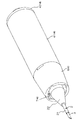
- FIG. 1 is a perspective view showing an appearance of a puncture device according to the first embodiment of the present invention.
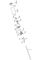
- FIG. 2 is a perspective view showing a state where the protector of the puncture device in FIG. 1 is removed.
- FIG. 3 is an exploded perspective view excluding the protector of the puncture device according to FIG. 1.
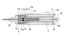
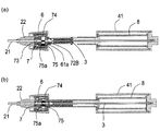
- 4 is a longitudinal sectional view showing the puncture device shown in FIG.
- FIG. 5 is a longitudinal sectional view showing the puncture device of FIG. 1, and is a longitudinal sectional view different from the longitudinal sectional view of FIG. 4 in the direction of 90 degrees.
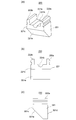
- 6A and 6B are diagrams showing an outer cylinder, in which FIG. 6A is a perspective view, FIG. 6B is a longitudinal sectional view, and FIG.
- FIG. 6C is a longitudinal sectional view different from the longitudinal sectional view of FIG. .
- FIG. 7 is a perspective view showing the inner cylinder.
- 8A and 8B are views showing a state where the inner cylinder is expanded, in which FIG. 8A is a plan view, FIG. 8B is a cross-sectional view taken along line AA of FIG. 8A, and FIG. 8C is a rear view of FIG. .
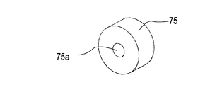
- FIG. 9 is a perspective view showing the block body.
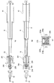
- 10A and 10B are views showing a state in which the extension of the inner needle hub for explaining the procedure for using the puncture device shown in FIG. 1 is completed, in which FIG. 10A is a longitudinal sectional view, and FIG.
- FIG. 11 is a view showing a state in which an outer needle for releasing the procedure for using the puncture device shown in FIG. 1 is released (released), where (a) is a longitudinal sectional view, and (b) is a sectional view. It is a longitudinal cross-sectional view in which the longitudinal cross-sectional view of (a) differs in a 90 degree direction.
- FIG. 12 is a perspective view showing an external appearance of a puncture device excluding the protector according to the second embodiment of the present invention.
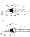
- FIG. 13 is a longitudinal sectional view showing a puncture device according to a second embodiment of the present invention, where (a) is a longitudinal sectional view, and (b) is a longitudinal section different from that of (a) by 90 degrees.
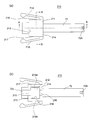
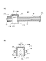
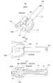
- FIG. 14A and 14B are diagrams showing the outer cylinder shown in FIG. 13, wherein FIG. 14A is a perspective view and FIG. 14B is a longitudinal sectional view.
- 15 is a view showing the inner cylinder shown in FIG. 13, wherein (a) is a perspective view, (b) is a plan view, and (c) is a longitudinal sectional view.
- FIG. 14A and 14B are diagrams showing the outer cylinder shown in FIG. 13, wherein FIG. 14A is a perspective view and FIG. 14B is a longitudinal sectional view.
- 15 is a view showing the inner cylinder shown in FIG. 13, wherein (a) is a perspective view, (b) is a plan view, and (c) is a longitudinal sectional view.
- FIG. 16 is a longitudinal cross-sectional view which shows the state which expansion
- FIG. 17 is a longitudinal cross-sectional view which shows the state which the expansion
- FIG. 18 is a longitudinal sectional view of a part of the configuration showing a state in which the inner cylinder passes through the straight portion of the rail of the outer cylinder for explaining the procedure for using the puncture device of the second embodiment of the present invention.
- (A) is a longitudinal sectional view
- (b) is a longitudinal sectional view different from the longitudinal sectional view of (a) in the direction of 90 degrees.
- FIG. 19 is a longitudinal sectional view of a part of the configuration showing a state in which the inner cylinder passes through the spiral portion of the rail of the outer cylinder for explaining the procedure for using the puncture device of the second embodiment of the present invention.
- FIG. 20 is a cross-sectional view showing a state in which the outer needle for releasing the procedure for using the puncture device of the second embodiment of the present invention is released (released).
- FIG. 21 is an exploded perspective view of the puncture device (excluding the protector) according to the third embodiment of the present invention. 22 is a view showing the outer cylinder shown in FIG. 21, wherein (a) is a perspective view, (b) is a longitudinal sectional view, and (c) is 90 ° different from the longitudinal sectional view of (b). It is a longitudinal cross-sectional view.
- FIG. 20 is a cross-sectional view showing a state in which the outer needle for releasing the procedure for using the puncture device of the second embodiment of the present invention is released (released).
- FIG. 21 is an exploded perspective view of the puncture device (excluding the protector) according to the third embodiment of the present invention. 22 is a view showing the outer cylinder shown in FIG. 21, wherein (a) is a perspective view, (b) is a longitudinal
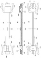
- FIG. 23 is a diagram illustrating the inner cylinder illustrated in FIG. 21, in which (a) is a perspective view and (b) is a perspective view from the bottom side of (a).
- FIG. 23 is a diagram illustrating the inner cylinder illustrated in FIG. 21, in which (a) is a plan view and (b) is a bottom view.
- 25A is a cross-sectional view taken along the line AA in FIG. 24, and
- FIG. 25B is a cross-sectional view taken along the line BB in FIG.
- 26 is a diagram showing the block body shown in FIG. 21, wherein (a) is a perspective view, (b) is a side view, and (c) is a front view.
- 27 is a view showing a puncture device showing the puncture device shown in FIG.
- FIGS. 28A and 28B are views showing a state in which the extension of the inner needle hub for explaining the procedure for using the puncture device shown in FIG. 21 is completed, in which FIG. 28A is a longitudinal sectional view, and FIG. It is a longitudinal cross-sectional view in which the longitudinal cross-sectional view of a) differs in a 90 degree direction.
- FIGS. 29A and 29B are views showing a state in which the outer needle for releasing the procedure for using the puncture device shown in FIG. 21 is released (released), where FIG.
- FIG. 30 is a view showing an inner cylinder of a puncture device according to a fourth embodiment of the present invention, in which (a) is a perspective view, (b) is a plan view, and (b) is a longitudinal sectional view.
- FIGS. 31A and 31B are views showing a state in which the inner cylinder is expanded, in which FIG. 31A is a plan view, FIG. 31B is a cross-sectional view taken along the line AA in FIG. 31A, and FIG. .
- FIG. 32 is a perspective view showing a block body of the puncture device according to the fourth embodiment of the present invention.
- FIG. 33 is a front view of the block body shown in FIG. 32.
- 34 is a longitudinal sectional view of the block body shown in FIG.
- FIGS. 35A and 35B are views showing a puncture device according to a fourth embodiment of the present invention, in which FIG. 35A is a longitudinal sectional view, and FIG. 35B is a longitudinal sectional view different from the longitudinal sectional view of FIG.
- FIG. 36 is a view showing a state in which the extension of the inner needle hub for explaining the procedure for using the puncture device shown in FIG.
- FIG. 37 is a view showing a state in which an outer needle for releasing the procedure for using the puncture device shown in FIG. 35 is released (released), wherein (a) is a longitudinal sectional view, and (b) is a sectional view. It is a longitudinal cross-sectional view in which the longitudinal cross-sectional view of (a) differs in a 90 degree direction.
- the puncture device 1 includes an outer needle 21, an inner needle 3 into which a distal end portion (left end portion on the paper surface) is inserted into the outer needle 21, and one end portion (base) of the inner needle 3. And a protector 5 that covers the outer needle 21 and the inner needle 3. Moreover, in the puncture device 1, all parts except the inner needle 3 are made of resin. In FIG. 1, the outer needle 21 and the inner needle 3 are covered with the protector 5 and cannot be seen.
- the catheter 2 includes an outer needle 21 made of a flexible hollow tube and an outer needle hub 22 that holds the proximal end portion of the outer needle 21 as shown in FIGS.
- the injection device 4 is attached to a cylindrical inner needle hub 41 and a proximal end (right end of the paper surface) of the inner needle hub 41 by press fitting. And a tail plug 42 having a substantially cylindrical needle holding portion 42a for holding the end portion.
- the injection tool 4 has an outer cylinder 6 attached to the inside of the inner needle hub 41 so as to be able to advance and retreat, and four arms 71A for gripping the outer needle hub 22. And an inner cylinder 7 attached so as to be freely advanced and retracted. In the present embodiment, the case where the four arms 71A are formed on the inner cylinder 7 is shown, but it is sufficient that the outer needle hub 22 can be held by two or more arms.
- the outer cylinder 6 includes a groove 61 formed along the axis of the shaft 64 of the outer cylinder 6 (formed along the advancing and retreating direction of the inner cylinder 7), and the four
- the arm opening / closing part 62 that accommodates the arm 71A is provided, and is formed in a cylindrical shape as a whole.
- the four arms 71A are formed so as to be able to advance and retreat while being guided by four guide groove portions 62A formed on the upper and lower portions and both sides of the inner surface of the arm opening / closing portion 62.
- the groove 61 is formed to be symmetrical at two locations, the upper portion and the lower portion, on the peripheral surface of the outer cylinder 6. 4 and 5, when the inner cylinder 7 is accommodated in the outer cylinder 6, the four arms 71A are closed and the outer needle hub 22 is closed. Grip. On the other hand, when the inner cylinder 7 is pulled out (advanced) from the outer cylinder 6, there is no restriction by the guide groove 62A (arm opening / closing section 62) as shown in FIG. The four arms 71A are opened by the generated force, and the outer needle hub 22 is released.
- the four arms 71A and the arm opening / closing part 62 constitute a gripping means for gripping the outer needle hub 22, and the four arms 71A are retracted into the arm opening / closing part 62. 4 and 5, the outer needle hub 22 is gripped, and the four arms 71A are advanced from the arm opening / closing portion 62, as shown in FIG. Thus, the outer needle hub 22 is released.
- the four arms 71 ⁇ / b> A are formed in a shape opened in advance with respect to the peripheral surface of the inner cylinder 7.
- the arm 71A of the inner cylinder 7 is inserted (accommodated) in the guide groove 62A (see FIG. 6) of the outer cylinder 6, the four arms 71A are closed by the arm opening / closing part 62. Is in a state. That is, the arm opening / closing part 62 closes the four arms 71 ⁇ / b> A so that the four arms 71 ⁇ / b> A grip the outer needle hub 22.
- the four arms 71A are extracted from the arm opening / closing part 62 as shown in FIG. Return. That is, the four arms 71A are opened by the arm opening / closing part 62, and the four arms 71A are in a state of releasing the catheter 2.
- the inner cylinder 7 passes through a neck portion 71 having the four arms 71 ⁇ / b> A, a shaft portion 72 having a diameter smaller than that of the neck portion 71, and the centers of the neck portion 71 and the shaft portion 72. And it has the through-hole 73 which penetrates the said inner needle 3, and is shape
- the shaft portion 72 is pushed up by the projecting portion 72 ⁇ / b> A that is movably accommodated in the groove portion 61 of the outer cylinder 6 and the inner needle 3 in the through hole 73, and engages with the groove portion 61.
- the diameter of the through-hole 73 is slightly larger than the diameter of the inner needle 3, and is configured to reduce the sliding resistance when the inner needle 3 is pulled out.
- the protrusions 72A are formed so as to be symmetrical at two locations on the upper surface and the lower surface of the shaft portion 72 so as to correspond to the groove portions 61 (see FIG. 4).
- the groove 61 and the protrusion 72 ⁇ / b> A regulate the advance / retreat direction of the inner cylinder 7 relative to the outer cylinder 6 (the advance / retreat direction of the outer cylinder 6 relative to the inner cylinder 7). It should be noted that when the inner cylinder 7 is advanced relative to the outer cylinder 6, the protruding portion 72A is engaged with the end 61a of the groove 61 so that the outer cylinder 6 and the inner cylinder 7 are not separated from each other. It is configured to be stopped.
- the inner cylinder 7 includes a lower portion 7A (left side of the paper surface) provided with the upright piece 72B, and an upper portion 7B (right side of the paper surface) formed on the opposite side across the center line l.
- a fold line center line 1
- groove portions 73A and 73B having a semicircular cross section are formed along the axial direction of the inner cylinder 7, respectively. These groove portions 73A and 73B are formed with one through-hole 73 by folding the lower portion 7A and the upper portion 7B.
- the upright piece 72 ⁇ / b> B is pushed out by the peripheral surface of the inner needle 3 when the inner needle 3 is inserted (accommodated) into the through-hole 73, and stands. Engage with the end of the groove 61.
- the upright piece 72B engages with the end portion on the catheter 2 side of the groove portion 61, so that it cooperates with the neck portion 71 of the inner cylinder 7 so as to sandwich the outer cylinder 6 therebetween. Locked to the outer cylinder 6.
- the upright piece 72 ⁇ / b> B is raised by the inner needle 3, and the outer cylinder 6 and the inner cylinder 7 are integrated, and the Drawing from the outer cylinder 6 is restricted.
- the upright piece 72 ⁇ / b> B rotates in a direction to block the through hole 73, (Reset) and the engagement with the groove 61 is released.
- the standing piece 72B is not locked to the outer cylinder 6 when the inner needle 3 is not present in the through-hole 73, so that the outer cylinder 6 and the inner cylinder 7 can be separated, and the outer The inner cylinder 7 can be extracted from the cylinder 6.
- the standing piece 72B when the upright piece 72B has an elastic force (restoring force), the standing piece 72B is rotated by its own elastic force (restoring force) in a direction to block the through hole 73, thereby blocking the through hole 73. To do.
- the standing piece 72B loses the elastic force (restoring force), or the elastic force (restoring force) of the standing piece 72B is weak and does not rotate in the direction of blocking the through hole 73 by its own elastic force (restoring force).
- the upright piece 72 ⁇ / b> B is caused by the end 61 a of the groove 61 of the outer cylinder 6 and rotates in a direction to block the through hole 73. Then, the through hole 73 is blocked.
- the upright piece 72B is caused to move by the end 61a of the groove 61 of the outer cylinder 6 in the direction of blocking the through-hole 73 (the arrow direction shown in FIGS. 4 and 10).
- the elastic force (restoring force) of the standing piece 72B is lost. Can be reliably shut off.
- the standing piece 72B is It is caused by the end 61a of the groove 61 of the outer cylinder 6 to rotate in the direction of blocking the through hole 73 and to block the through hole 73, so that the sliding resistance when the inner needle 3 is pulled out is reduced. Can be small.
- the neck portion 71 of the inner cylinder 7 is formed with a columnar space portion 74 that is connected to the through hole 73 through which the inner needle 3 is inserted.
- a cylindrical block body 75 in which a through hole 75a (which constitutes at least a part of the through hole 73) through which the inner needle 3 is inserted is accommodated as shown in FIG. Has been.
- the space portion 74 is formed larger than the outer diameter of the block body 75 so that the block body 75 can move in the space portion 74.
- a through hole blocking means for blocking the state is configured.
- the block body 75 is provided in the space portion 74 of the neck portion 71 of the inner cylinder 7 in this way, when the tip of the inner needle 3 passes through the through hole 75a of the block body 75, the block body 75 is removed. 75 falls and moves in the space 74 due to its own weight. Thereby, the through hole 75a is arranged at a position shifted from the extension line of the through hole 73, and the communication state of the through hole 73 can be blocked. In addition, by forming the diameter of the through-hole 75a slightly larger than that of the inner needle 3, the sliding resistance when the inner needle 3 is pulled out can be reduced.
- a relay cylinder 8 that extends the outer cylinder 6 is provided between the inner needle hub 41 and the outer cylinder 6.
- the relay cylinder 8 is not necessarily required, and may be omitted as shown in FIG.
- the pulling operation direction of the inner needle hub 41 is in an oblique direction (a direction not on the extension line of the inner needle 3). Even when a bending force is applied to the relay cylinder 8, damage such as buckling of the relay cylinder 8 can be prevented.
- the relay cylinder 8 is formed in a cylindrical shape, has an outer diameter dimension that can be accommodated in the inner needle hub 41, and an inner diameter dimension that can accommodate the outer cylinder 6 therein.
- a latching portion 8 a is formed at one end of the relay cylinder 8 and is configured to be latched by a latching portion formed at the end 63 of the outer cylinder 6.
- a locking portion 8b is formed at the other end of the relay cylinder 8, and is configured to be locked to a locking portion formed at the end portion 41a of the inner needle hub 41.
- the protector 5 is removed from the puncture device 1 shown in FIG. 1, and the catheter 2 and the inner needle 3 are exposed as shown in FIGS. Then, the outer needle 21 and the inner needle 3 are punctured into a blood vessel (a patient's body).
- the inner needle hub 41 is moved in the direction of the arrow in FIGS. 4 and 5 in the direction away from the outer needle 21 along the axial direction (withdrawing operation is performed). .
- the injection tool 4 is extended.
- the inner needle hub 41 is separated from the outer needle 21 along the axial direction in a state where the outer needle 21 is indwelled, the inner needle hub 41 moves along the axial direction, The injection device 4 is extended as a whole.
- the outer needle hub 22 is held by the inner cylinder 7, and the inner cylinder 7 and the outer cylinder 6 are integrated by the standing piece 72B.
- the inner needle hub 41 holding the rear end portion (base end portion) of the inner needle 3 is moved along the axial direction, the inner needle 3 is similarly moved along the axial direction. And by pulling out from the outer needle 21, the extracted inner needle 3 is covered in the inner cylinder 7, the outer cylinder 6, and the inner needle hub 41 (see FIG. 10).
- the block body 75 is pulled by the dead weight. Move down. Accordingly, the through hole 75a is disposed at a position shifted from the extension line of the through hole 73, and the communication state of the through hole 73 is blocked (see FIG. 10). Therefore, after the through-hole 73 is blocked by the block body 75, even if a force that moves the inner needle hub 41 toward the catheter 2 acts, the movement of the inner needle 3 is restricted by the block body 75, It does not return into the outer needle 21 again.
- the inner needle hub 41 is separated from the outer needle 21 along the axial direction.
- the upright piece 72 ⁇ / b> B does not receive a force from the side surface of the inner needle 3.
- the elastic force (restoring force) of the standing piece 72 ⁇ / b> B is weak, the standing piece 72 ⁇ / b> B is maintained in the locked state with the outer cylinder 6 without rotating in the direction of blocking the through hole 73. .
- the standing piece 72 ⁇ / b> B is caused by the end 61 a of the groove 61 of the outer cylinder 6.
- the raised standing piece 72B rotates in a direction (arrow direction in FIG. 10) that blocks the through hole 73, blocks the through hole 73, and releases the locked state with the outer cylinder 6. .
- the outer cylinder 6 and the inner cylinder 7 can be separated, and the outer cylinder 6 moves along the axial direction as the inner needle hub 41 moves. Since the groove 61 is guided by the protrusion 72 ⁇ / b> A, the inner cylinder 7 is pulled out from the outer cylinder 6 while being guided by the protrusion 72 ⁇ / b> A of the inner cylinder 7.
- the upright piece 72B is raised, even if a force for moving the inner needle hub 41 toward the catheter 2 is applied, the movement of the inner needle 3 is restricted by the upright piece 72B, and the inside of the outer needle 21 again. Will never return.
- the upright piece 72B is raised, the movement of the inner needle 3 is restricted by the upright piece 72B, and the movement of the inner needle 3 is also restricted by the block body 75. Therefore, the inner needle 3 returns to the inside of the outer needle 21 again. This can be prevented more reliably.
- the outer cylinder 6 is moved, and the inner cylinder 7 is extracted from the outer cylinder 6, as shown in FIG.
- the four arms 71A are opened to release the holding state of the outer needle hub 22 by the four arms 71A. That is, when the inner needle hub 41 is separated from the outer needle 21 along the axial direction and the injection tool 4 is extended, the inner needle 3 extracted from the catheter 2 is moved into the outer cylinder 6, When housed in the needle hub 41, the outer needle hub 22 is released from the state in which the outer needle hub 22 is held by the four arms 71A and the arm opening / closing portion 62.
- the puncture device 1 can accommodate the inner needle 3 in the inner needle hub 4 and the like only by pulling out the inner needle 3 from the outer needle 21, and the outer needle hub. 22 can be removed from the inner needle hub 41 or the like.
- the elastic force (restoring force) of the standing piece 72B is weak and the standing piece 72B is not in pressure contact with the inner needle has been described as an example.
- the elastic force (restoring force) of the standing piece 72B may be applied within a range in which the sliding resistance is not excessively increased.
- the block body 75 and the space portion 74 have been described as being cylindrical.
- the present invention is not particularly limited to this shape.
- the block body 7 may be spherical, and the space portion 74 may be formed. May be rectangular. It is sufficient that the block body 7 is movable at least in the space 74.
- the through-hole blocking means in this embodiment is configured such that when the outer cylinder moves relative to the inner cylinder, the inner cylinder and the outer cylinder rotate relative to each other.
- the through hole is configured to move from a position where the inner needle is inserted to a position where the inner needle is not inserted, and to block the communication state of the through hole.
- the puncture device 100 includes an outer needle 102, an inner needle 103 into which a distal end portion (left end portion on the paper surface) is inserted into the outer needle 102, and one end portion (base) of the inner needle 3.
- a cylindrical injection tool 104 that holds the end
- a protector (not shown) that covers the outer needle 102 and the inner needle 103.
- all parts except the inner needle 103 are made of resin.
- the catheter 101 includes an outer needle 102 made of a flexible hollow tube and an outer needle hub 102 a that holds the proximal end portion of the outer needle 102 as shown in FIGS.
- the arrangement position of the outer needle 102 in the outer needle hub 102a is formed at a position shifted from the center O of the outer needle hub 102a, as shown in FIGS.
- the injection device 104 is attached to a cylindrical inner needle hub 105 and a proximal end (right end of the paper surface) of the inner needle hub 105 by press fitting, and a proximal end portion of the inner needle 103 is And a tail plug 106 having a substantially cylindrical needle holding portion 106a to be held.
- the injection device 104 includes an outer cylinder 107 movably attached to the inside of the inner needle hub 105, and two arms 108A for holding the outer needle hub 102a. And an inner cylinder 108 that can be freely moved back and forth.
- the outer cylinder 107 includes a groove 107b formed along the axis of the shaft 107a of the outer cylinder 107 (formed along the advancing and retreating direction of the inner cylinder 7), and the two And an arm opening / closing portion 107c for accommodating the arm 108A, and is formed in a cylindrical shape as a whole.
- the center of the shaft portion 107a is formed at a position L displaced from the center line of the arm opening / closing portion 107c. That is, the shaft portion 107a is formed at a position shifted downward in the arm opening / closing portion 107c, and the center line of the arm opening / closing portion 107c does not coincide with the axis line of the shaft portion 107a.
- the groove 107 b is formed so as to be symmetrical at two locations, the upper part and the lower part, on the peripheral surface of the outer cylinder 107.
- FIG. 13A when the inner cylinder 108 is accommodated in the outer cylinder 107, the two arms 107A are closed and the outer needle hub 102a is closed. Grip.
- the inner cylinder 108 is pulled out (advanced) from the outer cylinder 107, as shown in FIG. 20, there is no restriction by the arm opening / closing portion 107c.
- the arm 108A is opened to release the outer needle hub 102a.
- a groove 107d is formed on the inner peripheral surface of the arm opening / closing portion 107c to which a projection 108F formed on the outer surface of the inner cylinder 108 is movably attached.
- a pair of the groove portions 107d are formed symmetrically, and a linear portion 107d1 having a linear groove is formed on the shaft portion 107a side, and subsequently, a spiral portion 107d2 having a spiral groove is formed.
- the inner cylinder 108 penetrates the neck portion 108B having the two arms 108A, the shaft portion 108C having a diameter smaller than that of the neck portion 108B, and the neck portion 108B and the shaft portion 108C. And a through hole 108D through which the inner needle 3 is inserted.
- the shaft portion 108C is formed at a position displaced from the center line of the neck portion 108B. That is, the shaft portion 108C is formed at a position shifted downward from the neck portion 108B, and the center line of the neck portion 108B does not coincide with the axis line of the shaft portion 108C.
- the through hole 108 ⁇ / b> D formed in the inner cylinder 108 is formed at a position L (displaced position) away from the central axis of the inner cylinder 108. Further, when the neck portion 108B of the inner cylinder 108 is accommodated in the arm opening / closing portion 107c of the outer cylinder 107, the shaft portion 108C is configured to be accommodated in the shaft portion 107a of the outer cylinder 107.
- the shaft portion 108C is provided with an upright piece 108E that is pushed up by the inner needle 103 in the through hole 108D to stand up and engage with the groove portion 107b. Since the upright piece 108E is the same as the upright piece 72B of the first embodiment, detailed description thereof is omitted here.
- the diameter of the through hole 108D is slightly larger than the diameter of the inner needle 3, and is configured to reduce the sliding resistance when the inner needle 3 is pulled out.
- a pair of protrusions 108F are provided on the outer peripheral surface of the end portion of the neck portion 108B on the shaft portion 108C side.
- the pair of protrusions 108F are formed to be symmetrical so as to correspond to the grooves 107d (see FIG. 15).
- the through hole 108D formed in the inner cylinder 108 is formed at a position L away from the central axis of the inner cylinder 108, and the through hole blocking means is formed as a spiral formed on the inner surface of the outer cylinder 107.
- the inner cylinder 108 and the outer cylinder 107 are relatively formed by forming the groove 107d including a shape portion and the protrusion 108F formed on the outer surface of the inner cylinder 108 and movable in the groove 107d.
- the through hole 108D of the inner cylinder 108 can be moved from a position where the inner needle 103 is inserted to a position where the inner needle 103 is not inserted.
- the pair of protrusions 108F move along the groove 107d of the outer cylinder 108 and the arm 108A is expanded, the pair of protrusions are formed at the end of the spiral portion 107d2 of the groove 107d of the outer cylinder 107.
- the advance and retreat of the inner cylinder 108 with respect to the outer cylinder 107 is restricted. That is, the outer cylinder 107 and the inner cylinder 108 are configured not to be separated from each other.
- a relay cylinder 109 that extends the outer cylinder 107 is provided between the inner needle hub 105 and the outer cylinder 107.
- the relay cylinder 109 is the same as that of the first embodiment, and detailed description thereof is omitted here.
- the puncture device 100 As in the first embodiment, an example in which the elastic force (restoring force) of the standing piece 102E is weak and the standing piece 102E is not in pressure contact with the inner needle 103 will be described.
- the protector is removed from the puncture device 100, and the catheter 101 and the inner needle 103 are exposed as shown in FIG. Then, the outer needle 102 and the inner needle 103 are punctured into a blood vessel (a patient's body).
- the inner needle hub 105 is moved in the direction of the arrow in FIG. 13 in the direction away from the outer needle 102 along the axial direction (withdrawing operation is performed). By the pulling-out operation of the inner needle hub 105, the injection tool 104 is extended.
- the inner needle hub 105 that holds the rear end portion (base end portion) of the inner needle 103 is moved along the axial direction, the inner needle 103 is similarly moved along the axial direction. Then, by pulling out from the outer needle 102, the extracted inner needle 103 is covered in the outer cylinder 107 and the inner needle hub 105 (see FIG. 16).
- the inner needle hub 105 is separated from the outer needle 102 along the axial direction. Then, as shown in FIG. 16, when the tip of the inner needle 103 passes through the upright piece 108 ⁇ / b> E, the upright piece 108 ⁇ / b> E is not subjected to force from the side surface of the inner needle 103. At this time, since the elastic force (restoring force) of the upright piece 108E is weak, the upright piece 108E does not rotate in the direction of blocking the through hole 108D, and the locked state with the outer cylinder 107 is maintained. .
- the relay cylinder 109 is pulled out from the inner needle hub 105, and thereafter, the locking portion 109 a of the relay cylinder 109 is brought into contact with the locking portion formed at the end portion 105 a of the inner needle hub 105.
- the upright piece 108E is caused by the end 107b1 of the groove 107b of the outer cylinder 107.
- the raised standing piece 108E rotates in a direction to block the through hole 108D, blocks the through hole 108D, and releases the locked state with the outer cylinder 107.
- the outer cylinder 107 and the inner cylinder 108 can be separated, and the outer cylinder 107 moves along the axial direction as the inner needle hub 105 moves.
- the inner needle 103 is moved by the standing piece 72B. The movement is restricted, and it does not return into the outer needle 21 again.
- the protrusion 108F of the inner cylinder 108 is formed in the groove 107d of the outer cylinder 107. It moves while being guided by the straight line portion 107d1. Subsequently, when the protrusion 108F of the inner cylinder 108 moves while being guided by the spiral portion 107d2 of the groove 107d of the outer cylinder 107, as shown in FIG. 19, the inner cylinder 108 and the outer cylinder 107 rotate relatively. . Actually, the outer cylinder 107 rotates with respect to the inner cylinder 108 holding the fixed catheter 101.
- the through hole 108 ⁇ / b> D of the inner cylinder 108 moves from a position where the inner needle 103 is inserted to a position where the inner needle 103 is not inserted, thereby blocking the communication state of the through hole 103.
- the inner needle hub 105 is separated from the outer needle 102 along the axial direction and the injection device 104 is extended, the inner needle 103 extracted from the catheter 101 is moved into the outer cylinder 107, When accommodated in the needle hub 105 (or in some cases, the relay cylinder 109), the outer needle hub 102a is released from the holding state of the outer needle hub 102a by the arm 108A and the arm opening / closing portion 107c.
- the puncture instrument 100 can accommodate the inner needle 103 in the inner needle hub 105 only by pulling out the inner needle 103 from the outer needle 102, and the outer needle hub 102a. Can be removed from the inner needle hub 105.
- the groove 107d is formed on the inner surface of the outer cylinder 107 and the protrusion 108F is formed on the inner cylinder 108 has been described.
- a groove may be formed in the inner cylinder and a protrusion may be formed in the outer cylinder.
- the through hole blocking means in this embodiment includes a block body in which a through hole through which an inner needle is inserted is formed, and a space portion formed in an inner cylinder that is movably accommodated with the block body, and the inner needle
- the block body moves in the space portion by a projection formed on the inner surface of the outer cylinder, and the insertion of the inner needle It is characterized in that it is configured so that the (through hole through which the inner needle is inserted) is blocked.
- the outer cylinder 201, the inner cylinder 210, and the block body 220 are different from the outer cylinder 6, the inner cylinder 7, and the block body 7 of the first embodiment. That is, as shown in FIGS. 21 and 22, the outer cylinder 201 is formed with a tongue-like piece 202 surrounded by a through-hole 203 having a U-shape in plan view in an arm opening / closing portion 204 that accommodates two arms 71A. In addition, a protrusion 205 protruding inward is formed at the tip of the tongue-like piece 202.
- the tongue-like piece 202 is arranged so that the base end portion of the tongue-like piece 202 is located on the distal end side of the outer cylinder 201.
- a protrusion 205 formed at the tip of the tongue-shaped piece 202 is in contact with the block body 220 and moves the block body 220 upward when the inner cylinder 210 moves in the outer cylinder 201.
- the inner cylinder 210 includes a rectangular parallelepiped neck portion 211 including the two arms 71A, and a cylindrical shaft having an outer dimension smaller than that of the neck portion 211. Part 72 and a through hole 73 that penetrates the center of the neck part 211 and the shaft part 72 and allows the inner needle 3 to be inserted therethrough.
- the neck portion 211 of the inner cylinder 210 is formed with a concave space portion 212 in which one surface connected to the through hole 73 through which the inner needle 3 is inserted is opened.
- the front wall 213 and the rear wall 214 of the neck portion 211 are formed with notches 215 and 216 opened to the open surface side of the recessed space portion 211.
- a flat surface portion 72 ⁇ / b> C is formed on the side of the notch 215 in the shaft portion 72 formed on the distal end side of the neck portion 211.
- the space 212 is a space for accommodating the block body 220, and is formed larger than the outer diameter of the block body 220 so that the block body 220 can move in the space 212.
- protrusions 219a and 219b projecting toward the space 212 are formed on the inner surfaces of the side wall 217 and the side wall 218 of the neck 211.
- the protrusions 219a and 219b are disposed on the rear side of the through hole 73 as viewed from the open surface side of the concave space 211, and extend in parallel with the axis of the through hole 73. ing.
- the protrusions 219a and 219b are for locking the block body 220 after the block body 220 has moved.
- the block body 220 has a semicircular recess 221b formed on the upper surface 221a of the main body 221 and further provided with claw portions 222a and 222b protruding upward from the upper surface 221a.
- the concave portion 221b is formed in the front-rear direction of the main body portion 221, and when the block body 220 is accommodated in the space portion 211, the inner needle 3 contacts and the inner needle 3 slides in the concave portion 221b. Is configured to do.
- the claw portions 222a and 222b are fixed to the space portion 212 by being locked to the protrusions 219a and 219b when the block body 220 moves in the space portion 212.
- the block body 220 is prevented from moving.
- the front surface 221c of the main body 221 is formed as an inclined surface 221e that inclines downward from the front surface 221c side toward the rear surface 221d side.
- the inclined surface 221e of the main body 221 is accommodated in the space 212 so as to be in contact with the protrusion 205 at the tip of the tongue-like piece 202. That is, the protrusion 205 enters the space 212 from the recess 215 and contacts the inclined surface 221e.
- the through hole blocking means is constituted by the space 212, the block body 220, and the outer cylinder 201.
- the block body 220 moves into the space 212 by the protrusion 205. Is pushed (moved) from the state in which the inner needle 3 is inserted to the state in which the inner needle 3 is not inserted, and the communication state of the through hole 73 is blocked.
- the protector 5 is removed from the puncture device 200, and the catheter 2 and the inner needle 3 are exposed as shown in FIG. Then, the outer needle 21 and the inner needle 3 are punctured into a blood vessel (a patient's body).
- the inner needle hub 41 is moved in the direction of the arrow in FIG. 27 in the direction away from the outer needle 21 along the axial direction (withdrawing operation is performed).
- the inner needle hub 41 that holds the rear end portion (base end portion) of the inner needle 3 is moved along the axial direction, the inner needle 3 is similarly moved along the axial direction.
- the pulled out inner needle 3 is covered in the inner cylinder 210, the outer cylinder 201, and the inner needle hub 41.
- the inner needle hub 41 when the inner needle hub 41 is moved away from the outer needle 21 along the axial direction, as shown in FIG. 29, the claw portions 222a and 222b of the block body 220 pushed upward are locked to the protrusions 219a and 219b. As a result, the block body 220 is fixed, and the blocking state is fixed. Therefore, after the claw portions 222a and 223b of the block body 220 are locked to the protrusions 219a and 219b, the inner needle hub 41 is moved to the catheter 2 side after the through hole 73 is blocked by the block body 220. Even if a force acts, the movement of the inner needle 3 is restricted by the block body 220 and does not return into the outer needle 21 again.
- the two arms 71A are opened as shown in FIG.
- the holding state of the outer needle hub 22 by the two arms 71A is released. That is, when the inner needle hub 41 is separated from the outer needle 21 along the axial direction and the injection device 4 is extended, the inner needle 3 extracted from the catheter 2 is moved into the outer cylinder 201, When housed in the needle hub 41, the outer needle hub 22 is released from the holding state of the outer needle hub 22 by the two arms 71A and the arm opening / closing portion 62.
- the puncture device 1 can accommodate the inner needle 3 in the inner needle hub 4 and the like only by pulling out the inner needle 3 from the outer needle 21, and the outer needle hub. 22 can be removed from the inner needle hub 41 or the like.
- the through-hole blocking means in this embodiment comprises a block body formed with a through-hole through which an inner needle is inserted, and a space portion formed in an inner cylinder that rotatably accommodates the block body.
- the block body is configured to rotate in the space portion by a protrusion formed on the inner surface of the outer cylinder, and the insertion of the inner needle is blocked.
- the block body is configured to be movable in the vertical direction, whereas in the fourth embodiment, the block body is configured to be rotatable.
- symbol is attached
- the inner cylinder 301 will be described.
- the inner cylinder 301 and the block body 310 are different from the inner cylinder 210 and the block body 220 of the third embodiment.
- the outer cylinder has the same configuration as that of the third embodiment.
- the inner cylinder 301 includes a rectangular parallelepiped neck 302 having the two arms 71A, a cylindrical shaft 72 having an outer dimension smaller than the neck 302, and the It has a through hole 73 that penetrates the center of the neck portion 302 and the shaft portion 72 and allows the inner needle 3 to be inserted therethrough.
- a space 303 is formed inside the neck 302 so as to connect to the through hole 73 through which the inner needle 3 is inserted.
- the space 303 is a space for accommodating a block body 310 in which a through hole 75a through which the inner needle 3 is inserted is formed as shown in FIG.
- the space portion 303 is formed in a substantially cylindrical shape larger than the outer diameter of the block body 310 so that the block body 310 can move in the space portion 303.
- the space portion 303 includes a first columnar space portion 303a in which the main body of the block body 310 is accommodated, and a second columnar space portion formed on the left and right sides of the first columnar space portion 303a. 303b.
- the second cylindrical space 303b is a space in which the rotation shaft of the block body 310 is accommodated.
- the upper wall 302a of the neck 302 is formed with a recess 302b extending in the front-rear direction (axial direction of the through hole 73), and an opening 303c of the space 303 is formed on the bottom surface of the recess 302b.
- a protrusion 304 protruding into the space 303 is formed on the inner wall surface of the neck 302 that forms the space 303a.
- the protrusion 304 is for locking the block body 310 and extends in a direction perpendicular to the axis of the through hole 73.
- the inner cylinder 301 is a component in which an upper part 301A (left side of the paper) and a lower part 301B (right side of the paper) formed on the opposite side across the center line 1 are integrally formed. And the upper part 301A and the lower part 301B are folded around a fold line (center line 1). Further, in the center of the upper portion 301A and the lower portion 301B, groove portions 73A and 73B having semicircular cross sections are formed along the axial direction of the inner cylinder 301, respectively. These groove portions 73A and 73B are formed with one through-hole 73 by folding the lower portion 7A and the upper portion 7B.
- neck portions 302A and 302B are formed at the ends of the upper portion 301A and the lower portion 301B, respectively.
- the neck portions 302A and 302B are respectively formed with concave portions 303A and 303B having a semicircular cross section, and a single space portion 303 is formed by folding the upper portion 301A and the lower portion 301B.
- an arm 71A1 and an arm 71A2 are formed on each of the neck portions 302A and 302B, and two arms 71A are formed on the neck portion 302 by folding the upper portion 301A and the lower portion 301B.
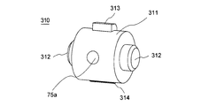
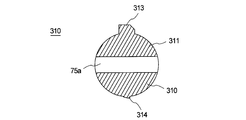
- the block body 310 includes a columnar main body 311 and shaft portions 312 formed on both end surfaces of the main body 311.
- a through hole 75 a through which the inner needle 3 is inserted is formed in the cylindrical main body 311 in a direction orthogonal to the axis of the main body 311.
- a protrusion 313 is formed on the peripheral surface of the cylindrical main body 311 so as to protrude from the opening 303c of the space 303 into the recess 302b. Since the tip of the protrusion 313 protrudes into the recess 302b, the protrusion 205 (see FIG. 22) formed on the outer cylinder 201 is moved as the inner cylinder 301 moves relative to the outer cylinder. The block body 310 is rotated in contact with the protrusion 313.
- a claw portion 314 that engages with the protrusion 304 is provided on the peripheral surface of the cylindrical main body portion 311. Further, the claw portion 314 is locked to the projection 304 when the block body 310 rotates the space portion 303, thereby fixing the block body 310 to the space portion 303. This prevents the rotation. Thus, the projection 205 of the outer cylinder 201 rotates the block body 310 from a position where the inner needle 3 is inserted to a position where the inner needle 3 is not inserted, thereby blocking the communication state of the through hole 73.
- the protector 5 is removed from the puncture device 300, and the catheter 2 and the inner needle 3 are exposed as shown in FIG. Then, the outer needle 21 and the inner needle 3 are punctured into a blood vessel (a patient's body).
- the inner needle hub 41 is moved in the direction of the arrow in FIG. 35 in the direction away from the outer needle 21 along the axial direction (withdrawing operation is performed).
- the inner needle hub 41 that holds the rear end portion (base end portion) of the inner needle 3 is moved along the axial direction, the inner needle 3 is similarly moved along the axial direction.
- the pulled out inner needle 3 is covered in the inner cylinder 301, the outer cylinder 210, and the inner needle hub 41.
- the inner needle hub 41 when the inner needle hub 41 is moved away from the outer needle 21 along the axial direction, the inner cylinder 301 moves in the outer cylinder 210 (the outer cylinder 210 moves relative to the inner cylinder 301), and The protrusion 205 comes into contact with the protrusion 313 of the block body 310 and rotates the block body 310 (see FIG. 36).
- the through hole 75a of the block body 310 is also rotated, and the through hole 75a is disposed at a position shifted from the extension line of the through hole 73. This communication state is blocked (see FIG. 36B). Thereby, even if the force which moves the inner needle hub 41 to the catheter 2 side acts, the movement of the inner needle 3 is regulated by the block body 220 and does not return into the outer needle 21 again.
- the claw portion 314 of the block body 310 is locked to the protrusion 304 as shown in FIG.
- the blocking state is fixed, and the block body 310 is prevented from rotating.
- the block body 310 does not rotate, so that the through-hole 73 is reliably blocked, and the force that moves the inner needle hub 41 to the catheter 2 side.
- the inner needle 3 is restricted from moving by the block body 220 and does not return into the outer needle 21 again.
- the puncture device 1 can accommodate the inner needle 3 in the inner needle hub 4 and the like only by pulling out the inner needle 3 from the outer needle 21, and the outer needle hub. 22 can be removed from the inner needle hub 41 or the like.
Landscapes
- Health & Medical Sciences (AREA)
- Life Sciences & Earth Sciences (AREA)
- Surgery (AREA)
- Veterinary Medicine (AREA)
- Public Health (AREA)
- General Health & Medical Sciences (AREA)
- Engineering & Computer Science (AREA)
- Biomedical Technology (AREA)
- Heart & Thoracic Surgery (AREA)
- Animal Behavior & Ethology (AREA)
- Molecular Biology (AREA)
- Medical Informatics (AREA)
- Nuclear Medicine, Radiotherapy & Molecular Imaging (AREA)
- Pathology (AREA)
- Biophysics (AREA)
- Pulmonology (AREA)
- Anesthesiology (AREA)
- Hematology (AREA)
- Gastroenterology & Hepatology (AREA)
- Infusion, Injection, And Reservoir Apparatuses (AREA)
- Media Introduction/Drainage Providing Device (AREA)
- Measurement Of The Respiration, Hearing Ability, Form, And Blood Characteristics Of Living Organisms (AREA)
Abstract
Description
この穿刺具は、圧縮されたコイルバネを開放することで、プロテクタ本体が摺動し、プロテクタ本体により、ハブに固定された針の先端を保護するようになされている。
特許文献2、3に記載されている穿刺具は、外針と、外針を保持する外針ハブと、外針に先端部が挿入される内針と、内針の基端部を内部に保持する筒状の内針ハブとを備え、外針を血管に留置した後、内針を内針ハブ内部に収容し、収容した内針が内針ハブ内部から突出しないように構成されている。
具体的には、内針の内部通路を閉塞する弾性部材からなる針止部材が設けられ、内針が内針ハブ内部に収容された際、前記針止部材の復元力によって、内針の内部通路を閉塞し、内針ハブ内に収容された内針が、前記内針ハブから外部に突出しないようになされている。
このように、前記針止部材が内針の外周面に圧接しているため、使用者(術者)の外針からの内針引抜き操作の際、針止部材の復元力(弾性力)が摺動抵抗となり、内針の引抜き操作を容易に行うことができないという課題があった。
一方、針止部材の復元力(弾性力)を小さくし、内針の引抜き操作の際の摺動抵抗を小さくすると、針止部材が内部通路全体に拡開せず、内部通路を完全に閉塞できないために、内針が外部に突出する虞があった。
一方、針止部材を、ポリエチレン等の合成樹脂で形成した場合には、コスト的には好ましいが、内針の引抜き操作の際、内部通路を十分に閉塞できず、内針が外部に突出する虞があった。即ち、針止部材が内針の外周面に圧接している状態(外針からの内針の引抜き操作が行われる前)にあっては、針止部材は変形状態にある。そのため、穿刺具が長期間保管されていた等、未使用の期間が長い場合には、前記針止部材が塑性変形し、内針引抜き操作の際、針止部材が十分に拡開せず、内部通路を閉塞できず、内針が外部に突出する虞があった。
また、従来の針止部材のように内針に圧接させる必要がないため、内針の引抜き操作の際の摺動抵抗を小さくすることができ、引抜き操作を容易に行うことができる。
また、従来の針止部材のように復元力を用いていないため、穿刺具が長期間保管されていた等、未使用の期間が長い場合においても、塑性変形等を起こすこともなく、前記内筒の貫通孔の連通状態を確実に遮断することができる。
更に、ブロック体の貫通孔を内針径よりも僅かに大きく形成することにより、内針の引抜き操作の際の摺動抵抗を小さくすることができ、引抜き操作を容易に行うことができる。
このように、前記係止が解除された起立片によって、前記内筒の貫通孔の連通状態をより確実に遮断することができ、内針の外部への突出をより確実に防止することができる。
また、従来の針止部材のように復元力を用いていないため、穿刺具が長期間保管されていた等、未使用の期間が長い場合においても、塑性変形等を起こすこともなく、内針の外部への突出を防止することができる。
更に、前記内筒の貫通孔を内針径よりも僅かに大きく形成することにより、内針の引抜き操作の際の摺動抵抗を小さくすることができ、容易に引抜き操作を行うことができる。
また、少なくとも外筒及び内筒が合成樹脂で形成されていることが望ましい。
また、従来の針止部材のように復元力を用いていないため、穿刺具が長期間保管されていた等、未使用の期間が長い場合においても、塑性変形等を起こすこともなく、前記内筒の貫通孔の連通状態を確実に遮断することができる。
更に、ブロック体の貫通孔を内針径よりも僅かに大きく形成することにより、内針の引抜き操作の際の摺動抵抗を小さくすることができ、引抜き操作を容易に行うことができる。
このように、ブロック体の移動阻止手段が形成されているため、内針の挿通が遮断された状態が固定化され、より確実に、内針の挿通を遮断することができる。
また、外筒、内筒、ブロック体が合成樹脂で形成されていることが望ましい。外筒、内筒、ブロック体がポリエチレン等の合成樹脂で形成されることにより、安価に製作することができる。
穿刺具1は、図1および図2に示すように、外針21と、前記外針21に先端部(紙面左端部)が挿入される内針3と、前記内針3の一端部(基端部)を保持する筒状の注射具4と、前記外針21および前記内針3を覆うプロテクタ5とを備えている。また、前記穿刺具1において、前記内針3を除く全ての部品は樹脂製である。尚、図1では、前記外針21および前記内針3は、前記プロテクタ5に覆われて見ることができない。
また、前記カテーテル2は、図2、3に示すように可撓性を有する中空の管からなる外針21と、外針21の基端部を保持する外針ハブ22とを有する。
尚、本実施形態では、前記内筒7に、前記4つのアーム71Aが形成された場合を示しているが、2つ以上のアームで外針ハブ22を保持できれば良い。
尚、前記4つのアーム71Aは、前記アーム開閉部62の内面の上下部、両側部に形成された4つのガイド溝部62Aに、案内されながら進退可能に形成されている。
また、前記アーム開閉部62は、図4、図5に示すように、前記外筒6に前記内筒7が収容されている場合には、前記4つのアーム71Aは閉じられ前記外針ハブ22を把持する。
一方、前記外筒6から前記内筒7が引抜かれた(進出した)場合には、図11に示すように、ガイド溝部62A(アーム開閉部62)による規制がなくなるため、アーム71A自体の弾発力により、前記4つのアーム71Aは開き、前記外針ハブ22を解放する。
そして、前記外筒6のガイド溝62A(図6参照)に、前記内筒7のアーム71Aを挿入(収容)されている場合には、前記4つのアーム71Aは前記アーム開閉部62によって閉じた状態になされている。即ち、前記アーム開閉部62は、前記4つのアーム71Aを閉じ、前記4つのアーム71Aが前記外針ハブ22を把持する状態になされている。
前記軸部72は、前記外筒6の前記溝部61内を移動可能に収容される突出部72Aと、前記貫通孔73内の内針3によって押し出されて起立し、前記溝部61に係合する起立片72Bとを備えている。
尚、前記貫通孔73の径は、内針3の径よりも僅かに大きく形成され、内針3の引抜き操作の際の摺動抵抗を小さくように構成されている。
尚、前記内筒7を前記外筒6に対して進出させた際、前記外筒6および内筒7は互いに分離することのないように、溝部61の端部61aに前記突出部72Aが係止されるように構成されている。
また、前記下部7Aおよび前記上部7Bの中央には、前記内筒7の軸線方向に沿って断面半円状の溝部73A,73Bがそれぞれ形成されている。これらの溝部73A,73Bは、前記下部7Aおよび前記上部7Bを折り畳むことによって、一つの貫通孔73が形成される。
ここで、前記起立片72Bは、前記溝部61のうち、前記カテーテル2側の端部に係合するので、前記内筒7の前記首部71と共働して前記外筒6を挟み込むようにして前記外筒6に係止される。
換言すれば、前記起立片72Bは、前記貫通孔73に内針3が存在する場合には、前記内針3によって起立し、外筒6と内筒7が一体となり、前記内筒7の前記外筒6からの引抜きが規制される。
換言すれば、前記起立片72Bは、前記貫通孔73に内針3が存在しない場合には、前記外筒6に係止されないため、外筒6と内筒7とが分離可能となり、前記外筒6から前記内筒7を引抜くことができる。
一方、起立片72Bが弾性力(復元力)を失い、あるいは起立片72Bの弾性力(復元力)が弱く、自らの弾性力(復元力)によって前記貫通孔73を遮断する方向に回動しない場合であっても、外筒6から内筒7が分離する際、前記起立片72Bは、外筒6の溝部61の端部61aによって引き起こされて、前記貫通孔73を遮断する方向に回動し、前記貫通孔73を遮断する。
また、起立片72Bと内針3との圧接力を弱く設定している場合(起立片72Bの弾性力(復元力)が弱く接している場合)にも、前記したように起立片72Bは、外筒6の溝部61の端部61aによって引き起こされて、前記貫通孔73を遮断する方向に回動し、前記貫通孔73を遮断するため、内針3の引抜き操作の際の摺動抵抗を小さくすることができる。
また、前記空間部74には、図9に示すような、前記内針3が挿通する貫通孔75a(貫通孔73の少なくとも一部を構成する)が形成された円柱状のブロック体75が収容されている。この空間部74は、空間部74内においてブロック体75が移動できるように、ブロック体75の外径よりも大きく形成されている。
尚、前記貫通孔75aの径を内針3よりも僅かに大きく形成することにより、内針3の引抜き操作の際の摺動抵抗を小さくすることができる。
例えば、柔軟な合成樹脂で形成すること等により、柔軟性を付与した中継筒8を設けることにより、内針ハブ41の引抜き動作方向が、斜め方向(内針3の延長線上ではない方向)になされ、中継筒8に曲げ力が加わった場合にも、中継筒8が座屈する等の破損を防止することができる。
この中継筒8の一端には係止部8aが形成され、外筒6の端部63に形成された係止部に係止されるように構成されている。またこの中継筒8の他端には係止部8bが形成され、内針ハブ41の端部41aに形成された係止部に係止されるように構成されている。
尚、中継筒8が設けられていない場合には、前記内針ハブ41の端部41aの係合部が、前記外筒6の端部63の係合部に係止することによって、互いに分離(離間)することのないように構成される。
まず、図1に示す穿刺具1からプロテクタ5を外し、図4、図5に示すようにカテーテル2および内針3を露出させる。そして、前記外針21および前記内針3を血管(患者の身体)に穿刺する。
具体的には、前記外針21を留置した状態において、前記内針ハブ41を軸方向に沿って前記外針21から離間させると、前記内針ハブ41が軸方向に沿って移動し、前記注射具4は全体として伸長することになる。このとき、外針ハブ22は内筒7によって保持され、内筒7と外筒6は起立片72Bによって一体化している。
したがって、ブロック体75によって、貫通孔73が遮断された後は、内針ハブ41をカテーテル2側に移動させる力が作用しても、内針3は、前記ブロック体75によって移動が規制され、再び外針21内に戻ることはない。
その結果、外筒6と内筒7が分離可能となり、前記内針ハブ41の移動に伴って、前記外筒6が軸方向に沿って移動することになる。前記溝部61は前記突出部72Aに案内されるため、前記内筒7の突出部72Aに案内されながら、前記内筒7は外筒6から引抜き出される。
このように、起立片72Bが引き起こされた後は、内針3は、前記起立片72Bによって移動が規制され、更に前記ブロック体75によっても移動が規制されるため、再び外針21内に戻ることを、より確実に防止することができる。
即ち、前記内針ハブ41を軸方向に沿って前記外針21から離間させて前記注射具4を伸長させることによって、前記カテーテル2から抜出された前記内針3が前記外筒6、内針ハブ41の内部に収容されると、前記4つのアーム71Aとアーム開閉部62による外針ハブ22の保持状態から、外針ハブ22を解放する。
このように、前記穿刺具1は、前記内針3を前記外針21から引抜き動作のみによって、前記内針3を前記内針ハブ4等の内部に収容することができ、しかも前記外針ハブ22を前記内針ハブ41等から取り外すことができる。
この実施形態における貫通孔遮断手段は、前記内筒に対して外筒が移動すると、前記内筒と外筒とが相対的に回転するように構成され、前記回転に伴って、前記内筒の貫通孔が、内針が挿通する状態における位置から内針が挿通しない位置に移動し、前記貫通孔の連通状態を遮断するように構成されている点に特徴がある。
尚、外針ハブ102aにおける外針102の配置位置は、図12、図13(b)に示すように、外針ハブ102aの中心Oからずれた位置に形成されている。
前記軸部107aの中心は、図14(b)に示すように、アーム開閉部107cの中心線から変位した位置Lに形成されている。即ち、前記軸部107aは、アーム開閉部107cの下方向にずれた位置に形成され、アーム開閉部107cの中心線と軸部107aの軸線は一致していない。
また、前記アーム開閉部107cは、図13(a)に示すように、前記外筒107に前記内筒108が収容されている場合には、前記2つのアーム107Aは閉じられ前記外針ハブ102aを把持する。
一方、前記外筒107から前記内筒108が引抜かれた(進出した)場合には、図20に示すように、アーム開閉部107cによる規制がなくなるため、アーム108A自体の弾発力により、前記アーム108Aは開き、前記外針ハブ102aを解放する。
この溝部107dは、左右対称に一対形成されており、軸部107a側に溝が直線状の直線部107d1が形成され、続いて溝が螺旋状の螺旋部107d2が形成されている。
前記軸部108Cは、図15(c)に示すように、前記首部108Bの中心線から変位した位置に形成されている。即ち、前記軸部108Cは、首部108Bの下方向にずれた位置に形成され、首部108Bの中心線と軸部108Cの軸線は一致していない。
このように、前記内筒108に形成された貫通孔108Dは、内筒108の中心軸から離れた位置L(変位した位置)に形成されている。
また、前記内筒108の首部108Bを外筒107のアーム開閉部107c内に収容した際、前記軸部108Cは、外筒107の軸部107a内に収容されるように構成されている。
この起立片108Eは、第1の実施形態の起立片72Bと同一であるため、ここでは詳細な説明は省略する。尚、前記貫通孔108Dの径は、内針3の径よりも僅かに大きく形成され、内針3の引抜き操作の際の摺動抵抗を小さくように構成されている。
そして、前記内筒108が外筒107に対して移動する際、一対の突起部108Fが外筒108の溝部107dに沿って移動するため、前記内筒108と外筒107は相対的に回転する。
まず、穿刺具100からプロテクタを外し、図13に示すようにカテーテル101および内針103を露出させる。そして、前記外針102および前記内針103を血管(患者の身体)に穿刺する。
その結果、外筒107と内筒108が分離可能となり、前記内針ハブ105の移動に伴って、前記外筒107が軸方向に沿って移動することになる。
続いて、内筒108の突起部108Fが、図19に示すように、外筒107の溝部107dの螺旋部107d2に案内されながら移動すると、内筒108と外筒107とが相対的に回転する。実際は、固定されているカテーテル101を把持している内筒108に対して、外筒107が回転する。
その結果、前記内筒108の貫通孔108Dが、内針103が挿通する状態における位置から、内針103が挿通しない位置に移動し、前記貫通孔103の連通状態を遮断する。
即ち、前記内針ハブ105を軸方向に沿って前記外針102から離間させて前記注射具104を伸長させることによって、前記カテーテル101から抜出された前記内針103が前記外筒107、内針ハブ105(場合によっては、中継筒109)の内部に収容されると、前記アーム108Aとアーム開閉部107cによる外針ハブ102aの保持状態から、外針ハブ102aを解放する。
このように、前記穿刺具100は、前記内針103を前記外針102から引抜き動作のみによって、前記内針103を前記内針ハブ105の内部に収容することができ、しかも前記外針ハブ102aを前記内針ハブ105から取り外すことができる。
更に、内筒108と外筒107とを相対的に回転させ、前記内筒108の貫通孔108Dを、内針103が挿通する状態における位置から、内針103が挿通しない位置に移動させることにより、前記貫通孔103を遮断するため、再び外針102内に戻ることはない。
したがって、起立片108E及び内筒108の貫通孔108Dの移動により、内針103の挿通が規制されるため、内針103が外針21内に再び戻ることをより確実に防止することができる。
この実施形態における貫通孔遮断手段は、内針が挿通する貫通孔が形成されたブロック体と、前記ブロック体と移動可能に収容する、内筒に形成された空間部とからなり、前記内針の先端が前記ブロック体を通過して引き抜かれ、外筒に対して前記内筒が移動すると、前記ブロック体が外筒内面に形成された突起により前記空間部内を移動し、前記内針の挿通(内針が挿通する貫通孔)が遮断されるように構成されている点に特徴がある。尚、第1の実施形態と同一、あるいは相当する部材については、同一の符号を付することにより、その詳細な説明は省略する。
即ち、前記外筒201は、図21、図22に示すように、2つのアーム71Aを収容するアーム開閉部204において、平面視がコ状の貫通孔203によって囲まれた舌状片202が形成され、前記舌状片202の先端部に、内方に突出した突起205が形成されている。また、前記舌状片202の基端部が前記外筒201の先端部側に位置するように、前記舌状片202が配置されている。
前記舌状片202の先端部に形成された突起205は、ブロック体220と接し、内筒210が外筒201内を移動する際、前記ブロック体220を上方に移動させるものである。
この内筒210は、図21、図23、図24、図25に示すように、前記2つのアーム71Aを備えた直方体状の首部211と、前記首部211よりも外形寸法が小さい円筒状の軸部72と、前記首部211および前記軸部72の中心を貫通し、前記内針3を挿通させる貫通孔73とを有している。
また前記首部211の前壁213及び後壁214には、凹部状の空間部211の開放面側に開放された切欠き部215、216が形成されている。
更に、前記首部211の先端側に形成された軸部72における前記切欠き部215側には、平面部72Cが形成されている。
また、前記首部211の側壁217及び側壁218の内面には、前記空間部212側に突出する突起219a,219bが形成されている。この突起219a,219bは、図25に示すように、凹部状の空間部211の開放面側からみて前記貫通孔73よりも奥側に配置され、前記貫通孔73の軸線と平行に延設されている。
この突起219a,219bはブロック体220が移動した後、前記ブロック体220を係止するためのものである。
このブロック体220は、図26に示すように、本体部221の上面221aに半円状の凹部221bが形成され、更に前記上面221aから上方に突出した爪部222a、222bが設けられている。
前記凹部221bは、本体部221の前後方向に形成され、前記ブロック体220が前記空間部211に収容された際には、内針3が接し、前記内針3が前記凹部221b内を摺動するように構成されている。
また、前記爪部222a、222bは、ブロック体220が前記空間部212を移動した際、前記突起219a,219bに係止されることにより、前記ブロック体220を前記空間部212に固定し、前記ブロック体220の移動を阻止するものである。
この本体部221の傾斜面221eは、図27に示すように、舌状片202の先端部の突起205と接するように、前記空間内212内に収容される。即ち、前記突起205は、前記凹部215から空間部212内に侵入し、前記傾斜面221eと接する。
まず、穿刺具200からプロテクタ5を外し、図27に示すようにカテーテル2および内針3を露出させる。そして、前記外針21および前記内針3を血管(患者の身体)に穿刺する。
これにより、前記凹部221bは前記貫通孔73の延長線上からずれた位置に配置されることとなり、ブロック体220の本体部221によって前記貫通孔73の連通状態は遮断される。
したがって、ブロック体220の爪部222a、223bが突起219a、219bに係止された後は、ブロック体220によって、貫通孔73が遮断された後は、内針ハブ41をカテーテル2側に移動させる力が作用しても、内針3は、前記ブロック体220によって移動が規制され、再び外針21内に戻ることはない。
このように、前記穿刺具1は、前記内針3を前記外針21から引抜き動作のみによって、前記内針3を前記内針ハブ4等の内部に収容することができ、しかも前記外針ハブ22を前記内針ハブ41等から取り外すことができる。
この実施形態における貫通孔遮断手段は、内針が挿通する貫通孔が形成されたブロック体と、前記ブロック体を回動可能に収容する、内筒に形成された空間部とからなり、前記内筒に対して外筒が移動すると、ブロック体が外筒内面に形成された突起により前記空間部内を回動し、前記内針の挿通が遮断されるように構成されている点に特徴がある。
また、第3の実施形態ではブロック体が上下方向に移動可能に構成されているのに対して、この第4の実施形態では前記ブロック体を回動可能に構成されている点において異なる。尚、第1、3の実施形態と同一、あるいは相当する部材については、同一の符号を付することにより、その詳細な説明は省略する。
この第4の実施形態の穿刺具300は、内筒301、ブロック体310が、第3の実施形態の内筒210、ブロック体220と異なる。また、外筒は第3の実施形態と同一の構成を備えている、
前記首部302の内部には、図30、図31に示すように、前記内針3が挿通する貫通孔73と繋がる空間部303が形成されている。
前記空間部303は、ブロック体310の本体が収容される第1の円柱状の空間部303aと、前記第1の円柱状の空間部303aの左右に形成された第2の円柱状の空間部303bとから構成されている。第2の円柱状の空間部303bは、前記ブロック体310の回転軸が収容される空間である。
更に、前記空間部303aを形成する首部302の内壁面には、空間部303内部に突出した突起304が形成されている。この突起304は、ブロック体310を係止するためのものであり、前記貫通孔73の軸線と直交する方向に延設されている。
また、前記上部301Aおよび前記下部301Bの中央には、前記内筒301の軸線方向に沿って断面半円状の溝部73A,73Bがそれぞれ形成されている。これらの溝部73A,73Bは、前記下部7Aおよび前記上部7Bを折り畳むことによって、一つの貫通孔73が形成される。
尚、首部302A、302Bのそれぞれにアーム71A1、アーム71A2形成され、前記上部301Aおよび前記下部301Bを折り畳むことによって、首部302に2つアーム71Aが形成される。
このブロック体310は、図31乃至図33に示すように、円柱状の本体部311と、前記本体部311の両端面に形成された軸部312とを備えている。
また、円柱状の本体部311には、本体部311の軸線と直交する方向に、前記内針3が挿通する貫通孔75aが形成されている。
前記突起部313の先端部は前記凹部302b内に突出しているため、前記外筒に対して内筒301が移動することにより、前記外筒201に形成された突起205(図22参照)が前記突起部313と接し、前記ブロック体310を回動させる。
このように外筒201の突起205によって、前記ブロック体310を内針3が挿通する状態における位置から、内針3が挿通しない位置に回動させ、前記貫通孔73の連通状態を遮断する。
まず、穿刺具300からプロテクタ5を外し、図35に示すようにカテーテル2および内針3を露出させる。そして、前記外針21および前記内針3を血管(患者の身体)に穿刺する。
このブロック体310の回動に伴い、ブロック体310の貫通孔75aも回動し、この貫通孔75aは、前記貫通孔73の延長線上からずれた位置に配置されることとなり、前記貫通孔73の連通状態は遮断される(図36(b)参照)。
これにより、内針ハブ41をカテーテル2側に移動させる力が作用しても、内針3は、前記ブロック体220によって移動が規制され、再び外針21内に戻ることはない。
前記ブロック体310の爪部314が突起304に係止された後は、ブロック体310が回動しないため、貫通孔73の遮断が確実になされ、内針ハブ41をカテーテル2側に移動させる力が作用しても、内針3は、前記ブロック体220によって移動が規制され、再び外針21内に戻ることはない。
これによって、前記カテーテル2(外針21)を血管に留置しつつ、前記内針3を前記外針21から引抜き出して前記内針ハブ4の内部に収容するとともに、前記外針ハブ22は前記注射具4から取り外される。
このように、前記穿刺具1は、前記内針3を前記外針21から引抜き動作のみによって、前記内針3を前記内針ハブ4等の内部に収容することができ、しかも前記外針ハブ22を前記内針ハブ41等から取り外すことができる。
2,101 カテーテル
21,102 外針
22,102a 外針ハブ
3,103 内針
4,104 注射具
5 プロテクタ
6,107 外筒(筒状体)
7,108 内筒(筒状体)
7A 上部
7B 下部
41,105 内針ハブ
42,106 尾栓
42a ,106a 針接続部
61,107b 溝部
62,107c アーム開閉部(把持手段)
107d 溝部
107d1 直線部
107d2 螺旋部
71,108B 首部
71A ,108A アーム(把持手段)
72,108C 軸部
72A 突出部
72B,108E 起立片
73,108D 貫通孔
108F 突起部
200 穿刺具
201 外筒
205 突起
210 内筒
212 空間部
219a,219b 突起
220 ブロック体
222a,222b 爪部
300 穿刺具
301 内筒
301 空間部
304 突起(係止部)
310 ブロック体
313 突起部
314 爪部(被係止部)
Claims (10)
- 外針と、前記外針の基端部を保持する外針ハブと、前記外針に先端部が挿入される内針と、前記内針の基端部を保持する筒状の注射具とを具備し、
前記注射具は、前記内針の基端部を保持する内針ハブと、前記外針ハブを把持する把持手段を有すると共に、前記内針ハブの内部に進退自在に取付けられた筒状体と具備し、
前記筒状体は、前記内針ハブの内部に進退自在に取り付けられる外筒と、前記外筒の内部に進退自在に取付けられた、内針が挿通する貫通孔を有する内筒とを備え、
更に、前記内筒または前記内筒及び前記外筒は、前記貫通孔の少なくとも一部を、内針が挿通する状態における位置から、内針が挿通しない位置に移動させ、前記貫通孔の連通状態を遮断する貫通孔遮断手段を備え、
前記貫通孔遮断手段によって、前記内筒の貫通孔を移動させることによって、前記内針の挿通が遮断されることを特徴とする穿刺具。 - 前記貫通孔遮断手段が、内針が挿通する貫通孔が形成されたブロック体と、前記ブロック体を移動可能に収容する、内筒に形成された空間部とからなり、
前記内針の先端が前記ブロック体を通過して引き抜かれた際、ブロック体が自重により前記空間部内を移動し、前記内針の挿通が遮断されることを特徴とする請求項1に記載された穿刺具。 - 更に、前記内筒は、前記貫通孔の前記内針によって押出されて起立し、外筒に係止される起立片を備え、
前記内針が前記起立片を通過して引き抜かれることにより、前記起立片の外筒との係止が解除され、前記係止が解除された起立片によって、前記内針の挿通が遮断されることを特徴とする請求項1または請求項2に記載された穿刺具。 - 少なくとも内筒及びブロック体が、合成樹脂で形成されていることを特徴とする請求項1乃至請求項3のいずれかに記載された穿刺具。
- 前記貫通孔遮断手段が、前記外筒の内面あるいは内筒の外面に形成された少なくとも螺旋状部を含む溝部と、前記内筒の外面あるいは外筒の内面に形成された、前記溝部内を移動可能な突起部とからなり、
かつ、前記内筒に形成された貫通孔が、内筒の中心軸から離れた位置に形成され、
前記内筒に対して外筒が移動すると、前記溝部と突起部によって、前記内筒と外筒とが相対的に回転し、
前記内筒の貫通孔が、内針が挿通する状態における位置から内針が挿通しない位置に移動し、前記内針の挿通が遮断されることを特徴とする請求項1に記載された穿刺具。 - 更に、前記内筒は、前記貫通孔の前記内針によって押出されて起立し、外筒に係止される起立片を備え、
前記内針が前記起立片を通過して引き抜かれることにより、前記起立片の外筒との係止が解除され、前記係止が解除された起立片によって、前記内針の挿通が遮断されることを特徴とする請求項5に記載された穿刺具。 - 少なくとも外筒及び内筒が合成樹脂で形成されていることを特徴とする請求項4または請求項6に記載された穿刺具。
- 前記貫通孔遮断手段が、前記外筒の内面に形成された突起と、内針が挿通する貫通孔が形成されたブロック体と、前記ブロック体を移動可能に収容する、内筒に形成された空間部とからなり、
前記内筒に対して外筒が移動すると、前記ブロック体が前記外筒内面に形成された突起により、前記空間部内を移動し、前記内針の挿通が遮断されることを特徴とする請求項1に記載された穿刺具。 - 前記内筒に形成された係止部に、前記ブロック体に形成された被係止部が係止されることにより、ブロック体の移動が阻止され、内針の挿通が遮断された状態が固定化されることを特徴とする請求項8に記載された穿刺具。
- 外筒、内筒、ブロック体が合成樹脂で形成されていることを特徴とする請求項8または請求項9に記載された穿刺具。
Priority Applications (4)
| Application Number | Priority Date | Filing Date | Title |
|---|---|---|---|
| CN201480044092.1A CN105451803A (zh) | 2013-08-05 | 2014-08-01 | 穿刺器具 |
| AU2014303610A AU2014303610A1 (en) | 2013-08-05 | 2014-08-01 | Puncturing tool |
| PH12016500184A PH12016500184A1 (en) | 2013-08-05 | 2016-01-25 | Puncture device |
| US15/012,194 US20160220270A1 (en) | 2013-08-05 | 2016-02-01 | Puncture device |
Applications Claiming Priority (4)
| Application Number | Priority Date | Filing Date | Title |
|---|---|---|---|
| JP2013-162333 | 2013-08-05 | ||
| JP2013162333 | 2013-08-05 | ||
| JP2014010315A JP6316002B2 (ja) | 2013-08-05 | 2014-01-23 | 穿刺具 |
| JP2014-010315 | 2014-01-23 |
Related Child Applications (1)
| Application Number | Title | Priority Date | Filing Date |
|---|---|---|---|
| US15/012,194 Continuation US20160220270A1 (en) | 2013-08-05 | 2016-02-01 | Puncture device |
Publications (1)
| Publication Number | Publication Date |
|---|---|
| WO2015019968A1 true WO2015019968A1 (ja) | 2015-02-12 |
Family
ID=52461302
Family Applications (1)
| Application Number | Title | Priority Date | Filing Date |
|---|---|---|---|
| PCT/JP2014/070381 Ceased WO2015019968A1 (ja) | 2013-08-05 | 2014-08-01 | 穿刺具 |
Country Status (6)
| Country | Link |
|---|---|
| US (1) | US20160220270A1 (ja) |
| JP (1) | JP6316002B2 (ja) |
| CN (1) | CN105451803A (ja) |
| AU (1) | AU2014303610A1 (ja) |
| PH (1) | PH12016500184A1 (ja) |
| WO (1) | WO2015019968A1 (ja) |
Cited By (1)
| Publication number | Priority date | Publication date | Assignee | Title |
|---|---|---|---|---|
| WO2016088424A1 (ja) * | 2014-12-04 | 2016-06-09 | テルモ株式会社 | カテーテル組立体及びその製造方法 |
Families Citing this family (13)
| Publication number | Priority date | Publication date | Assignee | Title |
|---|---|---|---|---|
| US8323249B2 (en) | 2009-08-14 | 2012-12-04 | The Regents Of The University Of Michigan | Integrated vascular delivery system |
| WO2011146769A2 (en) | 2010-05-19 | 2011-11-24 | Tangent Medical Technologies Llc | Integrated vascular delivery system |
| US8814833B2 (en) | 2010-05-19 | 2014-08-26 | Tangent Medical Technologies Llc | Safety needle system operable with a medical device |
| JP6461174B2 (ja) | 2014-02-04 | 2019-01-30 | アイシーユー・メディカル・インコーポレーテッド | 自己プライミングシステムおよび自己プライミング方法 |
| JP6768644B2 (ja) * | 2015-05-15 | 2020-10-14 | テルモ株式会社 | カテーテル組立体 |
| US10945760B2 (en) * | 2016-06-10 | 2021-03-16 | Fresenius Kabi Deutschland Gmbh | Cannulation device |
| SG11201903241SA (en) * | 2016-10-27 | 2019-05-30 | Braun Melsungen Ag | Catheter devices with valves and related methods |
| CN108113883A (zh) * | 2016-11-29 | 2018-06-05 | 南方医科大学珠江医院 | 抽液容器及抽液方法 |
| WO2019210126A1 (en) * | 2018-04-27 | 2019-10-31 | Becton, Dickinson And Company | Pen needle storage |
| CN108721730B (zh) * | 2018-07-02 | 2023-06-02 | 中国人民解放军总医院 | 用于粘稠药液的注射器 |
| EP3797816A4 (en) * | 2019-07-15 | 2022-04-27 | Medifirst Co., Ltd. | SAFETY CATHETER WITH REUSE PREVENTION |
| CN114699218B (zh) * | 2022-06-08 | 2022-08-16 | 北京天星博迈迪医疗器械有限公司 | 一种自密封球囊 |
| CN117481763B (zh) * | 2023-12-22 | 2024-04-30 | 中国人民解放军总医院第一医学中心 | 一种干细胞经鼻移植用鼻黏膜穿刺定位装置 |
Citations (2)
| Publication number | Priority date | Publication date | Assignee | Title |
|---|---|---|---|---|
| FR2725611A1 (fr) * | 1994-10-18 | 1996-04-19 | Gestra Groupe D Etudes Specifi | Embout de protection et d'extraction d'aiguille de ponction pour catheter peripherique |
| JPH10323394A (ja) * | 1997-04-29 | 1998-12-08 | Smiths Ind Plc | カテーテル組立体 |
Family Cites Families (9)
| Publication number | Priority date | Publication date | Assignee | Title |
|---|---|---|---|---|
| US4655219A (en) * | 1983-07-22 | 1987-04-07 | American Hospital Supply Corporation | Multicomponent flexible grasping device |
| BR7500134U (pt) * | 1995-01-12 | 1997-04-01 | Hwang Chin Rong | Complemento específico do dispositivo de cateterismo vascular de saida unica |
| CA2216448C (en) * | 1995-04-17 | 2008-10-07 | Med Design Corporation | Safety stylet for intravenous catheter insertion |
| US8211070B2 (en) * | 1997-08-20 | 2012-07-03 | B. Braun Melsungen Ag | Spring clip safety IV catheter |
| JP2003175112A (ja) * | 2001-10-02 | 2003-06-24 | Mitsubishi Pencil Co Ltd | 留置針構造 |
| JP4714011B2 (ja) * | 2005-11-28 | 2011-06-29 | メディキット株式会社 | 留置針組立体 |
| JP4211858B2 (ja) * | 2006-06-30 | 2009-01-21 | ニプロ株式会社 | 翼付留置針 |
| JPWO2009123025A1 (ja) * | 2008-03-31 | 2011-07-28 | テルモ株式会社 | 留置針組立体 |
| MY161285A (en) * | 2010-12-02 | 2017-04-14 | Erskine Medical Llc | Release mechanism for use with needle shielding devices |
-
2014
- 2014-01-23 JP JP2014010315A patent/JP6316002B2/ja active Active
- 2014-08-01 CN CN201480044092.1A patent/CN105451803A/zh active Pending
- 2014-08-01 WO PCT/JP2014/070381 patent/WO2015019968A1/ja not_active Ceased
- 2014-08-01 AU AU2014303610A patent/AU2014303610A1/en not_active Abandoned
-
2016
- 2016-01-25 PH PH12016500184A patent/PH12016500184A1/en unknown
- 2016-02-01 US US15/012,194 patent/US20160220270A1/en not_active Abandoned
Patent Citations (2)
| Publication number | Priority date | Publication date | Assignee | Title |
|---|---|---|---|---|
| FR2725611A1 (fr) * | 1994-10-18 | 1996-04-19 | Gestra Groupe D Etudes Specifi | Embout de protection et d'extraction d'aiguille de ponction pour catheter peripherique |
| JPH10323394A (ja) * | 1997-04-29 | 1998-12-08 | Smiths Ind Plc | カテーテル組立体 |
Cited By (1)
| Publication number | Priority date | Publication date | Assignee | Title |
|---|---|---|---|---|
| WO2016088424A1 (ja) * | 2014-12-04 | 2016-06-09 | テルモ株式会社 | カテーテル組立体及びその製造方法 |
Also Published As
| Publication number | Publication date |
|---|---|
| US20160220270A1 (en) | 2016-08-04 |
| PH12016500184A1 (en) | 2016-04-25 |
| AU2014303610A1 (en) | 2016-02-11 |
| JP2015051259A (ja) | 2015-03-19 |
| CN105451803A (zh) | 2016-03-30 |
| JP6316002B2 (ja) | 2018-04-25 |
Similar Documents
| Publication | Publication Date | Title |
|---|---|---|
| JP6316002B2 (ja) | 穿刺具 | |
| CN104302343B (zh) | 导管组装体 | |
| JP6134792B2 (ja) | カテーテル組立体 | |
| JP5813500B2 (ja) | 径方向に移動可能な固定要素を持つ針保護アセンブリー | |
| JPH07185002A (ja) | 針保護装置 | |
| JP2012521261A (ja) | 針シールドを有する針式医療機器 | |
| JP5045485B2 (ja) | 内視鏡用クリップ取付具 | |
| AU2018413357B2 (en) | Blood collection tube holder with single needle | |
| BR112019024921B1 (pt) | Dispositivo médico aprimorado com agulha de segurança de retração resiliente | |
| JP7660794B2 (ja) | 留置針組立体 | |
| JP6294612B2 (ja) | カテーテルの解除可能ブロックシステム | |
| JP5045484B2 (ja) | 内視鏡用クリップ取付具 | |
| JP6203928B2 (ja) | 穿刺具 | |
| JP6247487B2 (ja) | 穿刺具 | |
| JP6393225B2 (ja) | コネクタ | |
| JP6144891B2 (ja) | 穿刺具 | |
| JP2009189706A (ja) | 内視鏡用クリップ取付具、およびその組立治具 | |
| JP4003223B2 (ja) | 先端ガード付き留置針 | |
| JP2004242758A (ja) | 医療用カテーテル | |
| JP6144890B2 (ja) | 穿刺具 | |
| JP4683285B2 (ja) | 留置針装置 | |
| JP2004049607A (ja) | 留置針及び採血用器具 | |
| JP7097019B2 (ja) | 留置針装置 | |
| JP6247028B2 (ja) | 医療用ナイフ | |
| CN102655900A (zh) | 用于针头和一次性医疗器材的保护装置的执行器 |
Legal Events
| Date | Code | Title | Description |
|---|---|---|---|
| WWE | Wipo information: entry into national phase |
Ref document number: 201480044092.1 Country of ref document: CN |
|
| 121 | Ep: the epo has been informed by wipo that ep was designated in this application |
Ref document number: 14835219 Country of ref document: EP Kind code of ref document: A1 |
|
| WWE | Wipo information: entry into national phase |
Ref document number: 12016500184 Country of ref document: PH |
|
| NENP | Non-entry into the national phase |
Ref country code: DE |
|
| ENP | Entry into the national phase |
Ref document number: 2014303610 Country of ref document: AU Date of ref document: 20140801 Kind code of ref document: A |
|
| 122 | Ep: pct application non-entry in european phase |
Ref document number: 14835219 Country of ref document: EP Kind code of ref document: A1 |