WO2015019873A1 - 電池制御システム、車両制御システム - Google Patents
電池制御システム、車両制御システム Download PDFInfo
- Publication number
- WO2015019873A1 WO2015019873A1 PCT/JP2014/069731 JP2014069731W WO2015019873A1 WO 2015019873 A1 WO2015019873 A1 WO 2015019873A1 JP 2014069731 W JP2014069731 W JP 2014069731W WO 2015019873 A1 WO2015019873 A1 WO 2015019873A1
- Authority
- WO
- WIPO (PCT)
- Prior art keywords
- charge
- battery
- discharge
- unit
- current value
- Prior art date
Links
Images


Classifications
-
- B—PERFORMING OPERATIONS; TRANSPORTING
- B60—VEHICLES IN GENERAL
- B60L—PROPULSION OF ELECTRICALLY-PROPELLED VEHICLES; SUPPLYING ELECTRIC POWER FOR AUXILIARY EQUIPMENT OF ELECTRICALLY-PROPELLED VEHICLES; ELECTRODYNAMIC BRAKE SYSTEMS FOR VEHICLES IN GENERAL; MAGNETIC SUSPENSION OR LEVITATION FOR VEHICLES; MONITORING OPERATING VARIABLES OF ELECTRICALLY-PROPELLED VEHICLES; ELECTRIC SAFETY DEVICES FOR ELECTRICALLY-PROPELLED VEHICLES
- B60L58/00—Methods or circuit arrangements for monitoring or controlling batteries or fuel cells, specially adapted for electric vehicles
- B60L58/10—Methods or circuit arrangements for monitoring or controlling batteries or fuel cells, specially adapted for electric vehicles for monitoring or controlling batteries
- B60L58/24—Methods or circuit arrangements for monitoring or controlling batteries or fuel cells, specially adapted for electric vehicles for monitoring or controlling batteries for controlling the temperature of batteries
-
- B—PERFORMING OPERATIONS; TRANSPORTING
- B60—VEHICLES IN GENERAL
- B60L—PROPULSION OF ELECTRICALLY-PROPELLED VEHICLES; SUPPLYING ELECTRIC POWER FOR AUXILIARY EQUIPMENT OF ELECTRICALLY-PROPELLED VEHICLES; ELECTRODYNAMIC BRAKE SYSTEMS FOR VEHICLES IN GENERAL; MAGNETIC SUSPENSION OR LEVITATION FOR VEHICLES; MONITORING OPERATING VARIABLES OF ELECTRICALLY-PROPELLED VEHICLES; ELECTRIC SAFETY DEVICES FOR ELECTRICALLY-PROPELLED VEHICLES
- B60L3/00—Electric devices on electrically-propelled vehicles for safety purposes; Monitoring operating variables, e.g. speed, deceleration or energy consumption
-
- B—PERFORMING OPERATIONS; TRANSPORTING
- B60—VEHICLES IN GENERAL
- B60L—PROPULSION OF ELECTRICALLY-PROPELLED VEHICLES; SUPPLYING ELECTRIC POWER FOR AUXILIARY EQUIPMENT OF ELECTRICALLY-PROPELLED VEHICLES; ELECTRODYNAMIC BRAKE SYSTEMS FOR VEHICLES IN GENERAL; MAGNETIC SUSPENSION OR LEVITATION FOR VEHICLES; MONITORING OPERATING VARIABLES OF ELECTRICALLY-PROPELLED VEHICLES; ELECTRIC SAFETY DEVICES FOR ELECTRICALLY-PROPELLED VEHICLES
- B60L50/00—Electric propulsion with power supplied within the vehicle
- B60L50/50—Electric propulsion with power supplied within the vehicle using propulsion power supplied by batteries or fuel cells
- B60L50/60—Electric propulsion with power supplied within the vehicle using propulsion power supplied by batteries or fuel cells using power supplied by batteries
-
- B—PERFORMING OPERATIONS; TRANSPORTING
- B60—VEHICLES IN GENERAL
- B60L—PROPULSION OF ELECTRICALLY-PROPELLED VEHICLES; SUPPLYING ELECTRIC POWER FOR AUXILIARY EQUIPMENT OF ELECTRICALLY-PROPELLED VEHICLES; ELECTRODYNAMIC BRAKE SYSTEMS FOR VEHICLES IN GENERAL; MAGNETIC SUSPENSION OR LEVITATION FOR VEHICLES; MONITORING OPERATING VARIABLES OF ELECTRICALLY-PROPELLED VEHICLES; ELECTRIC SAFETY DEVICES FOR ELECTRICALLY-PROPELLED VEHICLES
- B60L58/00—Methods or circuit arrangements for monitoring or controlling batteries or fuel cells, specially adapted for electric vehicles
- B60L58/10—Methods or circuit arrangements for monitoring or controlling batteries or fuel cells, specially adapted for electric vehicles for monitoring or controlling batteries
- B60L58/12—Methods or circuit arrangements for monitoring or controlling batteries or fuel cells, specially adapted for electric vehicles for monitoring or controlling batteries responding to state of charge [SoC]
- B60L58/13—Maintaining the SoC within a determined range
-
- H—ELECTRICITY
- H01—ELECTRIC ELEMENTS
- H01M—PROCESSES OR MEANS, e.g. BATTERIES, FOR THE DIRECT CONVERSION OF CHEMICAL ENERGY INTO ELECTRICAL ENERGY
- H01M10/00—Secondary cells; Manufacture thereof
- H01M10/42—Methods or arrangements for servicing or maintenance of secondary cells or secondary half-cells
- H01M10/425—Structural combination with electronic components, e.g. electronic circuits integrated to the outside of the casing
- H01M10/4257—Smart batteries, e.g. electronic circuits inside the housing of the cells or batteries
-
- H—ELECTRICITY
- H01—ELECTRIC ELEMENTS
- H01M—PROCESSES OR MEANS, e.g. BATTERIES, FOR THE DIRECT CONVERSION OF CHEMICAL ENERGY INTO ELECTRICAL ENERGY
- H01M10/00—Secondary cells; Manufacture thereof
- H01M10/42—Methods or arrangements for servicing or maintenance of secondary cells or secondary half-cells
- H01M10/44—Methods for charging or discharging
-
- H—ELECTRICITY
- H01—ELECTRIC ELEMENTS
- H01M—PROCESSES OR MEANS, e.g. BATTERIES, FOR THE DIRECT CONVERSION OF CHEMICAL ENERGY INTO ELECTRICAL ENERGY
- H01M10/00—Secondary cells; Manufacture thereof
- H01M10/42—Methods or arrangements for servicing or maintenance of secondary cells or secondary half-cells
- H01M10/48—Accumulators combined with arrangements for measuring, testing or indicating the condition of cells, e.g. the level or density of the electrolyte
- H01M10/486—Accumulators combined with arrangements for measuring, testing or indicating the condition of cells, e.g. the level or density of the electrolyte for measuring temperature
-
- H—ELECTRICITY
- H02—GENERATION; CONVERSION OR DISTRIBUTION OF ELECTRIC POWER
- H02J—CIRCUIT ARRANGEMENTS OR SYSTEMS FOR SUPPLYING OR DISTRIBUTING ELECTRIC POWER; SYSTEMS FOR STORING ELECTRIC ENERGY
- H02J7/00—Circuit arrangements for charging or depolarising batteries or for supplying loads from batteries
- H02J7/0029—Circuit arrangements for charging or depolarising batteries or for supplying loads from batteries with safety or protection devices or circuits
-
- H—ELECTRICITY
- H02—GENERATION; CONVERSION OR DISTRIBUTION OF ELECTRIC POWER
- H02J—CIRCUIT ARRANGEMENTS OR SYSTEMS FOR SUPPLYING OR DISTRIBUTING ELECTRIC POWER; SYSTEMS FOR STORING ELECTRIC ENERGY
- H02J7/00—Circuit arrangements for charging or depolarising batteries or for supplying loads from batteries
- H02J7/0068—Battery or charger load switching, e.g. concurrent charging and load supply
-
- H—ELECTRICITY
- H01—ELECTRIC ELEMENTS
- H01M—PROCESSES OR MEANS, e.g. BATTERIES, FOR THE DIRECT CONVERSION OF CHEMICAL ENERGY INTO ELECTRICAL ENERGY
- H01M10/00—Secondary cells; Manufacture thereof
- H01M10/42—Methods or arrangements for servicing or maintenance of secondary cells or secondary half-cells
- H01M10/425—Structural combination with electronic components, e.g. electronic circuits integrated to the outside of the casing
- H01M2010/4271—Battery management systems including electronic circuits, e.g. control of current or voltage to keep battery in healthy state, cell balancing
-
- H—ELECTRICITY
- H01—ELECTRIC ELEMENTS
- H01M—PROCESSES OR MEANS, e.g. BATTERIES, FOR THE DIRECT CONVERSION OF CHEMICAL ENERGY INTO ELECTRICAL ENERGY
- H01M10/00—Secondary cells; Manufacture thereof
- H01M10/42—Methods or arrangements for servicing or maintenance of secondary cells or secondary half-cells
- H01M10/425—Structural combination with electronic components, e.g. electronic circuits integrated to the outside of the casing
- H01M2010/4278—Systems for data transfer from batteries, e.g. transfer of battery parameters to a controller, data transferred between battery controller and main controller
-
- H—ELECTRICITY
- H02—GENERATION; CONVERSION OR DISTRIBUTION OF ELECTRIC POWER
- H02J—CIRCUIT ARRANGEMENTS OR SYSTEMS FOR SUPPLYING OR DISTRIBUTING ELECTRIC POWER; SYSTEMS FOR STORING ELECTRIC ENERGY
- H02J2310/00—The network for supplying or distributing electric power characterised by its spatial reach or by the load
- H02J2310/40—The network being an on-board power network, i.e. within a vehicle
- H02J2310/48—The network being an on-board power network, i.e. within a vehicle for electric vehicles [EV] or hybrid vehicles [HEV]
-
- H—ELECTRICITY
- H02—GENERATION; CONVERSION OR DISTRIBUTION OF ELECTRIC POWER
- H02J—CIRCUIT ARRANGEMENTS OR SYSTEMS FOR SUPPLYING OR DISTRIBUTING ELECTRIC POWER; SYSTEMS FOR STORING ELECTRIC ENERGY
- H02J7/00—Circuit arrangements for charging or depolarising batteries or for supplying loads from batteries
- H02J7/0013—Circuit arrangements for charging or depolarising batteries or for supplying loads from batteries acting upon several batteries simultaneously or sequentially
- H02J7/0014—Circuits for equalisation of charge between batteries
- H02J7/0016—Circuits for equalisation of charge between batteries using shunting, discharge or bypass circuits
-
- H—ELECTRICITY
- H02—GENERATION; CONVERSION OR DISTRIBUTION OF ELECTRIC POWER
- H02J—CIRCUIT ARRANGEMENTS OR SYSTEMS FOR SUPPLYING OR DISTRIBUTING ELECTRIC POWER; SYSTEMS FOR STORING ELECTRIC ENERGY
- H02J7/00—Circuit arrangements for charging or depolarising batteries or for supplying loads from batteries
- H02J7/0047—Circuit arrangements for charging or depolarising batteries or for supplying loads from batteries with monitoring or indicating devices or circuits
- H02J7/0048—Detection of remaining charge capacity or state of charge [SOC]
-
- H—ELECTRICITY
- H02—GENERATION; CONVERSION OR DISTRIBUTION OF ELECTRIC POWER
- H02J—CIRCUIT ARRANGEMENTS OR SYSTEMS FOR SUPPLYING OR DISTRIBUTING ELECTRIC POWER; SYSTEMS FOR STORING ELECTRIC ENERGY
- H02J7/00—Circuit arrangements for charging or depolarising batteries or for supplying loads from batteries
- H02J7/0047—Circuit arrangements for charging or depolarising batteries or for supplying loads from batteries with monitoring or indicating devices or circuits
- H02J7/005—Detection of state of health [SOH]
-
- Y—GENERAL TAGGING OF NEW TECHNOLOGICAL DEVELOPMENTS; GENERAL TAGGING OF CROSS-SECTIONAL TECHNOLOGIES SPANNING OVER SEVERAL SECTIONS OF THE IPC; TECHNICAL SUBJECTS COVERED BY FORMER USPC CROSS-REFERENCE ART COLLECTIONS [XRACs] AND DIGESTS
- Y02—TECHNOLOGIES OR APPLICATIONS FOR MITIGATION OR ADAPTATION AGAINST CLIMATE CHANGE
- Y02E—REDUCTION OF GREENHOUSE GAS [GHG] EMISSIONS, RELATED TO ENERGY GENERATION, TRANSMISSION OR DISTRIBUTION
- Y02E60/00—Enabling technologies; Technologies with a potential or indirect contribution to GHG emissions mitigation
- Y02E60/10—Energy storage using batteries
-
- Y—GENERAL TAGGING OF NEW TECHNOLOGICAL DEVELOPMENTS; GENERAL TAGGING OF CROSS-SECTIONAL TECHNOLOGIES SPANNING OVER SEVERAL SECTIONS OF THE IPC; TECHNICAL SUBJECTS COVERED BY FORMER USPC CROSS-REFERENCE ART COLLECTIONS [XRACs] AND DIGESTS
- Y02—TECHNOLOGIES OR APPLICATIONS FOR MITIGATION OR ADAPTATION AGAINST CLIMATE CHANGE
- Y02T—CLIMATE CHANGE MITIGATION TECHNOLOGIES RELATED TO TRANSPORTATION
- Y02T10/00—Road transport of goods or passengers
- Y02T10/60—Other road transportation technologies with climate change mitigation effect
- Y02T10/70—Energy storage systems for electromobility, e.g. batteries
Definitions
- the present invention relates to a battery control system and a vehicle control system.
- Patent Document 1 integrates evaluation values indicating the degree of deterioration of the battery due to battery discharge continuation, and when this integrated value exceeds a predetermined allowable value, A battery control method for limiting discharge is disclosed.
- an evaluation value indicating the degree of battery deterioration is calculated based on the elapsed time from the previous evaluation value calculation, the magnitude of the discharge current, and the like. Based on the value, it is determined whether or not to limit the discharge of the battery.
- evaluation value calculation method cannot correctly determine the degree of deterioration of the battery. It cannot be reliably prevented.
- a battery control system that is connected to a battery and controls charge / discharge of the battery detects a charge / discharge current flowing through the battery and measures a current value, and a voltage of the battery
- a voltage detection unit that detects the temperature of the battery
- a temperature detection unit that detects the temperature of the battery
- an effective current value calculation unit that calculates an effective current value in a predetermined time window based on the current value measured by the current detection unit
- a charge / discharge limiting unit configured to perform a first charge / discharge limit for limiting the charge / discharge current based on the effective current value calculated by the effective current value calculating unit.
- the effective current value calculating unit calculates a plurality of effective current values in a plurality of different time windows, and the charge / discharge limiting unit is It is preferable to perform the first charge / discharge restriction based on a plurality of effective current values.
- the battery control system according to the first or second aspect includes an integrated time calculation unit that calculates an integrated time that is an integrated value of the time when the effective current value exceeds a predetermined allowable value. Further, it may be provided.
- the charging / discharging limiting unit performs a second charging / discharging limitation for further limiting the charging / discharging current based on the integrated time calculated by the integrated time calculating unit.
- the charge / discharge limiting unit sets a threshold for the integration time according to the magnitude of the effective current value, and the integration time and the threshold It is preferable to perform the second charge / discharge restriction based on the comparison result.
- the charge / discharge restriction unit is the elapsed time from the start of the second charge / discharge restriction or the second charge / discharge restriction. It is preferable that the second charge / discharge restriction is canceled when the total time of performing a predetermined time exceeds a predetermined restriction release time.
- the battery control system according to the fifth aspect is connected to a communication network in the vehicle, and the charge / discharge limiting unit receives information on elapsed time or total time via the communication network. It is preferable to obtain.
- a vehicle control system includes a battery control system that is connected to a battery and controls charge / discharge of the battery, and a vehicle control unit that is connected to the battery control system. Is measured by a current detector that detects the charge / discharge current flowing through the battery and measures the current value, a voltage detector that detects the voltage of the battery, a temperature detector that detects the temperature of the battery, and a current detector. An effective current value calculation unit that calculates an effective current value in a predetermined time window based on the measured current value, and the vehicle control unit performs charging based on the effective current value calculated by the effective current value calculation unit. A first charge / discharge limit for limiting the discharge current is instructed to the battery control system.
- the present invention even when the battery is continuously charged and discharged while the charging / discharging current continuously changes, it is possible to reliably prevent the deterioration of the battery performance.
- FIG. 1 It is a figure which shows the structure of the battery system 100 containing the battery control system 120 which concerns on one Embodiment of this invention, and its periphery. It is a figure which shows the circuit structure of the cell control part 121a. It is a figure which shows an example of the relationship between the time window and effective value of the effective current of a battery. It is a figure which shows an example of the relationship between the use cycle number of a battery, and a deterioration degree. It is a figure which shows the control block of the assembled battery control part 150 regarding charging / discharging restrictions. It is a flowchart of the process for performing charge / discharge restriction
- the assembled batteries are configured by connecting the cells in series.
- the assembled batteries may be configured by connecting the cells connected in parallel, or by connecting the cells connected in series.
- a battery pack may be configured by connecting batteries in parallel.
- FIG. 1 is a diagram showing a configuration of a battery system 100 including a battery control system 120 according to an embodiment of the present invention and its surroundings.
- Battery system 100 is connected to inverter 400 via relays 300 and 310.
- the battery system 100 includes an assembled battery 110 and a battery control system 120.
- the battery control system 120 includes unit cell control units 121a and 121b, a current detection unit 130, a voltage detection unit 140, an assembled battery control unit 150, and a storage unit 180.
- the assembled battery 110 is configured by connecting in series a unit cell group 112a and 112b each composed of a plurality of unit cells 111.
- the unit cell control units 121a and 121b are connected to the unit cell groups 112a and 112b, respectively, and detect the battery voltage (both-end voltage) and temperature of each unit cell 111 constituting these unit cell groups, and detect them.
- a signal indicating the result is transmitted to the assembled battery control unit 150 via the signal communication path 160 and the insulating element 170.
- the insulating element 170 for example, a photocoupler is used.
- the current detector 130 detects the current flowing through the assembled battery 110 and measures the current value.
- the voltage detector 140 detects the voltage across the assembled battery 110, that is, the total voltage of the cells 111 connected in series in the assembled battery 110.
- the assembled battery control unit 150 acquires the battery voltage and temperature of each unit cell 111 based on the signals transmitted from the unit cell control units 121a and 121b. In addition, the current value flowing through the assembled battery 110 is received from the current detection unit 130, and the total voltage value of the assembled battery 110 is received from the voltage detection unit 140. Based on these pieces of information, the assembled battery control unit 150 detects the state of the assembled battery 110 and controls the assembled battery 110. The result of detection of the state of the assembled battery 110 by the assembled battery control unit 150 is transmitted to the cell control units 121a and 121b and the vehicle control unit 200.
- the assembled battery 110 is configured by electrically connecting a plurality of unit cells 111 capable of storing and releasing electrical energy (charging and discharging DC power) in series.
- the unit cells 111 constituting the assembled battery 110 are grouped by a predetermined number of units when performing state management / control.
- the grouped unit cells 111 are electrically connected in series to form unit cell groups 112a and 112b. Note that the number of the single cells 111 constituting the single cell group 112 may be the same in all the single cell groups 112, or the number of the single cells 111 may be different for each single cell group 112. In the present embodiment, to simplify the explanation, as shown in FIG.
- unit cells 111 are electrically connected in series to form unit cell groups 112a and 112b, respectively, and these unit cell groups 112a and 112b are further electrically connected in series, so that the assembled battery 110 includes a total of eight unit cells 111.
- the cell control units 121a and 121b are connected in series according to the descending order of potentials of the cell groups 112a and 112b monitored by each.
- the signal transmitted from the assembled battery control unit 150 is input to the single cell control unit 121a via the insulating element 170 and the signal communication path 160.
- the output of the cell control unit 121a is input to the cell control unit 121b via the signal communication path 160.
- the output of the lowest cell control unit 121b is transmitted to the battery pack control unit 150 via the insulating element 170 and the signal communication path 160.
- an insulating element is not provided between the unit cell control unit 121a and the unit cell control unit 121b. However, signals can be transmitted and received between these units through the insulating element.
- the storage unit 180 stores and stores various information necessary for the assembled battery control unit 150 to control the assembled battery 110. For example, information related to the state of charge (SOC: State Of Charge) of each unit cell 111, information about the internal resistance of each unit cell 111, and the like are stored in the storage unit 180.
- SOC State Of Charge
- the assembled battery control unit 150 uses information received from the unit cell control units 121a and 121b, the current detection unit 130, the voltage detection unit 140, and the vehicle control unit 200, information stored in the storage unit 180, and the like. Various processes and operations for controlling the assembled battery 110 are executed. For example, calculation of SOC and deterioration state (SOH: State of Health) of each cell 111, calculation of allowable power that can be charged / discharged in the assembled battery 110, determination of an abnormal state of the assembled battery 110, charge / discharge amount of the assembled battery 110 The calculation for controlling the is executed. Then, based on these calculation results, information necessary for controlling the assembled battery 110 is output to the cell control units 121a and 121b and the vehicle control unit 200.
- the assembled battery control unit 150 and the vehicle control unit 200 are respectively connected to a communication network in the vehicle called CAN (Controller Area Network), and can transmit / receive information to / from each other via this.
- CAN Controller Area Network
- the vehicle control unit 200 controls the inverter 400 connected to the battery system 100 via the relays 300 and 310 using the information transmitted from the assembled battery control unit 150.
- the battery system 100 is connected to the inverter 400 while the vehicle is traveling.
- Inverter 400 drives motor generator 410 using energy stored in battery pack 110 in battery system 100.
- the battery system 100 When the vehicle system equipped with the battery system 100 starts and runs, the battery system 100 is connected to the inverter 400 under the control of the vehicle control unit 200. Then, the motor generator 410 is driven by the inverter 400 using the energy stored in the assembled battery 110. On the other hand, during regeneration, the assembled battery 110 is charged with the power generated by the motor generator 410.
- the assembled battery 110 is charged with a charging current supplied from the charger 420 until a predetermined condition is satisfied.
- the energy stored in the assembled battery 110 by charging is used during the next vehicle travel, and is also used to operate electrical components inside and outside the vehicle. Furthermore, it may be discharged to an external power source represented by a household power source as necessary.
- the charger 420 is mounted on a household power source or an external power source typified by a desk lamp. When a vehicle equipped with the battery system 100 is connected to these power sources, the battery system 100 and the charger 420 are connected based on information transmitted by the vehicle control unit 200.
- FIG. 2 is a diagram showing a circuit configuration of the unit cell controller 121a.
- the unit cell control unit 121 a includes a voltage detection unit 122, a control circuit 123, a signal input / output circuit 124, and a temperature detection unit 125.
- the cell control part 121a and the cell control part 121b of FIG. 1 have the same circuit structure. Therefore, in FIG. 2, the circuit configuration of the unit cell control unit 121a is shown as a representative of these.
- the voltage detection part 122 measures the voltage (terminal voltage) between the terminals of each unit cell 111.
- the control circuit 123 receives the measurement results from the voltage detection unit 122 and the temperature detection unit 125 and transmits the measurement results to the assembled battery control unit 150 via the signal input / output circuit 124.
- the single cell control unit 121 a is well known to equalize voltage and SOC variations between the single cells 111 that occur due to variations in self-discharge and current consumption.
- the circuit configuration is provided. The operation of this circuit is controlled by the control circuit 123.
- the temperature detection unit 125 has a function of measuring the temperature of the unit cell group 112a.
- the temperature detection unit 125 measures one temperature for the entire cell group 112a and treats that temperature as a representative value of the temperature of each cell 111 constituting the cell group 112a.
- the temperature measurement result by the temperature detector 125 is used for various calculations for detecting the state of the unit cell 111, unit cell group 112 a, and the assembled battery 110 in the assembled battery control unit 150. At this time, the temperature measured by the temperature detection unit 125 is handled not only as the temperature of the unit cell group 112a but also as the temperature of each unit cell 111 of the unit cell group 112a.
- the temperature of the assembled battery 110 may be obtained in the assembled battery control unit 150 by averaging these.
- FIG. 2 the example which provided the one temperature detection part 125 in the cell control part 121a is shown.
- a temperature detection unit 125 may be provided for each single cell 111, the temperature may be measured for each single cell 111, and the assembled battery control unit 150 may perform various calculations based on the measurement result.
- the configuration of the unit cell control unit 121a becomes complicated as the number of the temperature detection units 125 increases.
- one temperature detection unit 125 may be provided for the entire assembled battery 110.
- the temperature detection unit 125 is simply shown as one block, but in reality, a temperature sensor is installed for the unit cell group 112 a that is a temperature measurement target, and this temperature sensor is temperature information. Is output as a voltage signal. Based on this voltage signal, the control circuit 123 calculates the temperature of the single cell group 112a, thereby obtaining the temperature measurement result of the single cell group 112a. When the temperature measurement result calculated by the control circuit 123 is transmitted to the signal input / output circuit 124, the signal input / output circuit 124 outputs the temperature measurement result to the outside of the unit cell controller 121a. A function for realizing this series of flows is implemented as a temperature detection unit 125 in the unit cell control unit 121a. The voltage signal output from the temperature sensor may be measured by the voltage detection unit 122.
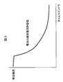
- FIG. 3 is a diagram illustrating an example of a relationship between a time window of an effective current of a general battery and an allowable value.
- the allowable value of the effective current of the battery varies depending on the time window for calculating the effective current. In other words, the longer the time window for calculating the effective current, the easier the battery will deteriorate during that time, so the allowable value needs to be set low.
- FIG. 4 is a diagram showing an example of the relationship between the number of battery use cycles and the degree of deterioration.
- a broken line in FIG. 4 during normal use where the effective current is less than or equal to the allowable value, the deterioration of the battery gradually proceeds as the number of use cycles of the battery increases.
- the internal resistance value temporarily rises with the increase in the number of battery use cycles, thereby deteriorating the battery. Appears to have advanced rapidly. In such a case, the battery performance cannot be fully exhibited.
- FIG. 5 is a diagram showing a control block of the assembled battery control unit 150 related to charge / discharge restriction.
- the assembled battery control unit 150 functionally includes control blocks of an effective current value calculation unit 151, an integrated time calculation unit 152, and a charge / discharge restriction unit 153 as a configuration for performing charge / discharge restriction of the assembled battery 110.
- the effective current value calculation unit 151 receives the current value of the charge / discharge current of the assembled battery 110 measured by the current detection unit 130.
- the effective current value calculation unit 151 calculates the effective current value of the charge / discharge current flowing in the assembled battery 110 based on the input current value. Details of the calculation method of the effective current value will be described later.
- the effective current value calculated by the effective current value calculation unit 151 is output to the integration time calculation unit 152 and the charge / discharge restriction unit 153.
- the integrated time calculation unit 152 compares the effective current value output from the effective current value calculation unit 151 with a predetermined allowable value, and obtains an integrated value (integrated time) of the time when the effective current value exceeds the allowable value.
- the accumulated time calculated by the accumulated time calculating unit 152 is output to the charge / discharge limiting unit 153.
- the charging / discharging limiting unit 153 should limit the charging / discharging current of the assembled battery 110 based on the effective current value output from the effective current value calculating unit 151 and the integrated time output from the integrated time calculating unit 152. Determine whether. If it is determined that the charge / discharge current should be limited, the allowable power value corresponding to the limited charge / discharge current is determined and output to the unit cell control units 121a and 121b and the vehicle control unit 200. Thereby, charging / discharging restrictions with respect to the assembled battery 110 are performed, and charging / discharging electric current is restrict
- the assembled battery control unit 150 can perform two-stage charge / discharge restriction on the assembled battery 110. Specifically, as the first stage charge / discharge restriction, charge / discharge restriction is performed when the effective current value exceeds a predetermined allowable value. Further, as the second stage charge / discharge restriction, further charge / discharge restriction is performed when the integrated value of the time when the effective current value exceeds the predetermined allowable value exceeds the predetermined threshold value.
- FIG. 6 is a flowchart of a process for performing the first stage charge / discharge restriction among the two stages of charge / discharge restrictions. The process shown in this flowchart is executed by the assembled battery control unit 150 at predetermined processing cycles.
- step S ⁇ b> 11 the assembled battery control unit 150 acquires a current measurement value from the current detection unit 130.
- current measurement values output from the current detection unit 130 at predetermined sampling intervals are acquired and stored.
- step S12 the assembled battery control unit 150 calculates the effective current value in the first time window by the effective current value calculation unit 151 based on the current measurement value acquired in step S11.
- the length of the first time window is 10 minutes
- the mean square value of each current measurement value obtained at every predetermined sampling interval in the latest ten minutes is obtained, and the square root of the mean square value is calculated.
- the effective current value in the first time window can be calculated.
- step S13 the assembled battery control unit 150 compares the effective current value calculated in step S12 with a predetermined first allowable value by the charge / discharge limiting unit 153.
- the first allowable value is set to 50A, and it is determined whether or not the effective current value in the first time window is larger than 50A.
- the process proceeds to step S14, and if larger than the first allowable value, the process proceeds to step S16.
- step S12 and S13 may be skipped and the process may proceed to the next step S14.
- step S14 the assembled battery control unit 150 uses the effective current value calculation unit 151 to calculate the effective current value in the second time window based on the current measurement value acquired in step S11.
- the second time window is measured in the same manner as in step S12 using each current measurement value acquired at predetermined sampling intervals in the most recent 1 hour.
- the effective current value in the window can be calculated.
- step S15 the assembled battery control unit 150 uses the charge / discharge limiting unit 153 to compare the effective current value calculated in step S14 with a predetermined second allowable value.
- the second allowable value is set to 30A, and it is determined whether or not the effective current value in the second time window is larger than 30A.
- the process of the flowchart of FIG. 6 is terminated, and if larger than the second allowable value, the process proceeds to step S16.
- steps S14 and S15 may be skipped and the flowchart of FIG. 6 may be terminated.
- step S ⁇ b> 16 the assembled battery control unit 150 performs charge / discharge restriction on the assembled battery 110 by the charge / discharge restriction unit 153. Specifically, an allowable power value corresponding to the limited charge / discharge current is determined, and the value is output to the cell control units 121a and 121b and the vehicle control unit 200, so that the battery pack 110 at the time of charge / discharge Control so that the input / output power is less than the allowable power. At this time, the limited charge / discharge current is preferably set to a value lower than the first allowable value and the second allowable value. If step S16 is performed, the assembled battery control part 150 will complete
- the first stage charge / discharge restriction can be performed on the assembled battery 110.
- the charge / discharge restriction is canceled because the determination results of steps S13 and S15 are both negative in the subsequent processes.
- FIG. 7 is a diagram showing an example of how the effective current changes due to the first stage charge / discharge restriction. As shown in FIG. 7, the effective current is relatively high until the time Ta when the assembled battery 110 is normally used without charge / discharge restriction, but the charge / discharge restriction of the first stage at the time Ta. After that, it can be seen that the effective current is suppressed to a low level thereafter.
- FIG. 8 is a flowchart of a process for performing the second stage charge / discharge restriction among the two stages of charge / discharge restrictions. The process shown in this flowchart is executed by the assembled battery control unit 150 at predetermined processing cycles.
- step S21 the assembled battery control unit 150 calculates an integrated time obtained by integrating the time when the effective current value exceeds the allowable value by the integrated time calculating unit 152.
- the accumulated time can be calculated by the method described below.
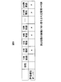
- FIG. 9 is a diagram for explaining a method of calculating the accumulated time.
- FIG. 9 shows, in a tabular form, an example of the determination result of step S15 of FIG. 6 performed every hour from 24 hours ago to the present when the second time window is one hour. .
- step S15 When the effective current value in the second time window exceeds the second allowable value, and therefore step S15 is affirmed, “x” is recorded in the corresponding column of the table of FIG. That is, the table of FIG. 9 shows that the effective current value exceeded the second allowable value in each time window of 2 hours, 4 hours, 5 hours, 23 hours, and 24 hours before the present. Show. When the vehicle system is stopped and the battery control system 120 is in a non-operating state, nothing is recorded in the corresponding column in the table of FIG.
- step S21 of FIG. 8 by counting the columns in which “x” is recorded in the table of FIG. 9, the accumulated time when the effective current value exceeds the allowable value can be calculated. That is, in the example shown in the table of FIG. 9, since the number of columns in which “x” is recorded is 5, the integrated time when the effective current value exceeds the allowable value can be obtained as 5 hours.
- the calculation method of the accumulated time as described above is merely an example, and other calculation methods may be used.
- the accumulated time can be calculated by recording the effective current value calculated in steps S12 and S14 in FIG. 6 and counting the number of those exceeding the allowable value and multiplying by the time window.
- step S ⁇ b> 22 the assembled battery control unit 150 sets the switching time as a threshold for the integrated time calculated in step S ⁇ b> 21 by the charge / discharge limiting unit 153.
- the switching time can be set as follows.
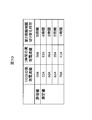
- FIG. 10 is a diagram for explaining a switching time setting method.
- the first time window and the second time window are 10 minutes and 1 hour, respectively
- an example of the relationship between the effective current value and the switching time in these time windows is shown in a table format. Show.
- the switching time used for the determination in step S22 of FIG. 8 is 5 hours. Can be set. Similarly, when each effective current value in the latest first and second time windows is less than 55A and 33A, the switching time can be set to 4 hours. For other effective current values, the switching time can be set according to the magnitude of the effective current value based on the table of FIG.
- the switching time setting method described above is merely an example, and other setting methods may be used.
- the switching time may be set based on effective current values in a plurality of past time windows instead of the latest effective current value.
- the switching time can also be set using only one of the effective current value in the first time window and the effective current value in the second time window.
- step S ⁇ b> 23 the assembled battery control unit 150 compares the integration time calculated in step S ⁇ b> 21 with the switching time set in step S ⁇ b> 22 by the charge / discharge limiting unit 153. As a result, if the accumulated time is longer than the switching time, the process proceeds to step S24, and if it is equal to or shorter than the switching time, the process proceeds to step S25.
- step S ⁇ b> 24 the assembled battery control unit 150 causes the charging / discharging limiting unit 153 to start limiting charging / discharging of the assembled battery 110.
- an allowable power value corresponding to the limited charge / discharge current is determined, and the value is output to the cell control units 121a and 121b and the vehicle control unit 200.
- the input / output power of the assembled battery 110 at the time of charging / discharging is controlled to be equal to or lower than the allowable power.
- the limited charge / discharge current is preferably lower than the limited charge / discharge current in step S16. If step S24 is performed, it will progress to step S25.
- the second stage charge / discharge restriction can be performed on the assembled battery 110. If step S24 has been executed in the process before the previous time and the second stage charge / discharge restriction is already being performed, the processes in steps S21 to S24 may be skipped.
- FIG. 11 is a diagram showing an example of how the effective current changes due to the charge / discharge restriction in the first stage and the second stage.
- the effective current is relatively high until time Tb when the assembled battery 110 is normally used without charge / discharge restriction, but the first stage charge / discharge restriction at time Tb. After that, it can be seen that the effective current is suppressed to a low level thereafter. Furthermore, when the second stage charge / discharge restriction is performed at the subsequent time Tc, it can be seen that the effective current is further suppressed to a lower level thereafter.
- the assembled battery control unit 150 calculates the elapsed time from the start of charge / discharge restriction in step S24 by the charge / discharge restriction unit 153.
- a timer built in the assembled battery control unit 150 can be used to calculate the elapsed time since the start of charge / discharge restriction.
- limiting may be acquired from the vehicle control part 200 of FIG. 1 by communication via the above-mentioned CAN, and elapsed time may be calculated based on this information. Note that when the vehicle system is stopped after the start of charge / discharge restriction and the battery control system 120 is in a non-operating state, it is preferable to calculate the elapsed time including that period.
- step S26 the assembled battery control unit 150 compares the elapsed time calculated in step S25 with a predetermined limit release time by the charge / discharge limiting unit 153.
- the restriction release time is set to 12 hours, and it is determined whether or not the elapsed time since the start of charge / discharge restriction in step S24 is longer than 12 hours. As a result, if the elapsed time from the start of charge / discharge restriction is equal to or less than the restriction release time (12 hours), the process of the flowchart of FIG. 8 is terminated, and if longer than the restriction release time, the process proceeds to step S27.
- step S27 the assembled battery control unit 150 releases the charge / discharge restriction on the assembled battery 110 started in step S24 by the charge / discharge restriction unit 153. Specifically, by outputting the allowable power value before starting the charge / discharge restriction in step S24 to the single battery control units 121a and 121b and the vehicle control unit 200, the input / output power of the assembled battery 110 at the time of charge / discharge is reduced. Control to return the allowable power to the original state. If step S27 is performed, the assembled battery control part 150 will complete
- the second stage charge / discharge restriction performed on the assembled battery 110 can be released. If the second stage charge / discharge restriction is not being implemented, the processing of steps S25 to S27 may be skipped.
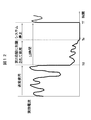
- FIG. 12 is a diagram showing an example of how the effective current changes due to the release of the charge / discharge restriction in the second stage.
- the effective current becomes 0 when the battery control system 120 is stopped at time Te. I understand that.
- the elapsed time from the time Td becomes 12 hours and the charge / discharge restriction is released, the effective current rises again.
- the battery control system 120 is connected to the assembled battery 110 and controls charging / discharging of the assembled battery 110.
- the battery control system 120 detects a current flowing through the assembled battery 110 and measures a current value, a voltage detecting unit 140 that detects a voltage of the assembled battery 110, and a temperature of the assembled battery 110.
- a temperature detection unit 125 and an assembled battery control unit 150 are provided.
- the assembled battery control unit 150 is calculated by the effective current value calculation unit 151 and the effective current value calculation unit 151 that calculate the effective current value in a predetermined time window based on the current value measured by the current detection unit 130. Based on the effective current value, it has functionally a charge / discharge limiter 153 that performs a first charge / discharge limit to limit the charge / discharge current.
- the effective current value calculation unit 151 calculates an effective current value in the first time window (step S12), and calculates an effective current value in a second time window different from the first time window ( In step S14), the effective current values in the two time windows are respectively calculated.
- the charge / discharge restriction unit 153 performs the first charge / discharge restriction based on these effective current values (steps S13, S15, and S16). Since it did in this way, the 1st charging / discharging restriction
- the assembled battery control unit 150 further includes an integrated time calculation unit 152 that calculates an integrated time that is an integrated value of the time when the effective current value exceeds a predetermined allowable value.
- the charging / discharging limiting unit 153 performs second charging / discharging limitation for further limiting the charging / discharging current based on the integrated time (step S21) calculated by the integrated time calculating unit 152 (steps S23, S24). .
- the charge / discharge restriction unit 153 sets a threshold value for the integration time according to the magnitude of the effective current value (step S22). This threshold value is compared with the accumulated time in step S23, and the second charge / discharge restriction is performed in step S24 based on the comparison result. Since it did in this way, according to the magnitude
- the charge / discharge restriction unit 153 releases the second charge / discharge restriction when the elapsed time since the start of the second charge / discharge restriction exceeds a predetermined restriction release time (steps S25 to S27). ). Since it did in this way, when 2nd charging / discharging restriction
- the battery control system 120 is connected to CAN which is a communication network in the vehicle.
- the charge / discharge limiting unit 153 can also acquire information on elapsed time via the CAN. In this way, even if the battery control system 120 does not have a timer function, the second charge / discharge restriction can be canceled at an appropriate timing.
- the effective current value calculation unit 151 is realized by the assembled battery control unit 150
- the integrated time calculation unit 152 and the charge / discharge restriction unit 153 are realized by the vehicle control unit 200.
- the assembled battery control unit 150 transmits information on the effective current value calculated by the effective current value calculation unit 151 to the vehicle control unit 200.
- the vehicle control unit 200 uses the information on the effective current value transmitted from the assembled battery control unit 150 to calculate the integration time when the effective current value exceeds the allowable value by the integration time calculation unit 152.
- the charge / discharge limiting unit 153 performs the first charge / discharge limit and the second charge / discharge limit. It is determined whether or not the restriction is performed, and the charge / discharge restriction is instructed to the battery control system 120 according to the determination result. Even if it does in this way, there can exist the above effects.
- the length of the time window for calculating the effective current value in the process for performing the charge / discharge restriction in the first stage, the allowable value for comparison with the calculated effective current value, and the like are examples. Other values may be used.
- the effective current value is calculated for two types of time windows. However, the effective current value is calculated only for one type of time window, and the processes of steps S14 and S15 in FIG. 6 are omitted. May be.
- the effective current value may be calculated for three or more types of time windows, and compared with an allowable value determined for each of the time windows, and it may be determined whether to perform charge / discharge restriction. For example, a time window having an arbitrary number and length between 10 seconds and 8 hours is selected, an effective current value is calculated for each time window, and the first stage is based on the comparison result with each allowable value.
- the charging / discharging limitation can be performed.
- the length of time for calculating the integration time in the process for performing the charge / discharge limitation in the second stage is an example, and other values may be used.
- whether the second stage charge / discharge restriction is canceled by calculating the elapsed time from the start of the second stage charge / discharge restriction and comparing this elapsed time with the restriction release time.
- Whether or not to cancel the second stage charge / discharge restriction by calculating the total time for performing the second stage charge / discharge restriction and comparing this total time with the restriction release time. It may be determined. In this case, when the vehicle system is stopped after the start of charge / discharge restriction and the battery control system 120 is in a non-operating state, it is preferable to calculate the total time excluding that period.
- each of the above-described configurations and functions can be realized in whole or in part as hardware using, for example, an integrated circuit, or can be realized as a program or software executed by a processor.
- Information such as programs and tables for realizing each function can be stored in a storage device such as a memory or a hard disk, or a storage medium such as an IC card or a DVD.
Abstract
Description
本発明の第2の態様によると、第1の態様の電池制御システムにおいて、実効電流値算出部は、互いに異なる複数のタイムウインドウにおける複数の実効電流値をそれぞれ算出し、充放電制限部は、複数の実効電流値に基づいて、第1の充放電制限を行うことが好ましい。
本発明の第3の態様によると、第1または第2の態様の電池制御システムは、実効電流値が所定の許容値を超えた時間の積算値である積算時間を算出する積算時間算出部をさらに備えてもよい。この電池制御システムにおいて、充放電制限部は、積算時間算出部により算出された積算時間に基づいて、充放電電流をさらに制限するための第2の充放電制限を行うことが好ましい。
本発明の第4の態様によると、第3の態様の電池制御システムにおいて、充放電制限部は、実効電流値の大きさに応じて積算時間に対するしきい値を設定し、積算時間としきい値の比較結果に基づいて、第2の充放電制限を行うことが好ましい。
本発明の第5の態様によると、第3または第4の態様の電池制御システムにおいて、充放電制限部は、第2の充放電制限を開始してからの経過時間または第2の充放電制限を行った合計時間が所定の制限解除時間を超えたときに、第2の充放電制限を解除することが好ましい。
本発明の第6の態様によると、第5の態様の電池制御システムは、車両内の通信ネットワークに接続されており、充放電制限部は、通信ネットワークを介して経過時間または合計時間の情報を取得することが好ましい。
本発明の第7の態様によると、車両制御システムは、電池と接続され、電池の充放電を制御する電池制御システムと、電池制御システムと接続された車両制御部と、を備え、電池制御システムは、電池に流れる充放電電流を検知して電流値を測定する電流検知部と、電池の電圧を検知する電圧検知部と、電池の温度を検知する温度検知部と、電流検知部により測定された電流値に基づいて所定のタイムウインドウにおける実効電流値を算出する実効電流値算出部と、を有し、車両制御部は、実効電流値算出部により算出された実効電流値に基づいて、充放電電流を制限するための第1の充放電制限を電池制御システムに対して指示する。
日本国特許出願2013年第166799号(2013年8月9日出願)
Claims (7)
- 電池と接続され、前記電池の充放電を制御する電池制御システムであって、
前記電池に流れる充放電電流を検知して電流値を測定する電流検知部と、
前記電池の電圧を検知する電圧検知部と、
前記電池の温度を検知する温度検知部と、
前記電流検知部により測定された電流値に基づいて、所定のタイムウインドウにおける実効電流値を算出する実効電流値算出部と、
前記実効電流値算出部により算出された実効電流値に基づいて、前記充放電電流を制限するための第1の充放電制限を行う充放電制限部と、を備える電池制御システム。 - 請求項1に記載の電池制御システムにおいて、
前記実効電流値算出部は、互いに異なる複数のタイムウインドウにおける複数の実効電流値をそれぞれ算出し、
前記充放電制限部は、前記複数の実効電流値に基づいて、前記第1の充放電制限を行う電池制御システム。 - 請求項1または2に記載の電池制御システムにおいて、
前記実効電流値が所定の許容値を超えた時間の積算値である積算時間を算出する積算時間算出部をさらに備え、
前記充放電制限部は、前記積算時間算出部により算出された積算時間に基づいて、前記充放電電流をさらに制限するための第2の充放電制限を行う電池制御システム。 - 請求項3に記載の電池制御システムにおいて、
前記充放電制限部は、前記実効電流値の大きさに応じて前記積算時間に対するしきい値を設定し、前記積算時間と前記しきい値の比較結果に基づいて、前記第2の充放電制限を行う電池制御システム。 - 請求項3または4に記載の電池制御システムにおいて、
前記充放電制限部は、前記第2の充放電制限を開始してからの経過時間または前記第2の充放電制限を行った合計時間が所定の制限解除時間を超えたときに、前記第2の充放電制限を解除する電池制御システム。 - 請求項5に記載の電池制御システムにおいて、
前記電池制御システムは、車両内の通信ネットワークに接続されており、
前記充放電制限部は、前記通信ネットワークを介して前記経過時間または前記合計時間の情報を取得する電池制御システム。 - 電池と接続され、前記電池の充放電を制御する電池制御システムと、
前記電池制御システムと接続された車両制御部と、を備え、
前記電池制御システムは、前記電池に流れる充放電電流を検知して電流値を測定する電流検知部と、前記電池の電圧を検知する電圧検知部と、前記電池の温度を検知する温度検知部と、前記電流検知部により測定された電流値に基づいて所定のタイムウインドウにおける実効電流値を算出する実効電流値算出部と、を有し、
前記車両制御部は、前記実効電流値算出部により算出された実効電流値に基づいて、前記充放電電流を制限するための第1の充放電制限を前記電池制御システムに対して指示する車両制御システム。
Priority Applications (7)
| Application Number | Priority Date | Filing Date | Title |
|---|---|---|---|
| CN201480044136.0A CN105453374B (zh) | 2013-08-09 | 2014-07-25 | 电池控制系统、车辆控制系统 |
| US14/910,277 US9931959B2 (en) | 2013-08-09 | 2014-07-25 | Battery control system and vehicle control system |
| JP2015530819A JP6171127B2 (ja) | 2013-08-09 | 2014-07-25 | 電池制御システム、車両制御システム |
| MYPI2016700255A MY184261A (en) | 2013-08-09 | 2014-07-25 | Battery control system and vehicle control system |
| MX2016001574A MX353626B (es) | 2013-08-09 | 2014-07-25 | Sistema de control de batería y sistema de control de vehículo. |
| EP14835101.8A EP3032690B1 (en) | 2013-08-09 | 2014-07-25 | Battery control system and vehicle control system |
| RU2016103959A RU2627239C1 (ru) | 2013-08-09 | 2014-07-25 | Система управления аккумуляторной батареей и система управления транспортным средством |
Applications Claiming Priority (2)
| Application Number | Priority Date | Filing Date | Title |
|---|---|---|---|
| JP2013166799 | 2013-08-09 | ||
| JP2013-166799 | 2013-08-09 |
Publications (1)
| Publication Number | Publication Date |
|---|---|
| WO2015019873A1 true WO2015019873A1 (ja) | 2015-02-12 |
Family
ID=52461212
Family Applications (1)
| Application Number | Title | Priority Date | Filing Date |
|---|---|---|---|
| PCT/JP2014/069731 WO2015019873A1 (ja) | 2013-08-09 | 2014-07-25 | 電池制御システム、車両制御システム |
Country Status (8)
| Country | Link |
|---|---|
| US (1) | US9931959B2 (ja) |
| EP (1) | EP3032690B1 (ja) |
| JP (1) | JP6171127B2 (ja) |
| CN (1) | CN105453374B (ja) |
| MX (1) | MX353626B (ja) |
| MY (1) | MY184261A (ja) |
| RU (1) | RU2627239C1 (ja) |
| WO (1) | WO2015019873A1 (ja) |
Cited By (2)
| Publication number | Priority date | Publication date | Assignee | Title |
|---|---|---|---|---|
| WO2017078017A1 (ja) * | 2015-11-02 | 2017-05-11 | 東海旅客鉄道株式会社 | 集電電流監視装置 |
| WO2018179854A1 (ja) * | 2017-03-30 | 2018-10-04 | 日立オートモティブシステムズ株式会社 | 電池エネルギー貯蔵システム、電池管理システムおよび制御方法 |
Families Citing this family (8)
| Publication number | Priority date | Publication date | Assignee | Title |
|---|---|---|---|---|
| JP2015154593A (ja) * | 2014-02-14 | 2015-08-24 | ソニー株式会社 | 充放電制御装置、電池パック、電子機器、電動車両および充放電制御方法 |
| JP6569122B2 (ja) * | 2015-08-05 | 2019-09-04 | 株式会社オートネットワーク技術研究所 | 車載充電システム |
| US10468730B2 (en) * | 2015-09-26 | 2019-11-05 | Intel Corporation | Battery reliability odometer |
| DE102018104711B4 (de) * | 2018-03-01 | 2021-09-09 | Einhell Germany Ag | Akkupack für ein Elektrogerät, Ladegerät für einen Akkupack und Verfahren zum Betreiben eines Akkupacks |
| US20210143662A1 (en) * | 2018-07-27 | 2021-05-13 | Hewlett-Packard Development Company, L.P. | Charging voltage reduction of batteries |
| CN110857034B (zh) * | 2018-08-21 | 2022-07-29 | 上海博泰悦臻网络技术服务有限公司 | 电动汽车的电池工作温度控制装置及方法 |
| JP7422670B2 (ja) * | 2018-09-27 | 2024-01-26 | 三洋電機株式会社 | 電源システム、及び管理装置 |
| CN110696680B (zh) * | 2019-09-17 | 2022-02-25 | 中国矿业大学 | 动力电池包温度预调控方法 |
Citations (7)
| Publication number | Priority date | Publication date | Assignee | Title |
|---|---|---|---|---|
| JP2008024124A (ja) * | 2006-07-20 | 2008-02-07 | Honda Motor Co Ltd | 車両用電源の制御装置およびその制御方法 |
| JP2009207312A (ja) * | 2008-02-28 | 2009-09-10 | Sanyo Electric Co Ltd | 車両用の電源装置とその電流制御方法 |
| JP2011229318A (ja) * | 2010-04-21 | 2011-11-10 | Makita Corp | 電動工具用バッテリの発熱量推定装置及び電動工具用装置 |
| JP2012044844A (ja) * | 2010-08-23 | 2012-03-01 | Mitsumi Electric Co Ltd | 保護回路 |
| JP2013027209A (ja) * | 2011-07-22 | 2013-02-04 | Panasonic Corp | 二次電池の保護システム |
| JP2013051115A (ja) | 2011-08-31 | 2013-03-14 | Toyota Motor Corp | 車両および車両の制御方法 |
| WO2013094057A1 (ja) * | 2011-12-22 | 2013-06-27 | 日立ビークルエナジー株式会社 | 電池制御装置、電池システム |
Family Cites Families (13)
| Publication number | Priority date | Publication date | Assignee | Title |
|---|---|---|---|---|
| US3617851A (en) | 1969-09-29 | 1971-11-02 | Christie Electric Corp | Battery charger with control circuit for cyclical charge and discharge as a function of battery voltage during discharge |
| CN100454712C (zh) * | 2000-10-03 | 2009-01-21 | 松下电器产业株式会社 | 功率生成控制系统和功率生成控制方法 |
| KR100906908B1 (ko) | 2006-12-11 | 2009-07-08 | 현대자동차주식회사 | 하이브리드 전기 차량의 배터리 충전량 제어 방법 |
| JP4987581B2 (ja) | 2007-06-15 | 2012-07-25 | 日立ビークルエナジー株式会社 | 電池制御装置 |
| WO2010079595A1 (ja) * | 2009-01-08 | 2010-07-15 | トヨタ自動車株式会社 | 非水電解液型二次電池システム及び車両 |
| US8004243B2 (en) * | 2009-04-08 | 2011-08-23 | Tesla Motors, Inc. | Battery capacity estimating method and apparatus |
| JP5496612B2 (ja) * | 2009-11-11 | 2014-05-21 | 三洋電機株式会社 | 電池の充放電可能電流演算方法及び電源装置並びにこれを備える車両 |
| JP5477778B2 (ja) * | 2010-05-28 | 2014-04-23 | スズキ株式会社 | 電池並列接続回路の制御装置 |
| JP5386443B2 (ja) * | 2010-06-30 | 2014-01-15 | 株式会社日立製作所 | 電源装置,鉄道車両 |
| JP5582397B2 (ja) | 2010-08-31 | 2014-09-03 | 日立工機株式会社 | 電動工具及び電動工具に用いられる電池パック |
| US8624559B2 (en) | 2010-10-14 | 2014-01-07 | GM Global Technology Operations LLC | Excessive current detection controls method |
| WO2012081696A1 (ja) * | 2010-12-16 | 2012-06-21 | 本田技研工業株式会社 | 電池制御装置および電池制御方法 |
| RU127521U1 (ru) | 2012-10-22 | 2013-04-27 | Федеральное государственное унитарное предприятие "18 Центральный научно-исследовательский институт" Министерства обороны Российской Федерации | Устройство контроля электрических параметров и управления режимом заряда литиевой аккумуляторной батареи |
-
2014
- 2014-07-25 MX MX2016001574A patent/MX353626B/es active IP Right Grant
- 2014-07-25 EP EP14835101.8A patent/EP3032690B1/en active Active
- 2014-07-25 MY MYPI2016700255A patent/MY184261A/en unknown
- 2014-07-25 RU RU2016103959A patent/RU2627239C1/ru active
- 2014-07-25 JP JP2015530819A patent/JP6171127B2/ja active Active
- 2014-07-25 CN CN201480044136.0A patent/CN105453374B/zh active Active
- 2014-07-25 US US14/910,277 patent/US9931959B2/en active Active
- 2014-07-25 WO PCT/JP2014/069731 patent/WO2015019873A1/ja active Application Filing
Patent Citations (7)
| Publication number | Priority date | Publication date | Assignee | Title |
|---|---|---|---|---|
| JP2008024124A (ja) * | 2006-07-20 | 2008-02-07 | Honda Motor Co Ltd | 車両用電源の制御装置およびその制御方法 |
| JP2009207312A (ja) * | 2008-02-28 | 2009-09-10 | Sanyo Electric Co Ltd | 車両用の電源装置とその電流制御方法 |
| JP2011229318A (ja) * | 2010-04-21 | 2011-11-10 | Makita Corp | 電動工具用バッテリの発熱量推定装置及び電動工具用装置 |
| JP2012044844A (ja) * | 2010-08-23 | 2012-03-01 | Mitsumi Electric Co Ltd | 保護回路 |
| JP2013027209A (ja) * | 2011-07-22 | 2013-02-04 | Panasonic Corp | 二次電池の保護システム |
| JP2013051115A (ja) | 2011-08-31 | 2013-03-14 | Toyota Motor Corp | 車両および車両の制御方法 |
| WO2013094057A1 (ja) * | 2011-12-22 | 2013-06-27 | 日立ビークルエナジー株式会社 | 電池制御装置、電池システム |
Non-Patent Citations (1)
| Title |
|---|
| See also references of EP3032690A4 |
Cited By (7)
| Publication number | Priority date | Publication date | Assignee | Title |
|---|---|---|---|---|
| WO2017078017A1 (ja) * | 2015-11-02 | 2017-05-11 | 東海旅客鉄道株式会社 | 集電電流監視装置 |
| US20180312064A1 (en) | 2015-11-02 | 2018-11-01 | Central Japan Railway Company | Collected-current monitoring device |
| US10377240B2 (en) | 2015-11-02 | 2019-08-13 | Central Japan Railway Company | Collected-current monitoring device |
| TWI685432B (zh) * | 2015-11-02 | 2020-02-21 | 日商東海旅客鐵道股份有限公司 | 集電電流監視裝置 |
| WO2018179854A1 (ja) * | 2017-03-30 | 2018-10-04 | 日立オートモティブシステムズ株式会社 | 電池エネルギー貯蔵システム、電池管理システムおよび制御方法 |
| JP2018170167A (ja) * | 2017-03-30 | 2018-11-01 | 日立オートモティブシステムズ株式会社 | 電池エネルギー貯蔵システム、電池管理システムおよび制御方法 |
| US11374425B2 (en) | 2017-03-30 | 2022-06-28 | Vehicle Energy Japan Inc. | Battery energy storage system, battery management system, and control method for controlling battery temperature |
Also Published As
| Publication number | Publication date |
|---|---|
| JP6171127B2 (ja) | 2017-08-02 |
| EP3032690B1 (en) | 2021-02-24 |
| EP3032690A1 (en) | 2016-06-15 |
| US20160185248A1 (en) | 2016-06-30 |
| CN105453374B (zh) | 2019-02-01 |
| MY184261A (en) | 2021-03-29 |
| EP3032690A4 (en) | 2017-03-29 |
| MX2016001574A (es) | 2016-05-02 |
| MX353626B (es) | 2018-01-09 |
| RU2627239C1 (ru) | 2017-08-04 |
| JPWO2015019873A1 (ja) | 2017-03-02 |
| US9931959B2 (en) | 2018-04-03 |
| CN105453374A (zh) | 2016-03-30 |
Similar Documents
| Publication | Publication Date | Title |
|---|---|---|
| JP6171127B2 (ja) | 電池制御システム、車両制御システム | |
| JP6233856B2 (ja) | 電池制御システム、車両制御システム | |
| JP6119402B2 (ja) | 内部抵抗推定装置及び内部抵抗推定方法 | |
| JP6171128B2 (ja) | 電池制御システム、車両制御システム | |
| JP6084225B2 (ja) | 電池制御装置、二次電池システム | |
| JP6129306B2 (ja) | 電池制御装置 | |
| US20140184236A1 (en) | Battery control apparatus and battery system | |
| JP5670556B2 (ja) | 電池制御装置 | |
| JP6171132B2 (ja) | 電池制御システム、車両制御システム | |
| WO2008065910A1 (en) | Accumulator failure detecting device, accumulator failure detecting method, accumulator failure detecting program, and computer-readable recording medium containing the accumulator failure detecting program | |
| JP2009081981A (ja) | 充電状態最適化装置及びこれを具えた組電池システム | |
| WO2017056732A1 (ja) | 電池制御装置及び電池システム | |
| JP7131290B2 (ja) | 表示装置およびそれを備える車両 | |
| US20140210483A1 (en) | Processing device for battery pack and processing method therefor | |
| GB2533519A (en) | Method for minimizing cell aging of a battery and/or battery comprising an apparatus for minimizing cell aging of the battery | |
| JP2018125965A (ja) | 蓄電装置および蓄電制御方法 | |
| JP5851514B2 (ja) | 電池制御装置、二次電池システム | |
| JP6332273B2 (ja) | 蓄電システム、蓄電池の制御方法及びプログラム | |
| JPWO2017022251A1 (ja) | 二次電池の充放電装置、二次電池を用いた蓄電システム、二次電池の充放電方法、および二次電池の充放電プログラムが格納された非一時的なコンピュータ可読媒体 | |
| JPWO2012169061A1 (ja) | 電池制御装置、電池システム |
Legal Events
| Date | Code | Title | Description |
|---|---|---|---|
| WWE | Wipo information: entry into national phase |
Ref document number: 201480044136.0 Country of ref document: CN |
|
| 121 | Ep: the epo has been informed by wipo that ep was designated in this application |
Ref document number: 14835101 Country of ref document: EP Kind code of ref document: A1 |
|
| DPE2 | Request for preliminary examination filed before expiration of 19th month from priority date (pct application filed from 20040101) | ||
| WWE | Wipo information: entry into national phase |
Ref document number: 2014835101 Country of ref document: EP |
|
| WWE | Wipo information: entry into national phase |
Ref document number: MX/A/2016/001574 Country of ref document: MX |
|
| ENP | Entry into the national phase |
Ref document number: 2015530819 Country of ref document: JP Kind code of ref document: A |
|
| WWE | Wipo information: entry into national phase |
Ref document number: 14910277 Country of ref document: US Ref document number: IDP00201600812 Country of ref document: ID |
|
| NENP | Non-entry into the national phase |
Ref country code: DE |
|
| ENP | Entry into the national phase |
Ref document number: 2016103959 Country of ref document: RU Kind code of ref document: A |