WO2015019695A1 - 気腹装置 - Google Patents
気腹装置 Download PDFInfo
- Publication number
- WO2015019695A1 WO2015019695A1 PCT/JP2014/064938 JP2014064938W WO2015019695A1 WO 2015019695 A1 WO2015019695 A1 WO 2015019695A1 JP 2014064938 W JP2014064938 W JP 2014064938W WO 2015019695 A1 WO2015019695 A1 WO 2015019695A1
- Authority
- WO
- WIPO (PCT)
- Prior art keywords
- suction
- air supply
- predetermined gas
- pipe
- flow rate
- Prior art date
Links
Images


Classifications
-
- A—HUMAN NECESSITIES
- A61—MEDICAL OR VETERINARY SCIENCE; HYGIENE
- A61M—DEVICES FOR INTRODUCING MEDIA INTO, OR ONTO, THE BODY; DEVICES FOR TRANSDUCING BODY MEDIA OR FOR TAKING MEDIA FROM THE BODY; DEVICES FOR PRODUCING OR ENDING SLEEP OR STUPOR
- A61M13/00—Insufflators for therapeutic or disinfectant purposes, i.e. devices for blowing a gas, powder or vapour into the body
- A61M13/003—Blowing gases other than for carrying powders, e.g. for inflating, dilating or rinsing
- A61M13/006—Blowing gases other than for carrying powders, e.g. for inflating, dilating or rinsing with gas recirculation
-
- A—HUMAN NECESSITIES
- A61—MEDICAL OR VETERINARY SCIENCE; HYGIENE
- A61B—DIAGNOSIS; SURGERY; IDENTIFICATION
- A61B1/00—Instruments for performing medical examinations of the interior of cavities or tubes of the body by visual or photographical inspection, e.g. endoscopes; Illuminating arrangements therefor
- A61B1/012—Instruments for performing medical examinations of the interior of cavities or tubes of the body by visual or photographical inspection, e.g. endoscopes; Illuminating arrangements therefor characterised by internal passages or accessories therefor
- A61B1/015—Control of fluid supply or evacuation
-
- A—HUMAN NECESSITIES
- A61—MEDICAL OR VETERINARY SCIENCE; HYGIENE
- A61B—DIAGNOSIS; SURGERY; IDENTIFICATION
- A61B1/00—Instruments for performing medical examinations of the interior of cavities or tubes of the body by visual or photographical inspection, e.g. endoscopes; Illuminating arrangements therefor
- A61B1/313—Instruments for performing medical examinations of the interior of cavities or tubes of the body by visual or photographical inspection, e.g. endoscopes; Illuminating arrangements therefor for introducing through surgical openings, e.g. laparoscopes
- A61B1/3132—Instruments for performing medical examinations of the interior of cavities or tubes of the body by visual or photographical inspection, e.g. endoscopes; Illuminating arrangements therefor for introducing through surgical openings, e.g. laparoscopes for laparoscopy
-
- A—HUMAN NECESSITIES
- A61—MEDICAL OR VETERINARY SCIENCE; HYGIENE
- A61M—DEVICES FOR INTRODUCING MEDIA INTO, OR ONTO, THE BODY; DEVICES FOR TRANSDUCING BODY MEDIA OR FOR TAKING MEDIA FROM THE BODY; DEVICES FOR PRODUCING OR ENDING SLEEP OR STUPOR
- A61M2202/00—Special media to be introduced, removed or treated
- A61M2202/02—Gases
- A61M2202/0225—Carbon oxides, e.g. Carbon dioxide
-
- A—HUMAN NECESSITIES
- A61—MEDICAL OR VETERINARY SCIENCE; HYGIENE
- A61M—DEVICES FOR INTRODUCING MEDIA INTO, OR ONTO, THE BODY; DEVICES FOR TRANSDUCING BODY MEDIA OR FOR TAKING MEDIA FROM THE BODY; DEVICES FOR PRODUCING OR ENDING SLEEP OR STUPOR
- A61M2205/00—General characteristics of the apparatus
- A61M2205/33—Controlling, regulating or measuring
- A61M2205/3331—Pressure; Flow
- A61M2205/3334—Measuring or controlling the flow rate
-
- A—HUMAN NECESSITIES
- A61—MEDICAL OR VETERINARY SCIENCE; HYGIENE
- A61M—DEVICES FOR INTRODUCING MEDIA INTO, OR ONTO, THE BODY; DEVICES FOR TRANSDUCING BODY MEDIA OR FOR TAKING MEDIA FROM THE BODY; DEVICES FOR PRODUCING OR ENDING SLEEP OR STUPOR
- A61M2205/00—General characteristics of the apparatus
- A61M2205/33—Controlling, regulating or measuring
- A61M2205/3331—Pressure; Flow
- A61M2205/3344—Measuring or controlling pressure at the body treatment site
-
- A—HUMAN NECESSITIES
- A61—MEDICAL OR VETERINARY SCIENCE; HYGIENE
- A61M—DEVICES FOR INTRODUCING MEDIA INTO, OR ONTO, THE BODY; DEVICES FOR TRANSDUCING BODY MEDIA OR FOR TAKING MEDIA FROM THE BODY; DEVICES FOR PRODUCING OR ENDING SLEEP OR STUPOR
- A61M2205/00—General characteristics of the apparatus
- A61M2205/75—General characteristics of the apparatus with filters
-
- A—HUMAN NECESSITIES
- A61—MEDICAL OR VETERINARY SCIENCE; HYGIENE
- A61M—DEVICES FOR INTRODUCING MEDIA INTO, OR ONTO, THE BODY; DEVICES FOR TRANSDUCING BODY MEDIA OR FOR TAKING MEDIA FROM THE BODY; DEVICES FOR PRODUCING OR ENDING SLEEP OR STUPOR
- A61M2210/00—Anatomical parts of the body
- A61M2210/10—Trunk
- A61M2210/1017—Peritoneal cavity
Definitions
- the present invention relates to an insufflation apparatus for insufflation in a body cavity.
- a pneumoperitoneum is used to send a predetermined gas, such as carbon dioxide, into the abdominal cavity to ensure an observation field of view using a laparoscope and a region for operation.
- a predetermined gas such as carbon dioxide
- the smoke generated in the abdominal cavity is aspirated by the suction device in order to prevent observation due to smoke generated in the abdominal cavity. Exhaust smoke outside.
- the pressure of gas in the abdominal cavity decreases due to suction, it is necessary to supply new carbon dioxide gas from a cylinder serving as an air supply source, and there is a disadvantage that consumption of carbon dioxide gas increases.
- Japanese Patent Publication No. 2013-505812 as a conventional example for eliminating the disadvantage of increasing the consumption of carbon dioxide gas in this way, the suctioned carbon dioxide gas is not released to the atmosphere, but in a device having a filter.
- a configuration is disclosed in which gas is circulated by a fluid pump and the gas from which smoke has been removed by a filter is returned to the abdominal cavity again.
- the above conventional example is configured to circulate and reuse the carbon dioxide gas as the sucked predetermined gas, so that the consumption of the carbon dioxide gas can be reduced, but when the generation of smoke in the abdominal cavity becomes large. Can not respond. For this reason, an insufflation apparatus that can cope with a case where a large amount of smoke is generated in the abdominal cavity is desired.
- the present invention has been made in view of the above points, and can be used in an operation mode in which a predetermined gas is circulated and reused, and an operation mode corresponding to a case where a large amount of smoke is generated in the abdominal cavity.
- an object is to provide an insufflation apparatus that can be used.
- An insufflation apparatus connects an air supply source connection unit connected to an air supply source for supplying a predetermined gas and an air supply line for supplying the predetermined gas to a subject.
- An air supply line connection part for connecting the air supply source connection part and the air supply line connection part, and a suction line for aspirating the predetermined gas from within the subject.
- An aspiration line connection part for connection, a pump for circulating the predetermined gas to the subject, a circulation line for connecting the aspiration line connection part and the pump, and the pump A connection pipe line connecting the first pipe line, a suction source connection part connecting the suction source for sucking the predetermined gas, the suction source connection part and the circulation pipe line Second pipe to be connected, and a state in which the predetermined gas sucked from the suction pipe connecting portion flows through the second pipe
- a switching unit that selectively switches between a state of flowing through the first conduit through the pump, a first operation mode for circulating the predetermined gas to the subject through the pump, and the predetermined And a control unit that controls the switching unit so as to operate in a second operation mode in which the gas is sucked to the suction source side through the second conduit.
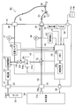
- FIG. 1 is a diagram showing an overall configuration of an endoscopic surgery system including an insufflation apparatus according to a first embodiment of the present invention.
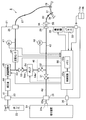
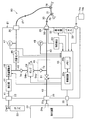
- FIG. 2A is a diagram showing an overall configuration of the pneumoperitoneum according to the first embodiment of the present invention.
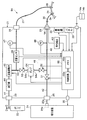
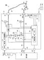
- FIG. 2B is a diagram showing an overall configuration of an insufflation apparatus according to a first modified example of the first embodiment of the present invention.
- FIG. 3 is a view showing the structure near the suction cap receiver, the structure of the filter, and the like in the case of the first modification.
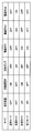
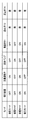
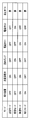
- FIG. 4 is a diagram showing, in a tabular form, various operation modes in the first embodiment and operation states of devices constituting an insufflation apparatus such as a suction device and a flow rate adjustment valve related to the operation modes.
- FIG. 1 is a diagram showing an overall configuration of an endoscopic surgery system including an insufflation apparatus according to a first embodiment of the present invention.
- FIG. 2A is a diagram showing an overall configuration of the pneumo
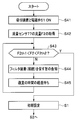
- FIG. 5 is a flowchart showing the processing contents of a typical operation in the first embodiment.
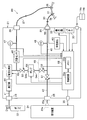
- FIG. 6 is a diagram showing a configuration of an insufflation apparatus according to a second modification of the first embodiment of the present invention.
- FIG. 7 is a diagram showing a configuration of an insufflation apparatus according to a third modification of the first embodiment of the present invention.
- FIG. 8 is a diagram showing, in a tabular form, operation states of devices related to each operation mode in the case of the third modification.
- FIG. 9 is a diagram showing a configuration of an insufflation apparatus according to a fourth modified example of the first embodiment of the present invention.
- FIG. 10 is a diagram showing, in a tabular form, operation states of devices related to each operation mode in the case of the fourth modified example.
- FIG. 11 is a diagram showing an overall configuration of an insufflation apparatus according to the second embodiment of the present invention.
- FIG. 12 is a view showing the structure near the suction cap receiver and the structure of the filter in the second embodiment.
- FIG. 13 is a diagram showing, in a tabular form, operation states of devices related to each operation mode in the second embodiment.
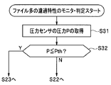
- FIG. 14A is a flowchart showing processing for monitoring and determining the filtration characteristics of a filter.
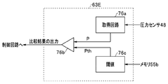
- FIG. 14B is a diagram illustrating a configuration of a characteristic determination circuit that determines the filtration characteristics of the filter.
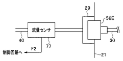
- FIG. 14C is a diagram showing a configuration for monitoring and determining the filtration characteristics of a filter using a flow sensor.
- FIG. 15 is a flowchart showing the processing contents for detecting the attachment (connection) of a filter using a flow sensor.
- FIG. 16 is an explanatory diagram of a configuration for detecting attachment (connection) of a filter different from that in FIG. 15.
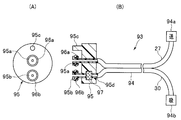
- FIG. 17 is an explanatory diagram of a configuration of a connector receiver in the apparatus main body.
- 18 is an explanatory view of the configuration of an air supply and suction tube device that is detachably connected to the connector receiver of FIG.
- FIG. 19 is a diagram showing a cross-sectional structure of an air supply & suction tube.
- FIG. 20 is an explanatory diagram of a configuration of an air supply & suction tube device having a structure different from that of FIG. FIG.
- FIG. 21 is a view showing a tube connector having a shape different from that in FIG.
- FIG. 22 is an explanatory diagram in which a filter in the tube connector of FIG. 18 is arranged outside.
- FIG. 23 is a diagram showing an overall configuration of an insufflation apparatus according to a modification of the second embodiment of the present invention.
- an endoscopic operation system 1 includes an electric scalpel device 4 as a surgical operation device for performing an operation on a patient 3 as a subject placed on a bed 2, and an internal surgical operation.
- An endoscope apparatus 6 for observing using the endoscope 5 and a first gastro stomach in the abdomen 3a to be operated in order to secure a field of view by the endoscope 5 and a region to be operated by the electric knife 7.
- the insufflation apparatus 8 according to the embodiment is provided.
- the abdomen 3a may be defined to form the subject.
- the electric knife device 4 includes an electric knife power supply device 11 that generates high-frequency power, and an electric knife 7 to which the high-frequency power generated by the electric knife power supply device 11 is supplied via a cable 12.
- an electric knife 7 By operating a switch provided on the gripping portion of the electric knife 7, a high-frequency current can be applied to the affected area gripped by, for example, a bipolar electrode at the tip of the electric knife 7, and treatment such as cauterization can be performed.
- the electric knife 7 is inserted into the abdomen 3a by a trocar (not shown).
- the endoscope device 6 is inserted into the abdomen 3 a via the first trocar 28 (with the endoscope camera 15 mounted), and a light source that supplies illumination light to the endoscope 5.
- a video processor 16 as a signal processing device that performs signal processing on the device 34, an endoscope camera 15 that houses an imaging device mounted on an eyepiece of the endoscope 5, and a video signal generated by the video processor 16 It has a monitor 17 as an endoscopic image display device that displays an endoscopic image captured by the imaging device in the endoscopic camera 15 by being input.
- the light source device 34 supplies (transmits) the illumination light generated by the light source device to the endoscope 5 via the light guide cable 18.
- the illumination light supplied via the light guide cable 18 is transmitted via a light guide (not shown) in the insertion portion 19 of the endoscope 5 and is emitted to the outside from an illumination window (not shown) at the tip of the insertion portion 19.
- the affected part in the abdominal part 3a is illuminated.
- An illuminated subject such as an affected part is imaged as an optical image by an objective lens provided in the observation window, and the optical image is transmitted to the eyepiece, captured by an imaging device in the endoscope camera 15, and subjected to photoelectric conversion. Is done.
- An imaging signal imaged by the imaging device is input to the video processor 16 via the imaging cable 20. Then, after the video processor 16 performs signal processing on the imaging signal, an endoscopic image is displayed on the monitor 17. Note that, instead of the endoscope 5 to which the endoscope camera 15 is attached, an endoscope in which an imaging element is built in the distal end portion of the insertion portion 19 may be used.
- An insufflation apparatus main body 21 covered with a housing constituting the insufflation apparatus 8 supplies (supplies) carbon dioxide gas as a predetermined gas for inhaling the abdomen 3a. It has a connection cap receiver 23 as an air supply source connection for connecting to a carbon dioxide gas cylinder (simply abbreviated as gas cylinder or cylinder) 22 containing carbon dioxide gas as an air source (or supply source) in a high pressure state.
- the apparatus main body 21 is connected to the gas cylinder 22 via a connection pipe connected to the connection cap receiver 23.
- the apparatus main body 21 has a connection base receiver 25 as a suction source connection part for connecting to a suction device 24 as a suction source for sucking carbon dioxide gas as a predetermined gas.
- the apparatus main body 21 is connected to the suction cap receiver 24 a of the suction device 24 via a connection pipe 25 a connected to the connection cap receiver 25.
- the suction device 24 includes a fluid pump having a suction capacity larger than that of a fluid pump 54 provided in the device main body, which will be described later.
- the apparatus main body 21 adjusts the carbon dioxide gas from the gas cylinder 22 to an appropriate flow rate suitable for air supply, and then one end of the apparatus main body 21 is connected to the air supply base receiver 26 from the air supply base receiver 26 as an air supply pipe line connecting portion. Air is supplied to the first trocar 28 side as an air supply trocar to which the other end of the air supply tube 27 is connected via a flexible air supply tube 27 constituting the air supply pipe line Can do.
- the first trocar 28 is inserted into the abdomen 3 a, and the hollow portion of the air supply tube 27 communicates with the inside of the abdomen 3 a, that is, the abdominal cavity via the first trocar 28. Then, in the air supply mode to be described later, carbon dioxide gas is supplied to the first trocar 28 side through the air supply tube 27 connected to the air supply base 26, whereby the abdominal cavity of the patient 3 is gasified with carbon dioxide gas. I can be hungry. Further, the apparatus main body 21 is provided with a suction cap receiver 29 as a suction pipe connection portion so that the smoke generated when the pressure in the abdominal cavity is lowered or the electric scalpel 7 is used can be sucked and removed. And a second trocar as a suction trocar to which the other end of the suction tube 30 is connected via a suction tube 30 having flexibility constituting the suction pipe line. 31 is connected.
- the second trocar 31 is inserted into the abdomen 3 a, and the hollow portion of the suction tube 30 communicates with the inside of the abdomen 3 a, that is, the abdominal cavity via the second trocar 31. Then, carbon dioxide in the abdominal cavity can be sucked into the apparatus main body 21 through the suction tube 30 in a circulation mode described later.
- an operation panel 32 (simply abbreviated as “panel” in the drawing) for performing various operations and settings and a display 33 for displaying the pressure in the abdominal cavity, the air flow rate, and the like are provided on the front surface of the apparatus main body 21. It is provided.
- the device main body 21 has a foot switch 14a, 14b that performs an instruction operation of air supply, suction, or smoke removal by an operation that a user such as an operator steps on with a foot, and a suction device 24 is turned on.
- the communication cable 35 which sends the signal which performs / OFF is provided.
- the insufflation apparatus 8 may be defined as an apparatus provided with an air supply tube 27 and a suction tube 30 connected to the apparatus main body 21 in addition to the apparatus main body 21, or an air supply source and a suction source. It may be defined including
- FIG. 2A shows the internal configuration of the apparatus main body 21 and the overall configuration of the pneumoperitoneum 8.
- the connection base receiver 23 and the air supply base receiver 26 provided on the outer surface of the casing are connected by an air supply pipe 41 as a first pipe provided in the casing.
- the suction cap receiver 29 and the connection cap receiver 25 provided on the outer surface of the casing serve as a circulation pipe 40 provided inside the casing and a second pipe provided with a switching unit 49 in the middle.
- the suction pipe line 42 Further, the air supply line 41 and the circulation line 40 are connected via a fluid pump 54 to which an end of the circulation line 40 is connected and a connection line 43 as a third line. Is done.
- a pressure reducing device 44 for reducing pressure, a flow rate adjusting valve 45 for adjusting a flow rate (constituting a flow rate variable unit), a flow rate sensor 46 as a sensor for detecting a flow rate, and a pressure are measured in the air supply line 41.
- the first pressure sensor 47 is arranged in the order close to the connection cap receiver 23.
- a second pressure sensor 48 for measuring pressure is disposed on the circulation pipe 40, and a first electromagnetic valve constituting a switching unit 49 is provided on the suction pipe 42 constituting the second pipe. 51 is arranged.
- a second electromagnetic valve 52 constituting a switching unit 49 is inserted in the circulation pipe 40 in the middle, and an end thereof is a fluid pump (simply abbreviated as “pump” in the drawings such as FIG. 2A) 54.
- the discharge port 54b of the fluid pump 54 is connected to one end of the connection line 43, and a third electromagnetic valve 53 is disposed in the middle of the connection line 43.
- the fluid pump 54 incorporates a motor and the like, sucks fluid from the suction port 54a (in this case, gas such as carbon dioxide), discharges the fluid sucked from the discharge port 54b, and flows it to the connection line 43 side. .
- connection pipe 43 connects the fluid pump 54 and the air supply pipe line 41 forming the first pipe line.
- the second pressure sensor 48 is provided on the circulation conduit 40 at a position closer to the suction cap receiver 29 than the switching unit 49.
- the first solenoid valve 51 is provided on the suction conduit 42 that is closer to the connection cap receiver 25 than the circulation conduit 40.
- control board 55 that electrically controls the operation of the flow rate adjusting valve 45, the first electromagnetic valve 51, the second electromagnetic valve 52, the third electromagnetic valve 53, and the fluid pump 54. It is provided.
- the control board 55 includes a central processing unit (abbreviated as CPU) and the like, and stores a control circuit 55a for controlling the operation of the flow rate adjusting valve 45 and the like, and program data for the CPU to perform a predetermined control operation. And a memory 55b for storing various control data and the like.
- the control circuit 55 a of the control board 55 has a flow rate detection value measured by the flow sensor 46, a pressure value measured by the first pressure sensor 47 and the second pressure sensor 48, and an operation of the operation panel 32.
- the suction cap receiver 29 receives clean carbon dioxide gas by preventing the passage of fine particles other than carbon dioxide, such as smoke mixed in the carbon dioxide sucked from the second trocar 31 side.
- a suction base 36 provided with a filter 56 formed of fibers or the like having a fine mesh structure so as to pass through is provided near the end of the suction tube 30 is detachably attached.
- the suction base 36 provided with a filter 56 in the middle of the suction tube 30 is detachably connected to the suction base receiver 29 of the apparatus main body 21.
- a configuration in which the filter 56 can be detachably connected to the suction cap receiver 29 as in the configuration of the first modification shown in FIG. 2B may be adopted.
- the insufflation apparatus 8A of the first modified example shown in FIG. 2B is the same as the insufflation apparatus 8 of the first embodiment, provided with a filter mounting portion in the suction cap receiver 29 in the apparatus main body 21 of the first embodiment.
- the part provided with the characteristic detection circuit 63 in the main body 21 is different.
- the suction cap receiver 29 includes a filter mounting portion that detachably mounts (connects) the filter 56.
- the filter mounting portion is not limited to the configuration shown in FIG. 3 and can be configured as shown in FIGS. Since the filter 56 is for filtering carbon dioxide sucked from the abdominal cavity into clean carbon dioxide, the position where the filter 56 is disposed is from the middle of the suction tube 30 to the circulation conduit 40. Or any position up to the solenoid valve 53 or the check valve 74 described later on the connection line 43 connected to the circulation line 40.
- the filter 56 filters a predetermined gas flowing through the suction tube 30 serving as a suction conduit from at least the patient 3 forming the subject.
- the filter 56 needs to be replaced, when it is provided on the apparatus main body 21 side, the position of the suction cap receiver 29 that is an easily replaceable position becomes a dominant position (place). Since the suction tube 30 is used in a disposable manner, a filter may be integrally provided on the suction tube 30 side as in the case of the first embodiment shown in FIG. In this case, the filter 56 may be structured as shown in FIG.
- FIG. 18 shows a structure in the vicinity of the suction cap receiver 29 in the first modification of the first embodiment.
- 3A is a cross-sectional view of the suction cap receiver 29 cut along a plane perpendicular to the central axis of the circulation conduit 40
- FIG. 3B is a side view seen from the right side of FIG. 3A.
- FIG. 3C is a cross-sectional view of the filter 56
- FIG. 3D is a cross-sectional view of the state in which the filter 56 is mounted in the concave portion of the suction cap receiver 29.
- the suction cap receiver 29 includes a ring-shaped first step portion 61a at the end of the circulation conduit 40 and a ring formed on the outer peripheral side of the first step portion 61a.
- a light emitting diode (LED) 62a is arranged along the ring shape on the second stepped portion 61b, and a solar cell or the like is arranged along the ring shape on the first stepped portion 61a.
- the light receiving element 62b is arranged.
- the LED 62a emits light when supplied with LED power from the control board 55.
- the LED 62a emits light in a direction substantially parallel to the central axis of the circulation conduit 40, and the light receiving element 62b is also a direction substantially parallel to the central axis of the circulation conduit 40 (however, the direction opposite to the emission direction). It has a directional characteristic to receive light from.
- the filter 56 shown in FIG. 3C is detachably attached to the suction base 29 having the two-stage recess.
- the filter 56 shown in FIG. 3C has, for example, a two-layer disk-shaped filter disc 56b as a spacer in a filter case 56a fitted to the second stepped portion 61b.
- An attachment base 56c is provided in the center of one surface of the filter case 56a and is fitted to the circulation conduit 40 and is attached to the end of the suction tube 30 in the center of the other surface.
- a suction tube attachment portion 56d for connecting a connection base provided in the portion is provided.
- a ring-shaped mirror 56e is provided between the two adjacent filter disks 56b. As shown in FIG. 3D, the mirror 56e reflects light that has passed through the filter disk 56b from the LED 62a toward the light receiving element 62b.
- the filter disc 56b has a characteristic of transmitting the light of the LED 62a at a predetermined rate. When the amount of fine particles such as smoke adhering to the meshes constituting the filter disk 56b increases, the filtering characteristics deteriorate and the output level of the light receiving element 62b decreases.
- means for notifying the replacement of the filter 56 when the filtration characteristics deteriorate as follows. .
- the detection signal of the light receiving element 62b is input to the characteristic detection circuit 63.
- the characteristic detection circuit 63 determines the output signal level of the light receiving element 62b (in this case, the electromotive force according to the amount of received light) and the threshold value Vth.
- the comparator 63a to be compared is included and the output signal level is equal to or higher than the threshold, it is determined that the filter disk 56b is in a usable state that does not require replacement, and the output signal level is lower than the threshold
- the determination signal indicating that the filtering function of the filter disk 56b or the filter 56 is lowered is output to the control board 55 (the control circuit 55a).
- the control circuit 55a When the control circuit 55a receives the determination signal indicating that the filtration function has deteriorated, the control circuit 55a controls the display device 33 to display notification information for urging the filter disk 56b or the filter 56 to be replaced. For this reason, the display device 33 forms a notification unit that notifies a user such as a surgeon who performs the surgery that the filtration function of the filter 56 is reduced and prompts replacement.
- the control circuit 55a as the control means is configured so that the insufflation apparatus 8 performs the insufflation operation in four types of operation modes as shown in FIG.
- the suction device 24, the flow rate adjusting valve 45, the fluid pump 54, the first to third electromagnetic valves 51 to 53, and the like are controlled. Therefore, the control circuit 55a has a function of an operation mode control unit that controls a plurality of types of operation modes. In the four types of operation modes, at least the fluid pump 54 is operated, and the carbon dioxide gas (as a predetermined gas) filtered by the filter 56 is passed through the air supply tube 27 (as the air supply line) through the first trocar 31.
- the first operation mode (in other words, the circulation mode) for supplying air to circulate to the (or subject) side, and the operation of the fluid pump 54 are stopped, and the carbon dioxide gas filtered by the filter 56 is aspirated as a suction source.
- a second operation mode in other words, smoke emission mode in which the device 24 sucks and discharges.
- the control circuit 55a turns off the first to third solenoid valves 51 to 53, it means that the solenoid valves are closed.
- the control circuit 55a turns off the suction device 24, the flow rate adjustment valve 45, and the first electromagnetic valve 51, and turns on the fluid pump 54, the second and third electromagnetic valves 52 and 53. Turn it on.
- control circuit 55a performs control so that ON and OFF in the circulation mode are switched. Specifically, the control circuit 55a turns on the suction device 24, the flow rate adjustment valve 45, and the first electromagnetic valve 51, and turns off the fluid pump 54, the second and third electromagnetic valves 52 and 53.
- the control circuit 55a controls to turn off the flow rate adjusting valve in the smoke exhaust mode. Specifically, the control circuit 55a turns on the suction device 24 and the first electromagnetic valve 51, and turns off the flow rate adjustment valve 45, the fluid pump 54, and the second and third electromagnetic valves 52 and 53.
- 2B illustrates a configuration in which the characteristic detection circuit 63 is provided outside the control board 55, the characteristic detection circuit 63 may be provided inside the control board 55.
- 1, 2 ⁇ / b> A, and 2 ⁇ / b> B show the configuration in which the connection tube 25 a connected to the connection cap receiver 25 of the apparatus main body 21 is connected to the suction device 24 that is a suction source. It may be configured to be connected to a suction device provided outside.
- the insufflation apparatus 8 of the present embodiment includes a connection cap receiver 23 as an air supply source connection unit for connecting to a gas cylinder 22 as an air supply source for supplying, for example, carbon dioxide as a predetermined gas, and a subject.
- An air supply base 26 as an air supply line connection part for connecting an air supply tube 27 as an air supply line for supplying the predetermined gas to the patient 3 (abdominal part 3a) constituting the air supply, and the air supply
- An air supply conduit 41 as a first conduit connecting a source connection portion and the air supply conduit connection portion, and an aspiration tube 30 as an aspiration conduit for aspirating the predetermined gas from within the subject
- An aspiration cap receiver 29 as an aspiration line connection part for connection, a fluid pump 54 as a pump for circulating the predetermined gas to the subject, the aspiration line connection part and the pump;
- a circulation line 40 for connecting A connection pipe line 43 connecting the pump and the first pipe line, a connection base receiver 25 as a suction source connection part
- step S1 of FIG. 5 the operator performs initial settings such as setting of pressure in the abdominal cavity and setting of an air supply flow rate when supplying air from the operation panel 32 or the like.
- step S2 the control circuit 55a monitors the air supply instruction and waits for the air supply instruction.
- the surgeon operates the air supply instruction from the operation panel 32 by depressing the air supply instruction or the air supply foot switch 14a. Then, the control circuit 55a determines that there is an air supply instruction, and the control circuit 55a controls to perform air supply in the air supply mode corresponding to the air supply instruction as shown in step S3.
- the flow rate adjustment valve 45 in the air supply mode is set to a predetermined operation state, and the suction device 24, the fluid pump 54, and the first to third electromagnetic valves 51 to 53 are set. Is controlled to be turned off.
- the carbon dioxide gas in the gas cylinder 22 is depressurized by the decompressor 44, and after the passage flow rate is adjusted by the flow rate adjusting valve 45, the carbon dioxide gas is supplied through the air supply tube 27 and supplied into the abdominal cavity. I get hungry.
- the flow sensor 46 measures the flow rate of the carbon dioxide gas flowing through the air supply pipe 41 and sends the measured value to the control circuit 55a.
- the pressure sensor 48 measures the pressure in the abdominal cavity through the suction tube 30 and sends the measured value to the control circuit 55a.
- the control circuit 55a monitors the pressure in the abdominal cavity based on the measurement value of the pressure sensor 48 or the like.
- the control circuit 55a determines whether or not the pressure (measured value) acquired by the pressure sensor 48 has reached the pressure set in the initial setting. If the determination result is that the pressure by the pressure sensor 48 does not reach the set pressure, the air supply process in the air supply mode is continued and the pressure in the abdominal cavity is monitored.
- step S5 the control circuit 55a ends the air supply operation as shown in step S5.
- the control circuit 55a controls the fluid pump 54 to operate and operate in the circulation mode.
- control circuit 55a keeps the suction device 24 and the first electromagnetic valve 51 OFF, and turns the flow rate adjustment valve 45 from ON to OFF, as in the circulation mode shown in the table of FIG. 52 and 53 are turned from OFF to ON.
- this circulation mode carbon dioxide in the abdominal cavity is sucked by the fluid pump 54 through the suction tube 30, and is filtered by the filter 56 to clean carbon dioxide, and the clean carbon dioxide sucked by the fluid pump 54 is used.
- the gas is returned to the abdominal cavity again via the air supply line 41 and the air supply tube 27.
- the operation mode is set to the circulation mode, and the clean carbon dioxide sucked from the abdominal cavity by the fluid pump 54 is returned to the abdominal cavity again to circulate the carbon dioxide gas. Since the carbon dioxide in the abdominal cavity is filtered and circulated by the filter 56, the state of the carbon dioxide in the abdominal cavity can be maintained in a clean state (as compared with the case where it is not circulated). The state where it is easy to perform is maintained.
- the control circuit 55a determines whether or not the smoke emission instruction switch is turned from OFF to ON. If the smoke emission instruction switch is OFF, the control circuit 55a returns to the process of step S7. Continue to operate in circular mode. In such a state, the surgeon can treat the affected area using the electric knife 7 under the observation of the endoscope 5.
- the control circuit 55a turns the fluid pump 54, the second and third electromagnetic valves 52, 53 from ON to OFF, the suction device 24, the flow rate adjustment valve 45, and the first electromagnetic valve 51, as shown in FIG. From OFF to ON.
- the carbon dioxide in the gas cylinder 22 is supplied into the abdominal cavity through the air supply tube 27 with the flow rate adjusted, and the suction device 24 is set in the operating state to suck the carbon dioxide in the abdominal cavity.
- the suction device 24 sucks through the tube 30, the circulation conduit 40, the first electromagnetic valve 51 turned ON, and the suction conduit 42 forming the second conduit.
- the suction function of the suction device 24 is considerably larger than the suction function of the fluid pump 54 provided in the device main body 21. For this reason, even if smoke is generated in the abdominal cavity, by sucking the carbon dioxide gas in the abdominal cavity, the smoke in the abdominal cavity can be quickly sucked and discharged to the suction device 24 side together with the suction of the carbon dioxide gas in the abdominal cavity. Further, as shown in step S10, the control circuit 55a monitors whether or not the smoke emission switch is turned off. In the state where the smoke exhaust switch is still ON, the process returns to step S9 to continue the operation in the smoke exhaust mode.
- the control circuit 55a ends the smoke emission mode as shown in step S11, and the measurement is performed by, for example, the pressure sensor 47 at the end of the smoke emission mode as shown in step S12. It is determined whether or not the pressure in the abdominal cavity is lower than the set pressure.
- step S13 the control circuit 55a sets the air supply mode and causes the carbon dioxide gas in the gas cylinder 22 to enter the abdominal cavity. Carbon dioxide is supplied and the process returns to step S12.
- the control circuit 55a enters a state of operating in the circulation mode as shown in step S14. Set. That is, the control circuit 55a operates the fluid pump 54 and the like to set the above-described circulation mode setting state, and operates the pneumoperitoneum device 8 in the circulation mode.
- step S15 the control circuit 55a determines whether or not there is a suction instruction operation. If there is no suction instruction operation, the process returns to step S14, and the circulation mode operation continues.
- the control circuit 55a ends the operation in the circulation mode as shown in step S16. Then, as shown in step S17, the control circuit 55a controls the insufflation apparatus 8 to operate in the suction mode.
- the instruction setting of the pressure to be set by suction from the currently set pressure (hereinafter, set pressure for suction) is performed. Is called.
- this suction mode as shown in the suction mode of FIG.
- control circuit 55a turns on the suction device 24 and the first electromagnetic valve 51, the flow rate adjustment valve 45, the fluid pump 54, the second and third The electromagnetic valves 52 and 53 are turned OFF, and the carbon dioxide gas in the body cavity is sucked by the suction device 24 in a state where the supply of the carbon dioxide gas from the gas cylinder 22 is stopped.
- step S18 the control circuit 55a determines whether or not the pressure in the abdominal cavity measured by the pressure sensor 47 has reached the set pressure for suction, as shown in step S18. Therefore, when the pressure in the abdominal cavity measured by the pressure sensor 47 has not reached the set pressure for suction, the process returns to the suction mode processing in step S17, and the suction operation in the suction mode is continued. On the other hand, when the measured pressure in the abdominal cavity reaches the set pressure for suction, the process proceeds to step S19. As shown in step S19, the control circuit 55a controls to shift from the suction mode to the circulation mode. In the case of shifting to the circulation mode, in the case of the configuration of the first embodiment, the process of step S22 is performed.
- step S20 the process proceeds to step S20 indicated by a dotted line.
- the characteristic detection circuit 63 monitors the filtration characteristics of the filter 56, and is within a usable range (or within an allowable range of the filtration characteristics) as shown by a dotted line in step S21. Or not, and sends the determination result to the control circuit 55a. If it is determined in step S21 that the over-characteristic is within the usable range, the process proceeds to step S22.
- step S22 the control circuit 55a determines whether or not the operator has performed an instruction operation for ending the pneumoperitoneum 8, and if the instruction for ending is not performed, the control circuit 55a performs step S19 or step S7 indicated by a dotted line. The operation in the circulation mode is continued, and when the end instruction operation is performed, the processing in FIG. 5 is ended.
- step S21 when the filtration characteristic of the filter 56 is deteriorated and the determination result is out of the usable range, the control circuit 55a performs a notification for urging replacement of the filter 56 in step S23 indicated by a dotted line. Then, the process of FIG.
- the procedure is to monitor the filtration characteristics of the filter 56 in step S20 in the case of the first modified example and determine in step S21.
- the filtration is performed when the process of step S1 is performed. The characteristics may be monitored and further determined. Further, it may be performed in the middle of steps S1 to S22 in FIG. 5 other than step S1.
- a circulation mode as an operation mode in which carbon dioxide gas as a predetermined gas is circulated and reused, and smoke is generated in the abdominal cavity.
- a smoke emission mode as an operation mode corresponding to a case where the amount is large. For this reason, even when an operation such as generation of smoke is performed as in the electric knife 7, the operation can be smoothly performed under the observation of the endoscope 5 by quickly removing the smoke. Further, even when treatment is performed by changing the pressure in the abdominal cavity, it can be handled with a simple operation.
- the filtration characteristics of the filter 56 are monitored, and when the filter 56 is clogged with smoke or the like and the filtration characteristics deteriorate, Since notification can be made, it is possible to provide an environment in which an operator can easily perform an operation.
- FIG. 6 a configuration as shown in FIG. 6 may be used.
- An insufflation apparatus 8B in FIG. 6 has a configuration using the apparatus main body 21 in which the flow rate adjustment valve 45 is replaced with an electropneumatic proportional valve 71 in the insufflation apparatus 8A having the configuration shown in FIG. 2B. That is, in the first modified example of the first embodiment, the flow rate is adjusted by the electric signal by the flow rate adjusting valve 45, but in the second modified example, the electropneumatic proportional valve 71 is used to Carbon dioxide gas whose pressure has been adjusted is output from the proportional valve 71 to the flow sensor 46 side.
- the flow rate (carbon dioxide gas) adjusted by the flow rate adjustment valve 45 in the first modification example of the first embodiment is adjusted by the electropneumatic proportional valve 71 (carbon dioxide gas) pressure.
- the electropneumatic proportional valve 71 carbon dioxide gas
- FIG. 7 shows an insufflation apparatus 8C according to a third modification of the first embodiment.
- the insufflation apparatus 8C of the third modified example shown in FIG. 7 replaces the first solenoid valve 51 and the second solenoid valve 52 constituting the switching unit 49 with the three-way valve 72 in the insufflation apparatus 8A of FIG.
- An apparatus main body 21 is provided.
- the three-way valve 72 communicates the circulation conduit 40 on the suction cap receiver 29 side with at least the suction conduit 42 on the connection cap receiver 25 side (first communication state) and the fluid pump 54. It has a function that can be selectively switched to a state (second communication state).
- a switching valve that selectively switches between the first communication state and the second communication state may be used instead of the three-way valve 72.
- the switching valve or the three-way valve 72 is controlled to be switched at least between the first communication state and the second communication state by the control circuit 55a.
- the three-way valve 72, the suction device 24, and the like in each operation mode in the case of this modification are controlled by the control circuit 55a as shown in FIG.
- the first solenoid valve 51 and the second solenoid valve 52 in FIG. 4 are replaced with a three-way valve 72.
- the three-way valve 72 is set to the second communication state in the air supply mode and the circulation mode by the control circuit 55a, and is set to the first communication state in the smoke exhaust mode and the suction mode. Others are the same as the content of FIG.
- This modification has substantially the same function and effect as the first modification of the first embodiment.
- FIG. 9 shows an insufflation apparatus 8D of a fourth modified example of the first embodiment.
- the insufflation apparatus 8D in FIG. 9 includes the apparatus main body 21 in which the second solenoid valve 52 and the third solenoid valve 53 are replaced with check valves 73 and 74, respectively, in the insufflation apparatus 8A in FIG. 2B.
- a check valve 73 disposed on the circulation conduit 40 and a check valve 74 disposed on the connection conduit 43 allow gas flowing in one direction indicated by an arrow A in FIG. For the gas flowing in the reverse direction, it has the function of a check valve that prevents passage.
- the control circuit 55a does not need to open and close the second solenoid valve 52 and the third solenoid valve 53 in the first modification of the first embodiment.
- the control content becomes simpler.
- the check valves 73 and 74 in each operation mode in the case of this modification function as shown in FIG. In the air supply mode, the check valves 73 and 74 are substantially closed. Since the fluid pump 54 on the circulation conduit 43 is turned off, the fluid pump 54 prevents the carbon dioxide gas from passing through the circulation conduit 40 and the connection conduit 43. Therefore, even if the check valves 73 and 74 are opened, the fluid pump 54 prevents the carbon dioxide gas from passing. Therefore, when the fluid pump 54 is OFF, the check valves 73 and 74 are substantially Closed operation state.
- the fluid pump 54 is turned ON, and the check valves 73 and 74 are opened with respect to the operation in which the carbon dioxide gas flows in the direction of arrow A, and act to circulate the carbon dioxide gas. Further, in the smoke exhaust mode and the suction mode, the fluid pump 54 is turned off as in the air supply mode, so that the check valves 73 and 74 are substantially closed.
- the control contents by the control circuit 55a in the case of the first embodiment can be reduced to have almost the same operational effects as in the case of the first modification of the first embodiment. .
- it is also applicable to the insufflation apparatus 8 of the structure shown to FIG. 2A. In this case, it has almost the same effect as the first embodiment.
- FIG. 11 shows an insufflation apparatus 8E according to the second embodiment of the present invention.
- This insufflation apparatus 8E includes the apparatus main body 21 using the check valve 74 described in FIG. 9 instead of the third electromagnetic valve 53 in the insufflation apparatus 8A of FIG. 2B.
- FIG. 12 shows a structure near the suction cap receiver 29 in the present embodiment.
- FIG. 12A shows the structure near the suction cap receiver 29, and FIG.
- the suction cap receiver 29 is configured to have a two-stage recess, but in this embodiment, the suction cap receiver 29 is configured to have a one-step recess, and the LED 62a, the light receiving element 62b is not provided.
- the filter 56E in the present embodiment has a structure that does not include the mirror 56e in the filter 56 illustrated in FIG.
- the filter case 56a may be transparent or non-transparent.
- the suction device 24, the flow rate adjustment valve, the fluid pump 54, the electromagnetic valves 51 and 52, and the check valve 74 are opened and closed as shown in FIG.
- the contents other than the check valve 74 are the same as those in FIG. 4, and the check valve 74 is the same as the open / closed state shown in FIG.
- the typical operation content of this embodiment is the same processing as in FIG. However, in this embodiment, the check valve 74 substitutes the function without controlling the third electromagnetic valve 53.
- control circuit 55a controls the third electromagnetic valve 53 to be opened only in the circulation mode and to be closed otherwise.
- control circuit 55a controls the fluid pump 54 to be in an operating state (ON) only in the circulation mode and to turn it off in other cases, and in conjunction with this control,
- the check valve 74 is opened only in the circulation mode, and is substantially closed otherwise.
- step S31 corresponds to the process of step S20 in FIG. 5
- step S32 corresponds to the process of step S21 in FIG.
- the filter 56E When the filter 56E is clogged in a state where the pressure P shows a certain value under the condition that the suction capacity of the suction device 24 is set to a predetermined value using the filter 56E having a new or unfiltered filter characteristic, In order to obtain a state equivalent to a state in which the opening amount of the pipe line at the position where the filter 56E is disposed is reduced, the pressure P becomes smaller (than the above-mentioned certain value). In other words, the pressure P of the pressure sensor 48 is reduced to a pressure more reflecting the suction pressure by the suction device 24. For this reason, a threshold value Pth that is a boundary that is considered to be preferably replaced is stored in the memory 55b in advance. Then, the control circuit 55a determines that the pressure P is within the usable range when the pressure P is greater than or equal to the threshold value Pth, and proceeds to the process of step S22. Move on.
- the filtration characteristic of the filter 56E can be determined using the pressure P measured by the pressure sensor 48. In addition, it has almost the same function and effect as the first modification of the first embodiment.
- a characteristic determination circuit 63E as shown in FIG. 14B may be provided.
- the characteristic determination circuit 63E shown in FIG. 14B includes an acquisition circuit 76a that acquires the pressure P of the pressure sensor 48, and a comparison circuit 76b that compares the pressure P and the threshold value Pth.
- the comparison circuit 76b controls the comparison result.
- the control circuit 55a performs processing corresponding to the determination result by the characteristic determination circuit 63E.
- the threshold value Pth is stored in advance in the memory 55b as described above, and is read out by the threshold circuit (simply abbreviated as “threshold” in the drawing) 76c and output to the comparison circuit 76b.
- a flow rate sensor 77 may be provided on the circulation conduit 40 (instead of providing the pressure sensor 48).
- suction is performed by the suction device 24, it is determined whether or not the filter 56E is within a usable range depending on whether or not the flow rate F2 measured by the flow rate sensor 77 is larger than a preset flow rate threshold value Fth.
- a flow rate threshold value Fth is set in advance, a state where the flow rate is less than the threshold value Fth is determined as a clogged state, and replacement is promoted.
- the flow rate sensor 77 shown in FIG. 14C it is possible to configure a means for detecting (determining) whether or not the filter 56E is attached to the suction cap receiver 29.
- the filter 56E shown in FIG. 12 is different in the outer diameter of the mounting base 56c and the suction tube mounting portion 56d. Therefore, if the filter 56E is not inserted, the suction base 30 is attached to the end of the suction tube 30 unless the filter 56E is inserted.
- the connection base cannot be connected. For this reason, in the case of the type of filter 56E in which the filter disk 56b in the filter case 56a cannot be replaced, the presence or absence of attachment (connection) as to whether or not the filter 56E is attached to the suction cap receiver 29 is detected (determination).
- connection base at the end of the suction tube 30 is inserted into the suction base 29 through the filter 56E without the filter disk 56b.
- the connection cap at the end of the suction tube 30 is connected to the suction cap receiver 29 without using the filter. It can happen.
- the power of the insufflation apparatus (referred to as 8E) including the flow rate sensor 77 in FIG.
- the control circuit 55a sets the suction device 24 and the first electromagnetic valve 51 to the operating state in the first step S41.
- the control circuit 55a acquires the flow rate F2 measured by the flow rate sensor 77.
- the control circuit 55a compares the acquired flow rate F2 with preset flow rate thresholds F2th1 and F2th2, and determines whether or not F2th1 ⁇ F2 ⁇ F2th2.
- the threshold value F2th2 is set to a value slightly larger than the upper limit value of the flow rate when the normal filter 56E is attached (connected), and the threshold value F2th1 is the flow rate when the normal filter 56E is attached (connected). It is set to a value slightly smaller than the lower limit value. For this reason, when the filter 56E in which the filter disk 56b is mounted is mounted, the condition of F2th1 ⁇ F2 ⁇ F2th is satisfied.
- step S43 If the determination result of F2th1 ⁇ F2 ⁇ F2th is not satisfied in the determination process of step S43, the control circuit 55a notifies the user that the filter 56E is attached (connected) in the next step S44, and then In step S45, the control circuit 55a waits for an appropriate time (for example, 10 to 20 seconds) required for filter attachment (connection). After an appropriate time has elapsed in step S45, the process returns to step S43.
- the determination result satisfying F2th1 ⁇ F2 ⁇ F2th in the determination process of step S43 it is determined that the filter 56E in which the filter disk 56b is mounted is attached (connected) to the suction base 29. Then, the operator connects the end of the suction tube 30 to the second trocar 31 and performs the initial setting process in step S1 of FIG.
- the configuration shown in FIG. 16 may be used to detect filter attachment (connection).
- the filter disk 56b in the filter case 56a has a structure (use type) that cannot be replaced.
- FIG. 16A shows a longitudinal section of the suction cap receiver 29, and FIG. 16B shows a structure of a filter 56F that is detachably connected (attached) to the suction cap receiver 29 in a sectional view.
- FIG. 16C is a front view of the suction cap receiver 29 viewed from the right side of FIG.
- the recess in the suction cap receiver 29 is almost equal to the outer diameter of the mounting cap 56c of the filter 56F, and an inner peripheral surface of the inner diameter to be fitted and mounted is formed.
- a mounting detector 82a is provided at a vertical position on the surface using a conductor such as metal (see also FIG. 16C).
- the attachment detection unit 82a is connected to a resistance detection circuit 83 that detects resistance (value) via a conducting wire.
- a resistor 84a that is ring-shaped and has a predetermined resistance value is provided on the outer peripheral surface of the mounting base 56c in the filter 56F.
- the mounting detection portion 82a at the opposite position is conducted through the resistor 84a, and the resistance detection circuit 83 is connected to the resistor 84a. It will be in the state which detects resistance.
- the resistance detection circuit 83 can reliably detect that the attachment base 56c of the filter 56F is attached to the recess of the suction base receiver 29 based on the detected resistance value.
- the filter 56F in the case of FIG. 16 has a structure in which one filter disk 56b is accommodated in the filter case 56a, but it may have a two-layer structure as shown in FIG.
- a suction tube attachment portion 56d is provided on the surface of the filter case 56a opposite to the mounting base 56c, and the proximal end portion of the suction tube 30 is attached.
- the outer diameter of the suction tube attachment portion 56d is set larger than the mounting base 56c.
- the suction tube attachment portion 56d cannot be mounted in the recess of the suction base receiver 29, and the filter 56F can be prevented from being erroneously connected (incorrect mounting) to the suction base receiver 29.
- the control circuit 55 a reliably detects whether the filter 56 ⁇ / b> F is attached from the resistance value detected by the resistance detection circuit 83 before actually performing the operation.
- the suction device 24 or the like as shown in FIG. 15 or to set the tip of the suction tube 30 so as not to be connected to the second trocar 31.
- the suction tube 30 will be attached. You may make it the structure which cannot connect.
- the base ends of the separate air supply tube 27 and suction tube 30 are respectively connected to the air supply base receiver 26 and the suction base receiver. However, it may be structured so as to simplify the connection work and to prevent erroneous connection as described below. FIG.
- FIG. 17A shows a schematic cross-sectional shape of a tube connector receiver 91 to which a tube connector 95 of an air supply & suction tube device 93 in the apparatus main body 21 is detachably connected, and FIG.
- the front view of the obtained tube connector receptacle 91 is shown.
- FIG. 18B shows the entire air / suction tube device 93 in a sectional view
- FIG. 18A shows the air / suction tube device 93 in FIG. 18B.
- a front view of the tube connector 95 is shown.
- a side surface of the apparatus main body 21 is provided with a concave portion that becomes a tube connector receiver 91, and the bottom surface of the concave portion is provided with an air supply base receptacle 26 as shown in FIG. 17 (B).
- the suction cap receiver 29 is disposed adjacent to the upper and lower direction, and a projection 95c described later is inserted on the upper side of the air supply cap receiver 26.
- the projection receiving recess 92 prevents erroneous connection during connection. Is provided.
- FIG. 17 (A) a side surface of the apparatus main body 21 is provided with a concave portion that becomes a tube connector receiver 91, and the bottom surface of the concave portion is provided with an air supply base receptacle 26 as shown in FIG. 17 (B).
- the suction cap receiver 29 is disposed adjacent to the upper and lower direction, and a projection 95c described later is inserted on the upper side of the air supply cap receiver 26.
- the projection receiving recess 92 prevents err
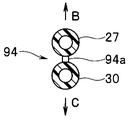
- the air supply & suction tube device 93 includes an air supply & suction tube 94 in which the air supply tube 27 and the suction tube 30 are unified, and the air supply & suction tube 94.
- a tube connector 95 which is integrally provided on the base end side of the air supply base and is press-fitted into the air supply base receiver 26 and the suction base receiver 29, respectively, and the distal end (terminal) of the air supply & suction tube device 93 The side is separated (branched) into an air supply tube 27 and a suction tube 30, and an air supply trocar connection base 94 a and a suction trocar connection base 94 b are provided at the respective separated ends.
- the tube connector 95 has a substantially disk shape and is set to have an outer diameter that fits into the recess of the tube connector receiver 91.
- the tube connector 95 is provided with an air supply base 95a and a suction base 95b that are press-fitted into the air supply base receiver 26 and the suction base receiver 29 of the tube connector receiver 91, respectively.
- the protrusion 95c inserted into the concave portion 92 is provided so as to protrude.
- a lock mechanism may be provided so that it cannot be removed unless it is pulled out with a force greater than a threshold value.
- the air supply base 95a and the suction base 95b are set to have outer diameters that fit into the inner diameters of the air supply base 95a and the suction base 95b, respectively. 96b is stored.
- the O-rings 96a and 96b protrude outward from the outer peripheral surfaces of the air supply base 95a and the suction base 95b, and the air supply base 95a and the suction base 95b are press-fitted into the air supply base 26 and the suction base 29, respectively.
- the air supply base 95a and the suction base 95b are connected to the air supply base receiver 26 and the suction base receiver 29, respectively, in a state where the airtightness is maintained by being compressed (the O-rings 96a and 96b are respectively compressed).
- the protrusion 95 c is inserted into the protrusion receiving recess 92.
- the air supply base 95a and the suction base 95b can be connected to the air supply base 26 and the suction base 29 of the tube connector receiver 91 without error in a single connection operation (operation).
- a mesh-shaped filter 97 is arranged in the middle of a tube (or conduit) 95 d communicating with the suction tube 30 inside the tube connector 95, and the carbon dioxide gas when sucked from the tip side of the suction tube 30 is cleaned with carbon dioxide. The gas can be filtered.
- FIG. 19 shows a cross-sectional structure of the air supply & suction tube 94.
- the air supply & suction tube 94 has a structure in which the air supply tube 27 and the suction tube 30 are adjacently connected (or integrated) by the thin wall portion 94c.
- the air supply tube 27 and the suction tube 30 are combined into one (except for the end side), the air supply of the apparatus main body 21 of the insufflation apparatus is performed. Connection to the base receiver 26 and the suction base receiver 29 can be facilitated.
- the tube connector 95 can be connected to the tube connector receiver 91 at one location in the apparatus main body 21, and erroneous connection can be reliably prevented by the recess 92 and the protrusion 95c.
- the mark is attached to the distal end side of the air supply & suction tube 94, erroneous connection when connecting to the trocar can be prevented.
- both tubes can be easily separated, and the surgeon can adjust the length of the separated part according to the preference of the surgeon and the placement at the time of surgery, etc. it can.
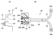
- a modified configuration as shown in FIG. 18 As a modified example of the air supply / suction tube device 93 shown in FIG. 18, a modified configuration as shown in FIG.
- the air / suction tube device 93B shown in FIG. 20 is a tube 95d having a filter 97 in the tube connector 95 in the air / suction tube device 93 shown in FIG.
- the end portions of the protruding trap bottle tubes 98 a and 98 b are inserted into the trap bottle 99.
- the filter 97 is disposed on the side of the trap bottle tube 98a that communicates with the suction cap 95b.
- the other configuration is the same as that shown in FIG.
- the trap bottle 99 is inserted in the middle of the suction tube 30. Therefore, not only the gas containing smoke in the abdominal cavity can be sucked through the suction tube 30, but also bodily fluids and blood can be sucked.
- the aspirated body fluid, blood, and the like are stored in the trap bottle 99, and the smoke floating in the carbon dioxide gas can be removed by the filter 97.
- the other effects are the same as those of the configuration of FIG. In FIG. 18 and the like, the case where the outer shape of the tube connector 95 and the tube connector receiver 91 is circular has been described. However, as shown in FIG. 21, the tube connector 95 may be shaped like a triangle, for example. . In this case, the protrusion 92 is unnecessary.
- FIG. 22 shows such a configuration.
- the tube connector receiver 91C shown in FIG. 22 (A) is provided with a storage portion in which the filter 97 is mounted by increasing the depth of the concave portion of the suction connector receiver 29 in the tube connector receiver 91 of FIG. After the filter 97 is attached to the housing portion, the tube connector 95 shown in FIG.
- carbon dioxide gas as a predetermined gas is circulated using the fluid pump 54 provided in the apparatus main body 21, so that the apparatus main body 21 is reduced in size and cost.
- the suction device 24 outside the apparatus main body 21 may be used for the circulation of carbon dioxide gas as follows.
- the insufflation apparatus 8F in FIG. 23 is, for example, in the configuration of the insufflation apparatus 8E in FIG. Receiving) 24b is connected to the cap receiver 25c of the apparatus main body 21 through the connecting pipe 25b.
- a fluid pump (simply abbreviated as “pump”) 24c not shown in FIG. 11 is indicated by a dotted line.
- the cap receiver 25 c is connected to the air supply pipe 41 or the circulation pipe 43 through which the flow rate adjusting valve 45 and the flow sensor 46 join via the second circulation pipe 43 b. Further, the suction port 24e of the fluid pump 24c is connected to the trigger receiver 24a. In the middle of the second circulation conduit 43b, there is provided a switching valve 51b for switching the communicating conduit, and the switching of the switching valve 51b is controlled by the control circuit 55a.
- the control circuit 55a normally sets the switching valve 51b in a state where the pipe line 43b on the cap receiver 25c side communicates with the exhaust pipe line 43c side as indicated by an arrow D. In this state, when the fluid pump 24c of the suction device 24 is set to the operating state, the sucked carbon dioxide gas is exhausted to the outside through the exhaust pipe 43c.
- the control circuit 55a causes the circulation pipe 43b on the side of the cap receiver 25c to be connected to the air supply pipe 41 (or the connection pipe) as indicated by the arrow E in the switching valve 51b. 43) Switch to communicate with the side. Further, the control circuit 55a opens the first electromagnetic valve 51. In this case, the carbon dioxide gas sucked by the fluid pump 24c of the suction device 24 is supplied to the air supply pipe 41 (or connection pipe 43), and further passed through the flow rate sensor 46 to the air supply tube 27 side. To air. That is, in this case, the carbon dioxide sucked by the suction device 24 (internal fluid pump) is circulated in parallel with the case where the carbon dioxide sucked by the fluid pump 54 is circulated. Other configurations are the same as those in FIG.
- a suction device 24 as a suction source disposed outside the housing of the apparatus main body 21 and an exhaust port (discharge port) for exhausting (discharging) a predetermined gas after suction in the suction source.
- Side and a second circulation pipe 43b serving as a fourth pipe connected to the first pipe where the other end is connected to the flow rate variable portion and the flow rate sensor 46;
- the exhaust pipe 43c is provided so as to branch on the four pipelines, and exhausts a predetermined gas that has passed (or flowed) through the fourth pipeline to the atmosphere, and has passed through the fourth pipeline.
- a switching valve 51b that selectively communicates a predetermined gas to one of the first pipeline side and the exhaust pipeline side 43c, and the control circuit 55a serving as a control unit circulates as a first operation mode.
- the predetermined gas sucked by the suction source Fourth conduit performs control so as to circulate the first trocar 28 through the first conduit (or subject) to the side.
- the suction device 24 internal fluid pump 24c outside the device main body 21 is used in addition to circulating the carbon dioxide gas by the fluid pump 54 inside the device main body 21. Carbon dioxide can be circulated.
- the insufflation apparatus 8F in FIG. 23 has been described as the configuration of the modified example of the second embodiment, but can also be applied to the insufflation apparatus 8 in FIG. 2 and other insufflation apparatuses. In the embodiments including the above-described modifications, embodiments configured by rearranging a part of these configurations also belong to the present invention.
- the air supply tube 27 and the suction tube 30 side in FIG. 23 may be used as the air supply & suction tube device 93 shown in FIG.
- the apparatus main body 21 side is also structured so that the air supply / suction tube apparatus 93 can be connected.
- the air supply tube 27 and suction tube 30 side in FIG. 23 may be replaced with those shown in FIG. 20 or FIG.
Landscapes
- Health & Medical Sciences (AREA)
- Life Sciences & Earth Sciences (AREA)
- Surgery (AREA)
- General Health & Medical Sciences (AREA)
- Biomedical Technology (AREA)
- Veterinary Medicine (AREA)
- Public Health (AREA)
- Animal Behavior & Ethology (AREA)
- Heart & Thoracic Surgery (AREA)
- Engineering & Computer Science (AREA)
- Biophysics (AREA)
- Nuclear Medicine, Radiotherapy & Molecular Imaging (AREA)
- Medical Informatics (AREA)
- Molecular Biology (AREA)
- Radiology & Medical Imaging (AREA)
- Physics & Mathematics (AREA)
- Pathology (AREA)
- Optics & Photonics (AREA)
- Anesthesiology (AREA)
- Hematology (AREA)
- Endoscopes (AREA)
- Surgical Instruments (AREA)
- External Artificial Organs (AREA)
Abstract
Description
また、電気メスを用いて処置を行った場合には、腹腔内に煙等が発生して観察を妨げるような場合のために、腹腔内に発生した煙を吸引装置により吸引して、腹腔の外部に排煙する。しかし、吸引により、腹腔内の気体の圧力が降下するために、送気源となるボンベから新しい炭酸ガスを送気することが必要になり、炭酸ガスの消費量が増大する欠点がある。
このように炭酸ガスの消費量が増大する欠点を解消するための従来例としての日本国特表2013-505812号公報においては、吸引した炭酸ガスを大気に開放しないで、フィルタを有する装置内で流体ポンプにより気体を循環させ、フィルタにより煙を除去した気体を再び腹腔内に戻す構成を開示している。
本発明は上述した点に鑑みてなされたもので、所定の気体を循環させて再利用する動作モードで使用できると共に、腹腔内での煙の発生が多量になるような場合に対応した動作モードでも使用することができる気腹装置を提供することを目的とする。
(第1の実施形態)
図1に示すように内視鏡手術システム1は、ベッド2に載置された被検体としての患者3に対して手術を行うための外科手術装置としての電気メス装置4と、外科手術を内視鏡5を用いて観察するための内視鏡装置6と、内視鏡5による視野と電気メス7による手術する領域を確保するために手術対象となる腹部3a内を気腹する第1の実施形態の気腹装置8等を備える。なお、腹部3aが被検体を形成するよう定義しても良い。
電気メス装置4は、高周波電力を発生する電気メス電源装置11と、この電気メス電源装置11により発生した高周波電力がケーブル12を介して供給される電気メス7とにより構成され、術者は、電気メス7の把持部などに設けたスイッチを操作することにより、電気メス7の先端の例えばバイポーラ電極により把持された患部に高周波電流を流して、焼灼などの処置を行うことができる。電気メス7は、図示しないトラカールにより腹部3a内に挿入される。
光源装置34は、この光源装置で発生した照明光をライトガイドケーブル18を介して内視鏡5に供給(伝送)する。ライトガイドケーブル18を介して供給された照明光は、内視鏡5の挿入部19内の図示しないライトガイドを介して伝送され、挿入部19の先端の図示しない照明窓から外部に出射し、腹部3a内の患部等を照明する。
気腹装置8を構成する筐体で覆われた気腹装置本体(装置本体と略記)21は、腹部3a内を気腹するための所定の気体としての炭酸ガスを送気(供給)する送気源(又は供給源)としての炭酸ガスを高圧状態で収納した炭酸ガスボンベ(単にガスボンベ又はボンベと略記)22に接続するための送気源接続部としての接続口金受け23を有する。そして、装置本体21は、接続口金受け23に接続される接続管を介してガスボンベ22と接続される。
また、装置本体21は、上記ガスボンベ22による炭酸ガスを送気に適した適度の流量に調整した後、送気管路接続部としての送気口金受け26からこの送気口金受け26に一端が接続される送気管路を構成する可撓性を有する送気チューブ27を介して、この送気チューブ27の他端が接続される送気用トラカールとしての第1のトラカール28側に送気することができる。
また、装置本体21には、腹腔内の圧力を下げたり、上記電気メス7により処置した場合に発生する煙を吸引して除去することができるように吸引管路接続部としての吸引口金受け29が設けてあり、この吸引口金受け29には吸引管路を構成する可撓性を有する吸引チューブ30を介して、この吸引チューブ30の他端が接続される吸引用トラカールとしての第2のトラカール31と接続される。
また、装置本体21の前面には、各種の操作や設定を行うための操作パネル32(図面では単にパネルと略記)と、腹腔内の圧力や送気流量等の表示を行う表示器33とが設けてある。また、装置本体21には、術者等のユーザが足で踏む操作により、送気や吸引や排煙の指示操作を行うフットスイッチ14a,14bと、吸引装置24に対して、吸引動作のON/OFFを行う信号を送る通信ケーブル35を備える。なお、気腹装置8を、装置本体21の他に、該装置本体21に接続される送気チューブ27、吸引チューブ30を備えた装置として定義しても良いし、送気源と吸引源とを含めて定義しても良い。
送気用管路41には、減圧を行う減圧器44、流量を調整する(流量可変部を構成する)流量調整弁45と、流量を検出するセンサとしての流量センサ46と、圧力を計測する第1の圧力センサ47とが接続口金受け23に近い順序でそれぞれ配置されている。
循環用管路40上には、圧力を計測する第2の圧力センサ48が配置され、第2の管路を構成する吸引用管路42上には切り替えユニット49を構成する第1の電磁弁51が配置されている。
なお、接続管路43の他端は、流量調整弁45と流量センサ46との間の送気用管路41で合流する。接続管路43は、流体ポンプ54と第1の管路を形成する送気用管路41とを接続するとも言える。
また、第2の圧力センサ48は、切り替えユニット49よりも吸引口金受け29側となる位置の循環用管路40上に設けてある。
また、第1の電磁弁51は、循環用管路40よりも接続口金受け25側となる吸引用管路42上に設けてある。
また、制御基板55の制御回路55aには、流量センサ46により計測された流量の検出値、第1の圧力センサ47及び第2の圧力センサ48により計測された圧力値、操作パネル32の操作により入力される信号、フットスイッチ14a,14bによる操作信号などが入力される。
また、本実施形態においては、吸引口金受け29には、第2のトラカール31側から吸引された炭酸ガスに混入する煙等、炭酸ガス以外の微粒子などの通過を阻止して清浄な炭酸ガスを通すように濾過するように細かい網目構造を有する繊維等で形成されたフィルタ56を吸引チューブ30の端部付近に設けた吸引口金36が着脱自在に取り付けられる。本発明における第1の実施形態においては、吸引チューブ30の途中にフィルタ56を設けた吸引口金36を、装置本体21の吸引口金受け29に着脱自在に接続する構成にしている。
図2Bに示す第1変形例の構成のように吸引口金受け29にフィルタ56を着脱自在に接続することができる構成にしても良い。図2Bに示す第1変形例の気腹装置8Aは、第1の実施形態の気腹装置8において、第1の実施形態の装置本体21における吸引口金受け29にフィルタ装着部を設けると共に、装置本体21に特性検出回路63を設けた部分が異なる。
尤も、フィルタ56は、交換することが必要になるため、装置本体21側に設ける場合には、交換し易い位置となる吸引口金受け29の位置が有力な位置(場所)となる。吸引チューブ30は、使い捨て(ディスポザブル)で使用されるために、図2に示す第1の実施形態の場合のように吸引チューブ30側にフィルタを一体的に設けるようにしても良い。この場合には、フィルタ56の構造として、後述する図18に示すような構造にしても良い。
図3は第1の実施形態の第1変形例における吸引口金受け29付近の構造を示す。なお、図3(A)は吸引口金受け29を循環用管路40の中心軸に垂直な面で切断した断面図、図3(B)は図3(A)の右側から見た側面図、図3(C)はフィルタ56の断面図、図3(D)は吸引口金受け29の凹部にフィルタ56を装着した状態の断面図である。なお、フィルタ56に対してはハッチングを省略して示す。
図3(A)に示すように吸引口金受け29は、循環用管路40の端部にリング形状の第1の段差部61aと、この第1の段差部61aの外周側に形成されたリング形状の第2の段差部61bとを有する2段構造の凹部を有する。
なお、LED62aは、制御基板55からLED電源が供給されて発光する。LED62aは、循環用管路40の中心軸と略平行な方向に光を出射し、また受光素子62bも、循環用管路40の中心軸と略平行な方向(但し、出射方向と反対方向)からの光を受光する指向特性を有する。
この2段構造の凹部を有する吸引口金受け29には、図3(C)に示すフィルタ56が着脱自在に装着される。
図3(C)に示すフィルタ56は、図3(D)に示すように第2の段差部61bに嵌合するフィルタケース56a内に例えば2層の円板形状のフィルタ円板56bがスペーサを介挿して配置され、フィルタケース56a一方の面の中央には循環用管路40に嵌合して装着される装着用口金56cが設けられ、他方の面の中央には、吸引チューブ30の端部に設けた接続口金を接続するための吸引チューブ取り付け部56dが設けてある。
また、フィルタ円板56bは、LED62aの光を所定の割合で透過する特性を有する。そして、煙等の微粒子などがフィルタ円板56bを構成する網目に付着する量が多くなると、濾過特性が低下すると共に、受光素子62bの出力レベルが低下する。そして、本実施形態においては、受光素子62bの出力レベルとフィルタ56の濾過特性の関係に着目して、以下のように濾過特性が低下した場合、フィルタ56の交換を告知する手段を設けている。
制御回路55aは、濾過機能が低下した判定信号を受けると、フィルタ円板56b、又はフィルタ56を交換を促す告知情報を表示器33で表示するように制御する。このため、表示器33は、手術を行う術者等のユーザに対して、フィルタ56の濾過機能が低下し、交換を促す告知を行う告知部を形成する。
4種類の動作モードは、少なくとも流体ポンプ54を動作させて、フィルタ56で濾過した(所定の気体としての)炭酸ガスを(送気管路としての)送気チューブ27を介して第1のトラカール31(又は被検体)側に循環させるように送気する第1の動作モード(換言すると循環モード)と、流体ポンプ54の動作を停止させて、フィルタ56で濾過した炭酸ガスを吸引源となる吸引装置24に吸引して排出させる第2の動作モード(換言すると排煙モード)と、を含む。
また、循環モードの動作モードにおいては、制御回路55aは、吸引装置24、流量調整弁45、第1の電磁弁51をOFFにし、流体ポンプ54、第2及び第3の電磁弁52及び53をONにする。
また、排煙モードの動作モードにおいては、制御回路55aは、循環モードの場合のON,OFFを入れ替えたように制御する。具体的には、制御回路55aは、吸引装置24、流量調整弁45、第1の電磁弁51をONにし、流体ポンプ54、第2及び第3の電磁弁52及び53をOFFにする。
なお、図2Bに示す第1変形例では特性検出回路63を制御基板55の外部に設けた構成を示しているが、特性検出回路63を制御基板55の内部に設けるようにしても良い。
また、図1、図2A、図2Bにおいて、装置本体21の接続口金受け25に接続された接続管25aを吸引源となる吸引装置24に接続する構成を示しているが、手術を行う手術室の外部に設けた吸引装置に接続する構成にしても良い。
術者は、図5のステップS1に示すように腹腔内の圧力設定や送気する場合の送気流量の設定等の初期設定を操作パネル32等から行う。
初期設定の後、ステップS2に示すように制御回路55aは送気指示をモニタし、送気指示を待つ状態となる。術者は操作パネル32から送気指示の操作又は送気用のフットスイッチ14aを押下して送気指示の操作を行う。すると、制御回路55aは、送気指示有りの判定を行い、ステップS3に示すように制御回路55aは、送気指示に対応した送気モードで送気を行うように制御する。
この場合、流量センサ46は、送気用管路41を流れる炭酸ガスの流量を計測し、計測した値を制御回路55aに送る。また、圧力センサ48は吸引チューブ30を介して腹腔内の圧力を計測し、計測した値を制御回路55aに送る。ステップS4に示すように制御回路55aは、圧力センサ48等の計測値により腹腔内の圧力等をモニタする。
ステップS5に示すように制御回路55aは、圧力センサ48により取得した圧力(の計測値)が初期設定で設定された圧力に達したか否かを判定する。圧力センサ48による圧力が、設定の圧力に達していない判定結果の場合には、送気モードによる送気の処理を続行し、腹腔内の圧力等をモニタする。
ステップS5の処理の後、ステップS6に示すように制御回路55aは、流体ポンプ54を動作させ、循環モードで動作させるように制御する。つまり、制御回路55aは、図4の表で示す循環モードのように吸引装置24と第1の電磁弁51をOFFのまま、流量調整弁45をONからOFF、第2及び第3の電磁弁52、53をOFFからONにする。
この循環モードの場合には、流体ポンプ54により吸引チューブ30を介して腹腔内の炭酸ガスを吸引し、その際フィルタ56により濾過して清浄な炭酸ガスにし、流体ポンプ54により吸引した清浄な炭酸ガスを送気用管路41,送気チューブ27を介して再び腹腔内に戻す。
循環モードにおいてはステップS8に示すように制御回路55aは、排煙の指示スイッチがOFFからONにされたか否かを判定し、排煙の指示スイッチがOFFの場合にはステップS7の処理に戻り、循環モードの動作を続行する。
術者は、このような状態において、内視鏡5の観察下で電気メス7を用いて患部に対する処置を行うことができる。
制御回路55aは、図4において排煙モードを示すように流体ポンプ54、第2及び第3の電磁弁52、53をONからOFF、吸引装置24、流量調整弁45、第1の電磁弁51をOFFからONにする。
排煙モードにおいては、ガスボンベ22の炭酸ガスを流量調整された状態で送気チューブ27を介して腹腔内に送気すると共に、吸引装置24を動作状態に設定し、腹腔内の炭酸ガスを吸引チューブ30、循環用管路40、ONにされた第1の電磁弁51、第2の管路を形成する吸引用管路42を介して吸引装置24が吸引する。
また、ステップS10に示すように制御回路55aは排煙のスイッチがOFFにされたか否かをモニタしている。排煙のスイッチがONされたままの状態では、ステップS9の処理に戻り、排煙モードの動作を続行する。
排煙のスイッチがOFFにされた場合には制御回路55aは、ステップS11に示すように排煙モードを終了させ、ステップS12に示すように排煙モードの終了時における例えば圧力センサ47で計測した腹腔内の圧力が設定の圧力より低下しているか否かの判定を行う。
また、ステップS15に示すように制御回路55aは吸引の指示操作有りか否かの判定を行う。吸引の指示操作が無い場合には、ステップS14の処理に戻り、循環モードの動作が続行する。
この吸引モードの場合には、図4の吸引モードで示すように制御回路55aは、吸引装置24と第1の電磁弁51をON、流量調整弁45、流体ポンプ54、第2、第3の電磁弁52,53をOFFにして、ガスボンベ22からの炭酸ガスの送気を停止させた状態で、体腔内の炭酸ガスを吸引装置24により吸引する。
ステップS19に示すように制御回路55aは吸引モードから循環モードに移行するように制御する。
循環モードに移行した場合、第1の実施形態の構成の場合には、ステップS22の処理を行う。一方、第1変形例の場合には、点線で示すステップS20の処理に進む。
ステップS20に示すように特性検出回路63は、フィルタ56の濾過特性をモニタし、点線で示すステップS21に示すように濾過特性が使用可能な範囲内(又は濾過特性が許容できる範囲内)であるか否かを判定し、判定結果を制御回路55aに送る。ステップS21において過特性が使用可能な範囲内の判定結果の場合には、ステップS22の処理に進む。
一方、ステップS21の判定処理において、フィルタ56の濾過特性が低下し、使用可能な範囲外の判定結果の場合には制御回路55aは、点線で示すステップS23においてフィルタ56の交換を促す告知を行い、図5の処理を終了する。術者は、フィルタ56の交換を促す告知が行われた場合には、フィルタ56を交換して、再び図5のステップS1から同様の作業を行う。なお、図5においては、第1変形例の場合におけるステップS20においてフィルタ56の濾過特性をモニタし、ステップS21において判定する手順となっているが、例えばステップS1の処理を行っている場合に濾過特性をモニタ、さらに判定するようにしても良い。また、ステップS1以外における図5のステップS1からS22に至る途中で行うようにしても良い。
また、本実施形態の第1変形例によれば、フィルタ56の濾過特性をモニタし、フィルタ56が煙等により目詰まりして濾過特性が低下したような場合には、術者等のユーザに告知することができるようにしているので、術者が手術を円滑に行い易い環境を提供できる。
つまり、第1の実施形態の第1変形例においては、流量調整弁45により電気信号により流量を調整していたが、第2の変形例においては電空比例弁71を用いることにより、電空比例弁71から圧力を調整した炭酸ガスを流量センサ46側に出力する。このため、本変形例は、第1の実施形態の第1変形例における流量調整弁45により調整された(炭酸ガスの)流量を、電空比例弁71により調整された(炭酸ガスの)圧力に置換することにより第1の実施形態の第1変形例と殆ど同じ作用効果を有する。なお、本変形例として、図2Bに示す構成の気腹装置8Aに適用した場合で説明したが、図2Aに示す構成の気腹装置8に適用することもできる。この場合には、第1の実施形態と殆ど同じ作用効果を有する。
3方弁72は、吸引口金受け29側の循環用管路40を、少なくとも接続口金受け25側の吸引用管路42に連通する状態(第1の連通状態)と、流体ポンプ54に連通する状態(第2の連通状態)とに選択的に切り替え可能な機能を有する。なお、接続口金受け25側の吸引用管路42を流体ポンプ54に連通する状態(第3の連通状態)に切り替える機能は、必ずしも必要とされるものでない。このため、3方弁72の代わりに第1の連通状態と第2の連通状態と選択的に切り替える切り替え弁を用いても良い。切り替え弁又は3方弁72は、制御回路55aにより少なくとも第1の連通状態と第2の連通状態との切り替えが制御される。
本変形例は、第1の実施形態の第1変形例とほぼ同様の作用効果を有する。なお、本変形例として、図2Bに示す構成の気腹装置8Aに適用した場合で説明したが、図2Aに示す構成の気腹装置8に適用することもできる。この場合には、第1の実施形態と殆ど同じ作用効果を有する。
図9は、第1の実施形態の第4変形例の気腹装置8Dを示す。図9の気腹装置8Dは、図2Bの気腹装置8Aにおいて、第2の電磁弁52と第3の電磁弁53をそれぞれ逆止弁73と74で置換した装置本体21を備えた構成となる。循環用管路40上に配置した逆止弁73と接続管路43上に配置した逆止弁74は、図9上において矢印Aで示す1方向に流れる気体を通すが、矢印Aの方向と逆方向に流れる気体に対しては、通過を阻止する逆止弁の機能を持つ。
送気モードの場合には、逆止弁73,74はそれぞれ実質的に閉の動作状態となる。循環用管路43上の流体ポンプ54がOFFとなるため、この流体ポンプ54は循環用管路40及び接続管路43を炭酸ガスが通過することを阻止する。従って、仮に逆止弁73や74が開になろうとしても流体ポンプ54が炭酸ガスが通過することを阻止するため、流体ポンプ54がOFFの場合には逆止弁73,74はそれぞれ実質的に閉の動作状態となる。
一方、循環モードの場合には、流体ポンプ54がONとなり、逆止弁73,74は炭酸ガスが矢印Aの方向に流れる動作に対して開となり、炭酸ガスを循環させるように作用する。
また、排煙モードと吸引モードの場合には、送気モードの場合と同様に、流体ポンプ54がOFFとなるため、逆止弁73,74はそれぞれ実質的に閉の動作状態となる。本変形例の場合には、第1の実施形態の場合における制御回路55aによる制御内容を削減して、第1の実施形態の第1変形例の場合と殆ど同様の作用効果を持つようにできる。なお、本変形例として、図2Bに示す構成の気腹装置8Aに適用した場合で説明したが、図2Aに示す構成の気腹装置8に適用することもできる。この場合には、第1の実施形態と殆ど同じ作用効果を有する。
次に本発明の第2の実施形態を説明する。図11は本発明の第2の実施形態の気腹装置8Eを示す。この気腹装置8Eは、図2Bの気腹装置8Aにおいて、第3の電磁弁53の代わりに図9において説明した逆止弁74を用いた装置本体21を備える。また、本実施形態においては、図2Bの特性検出回路63を用いることなく、フィルタ56Eのフィルタ特性の低下を検出する手段を備えている。
図12は、本実施形態における吸引口金受け29付近の構造を示す。図12(A)は、吸引口金受け29付近の構造を示し、図12(B)は、この吸引口金受け29の凹部に嵌合して着脱自在に装着されるフィルタ56Eを示す。
第1の実施形態の第1変形例においては、吸引口金受け29を2段構造の凹部を備える構成にしていたが、本実施形態においては、1段の凹部を備える構成にし、LED62a、受光素子62bを設けていない。
本実施形態においては、各動作モードにおいて吸引装置24、流量調整弁、流体ポンプ54、電磁弁51、52、逆止弁74は図13に示すような開閉状態となる。図13において、逆止弁74以外は図4と同じ内容であり、逆止弁74は図10において示した開閉状態と同じである。
本実施形態の代表的な動作内容は、図5と同様の処理となる。但し、本実施形態では第3の電磁弁53の制御を行うことなく、逆止弁74がその機能を代替する。
具体的には、第1の実施形態においては、制御回路55aは、循環モードの場合のみにおいて第3の電磁弁53を開にし、それ以外では閉にするように制御していた。これに対して、本実施形態においては、制御回路55aは、循環モードの場合のみにおいて流体ポンプ54を動作状態(ON)にし、それ以外ではOFFにする制御を行い、この制御に連動して、逆止弁74は循環モードの場合のみにおいて開となり、それ以外では実質的に閉となる。
濾過特性のモニタ・判定の処理が開始すると、ステップS31において制御回路55aは吸引装置24をONにした場合の圧力センサ48により計測される圧力の計測値Pを取り込み、ステップS32において制御回路55aは、予めメモリ55bに格納されている閾値Pthと比較する。なお、この場合、流量調整弁45は閉で、圧力センサ47は腹腔内の圧力を計測する。
換言すると、圧力センサ48の圧力Pは、吸引装置24により吸引圧力をより反映する圧力に低下する。このため、予め、交換した方が望ましいと思われる境界となる閾値Pthをメモリ55bに格納する。そして、制御回路55aは圧力Pが閾値Pth以上では使用可能な範囲と判定し、ステップS22の処理に移り、逆に圧力Pが閾値Pth未満の場合にはステップS23のフィルタ交換を促す告知の処理に移る。
なお、図14Aに示す処理を行う代わりに、図14Bに示すような特性判定回路63Eを設けるようにしても良い。図14Bに示す特性判定回路63Eは、圧力センサ48の圧力Pを取得する取得回路76aと、圧力Pと閾値Pthとを比較する比較回路76bとを有し、比較回路76bは比較結果を制御回路55aに出力する。制御回路55aは、特性判定回路63Eによる判定結果に対応した処理を行う。なお、閾値Pthは、上述のようにメモリ55bに予め格納され、閾値回路(図面では単に閾値と略記)76cが読み出して比較回路76bに出力する。
フィルタ56Eが目詰まりしていない状態から、フィルタ56Eが目詰まりする状態になると、フィルタ56Eを通る炭酸ガスの流量が低下する。このため、予め流量の閾値Fthを設定し、この閾値Fth未満の流量となる状態を目詰まりの状態と判定し、交換を促すようにすれば良い。
しかし、フィルタ56Eにおける内部のフィルタ円板56bが交換できるような構造にした場合、フィルタ円板56bを内装しない状態のフィルタ56Eを介挿して吸引口金受け29に吸引チューブ30の端部の接続口金を接続する可能性がある。このようにケース内のフィルタ(円板56b)を交換可能にしたタイプのフィルタの場合には、フィルタを用いないで、吸引口金受け29に吸引チューブ30の端部の接続口金を接続して使用してしまう場合があり得る。
図14Cの流量センサ77を備えた気腹装置(8Eとする)の電源を投入し、気腹装置8Eの各部が動作状態となる。制御回路55aは、最初のステップS41において吸引装置24と第1の電磁弁51とを動作状態に設定する。なお、ステップS41の処理を行う場合、吸引チューブ30の末端を、患者3の腹部3aに刺入された第2のトラカール31には接続しない状態にする(例えば、吸引チューブ30の末端を大気に開口する状態にする)。
次のステップS42において制御回路55aは、流量センサ77により計測される流量F2を取得する。
ステップS43の判定処理においてF2th1<F2<F2thの判定結果を満たさない場合には、次のステップS44において制御回路55aは、フィルタ56Eの装着(接続)を促す旨の告知を行った後、次のステップS45において制御回路55aは、フィルタ装着(接続)に要する適宜の時間(例えば10~20秒)の経過を待つ。ステップS45における適宜の時間の経過後、ステップS43の処理に戻る。一方、ステップS43の判定処理においてF2th1<F2<F2thを満足する判定結果の場合には、フィルタ円板56bが内装されたフィルタ56Eが吸引口金受け29に装着(接続)されていると判定する。そして、術者は吸引チューブ30の末端を第2のトラカール31に接続し、図5のステップS1の初期設定の処理を行う。
図14Cの構成又は図15の処理によりフィルタ装着(接続)の検出を行う他に、図16に示すような構成にして、フィルタ装着(接続)の検出を行うようにしても良い。但し、図16の構成においては、フィルタケース56a内のフィルタ円板56bは交換できない構造(使いすてタイプ)である。
図16に示す構成においては、装置本体21の吸引口金受け29にフィルタ56Eが装着されているか否かを検出する装着検出装置81を設けている。図16(A)は吸引口金受け29の縦断面を示し、図16(B)は、この吸引口金受け29に着脱自在に接続(装着)されるフィルタ56Fの構造を断面図で示し、図16(C)は図16(A)の右側から見た吸引口金受け29の正面図を示す。
装着検出部82aは、それぞれ導線を介して抵抗(値)を検出する抵抗検出回路83に接続されている。
また、フィルタ56Fにおける装着用口金56cの外周面には、リング形状で所定の抵抗値を持つように設定された抵抗体84aが設けてある。従って、このフィルタ56Fの装着用口金56cを吸引口金受け29の凹部に装着した場合、対向する位置の装着検出部82aは、抵抗体84aを介して導通し、抵抗検出回路83は、抵抗体84aの抵抗を検出する状態となる。抵抗検出回路83は、検出した抵抗値により吸引口金受け29の凹部にフィルタ56Fの装着用口金56cが装着されたことを確実に検出することができる。
吸引チューブ取り付け部56dの外径は、装着用口金56cより大きく設定してある。そして、この吸引チューブ取り付け部56dを吸引口金受け29の凹部に装着することができないようにしてフィルタ56Fの吸引口金受け29への誤接続(誤装着)を防止できる構造にしている。
図16の構成の場合には、フィルタ56Fが装着されているか否かを確実に検出することができる。図16の構成の場合には、実際に手術を行う前に制御回路55aは、抵抗検出回路83により検出された抵抗値からフィルタ56Fが装着されているか否かを確実に検出する。図16に示す構成の場合、図15のように吸引装置24等を動作させることや、吸引チューブ30の先端を第2のトラカール31に接続しない状態に設定することを必要としないメリットを有する。
また、上述した(変形例を含む)第1の実施形態又は第2の実施形態においては、別体の送気チューブ27と吸引チューブ30の各基端をそれぞれ送気口金受け26と吸引口金受け29に独立して着脱自在に接続する構成にしていたが、以下に説明するように一本化して接続作業を簡単化し、また誤接続を防止し易い構造にしても良い。
図17(A)は装置本体21における送気&吸引チューブ装置93のチューブコネクタ95が着脱自在に接続されるチューブコネクタ受け91の概略の断面形状を示し、図17(B)はその右側から見たチューブコネクタ受け91の正面図を示す。また、図18(B)は、送気&吸引チューブ装置93の全体を、その一部を断面図で示し、図18(A)は、図18(B)の送気&吸引チューブ装置93におけるチューブコネクタ95の正面図を示す。
一方、図18(B)に示すように送気&吸引チューブ装置93は、送気チューブ27と吸引チューブ30とが一本化された送気&吸引チューブ94と、この送気&吸引チューブ94の基端側に一体的に設けられ、送気口金受け26と吸引口金受け29にそれぞれ圧入して装着されるチューブコネクタ95と、を有し、送気&吸引チューブ装置93の先端(末端)側は、送気チューブ27と吸引チューブ30とに分離(分岐)され、分離された各先端に送気用トラカール接続口金94aと、吸引用トラカール接続口金94bとが設けてある。
また、チューブコネクタ95には、チューブコネクタ受け91の送気口金受け26と吸引口金受け29とにそれぞれ圧入される送気口金95aと吸引口金95bとが突出するように設けてあり、さらに突起受け用凹部92に挿入される突起95cが突出するように設けてある。なお、突起95cを突起受け用凹部92に挿入した場合、閾値以上の力で引き抜く操作しないと外れないようなロック機構を設けるようにしても良い。
送気口金95aと吸引口金95bは、送気口金95aと吸引口金95bの内径にそれぞれ嵌合する外径に設定されており、各外周面に設けた周溝には気密用のOリング96a,96bが収納されている。
また、チューブコネクタ95の内部において吸引チューブ30に連通するチューブ(又は管路)95dの途中に網目形状のフィルタ97を配置し、吸引チューブ30の先端側から吸引した際の炭酸ガスを清浄な炭酸ガスに濾過することができるようにしている。
また、図19は、送気&吸引チューブ94の横断面構造を示す。
図19に示すように送気&吸引チューブ94は、薄肉部94cにより、送気チューブ27と吸引チューブ30とが隣接して接続されている(又は一体化されている)構造であるため、両チューブを離間させる方向に力を加える(図19において矢印B,C)ことにより、薄肉部94cによる接続を破壊して簡単に両チューブを分離することができる。従って、送気&吸引チューブ94を実際に使用する場合、術者は、使用し易い長さに分離して使用することができる。
また、送気&吸引チューブ94の先端側にはそれぞれマークが付けてあるので、トラカールに接続する際の誤接続を防止できる。また、両チューブを簡単に分離することができ、術者は術者の好みや手術する際の配置等に応じて分離した部分の長さを使用し易い長さに調整して使用することができる。
図18に示した送気&吸引チューブ装置93の変形例として図20に示すように変形した構成にしても良い。
なお、図18等においては、チューブコネクタ95やチューブコネクタ受け91の外形を円形状にした場合で説明したが、図21に示すようにチューブコネクタ95を例えば3角形のような形状にしても良い。この場合には、突起92は不必要となる。
図22(A)に示すチューブコネクタ受け91Cは、図18のチューブコネクタ受け91において、吸引コネクタ受け29の凹部の深さを大きくしてフィルタ97を装着する収納部を設けている。この収納部にフィルタ97を装着した後、フィルタ97を内装していない構造の図22(B)に示すチューブコネクタ95を装着する。図22(B)に示す送気&吸引チューブ装置93は、図18の送気&吸引チューブ装置93においてチューブコネクタ18内にフィルタ97を設けない構成である。このようにした場合にも、図18の送気&吸引チューブ装置93の場合とほぼ同様の作用効果を有する。
図23の気腹装置8Fは、例えば図11の気腹装置8Eの構成において、吸引装置24内の流体ポンプ24cの吐出口(又は排気口)24dに接続される吐出口金受け(又は排気口受け)24bに接続管25bを介して装置本体21の口金受け25cに接続する。図23においては、図11においては図示していなかった流体ポンプ(単にポンプと略記)24cを点線で示している。口金受け25cは、第2の循環用管路43bを介して流量調整弁45と流量センサ46とが合流する送気用管路41又は循環用管路43に接続される。また、流体ポンプ24cの吸入口24eは引口金受け24aと接続される。第2の循環用管路43bの途中には、連通する管路の切替を行う切替弁51bが設けてあり、この切替弁51bは制御回路55aにより切替が制御される。制御回路55aは、通常は切替弁51bを、矢印Dで示すように口金受け25c側の管路43bが排気管路43c側に連通する状態に設定している。この状態においては、吸引装置24の流体ポンプ24cが動作状態に設定された場合には、吸引した炭酸ガスを排気管路43cを介して外部に排気する。
この場合には、吸引装置24の流体ポンプ24cにより吸引した炭酸ガスを送気用管路41(又は接続管路43)側に送気し、さらに流量センサ46を通過させて送気チューブ27側に送気する。つまり、この場合には、流体ポンプ54により吸引した炭酸ガスを循環させる場合と並列的に、吸引装置24(内部の流体ポンプ)により吸引した炭酸ガスを循環させるようになる。
その他は、図11と同様の構成である。
図23の構成によれば、循環モードに設定した場合、装置本体21内部の流体ポンプ54により炭酸ガスを循環させる他に、装置本体21の外部の吸引装置24(内部の流体ポンプ24c)を用いて炭酸ガスを循環させることができる。
なお、図23の気腹装置8Fは、第2の実施形態の変形例の構成として説明したが、図2の気腹装置8や、その他の気腹装置に適用することもできる。
上述した変形例を含む実施形態において、これらの構成の一部を組み替えて構成される実施形態等も本発明に属する。例えば、図23における送気チューブ27及び吸引チューブ30側を、図18に示す送気&吸引チューブ装置93にしても良い。この場合には、装置本体21側も送気&吸引チューブ装置93が接続できる構造にする。また、図23における送気チューブ27及び吸引チューブ30側を、図20や,図22に示すものに置換しても良い。
Claims (15)
- 所定の気体を送気する送気源と接続するための送気源接続部と、
被検体に前記所定の気体を送気する送気管路を接続するための送気管路接続部と、
前記送気源接続部と前記送気管路接続部とを接続する第1の管路と、
前記被検体内から前記所定の気体を吸引する吸引管路を接続するための吸引管路接続部と、
前記被検体に対して前記前記所定の気体を循環させるためのポンプと、
前記吸引管路接続部と前記ポンプとを接続する循環用管路と、
前記ポンプと前記第1の管路とを接続する接続管路と、
前記所定の気体を吸引するための吸引源と接続する吸引源接続部と、
前記吸引源接続部と前記循環用管路とを接続する第2の管路と、
前記吸引管路接続部から吸引した前記所定の気体を前記第2の管路に流す状態と、前記ポンプを介して前記第1の管路に流す状態とを選択的に切り替える切り替えユニットと、
前記所定の気体を前記ポンプを介して前記被検体に循環させる第1の動作モードと、前記所定の気体を前記第2の管路を介して前記吸引源側に吸引する第2の動作モードと、で動作するように前記切り替えユニットを制御する制御部と、
を有することを特徴とする気腹装置。 - 前記切り替えユニットは、前記吸引源接続部側の前記第2の管路上に設けられる開閉可能な第1の開閉弁と、前記接続管路上に設けられ、開閉可能な第2の開閉弁及び前記循環用管路から前記接続管路側への1方向のみで前記所定の気体を通す逆止弁の一方と、を備えて構成されることを特徴とする請求項1に記載の気腹装置。
- 前記切り替えユニットは、前記吸引管路接続部に連通する前記循環用管路を、前記吸引源接続部側の前記第2の管路への連通と、前記ポンプへの連通との一方の連通を選択的に行う切替弁を用いて構成されることを特徴とする請求項1に記載の気腹装置。
- 更に前記第1の管路上に配置され、前記所定の気体の流量を可変する流量可変部と、前記吸引管路の途中又は前記循環用管路の途中に設けられ、前記所定の気体を清浄な所定の気体に濾過するフィルタと、を備え、
前記制御部は、前記第1のモードの場合には、前記流量可変部が通す流量を0に設定するように前記流量可変部を制御し、かつ前記切り替えユニットを前記吸引管路接続部が前記ポンプに連通する状態に切り替えるように制御すると共に、前記ポンプを動作状態に設定する制御を行うことにより、前記フィルタで濾過した前記所定の気体を前記送気管路を介して前記被検体に循環させることを特徴とする請求項1に記載の気腹装置。 - 更に前記第1の管路上に配置され、前記所定の気体の流量を可変する流量可変部を備え、
前記制御部は、前記第2のモードの場合には、前記切り替えユニットを前記吸引管路接続部が前記第2の管路に連通する状態に切り替えるように制御すると共に、前記吸引源を動作状態に設定し、前記被検体内の前記所定の気体を前記第2の管路を経由して前記吸引源側に吸引させ、さらに前記送気源による所定の気体を、前記流量可変部により調整された流量にして、前記送気管路を介して前記被検体内に送気するように制御することを特徴とする請求項1に記載の気腹装置。 - 更に前記第1の管路上に配置され、前記所定の気体の流量を可変する流量可変部を備え、
前記制御部は、前記ポンプの動作を停止させ、かつ前記吸引源による吸引を停止させると共に、前記送気源による前記所定の気体を前記流量可変部により調整された流量にして前記被検体内に送気する第3の動作モードで動作するように制御することを特徴とする請求項1に記載の気腹装置。 - 更に前記第1の管路上に配置され、前記所定の気体の流量を可変する流量可変部を備え、 前記制御部は、前記流量可変部が通す流量を0に設定し、且つ前記切り替えユニットを前記吸引管路接続部が前記第2の管路に連通する状態に設定する制御を行うと共に、前記吸引源を動作状態に設定し、前記被検体内の前記所定の気体を前記第2の管路を経由して前記吸引源側に吸引させる第4の動作モードで動作するように制御することを特徴とする請求項1に記載の気腹装置。
- 更に、前記吸引管路接続部に設けられ、前記所定の気体を濾過するフィルタを着脱自在に装着可能とするフィルタ装着部と、
前記フィルタの装着の有無を検出するフィルタ検出部と、
前記フィルタ検出部による検出結果を告知する告知部と、
を有することを特徴とする請求項1に記載の気腹装置。 - 更に、前記被検体から前記吸引管路を通って流れる前記所定の気体を濾過するフィルタと、
前記フィルタによる前記所定の気体を通す通過特性の低下を検出する特性低下検出部と、
前記特性低下検出部により検出された通過特性が所定値以下に低下した場合に告知を行う告知部と、
を有することを特徴とする請求項1に記載の気腹装置。 - 前記送気管路接続部に一端が接続される前記送気管路と前記吸引管路接続部に一端が接続される前記吸引管路とをそれぞれ可撓性チューブにより形成した送気チューブと吸引チューブと、前記送気チューブと前記吸引チューブとの少なくとも他端側を一体化した送気&吸引チューブと、前記送気&吸引チューブの他端に形成され、前記送気管路接続部と前記吸引管路接続部とをそれぞれ形成する送気チューブ接続用口金受けと吸引チューブ接続用口金受けとにそれぞれ同時に着脱自在に接続可能とする送気チューブ接続用口金と吸引チューブ接続用口金を設けたチューブコネクタを有することを特徴とする請求項1に記載の気腹装置。
- 更に、前記第1の管路上に設けられ、前記所定の気体の流量を可変する流量可変部と、前記第1の管路上における、前記流量可変部と前記送気管路接続部との間に設けられた流量センサと、前記第1の管路上における前記流量可変部と前記送気管路接続部との間に設けられた圧力センサと、前記接続管路上に設けられ、該接続管路を流れる前記所定の気体の開閉を行う開閉弁又は前記所定の気体を前記ポンプ側から前記接続管路側への一方方向にのみ流す逆止弁と、
前記送気源接続部、前記吸引源接続部、前記送気管路接続部、前記吸引管路接続部、前記第1の管路、前記流量可変部、前記流量センサ、前記圧力センサ、前記第2の管路、前記接続管路、前記ポンプ、前記開閉弁又は前記逆止弁、前記切り替えユニット、及び前記制御部が設けられた筐体と、
前記筐体の外部に配置された前記吸引源と、
前記吸引源による吸引後の前記所定の気体を排気する排気口に一端が接続され、他端が前記流量可変部と前記流量センサとが合流する前記第1の管路に接続される第2の循環用管路と、
前記第2の循環用管路上に設けられ、前記排気口側となる前記第2の循環用管路を大気に排気するための排気管路と、前記第1の管路側に選択的に連通させる切替弁と、
を備え、
前記制御部は、前記第1の動作モードの場合に、前記吸引源により吸引した前記所定の気体を前記第2の循環用管路、前記第1の管路を介して前記被検体側に循環させるように制御することを特徴とする請求項1に記載の気腹装置。 - 更に、前記送気源接続部、前記送気管路接続部、前記第1の管路、前記吸引管路接続部、前記ポンプ、前記循環用管路、前記接続管路、前記吸引源接続部、前記第2の管路、前記切り替えユニット、及び前記制御部が設けられた筐体と、
前記筐体の外部に配置された前記吸引源と、
前記吸引源による吸引後の前記所定の気体を排気する排気口側に一端が接続され、他端が前記第1の管路に接続される第2の循環用管路と、
前記第2の循環用管路上に分岐するように設けられ、前記第2の循環用管路を通る前記所定の気体を大気に排気するための排気管路と、
前記第2の循環用管路を通る前記所定の気体を前記第1の管路側と前記排気管路側との一方に選択的に連通させる切替弁と、
を備え、
前記制御部は、前記第1の動作モードの場合に、前記吸引源により吸引した前記所定の気体を前記 第2の循環用管路、前記第1の管路を介して前記被検体内に循環させるように制御することを特徴とする請求項1に記載の気腹装置。 - 更に、前記送気源接続部に接続され、前記所定の気体を送気する送気源と、
前記送気管路接続部に接続され、前記被検体に前記所定の気体を送気する前記送気管路と、
前記吸引管路接続部に接続され、前記被検体から前記所定の気体を吸引する吸引管路と、
前記第1の管路上に配置され、前記所定の気体の流量を可変する流量可変部と、
を備えることを特徴とする請求項8に記載の気腹装置。 - 更に、前記送気源接続部に接続され、前記所定の気体を送気する送気源と、
前記送気管路接続部に接続され、前記被検体に前記所定の気体を送気する前記送気管路と、
前記吸引管路接続部に接続され、前記被検体から前記所定の気体を吸引する吸引管路と、
を備えることを特徴とする請求項4に記載の気腹装置。 - 更に、前記送気源接続部に接続され、前記所定の気体を送気する送気源と、
前記送気管路接続部に接続され、前記被検体に前記所定の気体を送気する前記送気管路と、
前記吸引管路接続部に接続され、前記被検体から前記所定の気体を吸引する吸引管路と、
を備えることを特徴とする請求項5に記載の気腹装置。
Priority Applications (4)
| Application Number | Priority Date | Filing Date | Title |
|---|---|---|---|
| EP14835141.4A EP3009077A4 (en) | 2013-08-06 | 2014-06-05 | Pneumoperitoneum apparatus |
| CN201480041471.5A CN105431093B (zh) | 2013-08-06 | 2014-06-05 | 气腹装置 |
| JP2015509238A JP5830625B2 (ja) | 2013-08-06 | 2014-06-05 | 気腹装置 |
| US14/980,717 US20160106934A1 (en) | 2013-08-06 | 2015-12-28 | Insufflation apparatus |
Applications Claiming Priority (2)
| Application Number | Priority Date | Filing Date | Title |
|---|---|---|---|
| JP2013-163551 | 2013-08-06 | ||
| JP2013163551 | 2013-08-06 |
Related Child Applications (1)
| Application Number | Title | Priority Date | Filing Date |
|---|---|---|---|
| US14/980,717 Continuation US20160106934A1 (en) | 2013-08-06 | 2015-12-28 | Insufflation apparatus |
Publications (1)
| Publication Number | Publication Date |
|---|---|
| WO2015019695A1 true WO2015019695A1 (ja) | 2015-02-12 |
Family
ID=52461039
Family Applications (1)
| Application Number | Title | Priority Date | Filing Date |
|---|---|---|---|
| PCT/JP2014/064938 WO2015019695A1 (ja) | 2013-08-06 | 2014-06-05 | 気腹装置 |
Country Status (5)
| Country | Link |
|---|---|
| US (1) | US20160106934A1 (ja) |
| EP (1) | EP3009077A4 (ja) |
| JP (1) | JP5830625B2 (ja) |
| CN (1) | CN105431093B (ja) |
| WO (1) | WO2015019695A1 (ja) |
Cited By (11)
| Publication number | Priority date | Publication date | Assignee | Title |
|---|---|---|---|---|
| JP2016209344A (ja) * | 2015-05-11 | 2016-12-15 | オリンパス株式会社 | 気腹システム |
| JP2016209345A (ja) * | 2015-05-11 | 2016-12-15 | オリンパス株式会社 | 気腹装置 |
| WO2017057030A1 (ja) * | 2015-10-02 | 2017-04-06 | オリンパス株式会社 | 循環排煙装置 |
| JPWO2017057065A1 (ja) * | 2015-10-01 | 2018-05-24 | オリンパス株式会社 | 循環排煙システム |
| JP2018519921A (ja) * | 2015-07-02 | 2018-07-26 | ノースゲート テクノロジーズ インコーポレイテッドNorthgate Technologies Inc. | ガス再循環システム |
| JP2018519923A (ja) * | 2015-06-30 | 2018-07-26 | サージクエスト, インク.Surgiquest, Inc. | 多モード外科用気体送達システムのための一体化された気密シールを伴う多経路濾過アセンブリ |
| WO2018180074A1 (ja) * | 2017-03-27 | 2018-10-04 | オリンパス株式会社 | 挿入装置、挿入装置の動作方法 |
| CN108697309A (zh) * | 2016-03-16 | 2018-10-23 | 奥林巴斯株式会社 | 医疗用配管部件 |
| CN109937064A (zh) * | 2016-11-14 | 2019-06-25 | 康美公司 | 被配置成当在体腔中使用抽吸时保持稳定的体腔压力的多模态手术气体递送系统 |
| CN110049798A (zh) * | 2016-12-16 | 2019-07-23 | Wom医药世界公司 | 具有经过改进的放气装置的医用泵 |
| WO2019198324A1 (ja) * | 2018-04-11 | 2019-10-17 | オリンパス株式会社 | 内視鏡用流体制御装置 |
Families Citing this family (154)
| Publication number | Priority date | Publication date | Assignee | Title |
|---|---|---|---|---|
| US11871901B2 (en) | 2012-05-20 | 2024-01-16 | Cilag Gmbh International | Method for situational awareness for surgical network or surgical network connected device capable of adjusting function based on a sensed situation or usage |
| US11504192B2 (en) | 2014-10-30 | 2022-11-22 | Cilag Gmbh International | Method of hub communication with surgical instrument systems |
| JP6246417B2 (ja) * | 2015-05-07 | 2017-12-13 | オリンパス株式会社 | 内視鏡システム及び内視鏡 |
| WO2018089986A2 (en) * | 2016-11-14 | 2018-05-17 | Conmed Corporation | Multimodal surgical gas delivery system having continuous pressure monitoring of a continuous flow of gas to a body cavity |
| CN106510839B (zh) * | 2016-11-24 | 2019-11-19 | 上海大学 | 外科手术智能排烟系统和方法 |
| CN106725893A (zh) * | 2017-01-19 | 2017-05-31 | 长江大学 | 一种腹腔镜烟雾自动清除系统和方法 |
| WO2018191600A1 (en) * | 2017-04-13 | 2018-10-18 | Smith & Nephew, Inc. | Cannula identification for use with fluid management |
| US11911045B2 (en) | 2017-10-30 | 2024-02-27 | Cllag GmbH International | Method for operating a powered articulating multi-clip applier |
| US11801098B2 (en) | 2017-10-30 | 2023-10-31 | Cilag Gmbh International | Method of hub communication with surgical instrument systems |
| US11311342B2 (en) | 2017-10-30 | 2022-04-26 | Cilag Gmbh International | Method for communicating with surgical instrument systems |
| US11071560B2 (en) | 2017-10-30 | 2021-07-27 | Cilag Gmbh International | Surgical clip applier comprising adaptive control in response to a strain gauge circuit |
| US11291510B2 (en) | 2017-10-30 | 2022-04-05 | Cilag Gmbh International | Method of hub communication with surgical instrument systems |
| US11229436B2 (en) | 2017-10-30 | 2022-01-25 | Cilag Gmbh International | Surgical system comprising a surgical tool and a surgical hub |
| US11317919B2 (en) | 2017-10-30 | 2022-05-03 | Cilag Gmbh International | Clip applier comprising a clip crimping system |
| US11564756B2 (en) | 2017-10-30 | 2023-01-31 | Cilag Gmbh International | Method of hub communication with surgical instrument systems |
| US11510741B2 (en) | 2017-10-30 | 2022-11-29 | Cilag Gmbh International | Method for producing a surgical instrument comprising a smart electrical system |
| US11045197B2 (en) | 2017-10-30 | 2021-06-29 | Cilag Gmbh International | Clip applier comprising a movable clip magazine |
| FR3085830A1 (fr) * | 2018-09-18 | 2020-03-20 | Smices | Dispositif portatif de circulation de gaz entre trocarts et accessoire pour endoscope |
| US10594931B2 (en) | 2017-12-12 | 2020-03-17 | Verily Life Sciences Llc | Reducing smoke occlusion in images from surgical systems |
| US11147607B2 (en) | 2017-12-28 | 2021-10-19 | Cilag Gmbh International | Bipolar combination device that automatically adjusts pressure based on energy modality |
| US11100631B2 (en) | 2017-12-28 | 2021-08-24 | Cilag Gmbh International | Use of laser light and red-green-blue coloration to determine properties of back scattered light |
| US11857152B2 (en) | 2017-12-28 | 2024-01-02 | Cilag Gmbh International | Surgical hub spatial awareness to determine devices in operating theater |
| US11659023B2 (en) | 2017-12-28 | 2023-05-23 | Cilag Gmbh International | Method of hub communication |
| US20190201039A1 (en) | 2017-12-28 | 2019-07-04 | Ethicon Llc | Situational awareness of electrosurgical systems |
| US11832840B2 (en) | 2017-12-28 | 2023-12-05 | Cilag Gmbh International | Surgical instrument having a flexible circuit |
| US11253315B2 (en) | 2017-12-28 | 2022-02-22 | Cilag Gmbh International | Increasing radio frequency to create pad-less monopolar loop |
| US10966791B2 (en) | 2017-12-28 | 2021-04-06 | Ethicon Llc | Cloud-based medical analytics for medical facility segmented individualization of instrument function |
| US11696760B2 (en) | 2017-12-28 | 2023-07-11 | Cilag Gmbh International | Safety systems for smart powered surgical stapling |
| US11278281B2 (en) | 2017-12-28 | 2022-03-22 | Cilag Gmbh International | Interactive surgical system |
| US11202570B2 (en) | 2017-12-28 | 2021-12-21 | Cilag Gmbh International | Communication hub and storage device for storing parameters and status of a surgical device to be shared with cloud based analytics systems |
| US11589888B2 (en) | 2017-12-28 | 2023-02-28 | Cilag Gmbh International | Method for controlling smart energy devices |
| US11410259B2 (en) | 2017-12-28 | 2022-08-09 | Cilag Gmbh International | Adaptive control program updates for surgical devices |
| US11896443B2 (en) | 2017-12-28 | 2024-02-13 | Cilag Gmbh International | Control of a surgical system through a surgical barrier |
| US11364075B2 (en) | 2017-12-28 | 2022-06-21 | Cilag Gmbh International | Radio frequency energy device for delivering combined electrical signals |
| US11284936B2 (en) | 2017-12-28 | 2022-03-29 | Cilag Gmbh International | Surgical instrument having a flexible electrode |
| US11069012B2 (en) | 2017-12-28 | 2021-07-20 | Cilag Gmbh International | Interactive surgical systems with condition handling of devices and data capabilities |
| US11291495B2 (en) | 2017-12-28 | 2022-04-05 | Cilag Gmbh International | Interruption of energy due to inadvertent capacitive coupling |
| US11612408B2 (en) | 2017-12-28 | 2023-03-28 | Cilag Gmbh International | Determining tissue composition via an ultrasonic system |
| US11389164B2 (en) | 2017-12-28 | 2022-07-19 | Cilag Gmbh International | Method of using reinforced flexible circuits with multiple sensors to optimize performance of radio frequency devices |
| US11179208B2 (en) | 2017-12-28 | 2021-11-23 | Cilag Gmbh International | Cloud-based medical analytics for security and authentication trends and reactive measures |
| US11423007B2 (en) | 2017-12-28 | 2022-08-23 | Cilag Gmbh International | Adjustment of device control programs based on stratified contextual data in addition to the data |
| US11324557B2 (en) | 2017-12-28 | 2022-05-10 | Cilag Gmbh International | Surgical instrument with a sensing array |
| US10944728B2 (en) | 2017-12-28 | 2021-03-09 | Ethicon Llc | Interactive surgical systems with encrypted communication capabilities |
| US20190201594A1 (en) * | 2017-12-28 | 2019-07-04 | Ethicon Llc | Method of sensing particulate from smoke evacuated from a patient, adjusting the pump speed based on the sensed information, and communicating the functional parameters of the system to the hub |
| US11304745B2 (en) | 2017-12-28 | 2022-04-19 | Cilag Gmbh International | Surgical evacuation sensing and display |
| US11786245B2 (en) | 2017-12-28 | 2023-10-17 | Cilag Gmbh International | Surgical systems with prioritized data transmission capabilities |
| US11432885B2 (en) | 2017-12-28 | 2022-09-06 | Cilag Gmbh International | Sensing arrangements for robot-assisted surgical platforms |
| US11559307B2 (en) | 2017-12-28 | 2023-01-24 | Cilag Gmbh International | Method of robotic hub communication, detection, and control |
| US11076921B2 (en) | 2017-12-28 | 2021-08-03 | Cilag Gmbh International | Adaptive control program updates for surgical hubs |
| US11096693B2 (en) | 2017-12-28 | 2021-08-24 | Cilag Gmbh International | Adjustment of staple height of at least one row of staples based on the sensed tissue thickness or force in closing |
| US11234756B2 (en) | 2017-12-28 | 2022-02-01 | Cilag Gmbh International | Powered surgical tool with predefined adjustable control algorithm for controlling end effector parameter |
| US11576677B2 (en) | 2017-12-28 | 2023-02-14 | Cilag Gmbh International | Method of hub communication, processing, display, and cloud analytics |
| US11612444B2 (en) | 2017-12-28 | 2023-03-28 | Cilag Gmbh International | Adjustment of a surgical device function based on situational awareness |
| US10987178B2 (en) | 2017-12-28 | 2021-04-27 | Ethicon Llc | Surgical hub control arrangements |
| US11602393B2 (en) | 2017-12-28 | 2023-03-14 | Cilag Gmbh International | Surgical evacuation sensing and generator control |
| US11213359B2 (en) | 2017-12-28 | 2022-01-04 | Cilag Gmbh International | Controllers for robot-assisted surgical platforms |
| US11132462B2 (en) | 2017-12-28 | 2021-09-28 | Cilag Gmbh International | Data stripping method to interrogate patient records and create anonymized record |
| US11832899B2 (en) | 2017-12-28 | 2023-12-05 | Cilag Gmbh International | Surgical systems with autonomously adjustable control programs |
| US10758310B2 (en) | 2017-12-28 | 2020-09-01 | Ethicon Llc | Wireless pairing of a surgical device with another device within a sterile surgical field based on the usage and situational awareness of devices |
| US11896322B2 (en) | 2017-12-28 | 2024-02-13 | Cilag Gmbh International | Sensing the patient position and contact utilizing the mono-polar return pad electrode to provide situational awareness to the hub |
| US11464535B2 (en) | 2017-12-28 | 2022-10-11 | Cilag Gmbh International | Detection of end effector emersion in liquid |
| US11446052B2 (en) | 2017-12-28 | 2022-09-20 | Cilag Gmbh International | Variation of radio frequency and ultrasonic power level in cooperation with varying clamp arm pressure to achieve predefined heat flux or power applied to tissue |
| US11424027B2 (en) | 2017-12-28 | 2022-08-23 | Cilag Gmbh International | Method for operating surgical instrument systems |
| US11633237B2 (en) | 2017-12-28 | 2023-04-25 | Cilag Gmbh International | Usage and technique analysis of surgeon / staff performance against a baseline to optimize device utilization and performance for both current and future procedures |
| US10943454B2 (en) | 2017-12-28 | 2021-03-09 | Ethicon Llc | Detection and escalation of security responses of surgical instruments to increasing severity threats |
| US11464559B2 (en) | 2017-12-28 | 2022-10-11 | Cilag Gmbh International | Estimating state of ultrasonic end effector and control system therefor |
| US11529187B2 (en) | 2017-12-28 | 2022-12-20 | Cilag Gmbh International | Surgical evacuation sensor arrangements |
| US11311306B2 (en) | 2017-12-28 | 2022-04-26 | Cilag Gmbh International | Surgical systems for detecting end effector tissue distribution irregularities |
| US11045591B2 (en) | 2017-12-28 | 2021-06-29 | Cilag Gmbh International | Dual in-series large and small droplet filters |
| US11257589B2 (en) | 2017-12-28 | 2022-02-22 | Cilag Gmbh International | Real-time analysis of comprehensive cost of all instrumentation used in surgery utilizing data fluidity to track instruments through stocking and in-house processes |
| US11304720B2 (en) | 2017-12-28 | 2022-04-19 | Cilag Gmbh International | Activation of energy devices |
| US11937769B2 (en) | 2017-12-28 | 2024-03-26 | Cilag Gmbh International | Method of hub communication, processing, storage and display |
| US11744604B2 (en) | 2017-12-28 | 2023-09-05 | Cilag Gmbh International | Surgical instrument with a hardware-only control circuit |
| US11903601B2 (en) | 2017-12-28 | 2024-02-20 | Cilag Gmbh International | Surgical instrument comprising a plurality of drive systems |
| US10932872B2 (en) | 2017-12-28 | 2021-03-02 | Ethicon Llc | Cloud-based medical analytics for linking of local usage trends with the resource acquisition behaviors of larger data set |
| US11273001B2 (en) | 2017-12-28 | 2022-03-15 | Cilag Gmbh International | Surgical hub and modular device response adjustment based on situational awareness |
| US11376002B2 (en) | 2017-12-28 | 2022-07-05 | Cilag Gmbh International | Surgical instrument cartridge sensor assemblies |
| US11969216B2 (en) | 2017-12-28 | 2024-04-30 | Cilag Gmbh International | Surgical network recommendations from real time analysis of procedure variables against a baseline highlighting differences from the optimal solution |
| US11559308B2 (en) | 2017-12-28 | 2023-01-24 | Cilag Gmbh International | Method for smart energy device infrastructure |
| US10892995B2 (en) | 2017-12-28 | 2021-01-12 | Ethicon Llc | Surgical network determination of prioritization of communication, interaction, or processing based on system or device needs |
| US11051876B2 (en) * | 2017-12-28 | 2021-07-06 | Cilag Gmbh International | Surgical evacuation flow paths |
| US11969142B2 (en) | 2017-12-28 | 2024-04-30 | Cilag Gmbh International | Method of compressing tissue within a stapling device and simultaneously displaying the location of the tissue within the jaws |
| US11026751B2 (en) | 2017-12-28 | 2021-06-08 | Cilag Gmbh International | Display of alignment of staple cartridge to prior linear staple line |
| US11864728B2 (en) | 2017-12-28 | 2024-01-09 | Cilag Gmbh International | Characterization of tissue irregularities through the use of mono-chromatic light refractivity |
| US11109866B2 (en) | 2017-12-28 | 2021-09-07 | Cilag Gmbh International | Method for circular stapler control algorithm adjustment based on situational awareness |
| US11786251B2 (en) | 2017-12-28 | 2023-10-17 | Cilag Gmbh International | Method for adaptive control schemes for surgical network control and interaction |
| US10755813B2 (en) | 2017-12-28 | 2020-08-25 | Ethicon Llc | Communication of smoke evacuation system parameters to hub or cloud in smoke evacuation module for interactive surgical platform |
| US11013563B2 (en) | 2017-12-28 | 2021-05-25 | Ethicon Llc | Drive arrangements for robot-assisted surgical platforms |
| US11056244B2 (en) | 2017-12-28 | 2021-07-06 | Cilag Gmbh International | Automated data scaling, alignment, and organizing based on predefined parameters within surgical networks |
| US11419630B2 (en) | 2017-12-28 | 2022-08-23 | Cilag Gmbh International | Surgical system distributed processing |
| US11678881B2 (en) | 2017-12-28 | 2023-06-20 | Cilag Gmbh International | Spatial awareness of surgical hubs in operating rooms |
| US11166772B2 (en) | 2017-12-28 | 2021-11-09 | Cilag Gmbh International | Surgical hub coordination of control and communication of operating room devices |
| US11304763B2 (en) | 2017-12-28 | 2022-04-19 | Cilag Gmbh International | Image capturing of the areas outside the abdomen to improve placement and control of a surgical device in use |
| US11666331B2 (en) | 2017-12-28 | 2023-06-06 | Cilag Gmbh International | Systems for detecting proximity of surgical end effector to cancerous tissue |
| US11304699B2 (en) | 2017-12-28 | 2022-04-19 | Cilag Gmbh International | Method for adaptive control schemes for surgical network control and interaction |
| US11818052B2 (en) | 2017-12-28 | 2023-11-14 | Cilag Gmbh International | Surgical network determination of prioritization of communication, interaction, or processing based on system or device needs |
| US11317937B2 (en) | 2018-03-08 | 2022-05-03 | Cilag Gmbh International | Determining the state of an ultrasonic end effector |
| US11571234B2 (en) | 2017-12-28 | 2023-02-07 | Cilag Gmbh International | Temperature control of ultrasonic end effector and control system therefor |
| US11540855B2 (en) | 2017-12-28 | 2023-01-03 | Cilag Gmbh International | Controlling activation of an ultrasonic surgical instrument according to the presence of tissue |
| US10892899B2 (en) | 2017-12-28 | 2021-01-12 | Ethicon Llc | Self describing data packets generated at an issuing instrument |
| US11266468B2 (en) | 2017-12-28 | 2022-03-08 | Cilag Gmbh International | Cooperative utilization of data derived from secondary sources by intelligent surgical hubs |
| US11160605B2 (en) | 2017-12-28 | 2021-11-02 | Cilag Gmbh International | Surgical evacuation sensing and motor control |
| US11419667B2 (en) | 2017-12-28 | 2022-08-23 | Cilag Gmbh International | Ultrasonic energy device which varies pressure applied by clamp arm to provide threshold control pressure at a cut progression location |
| US11308075B2 (en) | 2017-12-28 | 2022-04-19 | Cilag Gmbh International | Surgical network, instrument, and cloud responses based on validation of received dataset and authentication of its source and integrity |
| US10849697B2 (en) | 2017-12-28 | 2020-12-01 | Ethicon Llc | Cloud interface for coupled surgical devices |
| WO2019155661A1 (ja) * | 2018-02-06 | 2019-08-15 | オリンパス株式会社 | 気腹器用コネクタおよび気腹装置 |
| US11259830B2 (en) | 2018-03-08 | 2022-03-01 | Cilag Gmbh International | Methods for controlling temperature in ultrasonic device |
| US11589915B2 (en) | 2018-03-08 | 2023-02-28 | Cilag Gmbh International | In-the-jaw classifier based on a model |
| US11707293B2 (en) | 2018-03-08 | 2023-07-25 | Cilag Gmbh International | Ultrasonic sealing algorithm with temperature control |
| WO2019176171A1 (ja) * | 2018-03-16 | 2019-09-19 | オリンパス株式会社 | 内視鏡及び内視鏡システム |
| US11278280B2 (en) | 2018-03-28 | 2022-03-22 | Cilag Gmbh International | Surgical instrument comprising a jaw closure lockout |
| US11471156B2 (en) | 2018-03-28 | 2022-10-18 | Cilag Gmbh International | Surgical stapling devices with improved rotary driven closure systems |
| US11197668B2 (en) | 2018-03-28 | 2021-12-14 | Cilag Gmbh International | Surgical stapling assembly comprising a lockout and an exterior access orifice to permit artificial unlocking of the lockout |
| US10973520B2 (en) | 2018-03-28 | 2021-04-13 | Ethicon Llc | Surgical staple cartridge with firing member driven camming assembly that has an onboard tissue cutting feature |
| US11219453B2 (en) | 2018-03-28 | 2022-01-11 | Cilag Gmbh International | Surgical stapling devices with cartridge compatible closure and firing lockout arrangements |
| US11096688B2 (en) | 2018-03-28 | 2021-08-24 | Cilag Gmbh International | Rotary driven firing members with different anvil and channel engagement features |
| US11090047B2 (en) | 2018-03-28 | 2021-08-17 | Cilag Gmbh International | Surgical instrument comprising an adaptive control system |
| US11207067B2 (en) | 2018-03-28 | 2021-12-28 | Cilag Gmbh International | Surgical stapling device with separate rotary driven closure and firing systems and firing member that engages both jaws while firing |
| US11259806B2 (en) | 2018-03-28 | 2022-03-01 | Cilag Gmbh International | Surgical stapling devices with features for blocking advancement of a camming assembly of an incompatible cartridge installed therein |
| ES2870373T3 (es) | 2018-05-18 | 2021-10-26 | Verathon Inc | Sistema de endoscopio con un conjunto de rueda de control acoplado a cables de tracción |
| DE102018004211A1 (de) * | 2018-05-25 | 2019-11-28 | W.O.M. World Of Medicine Gmbh | Insufflationsvorrichtung und damit durchführbare Betriebsverfahren |
| CN108634999B (zh) * | 2018-07-16 | 2023-08-11 | 鹰利视医疗科技有限公司 | 一种带除烟雾功能的气腹机 |
| WO2020040651A1 (en) * | 2018-08-23 | 2020-02-27 | Fisher & Paykel Healthcare Limited | Supplementary continuous gas supply source for delivery to surgical cavities |
| CN108926319B (zh) * | 2018-08-29 | 2020-09-01 | 合肥工业大学 | 配置高清视像处理模块的移动智能一体化腔镜系统 |
| CN109124702B (zh) * | 2018-08-29 | 2020-09-01 | 合肥工业大学 | 配置气腹控制和中央控制模块的智能腔镜系统 |
| CN109363735A (zh) * | 2018-08-29 | 2019-02-22 | 合肥德铭电子有限公司 | 配置电磁抑制电路的一体化腔镜系统 |
| CN109124782B (zh) * | 2018-08-29 | 2020-09-22 | 合肥工业大学 | 智能一体化腔镜系统 |
| CN109350239A (zh) * | 2018-08-29 | 2019-02-19 | 合肥德易电子有限公司 | 具有目标定位功能的智能一体化机器人腔镜系统 |
| CN109151275B (zh) * | 2018-08-29 | 2021-03-09 | 合肥工业大学 | 具有实时腔镜视像增强处理功能的智能边缘计算系统 |
| CN109288548A (zh) * | 2018-08-29 | 2019-02-01 | 合肥德铭电子有限公司 | 具有气腹流量控制的自推荐式气腹仪 |
| CN109363614B (zh) * | 2018-08-29 | 2020-09-01 | 合肥德易电子有限公司 | 具有高清视像增强处理功能的智能一体化机器人腔镜系统 |
| CN109288487B (zh) * | 2018-08-29 | 2020-12-15 | 合肥德铭电子有限公司 | 具有高清视像处理和电磁抑制功能的智能腔镜系统 |
| CN109363736A (zh) * | 2018-09-10 | 2019-02-22 | 安徽省胸科医院 | 配置中央控制模块的一体化腔镜系统 |
| CN109077757B (zh) * | 2018-09-15 | 2020-07-14 | 山西省人民医院 | 一种腔镜手术使用的气腹控制装置及方法 |
| US11027078B2 (en) * | 2018-09-21 | 2021-06-08 | Conmed Corporation | Multi-modal five lumen gas circulation system for use in endoscopic surgical procedures |
| JP7150875B2 (ja) * | 2018-12-05 | 2022-10-11 | オリンパス株式会社 | 気腹システム、及び、気腹システムの作動方法 |
| CN109833081B (zh) * | 2018-12-17 | 2020-05-26 | 江苏人冠医疗科技有限公司 | 一种腹腔镜外科手术用气体灌注和再循环系统 |
| US11291444B2 (en) | 2019-02-19 | 2022-04-05 | Cilag Gmbh International | Surgical stapling assembly with cartridge based retainer configured to unlock a closure lockout |
| US11317915B2 (en) | 2019-02-19 | 2022-05-03 | Cilag Gmbh International | Universal cartridge based key feature that unlocks multiple lockout arrangements in different surgical staplers |
| US11751872B2 (en) | 2019-02-19 | 2023-09-12 | Cilag Gmbh International | Insertable deactivator element for surgical stapler lockouts |
| US11369377B2 (en) | 2019-02-19 | 2022-06-28 | Cilag Gmbh International | Surgical stapling assembly with cartridge based retainer configured to unlock a firing lockout |
| US11357503B2 (en) | 2019-02-19 | 2022-06-14 | Cilag Gmbh International | Staple cartridge retainers with frangible retention features and methods of using same |
| EP3983036A1 (en) * | 2019-06-13 | 2022-04-20 | Palliare Limited | A leak control system for an insufflation system, and a method for minimising leakage from an insufflation system |
| USD952144S1 (en) | 2019-06-25 | 2022-05-17 | Cilag Gmbh International | Surgical staple cartridge retainer with firing system authentication key |
| USD964564S1 (en) | 2019-06-25 | 2022-09-20 | Cilag Gmbh International | Surgical staple cartridge retainer with a closure system authentication key |
| USD950728S1 (en) | 2019-06-25 | 2022-05-03 | Cilag Gmbh International | Surgical staple cartridge |
| CN111388031B (zh) * | 2019-06-28 | 2021-08-10 | 深圳迈瑞生物医疗电子股份有限公司 | 一种气腹机及内窥镜设备 |
| EP3782528B1 (en) * | 2019-08-23 | 2023-04-19 | Chang Gul Hong | Fluid supply device for endoscope |
| CN111685831A (zh) * | 2020-06-15 | 2020-09-22 | 南京图格医疗科技有限公司 | 一种恒压变流式气腹机 |
| FR3113580A1 (fr) * | 2020-08-31 | 2022-03-04 | Smices | Dispositif de filtration de fumées d’opérations chirurgicales |
| WO2022243844A1 (de) * | 2021-05-17 | 2022-11-24 | W.O.M. World Of Medicine Gmbh | Kupplungsvorrichtung für eine medizintechnische pumpe |
| CN113598970B (zh) * | 2021-08-20 | 2024-02-02 | 重庆市人民医院 | 一种单孔腹腔镜手术用防刺伤循环排烟装置及排烟方法 |
| CN113694630A (zh) * | 2021-08-20 | 2021-11-26 | 深圳市安赐生物科技有限公司 | 一次性微创手术循环排烟过滤消杀系统和方法 |
| EP4355396A1 (en) * | 2021-09-30 | 2024-04-24 | Duke University | Multi-port, high-flow pneumoperitoneum and smoke evacuation distribution devices, systems, and methods |
Citations (6)
| Publication number | Priority date | Publication date | Assignee | Title |
|---|---|---|---|---|
| JPS6371245A (ja) * | 1986-09-10 | 1988-03-31 | ジエ−ムズ、エツチ、グツドサン | レーザ煙排出装置 |
| JPH05329164A (ja) * | 1992-05-29 | 1993-12-14 | Olympus Optical Co Ltd | 高速気腹装置 |
| JPH0975355A (ja) * | 1995-09-11 | 1997-03-25 | Olympus Optical Co Ltd | 気腹装置の吸引システム |
| JP2011167683A (ja) * | 2010-02-18 | 2011-09-01 | Hakko Kk | 空気清浄器およびその制御方法 |
| JP2012505027A (ja) * | 2008-10-10 | 2012-03-01 | サージクェスト,インコーポレーテッド | 気体封止機構を備えた手術用トロカールにおけるガス再循環向上のためのシステム及び方法 |
| JP2013505812A (ja) | 2009-09-29 | 2013-02-21 | サージクェスト,インコーポレーテッド | 腹腔鏡下手術手技用多モード手術用ガス供給システム |
Family Cites Families (9)
| Publication number | Priority date | Publication date | Assignee | Title |
|---|---|---|---|---|
| US5191878A (en) * | 1990-04-12 | 1993-03-09 | Olympus Optical Co., Ltd. | Endoscope device |
| JPH1080395A (ja) * | 1996-09-10 | 1998-03-31 | Fuji Photo Optical Co Ltd | 内視鏡用吸引制御装置 |
| JP4336750B2 (ja) * | 2001-11-21 | 2009-09-30 | ブラッコ ディアグノスティックス,インク. | 個人からの排出物を集めるための器具、システムおよびキット |
| DE10233861A1 (de) * | 2002-07-19 | 2004-02-12 | Storz Endoskop Produktions Gmbh | Vorrichtung, Insufflationsvorrichtung, Messvorrichtung und Verfahren zur Insufflation einer Körperhöhle mit einem Insufflationsgas |
| JP2008200127A (ja) * | 2007-02-16 | 2008-09-04 | Olympus Medical Systems Corp | 医療装置 |
| JP5611637B2 (ja) * | 2010-03-31 | 2014-10-22 | 富士フイルム株式会社 | 医療用送気システム |
| WO2012044410A2 (en) * | 2010-09-20 | 2012-04-05 | Surgiquest, Inc. | Multi-flow filtration system |
| WO2013099507A1 (ja) * | 2011-12-28 | 2013-07-04 | オリンパスメディカルシステムズ株式会社 | 体腔内圧調整装置及び内視鏡システム |
| US20140261704A1 (en) * | 2013-03-14 | 2014-09-18 | Nordson Corporation | Gas regulator, control interface module, and methods for surgical applications |
-
2014
- 2014-06-05 EP EP14835141.4A patent/EP3009077A4/en not_active Withdrawn
- 2014-06-05 JP JP2015509238A patent/JP5830625B2/ja active Active
- 2014-06-05 CN CN201480041471.5A patent/CN105431093B/zh active Active
- 2014-06-05 WO PCT/JP2014/064938 patent/WO2015019695A1/ja active Application Filing
-
2015
- 2015-12-28 US US14/980,717 patent/US20160106934A1/en not_active Abandoned
Patent Citations (6)
| Publication number | Priority date | Publication date | Assignee | Title |
|---|---|---|---|---|
| JPS6371245A (ja) * | 1986-09-10 | 1988-03-31 | ジエ−ムズ、エツチ、グツドサン | レーザ煙排出装置 |
| JPH05329164A (ja) * | 1992-05-29 | 1993-12-14 | Olympus Optical Co Ltd | 高速気腹装置 |
| JPH0975355A (ja) * | 1995-09-11 | 1997-03-25 | Olympus Optical Co Ltd | 気腹装置の吸引システム |
| JP2012505027A (ja) * | 2008-10-10 | 2012-03-01 | サージクェスト,インコーポレーテッド | 気体封止機構を備えた手術用トロカールにおけるガス再循環向上のためのシステム及び方法 |
| JP2013505812A (ja) | 2009-09-29 | 2013-02-21 | サージクェスト,インコーポレーテッド | 腹腔鏡下手術手技用多モード手術用ガス供給システム |
| JP2011167683A (ja) * | 2010-02-18 | 2011-09-01 | Hakko Kk | 空気清浄器およびその制御方法 |
Non-Patent Citations (1)
| Title |
|---|
| See also references of EP3009077A4 * |
Cited By (18)
| Publication number | Priority date | Publication date | Assignee | Title |
|---|---|---|---|---|
| JP2016209344A (ja) * | 2015-05-11 | 2016-12-15 | オリンパス株式会社 | 気腹システム |
| JP2016209345A (ja) * | 2015-05-11 | 2016-12-15 | オリンパス株式会社 | 気腹装置 |
| JP2018519923A (ja) * | 2015-06-30 | 2018-07-26 | サージクエスト, インク.Surgiquest, Inc. | 多モード外科用気体送達システムのための一体化された気密シールを伴う多経路濾過アセンブリ |
| JP2018519921A (ja) * | 2015-07-02 | 2018-07-26 | ノースゲート テクノロジーズ インコーポレイテッドNorthgate Technologies Inc. | ガス再循環システム |
| US11583641B2 (en) | 2015-07-02 | 2023-02-21 | Northgate Technologies Inc. | Gas recirculation system and method |
| JPWO2017057065A1 (ja) * | 2015-10-01 | 2018-05-24 | オリンパス株式会社 | 循環排煙システム |
| WO2017057030A1 (ja) * | 2015-10-02 | 2017-04-06 | オリンパス株式会社 | 循環排煙装置 |
| JPWO2017057030A1 (ja) * | 2015-10-02 | 2017-10-05 | オリンパス株式会社 | 循環排煙装置 |
| CN108697309A (zh) * | 2016-03-16 | 2018-10-23 | 奥林巴斯株式会社 | 医疗用配管部件 |
| CN109937064A (zh) * | 2016-11-14 | 2019-06-25 | 康美公司 | 被配置成当在体腔中使用抽吸时保持稳定的体腔压力的多模态手术气体递送系统 |
| JP2019534106A (ja) * | 2016-11-14 | 2019-11-28 | コンメッド コーポレーション | 体腔内で吸引が用いられる時に安定した体腔圧を維持するように構成されたマルチモード外科用ガス送達システム |
| CN110049798A (zh) * | 2016-12-16 | 2019-07-23 | Wom医药世界公司 | 具有经过改进的放气装置的医用泵 |
| JP2020501643A (ja) * | 2016-12-16 | 2020-01-23 | ダブリュー.オー.エム.ワールド オブ メディシン ゲーエムベーハー | 脱気が改善された医療用ポンプ |
| CN110049798B (zh) * | 2016-12-16 | 2021-11-26 | Wom医药世界公司 | 具有经过改进的放气装置的医用泵 |
| JP7080233B2 (ja) | 2016-12-16 | 2022-06-03 | ダブリュー.オー.エム.ワールド オブ メディシン ゲーエムベーハー | 脱気が改善された医療用ポンプ |
| US11291356B2 (en) | 2017-03-27 | 2022-04-05 | Olympus Corporation | Insertion apparatus and operation method for insertion apparatus |
| WO2018180074A1 (ja) * | 2017-03-27 | 2018-10-04 | オリンパス株式会社 | 挿入装置、挿入装置の動作方法 |
| WO2019198324A1 (ja) * | 2018-04-11 | 2019-10-17 | オリンパス株式会社 | 内視鏡用流体制御装置 |
Also Published As
| Publication number | Publication date |
|---|---|
| JP5830625B2 (ja) | 2015-12-09 |
| CN105431093A (zh) | 2016-03-23 |
| JPWO2015019695A1 (ja) | 2017-03-02 |
| US20160106934A1 (en) | 2016-04-21 |
| EP3009077A1 (en) | 2016-04-20 |
| EP3009077A4 (en) | 2017-02-15 |
| CN105431093B (zh) | 2019-03-29 |
Similar Documents
| Publication | Publication Date | Title |
|---|---|---|
| JP5830625B2 (ja) | 気腹装置 | |
| JP3823321B2 (ja) | バルーン制御装置 | |
| US9724481B2 (en) | Gas delivery system and surgery system | |
| JP2020511261A (ja) | 差圧を監視する装置および方法 | |
| US20230414085A1 (en) | Intraoperative endoscope cleaning system | |
| JPWO2004075740A1 (ja) | 組織切除片回収具 | |
| JP4734013B2 (ja) | 電気手術装置 | |
| US20180042460A1 (en) | Endoscope system and endoscope | |
| JP6275348B1 (ja) | 医療用配管部材 | |
| US11291356B2 (en) | Insertion apparatus and operation method for insertion apparatus | |
| JPH06296589A (ja) | 医療システム | |
| JP4422501B2 (ja) | 内視鏡及び内視鏡システム | |
| JP2021118875A (ja) | 制御ユニット | |
| JPH05285094A (ja) | 内視鏡装置 | |
| KR20220054545A (ko) | 가스 재순환 시스템의 연기 제거 시스템 및 방법 | |
| JP2007244679A (ja) | 内視鏡装置 | |
| JP6697301B2 (ja) | 医療機器 | |
| KR102296936B1 (ko) | 내시경 캡 및 이를 포함하는 내시경 장치 | |
| JP2004215739A (ja) | プローブ | |
| JP2018174988A (ja) | 内視鏡手術用マルチファンクショナルポート、及びマルチファンクショナルポートシステム | |
| JP2004298353A (ja) | 内視鏡装置 | |
| JP6694323B2 (ja) | 配管接続構造、配管接続コネクタ、医療用システム | |
| JP2007260026A (ja) | 吸引制御システム |
Legal Events
| Date | Code | Title | Description |
|---|---|---|---|
| WWE | Wipo information: entry into national phase |
Ref document number: 201480041471.5 Country of ref document: CN |
|
| ENP | Entry into the national phase |
Ref document number: 2015509238 Country of ref document: JP Kind code of ref document: A |
|
| 121 | Ep: the epo has been informed by wipo that ep was designated in this application |
Ref document number: 14835141 Country of ref document: EP Kind code of ref document: A1 |
|
| WWE | Wipo information: entry into national phase |
Ref document number: 2014835141 Country of ref document: EP |
|
| NENP | Non-entry into the national phase |
Ref country code: DE |