WO2015016159A1 - 作業機械の相対位置演算システム - Google Patents
作業機械の相対位置演算システム Download PDFInfo
- Publication number
- WO2015016159A1 WO2015016159A1 PCT/JP2014/069765 JP2014069765W WO2015016159A1 WO 2015016159 A1 WO2015016159 A1 WO 2015016159A1 JP 2014069765 W JP2014069765 W JP 2014069765W WO 2015016159 A1 WO2015016159 A1 WO 2015016159A1
- Authority
- WO
- WIPO (PCT)
- Prior art keywords
- satellite
- work machine
- distance
- relative position
- satellites
- Prior art date
- Legal status (The legal status is an assumption and is not a legal conclusion. Google has not performed a legal analysis and makes no representation as to the accuracy of the status listed.)
- Ceased
Links
Images




Classifications
-
- G—PHYSICS
- G01—MEASURING; TESTING
- G01S—RADIO DIRECTION-FINDING; RADIO NAVIGATION; DETERMINING DISTANCE OR VELOCITY BY USE OF RADIO WAVES; LOCATING OR PRESENCE-DETECTING BY USE OF THE REFLECTION OR RERADIATION OF RADIO WAVES; ANALOGOUS ARRANGEMENTS USING OTHER WAVES
- G01S19/00—Satellite radio beacon positioning systems; Determining position, velocity or attitude using signals transmitted by such systems
- G01S19/38—Determining a navigation solution using signals transmitted by a satellite radio beacon positioning system
- G01S19/39—Determining a navigation solution using signals transmitted by a satellite radio beacon positioning system the satellite radio beacon positioning system transmitting time-stamped messages, e.g. GPS [Global Positioning System], GLONASS [Global Orbiting Navigation Satellite System] or GALILEO
- G01S19/42—Determining position
- G01S19/51—Relative positioning
-
- G—PHYSICS
- G01—MEASURING; TESTING
- G01S—RADIO DIRECTION-FINDING; RADIO NAVIGATION; DETERMINING DISTANCE OR VELOCITY BY USE OF RADIO WAVES; LOCATING OR PRESENCE-DETECTING BY USE OF THE REFLECTION OR RERADIATION OF RADIO WAVES; ANALOGOUS ARRANGEMENTS USING OTHER WAVES
- G01S19/00—Satellite radio beacon positioning systems; Determining position, velocity or attitude using signals transmitted by such systems
- G01S19/01—Satellite radio beacon positioning systems transmitting time-stamped messages, e.g. GPS [Global Positioning System], GLONASS [Global Orbiting Navigation Satellite System] or GALILEO
- G01S19/13—Receivers
- G01S19/14—Receivers specially adapted for specific applications
-
- G—PHYSICS
- G01—MEASURING; TESTING
- G01S—RADIO DIRECTION-FINDING; RADIO NAVIGATION; DETERMINING DISTANCE OR VELOCITY BY USE OF RADIO WAVES; LOCATING OR PRESENCE-DETECTING BY USE OF THE REFLECTION OR RERADIATION OF RADIO WAVES; ANALOGOUS ARRANGEMENTS USING OTHER WAVES
- G01S19/00—Satellite radio beacon positioning systems; Determining position, velocity or attitude using signals transmitted by such systems
- G01S19/01—Satellite radio beacon positioning systems transmitting time-stamped messages, e.g. GPS [Global Positioning System], GLONASS [Global Orbiting Navigation Satellite System] or GALILEO
- G01S19/13—Receivers
- G01S19/24—Acquisition or tracking or demodulation of signals transmitted by the system
- G01S19/28—Satellite selection
Definitions
- the present invention relates to a relative position calculation system for a work machine including a dump truck moving in a mine.
- each vehicle communicates the position (GPS position) measured by using a global positioning system (hereinafter referred to as GPS) with two vehicles.
- GPS global positioning system
- a method for calculating the relative position of the two vehicles is disclosed.
- Japanese Patent Application Laid-Open No. 2007-164280 discloses a method of transmitting a GPS position measured by each machine to a monitoring station and distributing it from the monitoring station to another device. If these methods are used, the relative position between vehicles can be calculated.
- the relative position includes a positioning error for each vehicle, and the relative position cannot be measured with sufficient accuracy.
- An object of the present invention is to provide a relative position calculation system that can reduce the influence of positioning errors due to the satellite positioning system as described above and can improve the relative position calculation accuracy between two work machines.
- the present invention provides a first work machine that receives navigation signals from at least one of a plurality of satellites, and a second work machine that receives navigation signals from at least one of the plurality of satellites. Relatively calculating a relative position between the first work machine and the second work machine based on navigation signals received by the first work machine and the second work machine from a common satellite among the plurality of satellites.
- a position calculation device is provided.
- the relative position calculation accuracy can be improved.
- the structural example of the relative position calculation system which concerns on the 1st Embodiment of this invention The flow of the relative position calculation process which concerns on the 1st Embodiment of this invention. 3 shows an example of the structure of data stored in the data storage device according to the first embodiment of the present invention. Processing flow of recalculation of own aircraft position using satellite information of other aircraft. Relative position calculation processing flow. The figure which extracted and showed a part of relative position calculation processing flow which concerns on the 2nd Embodiment of this invention.
- the working machine relative position calculation system calculates a relative position of a plurality of large dump trucks (mine dumps) mainly used in a mine as a working machine. This is an example in the case where there is no mutual information before calculation.
- FIG. 1 shows a configuration example of a relative position calculation system according to the first embodiment of the present invention.
- Each of the plurality of dump trucks 101 and 111 included in the relative position calculation system shown in this figure receives navigation signals transmitted from a plurality of GPS satellites 120 and calculates its own position.
- the GPS satellite 120 seven satellites 120a to 120g are shown.
- dump trucks 101 and 111 Although only two dump trucks 101 and 111 are shown in FIG. 1, the number of dump trucks constituting this system may be three or more. Further, for simplification, only the configuration of the dump truck 101 is shown in FIG. 1, but the dump truck 111 is assumed to have the same configuration. Further, here, a system using only the dump trucks 101 and 111 will be described as an example of a work machine. However, the system may be configured by other work machines such as a hydraulic excavator and a wheel loader, A system may be constructed including other work machines.
- the dump truck 101 may be referred to as “own machine” or “first work machine”, and the dump truck 111 may be referred to as “other machine” or “second work machine”.
- the plurality of dump trucks 101 and 111 included in the system according to the present embodiment are all managed based on a common time (for example, the world coordinated time (UTC time)). Is assumed to be sufficiently close to the distance to each GPS satellite 120, and it can be assumed that each dump truck 101, 111 is on the same plane.
- UTC time world coordinated time
- each dump truck 101, 111 communicates with other dump trucks (for example, dump truck 111) or a computer of a control center (not shown) by wireless communication and information (for example, information included in a navigation signal and the relevant information).
- Communication device 103 for exchanging information (satellite information) calculated from information, a signal receiving device (GPS receiving device) 104 for receiving a navigation signal (navigation signal) transmitted from each GPS satellite 120, and navigation
- GPS receiving device GPS receiving device
- a data storage device 105 for storing GPS satellite 120 information (for example, satellite number, navigation signal transmission time, satellite orbit information, satellite position) and other information included in the signal, and a relative position between the own aircraft and the other aircraft.
- a relative position calculation device 102 for calculating is provided.
- the relative position calculation device 102 is configured by a computer, and includes a position estimation unit 106 that calculates the position of the own aircraft based on the navigation signal acquired by the signal reception device 104, and the navigation signal acquired by the signal reception device 104.
- a satellite selection unit 107 that narrows down what is actually used for positioning, a position correction unit 108 that recalculates the position of the own device based on the correction value Lci, and a relative position calculation unit 109 that measures the relative position with other dump trucks It has.
- the direction of the arrow of the line segment that connects each unit related to the relative position calculation device 102 and the communication device 103 indicates the flow of data.
- FIG. 2 shows a flow of the relative position calculation process.
- step 201 the relative position calculation device 102 is activated and the process proceeds to step 202.
- step 202 activation of the relative position calculation device 102, the signal reception device 104, the data storage device 105, and the communication device 103 is performed in synchronization with the activation of the dump truck 101.
- Step 202 and Step 203 are processes executed in the signal receiving device 104.
- step 202 navigation signals transmitted from a plurality of GPS satellites 120 are received by the signal receiving device 104, and converted into satellite information are stored in the data storage device 105, and the process proceeds to step 203.
- the navigation signal received in step 202 includes the number of the satellite that output the navigation signal (satellite number), information indicating the position of the satellite itself, and the time (t s ) when the navigation signal is output. included.
- the distance r to the satellite can be obtained by the following equation (1) based on the time (t s ) when the navigation signal is output and the time (t t ) received by the receiving device 104. Where c is the speed of light.
- FIG. 3 shows an example of the structure of data stored in the data storage device 105 of the own device 101 or the other device 111.
- the total number of information stored at the time is stored as the total information number 301.
- the total number of information 301 is the sum of the number of own aircraft information 302 indicating the total number of satellites 120 from which the aircraft received navigation signals and the number of other aircraft information 309 indicating the total number of satellites 120 from which other aircraft have received navigation signals. .
- the total number of satellites 303 indicating the total number of satellites 120 that the aircraft received navigation signals
- the satellite number 304 of each satellite 120 that received the navigation signals and the satellites 120 that received the navigation signals.
- 305 a distance error 306 to each satellite 120 from which the aircraft received the navigation signal
- the time 308 when the aircraft received the navigation signal is stored as the UTC time.
- information related to other devices stored in the data storage device 105 for example, information 311, 312, and 313 related to satellites used by other devices for positioning are stored, and this data will be described later.
- the satellite number 304 and the satellite position 307 are included as information in the navigation signal from each satellite 120.
- the distance 305 (first satellite distance) can be calculated by the above equation (1) based on the navigation signal from each satellite 120 and the time 308. The description and calculation method of the distance error 306 will be described later. Note that the initial value of the distance error 306 is 0, and the distance error 306 is sequentially rewritten with the value calculated after position estimation in step 205 described later.
- step 203 it is determined whether it is a position calculation cycle. If it is a position calculation cycle, a message is transmitted to the position estimation unit 106, and the process proceeds to step 204. If it is not the position calculation cycle, the process returns to step 202.
- the position calculation cycle is not particularly limited, and a predetermined time may be measured with a timer, or a message received via the communication device 103 may be used as a trigger.
- Steps 204 to 206 are processes executed in the position estimation unit 106.
- step 204 it is determined whether the satellite information stored in step 202 has been sufficiently accumulated for positioning. Since it is necessary to receive navigation signals from at least three or more satellites for position estimation (positioning), in step 204 according to the present embodiment, whether or not sufficient satellite information for positioning has been accumulated. Judgment is made based on whether navigation signals have been received from three or more satellites 120. If it is determined in step 204 that the accumulated satellite information is sufficient, the process proceeds to step 205. If it is determined that the satellite information is insufficient, the process proceeds to step 206.
- step 205 the position of the aircraft is calculated from the navigation signals received from three or more satellites 120.
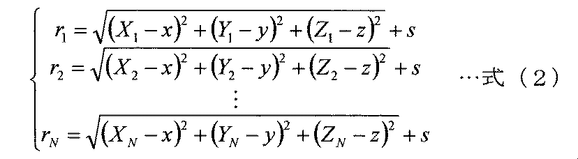
- the position s calculated by the above formula (2) and the like and the error s are taken into consideration, and the position is calculated by using a probabilistic model filter such as a Kalman filter to estimate the maximum likelihood position from the received signal.
- a probabilistic model filter such as a Kalman filter
- the distance from the own apparatus 101 to each satellite 120 (second satellite distance) is calculated.
- a distance error ⁇ 306 is calculated from the difference between the calculated distance and the distance (first satellite distance) 305 to the satellite calculated from the navigation signal from each satellite 120. That is, the distance error ⁇ i 306 of the i-th satellite position is defined as (Px, Py, Pz) as the own position obtained by the equation (2), and the position of the i-th satellite is (Xi, Yi, Zi), and when the distance to the i-th satellite (first satellite distance) 305 is r i , it is expressed by the following equation (3).
- the distance error ⁇ 306 of the satellite i calculated here is stored in the data storage device 105, and further transmitted to the other device 111 via the communication device 103 together with the satellite information 303 to 307 stored in the data storage device 105.
- the processing related to Steps 201, 202, 203, 204, 205, and 206 described above using the own device 101 is also executed in the other device 111 and stored in the data storage device 105 of the other device 111.
- information relating to the satellite used by the other device 111 for positioning in the data storage device 105 shown in FIG. 3, the satellite number 311, the satellite distance (third satellite distance) 312, and the distance error 313 are stored.
- the data storage device 105 of the other device 111 stores the number of other device information 309, the total number of satellites 310, the satellite number 311, the distance 312 to the satellite, and the distance error 313. Has been.
- the position estimation unit 106 of the own device 101 sends an end message to the satellite selection unit 107 and proceeds to step 207.
- step 204 if it is determined in step 204 that sufficient satellite information for positioning has not been accumulated, positioning of the own device 101 is impossible, and in step 206, the result of position unpositioning is output. Then, a message is sent to the relative position calculation unit 109, and the process proceeds to step 214.
- Steps 207 to 209 are processing of the satellite selection unit 107.
- step 207 it is determined whether the satellite information related to the satellite used by the other device 111 for positioning is received from the communication device 103. If it has been received, the process proceeds to step 208. If it has not been received, a message indicating that the satellite cannot be selected is sent to the relative position calculation unit 109, and the process proceeds to step 214.
- the communication device 103 of the own device 101 passively waits for communication from the other device 111, and data received via the communication device 103 is stored in the data storage device 105.
- the data of the other device 111 received by the own device 101 via the communication device 103 includes three or more satellite numbers 311 used for positioning by the other device 111 receiving the navigation signal and the three or more satellites 120. 312 and the distance error 313 are present as many as the number of satellites used by the other aircraft 111 for positioning.
- these data 311, 312, and 313 are stored in the data storage device 105 only (one set) used / calculated by the other device 111 in one positioning, and thereafter
- new data 311, 312, 313 used / calculated by the other device 111 is transmitted, the old data is deleted and the new data is recorded in the data storage device 105. That is, the data 311, 312, 313 related to the other device 111 of the data storage device 105 is rewritten for each set.
- the time measured based on the navigation signal received by the other device 111 (the time when the navigation signal was received may be) 314.
- the difference between the speed vector 316 and the attitude vector 317 of the other device 111 calculated at the time of the positioning and the mounting position of the signal receiving device (GPS receiver) 104 with respect to the vehicle body reference position of the other device 111 (GPS mounting position) 318 It is included.
- step 208 the satellite selection unit 107 reads all the satellite numbers 311 used for positioning by the other device 111 from the data storage device 105, sends a satellite selection completion message to the position correction unit 108, and proceeds to step 209.
- step 209 the satellite number 311 used for positioning by the other device 111 read in step 208 is compared with the satellite number 304 received by the own device 101, and the data 305 of the own device 101 relating to the satellite number that overlaps in both. , 306, 307 (satellite distance 305, distance error 306, satellite position 307) are read out, and the process proceeds to step 210. More specifically, in step 209, among the plurality of satellites 120, both the own aircraft 101 and the other aircraft 111 can receive the navigation signal, and are data related to the common satellite used for their own positioning, A distance 305 from 101 to each of the common satellites, a distance error 306 thereof, and a position 307 of each of the common satellites are read out. For example, in the example of FIG. 1, data 305, 306, and 307 related to three satellites 120a, 120b, and 120c are read out.
- Step 210 to step 212 are processing of the position correction unit 108.
- step 210 the position correction unit 108 determines whether or not the satellite distance 305, the distance error 306, and the satellite position 307 acquired in step 209 are sufficient for re-positioning of the own device 101 according to step 212 described later. . Whether or not repositioning is sufficient is determined based on whether or not data relating to three or more satellites 120 has been acquired in step 209, as in step 204. That is, if there are three or more overlapping satellite numbers in step 209, it is determined that positioning is sufficient. If the positioning is sufficient, the process proceeds to step 211. On the other hand, if the positioning is insufficient, a message is sent to the relative position calculation unit 109 and the process proceeds to step 214.
- step 211 the position correction unit 108 acquires the distance 312 and distance error 313 of the other aircraft 111 related to the overlapping satellite number in step 209 in addition to the satellite distance 305, distance error 306, and satellite position 307 acquired in step 209. Then, the process proceeds to step 212.
- step 212 the correction value Lci is calculated based on the information obtained in steps 209 and 211, and the position of the own device 101 is calculated again (repositioning of the own device 101).
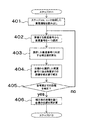
- the processing flow of recalculation of the position of the own device 101 using the satellite information of the other device 111 will be described in more detail with reference to FIG.
- step 401 all satellite information necessary for re-positioning is acquired, and the process proceeds to step 402.
- the satellite information acquired here includes the satellite information related to the satellite number duplicated in the other device 111 and the own device 101 acquired in step 209 and step 211 (specifically, the distance 305 from the own device 101 to each satellite, Distance error 306 and satellite position 307, and distance 312 and distance error 313) from other aircraft 111 to each satellite.
- the position correction unit 108 determines the satellite number i from the own aircraft 101 based on the distance errors 306 and 313 related to the n satellites and the distance errors 306 and 313 related to the satellite of the satellite number i selected in step 402.
- a correction value Lci used for correcting the distance ri305 to the satellite is calculated.
- the correction value Lci is common to the own device 101 and the other device 111, the distance error ⁇ ai 313 to the satellite i calculated by the other device 111, the distance error ⁇ si 306 to the satellite i calculated by the own device 101. Calculation is performed based on the following equation (4) from the number n of all satellites that have received the navigation signal.
- the correction value Lci of the distance ri305 from the own aircraft 101 to each of the n satellites 120 is calculated based on the distance from the other aircraft 111 to each of the n satellites 120. .
- the process proceeds to step 404.
- the distance error ⁇ ai may be calculated as the distance error ⁇ si and the distance error ⁇ si may be calculated as the distance error ⁇ ai in the following equation (4). .
- step 404 the distance is corrected by subtracting the correction value Lci acquired in step 403 from the distance 305ri from the satellite associated with the satellite number i selected in step 402 to the own aircraft 101.
- the distance from the satellite associated with the satellite number i to the own device 101 is corrected based on the distance from the satellite associated with the satellite number i to the other device 111.
- the process proceeds to step 405.
- step 405 it is confirmed whether or not all the satellite numbers acquired in step 401 have been processed from step 402 to 404. If the distance correction processing to the satellites related to all the satellite numbers has been completed, the process proceeds to step 406. If it has not been completed, the process returns to step 402 to repeat the processes of steps 402 to 404.
- step 406 positioning of the own device 101 is executed again using the corrected distance rmi obtained in the processing from step 401 to step 405.
- the relative position calculation unit 109 calculates the relative position between the own device 101 and the other device 111 based on the position of the own device 101 calculated again in Step 212 and the position 315 of the other device 111. calculate.
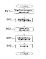
- an example of the relative position calculation processing flow executed in step 213 will be described in more detail with reference to FIG. In the example of FIG.
- the relative position calculation unit 109 calculates the position of the own device 101 calculated again in step 212, the reception time 308 of the own device acquired from the data storage device 105, the positioning time 314 of the other device, and the positioning Based on the position 315, the velocity vector 316, the attitude vector 317, and the GPS attachment position 318, the relative position between the own device 101 and the other device 111 is calculated.
- the relative position calculation unit 109 determines that the own device 101 is traveling from the known mounting position (GPS position) of the signal receiving device (GPS receiving device) 104 of the own device 101 in step 501. And the point obtained by projecting the position of the own device 101 recalculated in step 212 onto the plane is set as the new position of the own device 101.
- step 502 the positioning position 315, positioning time 314, speed vector 316, attitude vector 317, and GPS attachment position 318 of the other device 111 are acquired from the data storage device 105, and the process proceeds to step 503.
- step 503 the vector is extended in the direction of the attitude vector 317 starting from the positioning position 315 of the other device 111 acquired in step 502, and the point where the vector intersects the plane of step 501 is defined as the position on the plane of the other device 111. To do.
- step 504 a communication delay time is obtained from the difference between the reception time 308 of the own device 101 and the positioning time 314 of the other device 111 stored in the data storage device 105, and the delay time and the speed vector 316 of the other device 111 are obtained. Then, the moving direction and moving distance of the other device 111 during the delay time are calculated, and the moving distance is added to the plane position of the other device calculated in step 502 on the plane of step 501. Thereby, the position of the other device 111 at the reception time 308 of the own device 101 can be estimated. Here, the position of the other device 111 is calculated using the positioning time 314 of the other device 111. However, as described above, the navigation signal reception time of the other device 111 is used instead of the positioning time 314. May be.
- step 505 the relative position between the own device 101 and the other device 111 is calculated by taking the difference between the planar position of the own device 101 calculated in step 502 and the planar position of the other device 111 calculated in step 504. .
- the process proceeds to step 215.
- step 214 is a process executed when it is determined that the relative distance cannot be calculated in any of the determinations of step 204, step 207, and step 210.
- the relative position calculation unit 109 calculates the relative position. Is output that the calculation is impossible, and the process proceeds to step 215.
- step 215 it is determined whether or not the own device 101 is stopped. If the own device 101 is stopped, the processing of the relative position calculation device 102 is terminated. On the other hand, if the own device 101 is not stopped, the process returns to step 202 and the processes in and after step 202 are repeated.
- the method of calculating the relative position of the GPS by taking the difference between the GPS positions measured individually by the own aircraft and the other aircraft, all the GPS satellites used for both positioning The error caused by the error and the error caused by the GPS receiver are added to the relative position.
- the error caused by the satellite is corrected by using a common navigation satellite (GPS satellite) between the own aircraft and the other aircraft, Compared to the conventional method, the relative position between the own device and the other device can be calculated with higher accuracy.
- GPS satellite common navigation satellite
- the relative position is calculated based on the navigation signals from the satellites used for positioning in each of the own aircraft and the other aircraft (see, for example, FIG. 4).
- the relative position may be calculated based on the navigation signal from the satellite that has received the navigation signal. That is, a navigation signal that is not used for positioning may be used as long as it can be received by both the own device and the other device.
- the distance 312 and distance error 313 of the other device 111 used when calculating the relative position are only those related to the satellite used for positioning of the other device 111 (see steps 208 and 209).
- the relative position may be calculated using the distance 312 and the distance error 313 related to the satellite that could receive the navigation signal but was not used for the actual positioning of the other aircraft 111.
- the distance from the own device 101 to the satellite 120 is corrected with the correction value Lci as the distance from the other device 111 to the satellite 120.
- the correction value may be calculated based on either the distance from the other machine or the distance from the own machine.
- the correction value should be calculated based on which one of the satellites 120 is better viewed (that is, the distance 305 (312) between the own device 101 and the other device 111 and the distance). Some of them are selected based on the smaller error 306 (313) difference). If the correction value is calculated based on the better visibility of the satellite, the accuracy of the relative position can be improved than when the other value is used as a reference.
- satellite 101 related to all satellites from which other aircraft 111 was able to receive the navigation signal was received by own aircraft 101, and the work machine used as the reference for the correction value was changed according to the appearance of satellite 120.
- a second embodiment of the present invention for calculating the relative position will be described below.
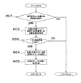
- FIG. 6 is a diagram showing only the changed part (the part replaced from step 207 to step 212 in FIG. 2) extracted from the processing of the relative position calculation apparatus 102 according to the second embodiment of the present invention. .
- Step 2 is executed.
- the satellite selection unit 107 receives a message indicating that the processing has been completed from the position estimation unit 106 in step 205, the processing of FIG. 6 is started.
- Steps 601 to 602 are processing of the satellite selection unit 107.
- the satellite selection unit 107 determines in step 601 whether satellite information relating to all satellites for which the other aircraft 111 has received the navigation signal from the communication device 103 has been received. If received, the process proceeds to step 602. On the other hand, if not received, a message indicating that the satellite cannot be selected is sent to the relative position calculation unit 109, and the process proceeds to step 214 (see FIG. 2).
- FIG. 7 is a diagram showing an example of the structure of data stored in the data storage device 105 of the own device 101 in the second embodiment of the present invention.
- the total number of satellites 701 is the total number of satellites from which the other aircraft 111 has received the navigation signal
- the satellite number 702 is the number of all satellites from which the other aircraft 111 has received the navigation signal.
- the distance 703 is the distance from the other aircraft 111 to all the satellites from which the other aircraft 111 has received the navigation signal
- the distance error 704 is the distance from the other aircraft 111 to all the satellites from which the other aircraft 111 has received the navigation signal. It is an error.
- the data storage device 105 also stores a positioning error 705 when the other device 111 performs positioning. Since the received and stored data other than the above are the same as the data shown in FIG. Note that the data storage device 105 of the other device 111 stores a device in which the own device and the other device are interchanged in FIG.
- the total number of satellites 701, the satellite number 702, the distance 703 to the satellite, the distance error 704, and the positioning error 705 of the data received via the communication device 103 are: Assume that only one set is stored, and the data in the data storage device 105 is rewritten for each set.
- the satellite selection unit 107 reads out the satellite numbers 702 related to all the satellites from which the other aircraft 111 has received the navigation signal from the data storage device 105. Then, the satellite number 702 is compared with the satellite number 304 received by the own device 101, and the data 305, 306, 307 (satellite distance 305, distance error 306, satellites) of the own device 101 relating to the satellite numbers that overlap in both. Position 307) and data 703, 704 (satellite distance 703, distance error 704) of the other aircraft 111 related to the overlapping satellite number are read, a satellite selection completion message is sent to the position correction unit 108, and the process proceeds to step 603. .
- Steps 603 to 606 are processing of the position correction unit 108.
- step 603 it is determined whether the information acquired in step 602 is sufficient for positioning based on whether there are three or more overlapping satellite numbers in step 602.
- step 604 the process proceeds to step 604
- step 214 the process proceeds to step 214.
- step 604 the own device 101 and the other device 111 perform a process of selecting the one with the better view of the satellite related to the overlapping satellite number in step 602. Specifically, the distance error 306 of the own device 101 calculated in step 205 is compared with the distance error 704 of the other device 111 stored in the data storage device 105, and the one with the smaller distance error is compared with the appearance of the satellite. Select which is better. The best way to get a job will be. The first one .. I ’m glad you know it is good .. I want you. _.... _ !. _! -___-..__
- a correction value Lci is calculated based on the dump truck selected in step 604 (hereinafter sometimes referred to as a selected dump truck), and the dump truck not selected in step 604 using the correction value Lci. Recalculate the position (hereinafter sometimes referred to as non-selected dump).
- the calculation of the correction value Lci in step 605 and the positioning calculation using the correction value Lci are performed in the same manner as the processing flow of FIG. 4 described above. Here, these calculations will be described with reference to FIG.
- step 801 all satellite information necessary for re-positioning is acquired, and the process proceeds to step 802.
- the satellite information acquired here is the satellite information related to the satellite number duplicated in the other device 111 and the own device 101 acquired in step 602.
- the position correcting unit 108 selects the dump truck selected in step 604 from the distance errors 306 and 704 related to the n satellites and the distance errors 306 and 704 related to the satellite of satellite number i selected in step 802.
- a correction value Lci used for correcting the distance ri from satellite to satellite number i is calculated.
- the correction value Lci is the distance error ⁇ ai from the selected dump to the satellite i, the distance error ⁇ si from the unselected dump to the satellite i, and all the satellites that have received the navigation signal in common with the own aircraft 101 and the other aircraft 111 From the number n, calculation is made based on the above equation (4).
- the correction value Lci of the distance ri from the non-selected dump to each of the n satellites 120 is calculated based on the selected dump by the above formula (4).
- the process proceeds to step 804.
- step 804 the correction value Lci acquired in step 803 is subtracted from the distance ri from the satellite associated with satellite number i selected in step 802 to the non-selected dump to correct the distance, and the process proceeds to step 805.
- step 805 it is checked whether all the satellite numbers acquired in step 801 have been processed from step 802 to 804. If the distance correction processing for all satellite numbers has been completed, the process proceeds to step 806. If it has not been completed, the process returns to step 802 to repeat the processes of steps 802 to 804.
- step 806 positioning of the non-selected dump is executed again using the corrected distance rmi obtained in the processing from step 801 to step 805.
- the corrected position of the non-selected dump (x, y, z) is a simultaneous expression of the above equation (5). It can be calculated by solving.
- the recalculation of the position of the non-selected dump is completed, the result is output and the process proceeds to step 213.
- step 213 the relative position calculation unit 109 calculates the relative position between the own device 101 and the other device 111 based on the position of the non-selected dump calculated again in step 605 and the position of the selected dump in the data storage device 105.
- the specific processing in step 213 may be performed by replacing “own device” with “non-selected dump” and “other device” with “selected dump” in the description of FIG. 5 of the first embodiment. Therefore, explanation is omitted here.
- the error caused by the satellite is corrected by using a common navigation satellite for the own aircraft and the other aircraft. Can be calculated with high accuracy.
- an example of a dump truck is given as the work machine.
- the type of the work machine to which the present invention can be applied is not limited to the dump truck.
- the present invention can be applied to any self-propelled working machine in which a receiving device capable of receiving a navigation signal from a navigation satellite such as a hydraulic excavator or a wheel loader can be mounted.
- the relative position calculation device 102 is mounted on a dump truck as a work machine, but the installation location is not limited.
- the relative position calculation device 102 is installed in the building of a control center that manages the operation status of a plurality of work machines, and the relative position calculation device 102 and the signal receiving device 104 and the data storage device 105 mounted on each work machine. May be configured to be capable of data communication.
- the present invention is not limited to the above-described embodiments, and includes various modifications within the scope not departing from the gist thereof.
- the present invention is not limited to the one having all the configurations described in the above embodiment, and includes a configuration in which a part of the configuration is deleted.
- a part of the configuration according to one embodiment can be added to or replaced with the configuration according to the other embodiment.
- each configuration related to the relative position calculation device 102, functions and execution processing of each configuration, etc. are partly or entirely hardware (for example, logic for executing each function is designed by an integrated circuit). It may be realized with.
- the configuration related to the relative position calculation device 102 may be a program (software) that realizes each function related to the configuration of the control device by being read and executed by the calculation processing device (for example, CPU).
- Information related to the program can be stored in, for example, a semiconductor memory (flash memory, SSD, etc.), a magnetic storage device (hard disk drive, etc.), a recording medium (magnetic disk, optical disc, etc.), and the like.
- control line and the information line are shown to be understood as necessary for the description of the embodiment, but all the control lines and information lines related to the product are not necessarily included. It does not always indicate. In practice, it can be considered that almost all the components are connected to each other.
Landscapes
- Engineering & Computer Science (AREA)
- Radar, Positioning & Navigation (AREA)
- Remote Sensing (AREA)
- Computer Networks & Wireless Communication (AREA)
- Physics & Mathematics (AREA)
- General Physics & Mathematics (AREA)
- Position Fixing By Use Of Radio Waves (AREA)
- Navigation (AREA)
Abstract
Description
まず、本発明の第1の実施の形態について図面を用いて説明する。第1の実施の形態に係る作業機械の相対位置演算システムは、作業機械として、主に鉱山で利用される複数の大型ダンプトラック(鉱山ダンプ)の相対位置を演算するものであり、相対位置を計算する前にはお互いの情報が無い場合の例である。




Claims (4)
- 複数の衛星の少なくとも1基から航法信号を受信する第1作業機械と、
前記複数の衛星の少なくとも1基から航法信号を受信する第2作業機械と、
前記複数の衛星のうち共通の衛星から前記第1作業機械と前記第2作業機械がそれぞれ受信した航法信号に基づいて、前記第1作業機械と前記第2作業機械の相対位置を算出する相対位置演算装置とを備えることを特徴とする作業機械の相対位置演算システム。 - 請求項1に記載の作業機械の相対位置演算システムにおいて、
前記共通の衛星は、前記複数の衛星のうち前記第1作業機械と前記第2作業機械の双方が航法信号を受信できた3基以上の衛星であり、
前記相対位置演算装置は、
前記複数の衛星から前記第1作業機械と前記第2作業機械が受信した航法信号に基づいて、前記第1作業機械の位置と前記第2作業機械の位置をそれぞれ算出し、
その算出結果に基づいて前記第1作業機械から前記共通の衛星のそれぞれまでの距離を補正して前記第1作業機械の位置を改めて算出し、
当該改めて算出した前記第1作業機械の位置と前記第2作業機械の位置から前記第1作業機械と前記第2作業機械の相対位置を算出する相対位置演算装置を備えることを特徴とする相対位置演算システム。 - 請求項2に記載の作業機械の相対位置演算システムにおいて、
前記相対位置演算装置は、
前記複数の衛星のいずれかから前記第1作業機械が受信した航法信号に基づいて、前記第1作業機械から当該航法信号を送信した衛星までの距離である第1衛星距離を算出し、
当該第1衛星距離と、前記第1作業機械が受信した前記航法信号を送信した衛星の位置とに基づいて、前記第1作業機械の位置を算出し、
当該第1作業機械の位置と、前記第1作業機械が受信した前記航法信号を送信した衛星の位置とに基づいて、前記第1作業機械から当該航法信号を送信した衛星までの距離である第2衛星距離を算出し、
前記複数の衛星のいずれかから前記第2作業機械が受信した航法信号に基づいて、前記第2作業機械から当該航法信号を送信した衛星までの距離である第3衛星距離を算出し、
当該第3衛星距離と、前記第2作業機械が受信した前記航法信号を送信した衛星の位置とに基づいて、前記第2作業機械の位置を算出し、
当該第2作業機械の位置と、前記第2作業機械が受信した前記航法信号を送信した衛星の位置とに基づいて、前記第2作業機械から当該航法信号を送信した衛星までの距離である第4衛星距離を算出し、
前記第1衛星距離と前記第2衛星距離の差分と、前記第3衛星距離と前記第4衛星距離の差分とに基づいて、前記第2作業機械を基準とした前記第1衛星距離の補正値を算出し、
当該第1衛星距離の補正値と、前記第1衛星距離に基づいて、前記第1作業機械の位置を改めて算出し、
当該改めて算出した前記第1作業機械の位置と、前記第2作業機械の位置とから、前記第1作業機械と前記第2作業機械の相対位置を算出することを特徴とする作業機械の相対位置演算システム。 - 請求項3に記載の作業機械の相対位置演算システムにおいて、
前記第3衛星距離と前記第4衛星距離の差分は、前記第1衛星距離と前記第2衛星距離の差分よりも小さいことを特徴とする作業機械の相対位置演算システム。
Priority Applications (6)
| Application Number | Priority Date | Filing Date | Title |
|---|---|---|---|
| AU2014297425A AU2014297425A1 (en) | 2013-07-29 | 2014-07-25 | Relative position computation system for working machine |
| US14/772,920 US9766350B2 (en) | 2013-07-29 | 2014-07-25 | Relative position calculating system for work machine |
| JP2015529556A JP6230605B2 (ja) | 2013-07-29 | 2014-07-25 | 作業機械の相対位置演算システム |
| CA2903959A CA2903959C (en) | 2013-07-29 | 2014-07-25 | Relative position calculating system for work machine |
| AU2017201336A AU2017201336A1 (en) | 2013-07-29 | 2017-02-27 | Relative position computation system for working machine |
| AU2017201332A AU2017201332A1 (en) | 2013-07-29 | 2017-02-27 | Relative position computation system for working machine |
Applications Claiming Priority (2)
| Application Number | Priority Date | Filing Date | Title |
|---|---|---|---|
| JP2013-156409 | 2013-07-29 | ||
| JP2013156409 | 2013-07-29 |
Publications (1)
| Publication Number | Publication Date |
|---|---|
| WO2015016159A1 true WO2015016159A1 (ja) | 2015-02-05 |
Family
ID=52431694
Family Applications (1)
| Application Number | Title | Priority Date | Filing Date |
|---|---|---|---|
| PCT/JP2014/069765 Ceased WO2015016159A1 (ja) | 2013-07-29 | 2014-07-25 | 作業機械の相対位置演算システム |
Country Status (5)
| Country | Link |
|---|---|
| US (1) | US9766350B2 (ja) |
| JP (1) | JP6230605B2 (ja) |
| AU (3) | AU2014297425A1 (ja) |
| CA (1) | CA2903959C (ja) |
| WO (1) | WO2015016159A1 (ja) |
Cited By (2)
| Publication number | Priority date | Publication date | Assignee | Title |
|---|---|---|---|---|
| JP2018124096A (ja) * | 2017-01-30 | 2018-08-09 | 学校法人電子開発学園 | 情報処理システム、情報処理装置、情報処理方法及びプログラム |
| EP3353615A4 (en) * | 2015-09-15 | 2019-04-10 | Peloton Technology Inc. | VEHICLE IDENTIFICATION AND LOCALIZATION USING SENSOR FUSION AND COMMUNICATION BETWEEN VEHICLES |
Families Citing this family (3)
| Publication number | Priority date | Publication date | Assignee | Title |
|---|---|---|---|---|
| JP5607841B1 (ja) * | 2013-07-30 | 2014-10-15 | 株式会社小松製作所 | 鉱山機械の管理システム及び管理方法 |
| WO2021064775A1 (ja) * | 2019-09-30 | 2021-04-08 | 日立建機株式会社 | 作業機械 |
| US20220365536A1 (en) * | 2021-05-13 | 2022-11-17 | Deere & Company | Real-time surface scanning and estimation of ground characteristics for ground compacting work machines |
Citations (5)
| Publication number | Priority date | Publication date | Assignee | Title |
|---|---|---|---|---|
| JPH10148665A (ja) * | 1996-11-19 | 1998-06-02 | Matsushita Electric Ind Co Ltd | 車車間通信による相対位置算出装置 |
| JPH11295411A (ja) * | 1998-04-15 | 1999-10-29 | Mitsubishi Electric Corp | Dgps位置標定システム |
| JP2000304843A (ja) * | 1999-04-22 | 2000-11-02 | Fujitsu Ltd | Gps測位装置およびgps測位方法ならびにgps測位プログラムを記録したコンピュータ読み取り可能な記録媒体 |
| JP2004170268A (ja) * | 2002-11-20 | 2004-06-17 | Alpine Electronics Inc | 車両位置検出方法および装置 |
| JP2011106870A (ja) * | 2009-11-13 | 2011-06-02 | Toyota Motor Corp | 相対位置算出装置 |
Family Cites Families (4)
| Publication number | Priority date | Publication date | Assignee | Title |
|---|---|---|---|---|
| JPH112675A (ja) * | 1997-06-13 | 1999-01-06 | Mitsubishi Electric Corp | 相対位置検出システムおよび相対位置検出装置 |
| JP3721964B2 (ja) | 2000-09-12 | 2005-11-30 | 三菱電機株式会社 | Gps受信装置 |
| JP4463757B2 (ja) | 2005-12-09 | 2010-05-19 | 株式会社小松製作所 | 車両の走行制御装置 |
| JP5585177B2 (ja) | 2010-04-12 | 2014-09-10 | トヨタ自動車株式会社 | 先行車位置判定装置 |
-
2014
- 2014-07-25 WO PCT/JP2014/069765 patent/WO2015016159A1/ja not_active Ceased
- 2014-07-25 JP JP2015529556A patent/JP6230605B2/ja active Active
- 2014-07-25 AU AU2014297425A patent/AU2014297425A1/en not_active Abandoned
- 2014-07-25 CA CA2903959A patent/CA2903959C/en active Active
- 2014-07-25 US US14/772,920 patent/US9766350B2/en active Active
-
2017
- 2017-02-27 AU AU2017201336A patent/AU2017201336A1/en not_active Abandoned
- 2017-02-27 AU AU2017201332A patent/AU2017201332A1/en not_active Abandoned
Patent Citations (5)
| Publication number | Priority date | Publication date | Assignee | Title |
|---|---|---|---|---|
| JPH10148665A (ja) * | 1996-11-19 | 1998-06-02 | Matsushita Electric Ind Co Ltd | 車車間通信による相対位置算出装置 |
| JPH11295411A (ja) * | 1998-04-15 | 1999-10-29 | Mitsubishi Electric Corp | Dgps位置標定システム |
| JP2000304843A (ja) * | 1999-04-22 | 2000-11-02 | Fujitsu Ltd | Gps測位装置およびgps測位方法ならびにgps測位プログラムを記録したコンピュータ読み取り可能な記録媒体 |
| JP2004170268A (ja) * | 2002-11-20 | 2004-06-17 | Alpine Electronics Inc | 車両位置検出方法および装置 |
| JP2011106870A (ja) * | 2009-11-13 | 2011-06-02 | Toyota Motor Corp | 相対位置算出装置 |
Cited By (2)
| Publication number | Priority date | Publication date | Assignee | Title |
|---|---|---|---|---|
| EP3353615A4 (en) * | 2015-09-15 | 2019-04-10 | Peloton Technology Inc. | VEHICLE IDENTIFICATION AND LOCALIZATION USING SENSOR FUSION AND COMMUNICATION BETWEEN VEHICLES |
| JP2018124096A (ja) * | 2017-01-30 | 2018-08-09 | 学校法人電子開発学園 | 情報処理システム、情報処理装置、情報処理方法及びプログラム |
Also Published As
| Publication number | Publication date |
|---|---|
| CA2903959C (en) | 2017-10-24 |
| JP6230605B2 (ja) | 2017-11-15 |
| US9766350B2 (en) | 2017-09-19 |
| US20160018531A1 (en) | 2016-01-21 |
| JPWO2015016159A1 (ja) | 2017-03-02 |
| AU2017201336A1 (en) | 2017-03-16 |
| AU2014297425A1 (en) | 2015-09-24 |
| AU2017201332A1 (en) | 2017-03-16 |
| CA2903959A1 (en) | 2015-02-05 |
Similar Documents
| Publication | Publication Date | Title |
|---|---|---|
| JP4192940B2 (ja) | 移動体用位置推定装置 | |
| JP6230605B2 (ja) | 作業機械の相対位置演算システム | |
| US9064352B2 (en) | Position identification system with multiple cross-checks | |
| JP6671152B2 (ja) | 自己位置推定装置の異常検知装置及び車両 | |
| JP6395771B2 (ja) | 車両位置検出装置、自動操舵制御装置、車両位置検出方法および自動操舵制御方法 | |
| US20140180579A1 (en) | Machine positioning system utilizing position error checking | |
| KR102553590B1 (ko) | 작업 기계 | |
| JP2015191341A (ja) | 車両走行システム及び運行管理サーバ | |
| JP2015138418A (ja) | 地図生成システム | |
| CN111949030B (zh) | 一种农机定位方法、农机车辆和存储介质 | |
| JP2017531781A (ja) | 駐車施設内におけるセンサー校正 | |
| CN112424642A (zh) | 移动体定位系统和移动体定位方法 | |
| US10024977B1 (en) | Low speed heading measurement | |
| JPWO2017022019A1 (ja) | 走行制御装置の制御方法および走行制御装置 | |
| US20160116289A1 (en) | Positioning system implementing multi-sensor pose solution | |
| KR20220143762A (ko) | 작업 기계의 측위 시스템, 작업 기계 및 작업 기계의 측위 방법 | |
| CN113465590B (zh) | 路径规划方法和装置、自动驾驶方法和装置及作业机械 | |
| JP6539129B2 (ja) | 自車位置推定装置、及びそれを用いた操舵制御装置、並びに自車位置推定方法 | |
| CN104034338A (zh) | 一种动态导航方法及装置 | |
| EP3913146B1 (en) | Work machine with collision mitigation system | |
| CN116519018B (zh) | 车载低成本嵌入式组合导航安装角误差在线估计方法、系统及介质 | |
| US9128183B2 (en) | Machine navigation system utilizing scale factor adjustment | |
| JP2017129380A (ja) | 判断装置、判断方法、判断プログラム及び記録媒体 | |
| CN114279440B (zh) | Imu定位的管理方法、装置和车载地图系统 | |
| CN113514068A (zh) | 作业机械定位方法、装置及作业机械 |
Legal Events
| Date | Code | Title | Description |
|---|---|---|---|
| 121 | Ep: the epo has been informed by wipo that ep was designated in this application |
Ref document number: 14831237 Country of ref document: EP Kind code of ref document: A1 |
|
| ENP | Entry into the national phase |
Ref document number: 2903959 Country of ref document: CA |
|
| WWE | Wipo information: entry into national phase |
Ref document number: 14772920 Country of ref document: US |
|
| ENP | Entry into the national phase |
Ref document number: 2014297425 Country of ref document: AU Date of ref document: 20140725 Kind code of ref document: A |
|
| ENP | Entry into the national phase |
Ref document number: 2015529556 Country of ref document: JP Kind code of ref document: A |
|
| NENP | Non-entry into the national phase |
Ref country code: DE |
|
| 122 | Ep: pct application non-entry in european phase |
Ref document number: 14831237 Country of ref document: EP Kind code of ref document: A1 |