WO2015016158A1 - 発泡成形部材の製造方法および衝撃吸収部材 - Google Patents
発泡成形部材の製造方法および衝撃吸収部材 Download PDFInfo
- Publication number
- WO2015016158A1 WO2015016158A1 PCT/JP2014/069760 JP2014069760W WO2015016158A1 WO 2015016158 A1 WO2015016158 A1 WO 2015016158A1 JP 2014069760 W JP2014069760 W JP 2014069760W WO 2015016158 A1 WO2015016158 A1 WO 2015016158A1
- Authority
- WO
- WIPO (PCT)
- Prior art keywords
- molded body
- molded
- foam
- rigid plate
- mold
- Prior art date
Links
Images


Classifications
-
- B—PERFORMING OPERATIONS; TRANSPORTING
- B29—WORKING OF PLASTICS; WORKING OF SUBSTANCES IN A PLASTIC STATE IN GENERAL
- B29C—SHAPING OR JOINING OF PLASTICS; SHAPING OF MATERIAL IN A PLASTIC STATE, NOT OTHERWISE PROVIDED FOR; AFTER-TREATMENT OF THE SHAPED PRODUCTS, e.g. REPAIRING
- B29C44/00—Shaping by internal pressure generated in the material, e.g. swelling or foaming ; Producing porous or cellular expanded plastics articles
- B29C44/02—Shaping by internal pressure generated in the material, e.g. swelling or foaming ; Producing porous or cellular expanded plastics articles for articles of definite length, i.e. discrete articles
- B29C44/022—Foaming unrestricted by cavity walls, e.g. without using moulds or using only internal cores
-
- B—PERFORMING OPERATIONS; TRANSPORTING
- B29—WORKING OF PLASTICS; WORKING OF SUBSTANCES IN A PLASTIC STATE IN GENERAL
- B29C—SHAPING OR JOINING OF PLASTICS; SHAPING OF MATERIAL IN A PLASTIC STATE, NOT OTHERWISE PROVIDED FOR; AFTER-TREATMENT OF THE SHAPED PRODUCTS, e.g. REPAIRING
- B29C44/00—Shaping by internal pressure generated in the material, e.g. swelling or foaming ; Producing porous or cellular expanded plastics articles
- B29C44/02—Shaping by internal pressure generated in the material, e.g. swelling or foaming ; Producing porous or cellular expanded plastics articles for articles of definite length, i.e. discrete articles
- B29C44/12—Incorporating or moulding on preformed parts, e.g. inserts or reinforcements
- B29C44/1271—Incorporating or moulding on preformed parts, e.g. inserts or reinforcements the preformed parts being partially covered
-
- B—PERFORMING OPERATIONS; TRANSPORTING
- B29—WORKING OF PLASTICS; WORKING OF SUBSTANCES IN A PLASTIC STATE IN GENERAL
- B29C—SHAPING OR JOINING OF PLASTICS; SHAPING OF MATERIAL IN A PLASTIC STATE, NOT OTHERWISE PROVIDED FOR; AFTER-TREATMENT OF THE SHAPED PRODUCTS, e.g. REPAIRING
- B29C44/00—Shaping by internal pressure generated in the material, e.g. swelling or foaming ; Producing porous or cellular expanded plastics articles
- B29C44/02—Shaping by internal pressure generated in the material, e.g. swelling or foaming ; Producing porous or cellular expanded plastics articles for articles of definite length, i.e. discrete articles
- B29C44/12—Incorporating or moulding on preformed parts, e.g. inserts or reinforcements
- B29C44/1285—Incorporating or moulding on preformed parts, e.g. inserts or reinforcements the preformed part being foamed
-
- B—PERFORMING OPERATIONS; TRANSPORTING
- B60—VEHICLES IN GENERAL
- B60R—VEHICLES, VEHICLE FITTINGS, OR VEHICLE PARTS, NOT OTHERWISE PROVIDED FOR
- B60R21/00—Arrangements or fittings on vehicles for protecting or preventing injuries to occupants or pedestrians in case of accidents or other traffic risks
- B60R21/02—Occupant safety arrangements or fittings, e.g. crash pads
- B60R21/04—Padded linings for the vehicle interior ; Energy absorbing structures associated with padded or non-padded linings
-
- F—MECHANICAL ENGINEERING; LIGHTING; HEATING; WEAPONS; BLASTING
- F16—ENGINEERING ELEMENTS AND UNITS; GENERAL MEASURES FOR PRODUCING AND MAINTAINING EFFECTIVE FUNCTIONING OF MACHINES OR INSTALLATIONS; THERMAL INSULATION IN GENERAL
- F16F—SPRINGS; SHOCK-ABSORBERS; MEANS FOR DAMPING VIBRATION
- F16F7/00—Vibration-dampers; Shock-absorbers
- F16F7/12—Vibration-dampers; Shock-absorbers using plastic deformation of members
-
- B—PERFORMING OPERATIONS; TRANSPORTING
- B29—WORKING OF PLASTICS; WORKING OF SUBSTANCES IN A PLASTIC STATE IN GENERAL
- B29L—INDEXING SCHEME ASSOCIATED WITH SUBCLASS B29C, RELATING TO PARTICULAR ARTICLES
- B29L2031/00—Other particular articles
- B29L2031/30—Vehicles, e.g. ships or aircraft, or body parts thereof
- B29L2031/3002—Superstructures characterized by combining metal and plastics, i.e. hybrid parts
-
- B—PERFORMING OPERATIONS; TRANSPORTING
- B29—WORKING OF PLASTICS; WORKING OF SUBSTANCES IN A PLASTIC STATE IN GENERAL
- B29L—INDEXING SCHEME ASSOCIATED WITH SUBCLASS B29C, RELATING TO PARTICULAR ARTICLES
- B29L2031/00—Other particular articles
- B29L2031/30—Vehicles, e.g. ships or aircraft, or body parts thereof
- B29L2031/3044—Bumpers
-
- B—PERFORMING OPERATIONS; TRANSPORTING
- B29—WORKING OF PLASTICS; WORKING OF SUBSTANCES IN A PLASTIC STATE IN GENERAL
- B29L—INDEXING SCHEME ASSOCIATED WITH SUBCLASS B29C, RELATING TO PARTICULAR ARTICLES
- B29L2031/00—Other particular articles
- B29L2031/58—Upholstery or cushions, e.g. vehicle upholstery or interior padding
Definitions
- the present invention relates to a method for producing a foam molded member and an impact absorbing member.
- An impact absorbing member formed of a foam molded member such as rigid polyurethane foam is attached to an automobile door for absorbing impact energy at the time of a side collision.
- an impact absorbing member having a structure in which a foam molded member is bonded to one side of a rigid member such as an iron plate.
- Japanese Patent Application Laid-Open No. 2011-121485 describes a configuration in which a foam molded member is formed on both sides of an iron plate by providing a through hole in the iron plate and a structure in which a foam molded resin wraps around.
- the present invention aims to accurately form a foam molded member on both surfaces of a rigid plate.
- the method for producing a foam molded member according to the first aspect of the present invention includes a first step of placing a foam molded first molded body and a rigid plate in a mold, and injecting a foam material into the mold. And a second step of foam-molding a second molded body that wraps a part of the rigid plate and is integrated with the first molded body.
- the first molded body and the rigid plate that are foam-molded are arranged in a mold, and the second molded body is foam-molded by injecting a foam material into the second-stage foaming.
- a step of attaching the first molded body and the second molded body to the rigid plate becomes unnecessary.
- the position shift which is a relative attachment error of a 1st molded object, a 2nd molded object, and a rigid board can be suppressed in the state arrange
- the foam molded member manufacturing method according to the second aspect is arranged in the mold by providing a gap between the first molded body and the rigid plate, and in the second step, The foam material is allowed to enter the gap, and a part of the rigid plate is wrapped with the second molded body, and the first molded body and the second molded body are bonded together.
- the rigid plate can be wrapped with the second molded body and bonded to the first molded body.
- the rigid plate in the second step, is arranged so that a gap is formed between the inner wall of the mold and the peripheral edge of the rigid plate.
- the foam material can flow without resistance from the gap into the gap between the rigid plate and the first molded body.
- the rigid plate in which a through hole is formed is used, and the foam material is caused to enter the gap from the through hole.
- the foam material can flow without resistance from the through hole into the gap between the rigid plate and the first molded body.
- a part of the rigid plate is pressed against the inner surface of the molding die, and the part between the rigid plate and the molding die is pressed. It arrange
- an exposed surface of a rigid plate on which the molded body is not foam molded can be formed.
- the shock absorbing member according to the sixth aspect includes a first molded body foam-molded on a part of one surface of the rigid plate, and a second molded body foam-molded on the entire other surface of the rigid plate; Have.
- This impact absorbing member can absorb the impact force in two stages of the first molded body and the second molded body. After the first molded body absorbs the impact and is crushed, the impact can be absorbed while maintaining a certain posture by transmitting the force to the second molded body through the rigid plate.
- the impact absorbing member according to the seventh aspect is molded from a different type of foam material than the first molded body and the second molded body.
- this shock absorbing member when the impact force is absorbed in two stages of the first molded body and the second molded body, one can be more easily crushed than the other, thereby increasing the range of impact that can be absorbed.
- a through hole is provided in a portion of the rigid plate sandwiched between the first molded body and the second molded body.
- the foam molded member since the second molded body and the first molded body are integrated with each other through the through hole of the rigid plate at the time of foam molding, the foam molded member may be structured not to be displaced in the surface direction of the rigid plate. it can.
- the diameter of the through hole is 10 to 20 mm.
- the foam material can pass without resistance during foam molding, and the strength of the rigid plate can be maintained.
- the foam material can pass without resistance during foam molding, and the strength of the rigid plate can be maintained.
- the impact absorbing member according to an eleventh aspect is configured such that, in the second molded body, the second molded body includes the first molded body and the rigid body by a foam material that wraps around the rigid plate toward the first molded body side. Bonded to the board.
- the second molded body can be formed integrally with the first molded body during foam molding.
- the foam molded member can be accurately formed on both surfaces of the rigid plate.
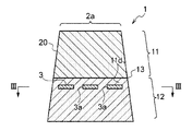
- FIG. 2 is a cross-sectional view of the foam molded member shown in FIG. 1 as seen from line II-II.
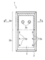
- FIG. 3 is a cross-sectional view of the second part of the foam-molded member shown in FIG. 1 as seen from line III-III in FIG.
- FIG. 5 is a cross-sectional view of the second partial molding die relating to the production of the foam molded member shown in FIG. 1 as seen from line VV in FIG. 1.
- FIG. 3 is a cross-sectional view of the second partial molding die relating to the production of the foam molded member shown in FIG. 1 as viewed from the first part side along the line III-III in FIG. 2.
- FIG. 7 is a cross-sectional view of the second partial molding die related to the production of the foam molded member shown in FIG. 1 as seen from the line VII-VII in FIG. 4.
- FIG. 5 is a cross-sectional view of a second partial molding die showing a method for manufacturing the foam molded member shown in FIG. 1 as seen from line VV in FIG. 1.
- FIG. 8 is a cross-sectional view showing a step following FIG. 7 in the method for manufacturing the foam molded member shown in FIG. 7. It is sectional drawing which shows the process of following FIG. 8 in the manufacturing method of the foaming molding member shown in FIG.
- an impact absorbing member (hereinafter abbreviated as EA material) attached to the door of an automobile is exemplified as the foam molded member. It is applicable also to the manufacturing method.
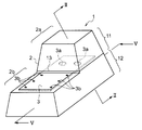
- FIG. 1 is a perspective view of an EA material 1 (impact absorbing member) as a foam molded member according to an embodiment
- FIGS. 2 and 3 are cross-sectional views of the EA material 1, respectively.
- 2 is a cross-sectional view taken along line II-II in FIGS. 1 and 3
- FIG. 3 is a cross-sectional view taken along line III-III in FIG. 4 to 9 are cross-sectional views of a mold (a metal mold is preferably used, but other materials may be used) showing a method of manufacturing the EA material 1.
- 4, 7 to 9 each show a cross section of the portion along the line VV in FIG. 5
- FIG. 5 shows a cross section of the portion along the line VI-VI in FIG. 4
- FIG. The cross section of the part which follows the VII-VII line of is shown.
- the lower surface of the EA material 1 in FIGS. 1 and 2 faces the inner surface of the door when the EA material 1 is mounted in the door.
- the door inner surface side (lower side in FIGS. 1 and 2) of the EA material 1 is referred to as a base end side
- the side opposite to the door trim (upper side in FIGS. 1 and 2) is referred to as a distal end side.
- the direction from the base end side to the front end side (or the opposite direction) is referred to as the thickness direction.
- the EA material 1 includes an EA material body 2 as a foam molded member obtained by foaming a synthetic resin material such as hard polyurethane, and a rigid member 3 as an embedded member in which at least a part is embedded in the EA material body 2. And have.
- the EA material main body 2 includes a large thickness portion 2a having a large thickness (size from the base end side to the distal end side) and a small thickness portion 2b having a thickness smaller than that of the large thickness portion 2a.
- the large thickness portion 2 a and the small thickness portion 2 b are disposed adjacent to each other in the direction orthogonal to the thickness direction.
- the adjacent direction of the large thickness portion 2a and the small thickness portion 2b is referred to as the longitudinal direction of the EA material main body 2
- the direction orthogonal to both the longitudinal direction and the thickness direction is referred to as the width direction of the EA material main body 2. .
- FIG. 1 the adjacent direction of the large thickness portion 2a and the small thickness portion 2b is referred to as the longitudinal direction of the EA material main body 2
- the width direction of the EA material main body 2 is referred to as the width direction of the EA material main body 2.
- the large-thickness portion 2a and the small-thickness portion 2b have end surfaces on the base end side (hereinafter referred to as the base end surface) that are substantially in the same plane.
- the end surface (hereinafter referred to as the front end surface) of the large thickness portion 2a recedes from the front end side to the base end side.
- the shape of the EA material body 2 is not limited to this.
- the rigid member 3 is a metal plate material arranged across the large thickness portion 2a and the small thickness portion 2b, and a part thereof While being embedded in the large thickness portion 2a, other portions are embedded in the small thickness portion 2b, and a part of the surface is exposed.
- the rigid member 3 has a flat plate shape, and the plate surfaces thereof are arranged so as to be substantially parallel to both front end surfaces of the large thickness portion 2a and the small thickness portion 2b. ing.
- a part of the rigid member 3 is arranged so as to cover the tip surface of the small thickness portion 2b, and the inside of the small thickness portion 2b is substantially equal to the thickness.
- the plate surface of the rigid member 3 (hereinafter referred to as the tip side plate surface) is exposed at the tip surface of the small thickness portion 2b.
- the exposed distal end side plate surface of the rigid member 3 and the distal end surface of the small thickness portion 2b are substantially flush.
- the arrangement of the rigid member 3 is not limited to this. For example, at least a part of the front end side plate surface is covered with the foamed synthetic resin constituting the small thickness portion 2b. It may be embedded.
- a part of the rigid member 3 is embedded in the middle of the large thickness portion 2a in the thickness direction.
- a through hole 3a that penetrates the rigid member 3 in the thickness direction is provided on the side of the rigid member 3 embedded in the large thickness portion 2a.
- the second portion synthetic resin raw material U (foamed material) supplied to the base end side (second portion 12 described later) of the thicker portion 2a than the rigid member 3 penetrates this. It is also supplied to the distal end side (the first portion 11 side described later) of the large thickness portion 2a through the hole 3a. Further, the second portion synthetic resin raw material U supplied to the distal end side of the thick portion 2a and foamed from the rigid member 3 expands to the proximal end side of the thick portion 2a through the through hole 3a.
- two through holes 3 a are provided in the portion embedded in the large thickness portion 2 a of the rigid member 3 at intervals in the width direction of the EA material body 2.
- the number and arrangement of the through holes 3a are not limited to this.
- the opening shape of the through hole 3a is circular, but the opening shape of the through hole 3a is not limited to this.
- each penetration it is desirable that the diameter of the hole 3a and the number per unit area be within the following ranges.
- the diameter of the through hole 3a is desirably in the range of 10 to 20 mm, and more preferably in the range of 12 to 15 mm.
- the inventors have found from experiments that the strength of the rigid member 3 is reduced if it is larger than this, and that the synthetic resin raw material U for the second portion may not sufficiently pass through without resistance if it is smaller.
- the number of the through holes 3a is desirably 2 to 10 per 10000 mm 2 of the plate surface of the rigid member 3, and is preferably provided in the range of 5 to 7. If it is more than this, the strength of the rigid member 3 is lowered, and if it is less, there is a possibility that the second portion synthetic resin raw material U will not pass through without sufficient resistance.
- the interval between adjacent through holes 3a is preferably in the range of 10 to 70 mm, and more preferably in the range of 30 to 50 mm. If it is closer than this, the strength of the rigid member 3 is lowered, and if it is far, there is a possibility that the second portion synthetic resin raw material U will not pass through without sufficient resistance.
- the outer peripheral edge of the rigid member 3 is not exposed and is embedded in the EA material main body 2.
- the outer peripheral edge may be exposed without being embedded.
- the rigid member 3 when the rigid member 3 is arranged in the mold 20 as an example of the molding die in the arrangement step described later, an example of the outer peripheral edge of the rigid member 3 and the inner wall of the mold 20 are shown.
- a gap 11e shown in FIGS. 5 and 6 is formed between the inner surface of the cavity.
- the second part synthetic resin raw material U before and after foaming passes through the gap 11e from the proximal end side to the distal end side of the thicker portion 2a than the rigid member 3, or its On the contrary, it can flow.
- the side peripheral surface of the EA material body 2 is formed with the foamed synthetic resin.
- the gap 11e between the outer peripheral edge of the rigid member 3 and the inner surface of the cavity of the mold 20 in a state where the rigid member 3 is disposed in the mold 20 is in the range of 5 to 50 mm, and particularly in the range of 10 to 20 mm. It is preferable.
- a small hole 3 b is provided on the small thickness portion 2 b side of the rigid member 3.
- the small hole 3b is desirably a through hole penetrating the rigid member 3, but may be a non-penetrating recess.
- the diameter of each small hole 3b is preferably 1 to 10 mm, particularly 2 to 5 mm.
- three small circular holes 3b are provided along both side edges of the rigid member 3, but the shape, number and arrangement of the small holes 3b are not particularly limited.
- the constituent material of the rigid member 3 includes steel plates such as iron plates and aluminum plates, resin plates, etc., and iron plates are particularly preferably used.
- the thickness of the rigid member 3 is preferably in the range of 0.3 to 5.0 mm, and more preferably in the range of 0.6 to 1.6 mm.
- the configuration and arrangement of the rigid member 3 are not limited to this.
- the through hole 3 a may not be provided in the rigid member 3, for example, a notch may be provided in the peripheral portion, or a part of the end face may be pressed against the cavity inner surface.
- the second portion synthetic resin raw material U may not enter between a part of the end surface and the cavity inner surface.
- the second partial synthetic resin raw material U may be caused to flow through the gap 11e between the outer peripheral edge of the rigid member 3 and the cavity inner surface of the mold 20.
- the outer peripheral edge of the rigid member 3 may be at least partially exposed on the side peripheral surface of the EA material main body 2.
- a part of the rigid member 3 may extend outward from the EA material body 2.
- the rigid member 3 may have a shape other than a flat plate shape.
- a portion of the EA material body 2 on the tip side of the middle portion in the thickness direction of the large thickness portion 2a is an example of a first molded body prepared by a first partial preparation step described later. This is the first part 11.
- a second portion 12 is formed.
- the first portion 11 and the second portion 12 are adjacent to each other, and are welded by the second portion synthetic resin raw material U coming into contact with the first portion 11 in the second portion molding step.
- 1 and 2 indicates a boundary portion between the first portion 11 and the second portion 12.
- the first portion 11 has a larger thickness portion 2a than the rigid member 3 embedded in the larger thickness portion 2a.
- This part is composed. That is, the rigid member 3 is not embedded in the first portion 11 and is separated by a predetermined interval. This interval is preferably about 0.5 to 10 mm, but is 5 mm in this embodiment.
- the rigid member 3 is embedded in the second portion 12 in the vicinity of the boundary between the first portion 11 and the second portion 12 as a whole.
- the fraction structure of the 1st part 11 and the 2nd part 12 is not limited to this.
- the second part synthetic resin raw material U supplied to the second part 12 side from the rigid member 3 is the gap between the through hole 3 a and the rigid member 3 and the cavity inner surface of the mold 20. 11e passes around the first portion 11 side of the rigid member 3 as well.
- the internal shape of the cavity is a shape corresponding to the entire external shape of the EA material body 2.
- the mold 20 includes a lower mold 21 and an upper mold 22.
- die 20 may have a core etc. as needed.
- the lower die 21 mainly constitutes a cavity bottom surface and a side peripheral surface
- the upper die 22 mainly constitutes a cavity ceiling surface.
- the EA material body 2 is molded with its tip side facing downward.
- the front end surface of the EA material body 2 is molded by the cavity bottom surface of the lower mold 21, the side circumferential surface of the EA material body 2 is molded by the cavity side circumferential surface of the lower mold 21, and the EA is formed by the cavity ceiling surface of the upper mold 22.
- the base end surface of the material main body 2 is molded.
- a relatively deep large depth portion 21a corresponding to the large thickness portion 2a of the EA material main body 2 and a large depth portion 21a corresponding to the small thickness portion 2b of the EA material main body 2 Shallow shallow depth portion 21b.
- the space from the middle in the depth direction of the large depth portion 21 a (position slightly lower than the bottom surface of the small depth portion 21 b) to the bottom surface is the first portion of the EA material main body 2.
- 11 is a first part-corresponding space in which the space extending from the bottom surface of the small depth part 21b to the inside of the large depth part 21a (above the first part 11) at the same depth is embedded in the EA material body 2.
- the space corresponding to the rigid member 3 is provided.
- a fastening tool 23 such as a magnet for fastening the rigid member 3 disposed on the bottom surface may be provided on the bottom surface of the small depth portion 21b.
- the fastener 23 is not limited to a magnet.
- the remaining space in the cavity of the mold 20 is a second part corresponding space in which the second part 12 of the EA material body 2 is formed.
- the synthetic resin raw material for 1st part which comprises the 1st part 11 may have the same mixing
- the foam molding of the first part 11 is performed separately from the second part 12 in advance.
- the molding of the first portion 11 can be performed by the same method as the molding of a general single foam molded member.
- the mold used for molding the first portion 11 is suitable, for example, as long as the inner shape of the cavity has a shape corresponding to the outer shape of the first portion 11 (not shown). Can be used.
- foam molding of the second portion 12 is performed.
- the second part synthetic resin raw material U is supplied to the second part corresponding space (for example, on the rigid member 3) in the cavity of the mold 20, and the upper mold 22 is put on the lower mold 21. After the fastening, the second portion synthetic resin raw material U is foamed.
- the synthetic resin raw material U immediately after being supplied to the second part corresponding space has a low viscosity, a part thereof flows on the rigid member 3 as shown in FIG. Through the gap 11e (FIG. 6) between the mold 20 and the cavity inner surface of the mold 20 and also wraps around the lower side of the rigid member 3 (on the boundary surface 11a of the first portion 11).
- the synthetic resin raw material U for the second part may be supplied directly onto the boundary surface 11a of the first part 11 through the through hole 3a or the like.
- the second portion synthetic resin raw material U supplied on the boundary surface 11 a of the first portion 11 is foamed and filled between the first portion 11 and the rigid member 3. Since the second part synthetic resin raw material U is in contact with the boundary surface 11 a of the first part 11, the second part 12 formed by foaming the second part synthetic resin raw material U becomes the first part 11. On the other hand, it is heat-welded and integrated.
- the second part synthetic resin raw material U foamed below the rigid member 3 partially passes through the through hole 3a and the gap 11e between the rigid member 3 and the cavity inner surface of the mold 20, and a part thereof It expands to the upper side of the member 3. Further, the remaining second part synthetic resin raw material U is foamed on the upper side of the rigid member 3 so as to fill the second part corresponding space together with the second part synthetic resin raw material U from the lower side of the rigid member 3. Inflates to.
- the foamed synthetic resin produced by foaming the second part synthetic resin raw material U fills the second part-corresponding space, whereby the second part 12 is molded, and the entire EA material body 2 is As the molding is completed, the rigid member 3 is embedded in the second portion 12 and integrated with the second portion 12.
- the lower die 21 and the upper die 22 are opened, the EA material body 2 is removed from the mold, and then the EA material body 2 is surface-finished as necessary. Material 1 is completed.
- the first portion 11 may be mass-produced in advance, and only the second partial molding step may be performed in an actual EA material production line, and sequentially in a single EA material production cycle, You may make it perform a 2nd partial shaping
- the rigid member 3 as the embedded member is partly exposed on the outer surface of the EA material main body 2 as the foam molded member, but the whole is the EA material main body 2. Even if it is provided so as to be buried inside, one surface may be exposed. Furthermore, the shape of the EA material main body 2 can also be set freely.
Landscapes
- Engineering & Computer Science (AREA)
- Mechanical Engineering (AREA)
- General Engineering & Computer Science (AREA)
- Casting Or Compression Moulding Of Plastics Or The Like (AREA)
- Moulds For Moulding Plastics Or The Like (AREA)
Abstract
Description
次に、図4,図5に示すように、発泡成形された第1部分11と剛性部材3とを金型20のキャビティ内に配置する。このとき、第1部分11と剛性部材3との間に間隙11sを設ける。剛性部材3の一部は、該一部と小深度部21bの底面との間に第2部分用合成樹脂原料Uが入り込まないように(図7~図9参照)、留め付け具23により該底面に留め付けられている。剛性部材3の貫通孔3aが形成された領域は、大深度部21aにおいて第1部分11の上方に張り出した状態とされる。従って、間隙11sは、大深度部21aの深さ方向の途中(小深度部21bの底面よりも若干低位となる位置)に位置する。
本明細書に記載されたすべての文献、特許出願、および技術規格は、個々の文献、特許出願、および技術規格が参照により取り込まれることが具体的かつ個々に記された場合と同程度に、本明細書中に参照により取り込まれる。
1 EA材
2 EA材本体(衝撃吸収部材)
3 剛性部材(剛性板)
3a 貫通孔
11 第1部分(第1成形体)
11a 境界面
11e 隙間
11s 間隙
12 第2部分(第2成形体)
20 金型(成形型)
U 第2部分用合成樹脂原料(発泡材料)
Claims (11)
- 発泡成形された第1成形体と剛性板とを成形型内に配置する第1工程と、
前記成形型内に発泡材料を注入し、前記剛性板の少なくとも一部を包み込み前記第1成形体と一体となる第2成形体を発泡成形する第2工程と、
を有する発泡成形部材の製造方法。 - 前記第1工程において、前記第1成形体と前記剛性板との間に間隙を設けて前記成形型に配置し、
前記第2工程において、前記発泡材料を前記間隙に入り込ませ、前記第2成形体で前記剛性板の一部を包み込むと共に、前記第1成形体と前記第2成形体とを溶着する請求項1に記載の発泡成形部材の製造方法。 - 前記第2工程において、前記成形型の内壁と前記剛性板の周縁部との間に隙間が生じるように前記剛性板を配置する請求項2に記載の発泡成形部材の製造方法。
- 前記第2工程において、貫通孔が形成された前記剛性板を用い、前記貫通孔から前記発泡材料を前記間隙に入り込ませる請求項2または請求項3に記載の発泡成形部材の製造方法。
- 前記第1工程において、前記剛性板の一部を前記成形型の内面に押し当て、前記剛性板の一部と前記成形型との間に前記発泡材料が入り込まないように配置した請求項1~請求項4の何れか1項に記載の発泡成形部材の製造方法。
- 剛性板の一方の面の一部に発泡成形された第1成形体と、
前記剛性板の他方の面の一面に発泡成形された第2成形体と、
を有する衝撃吸収部材。 - 前記第1成形体と、前記第2成形体とは異なる種類の発泡材料から成形された請求項6に記載の衝撃吸収部材。
- 前記剛性板の、前記第1成形体と前記第2成形体とに挟まれた部分には貫通孔が設けられた請求項6または請求項7に記載の衝撃吸収部材。
- 前記貫通孔の直径は10~20mmである請求項8に記載の衝撃吸収部材。
- 前記剛性板の板面10000mm2 当たり、前記貫通孔が2~10個設けられ、
隣接する前記貫通孔同士の間隔は10~70mmである請求項8又は請求項9に記載の衝撃吸収部材。 - 前記第2成形体において、前記剛性板の前記第1成形体側に回り込んだ発泡材料により、前記第2成形体は、前記第1成形体に対して溶着されている請求項6~請求項10の何れか1項に記載の衝撃吸収部材。
Priority Applications (4)
| Application Number | Priority Date | Filing Date | Title |
|---|---|---|---|
| US14/908,295 US9815232B2 (en) | 2013-07-31 | 2014-07-25 | Molded foam member manufacturing method, and shock absorbing member |
| CN201480042789.5A CN105408082A (zh) | 2013-07-31 | 2014-07-25 | 发泡成型构件的制造方法和冲击吸收构件 |
| JP2015529555A JP6569529B2 (ja) | 2013-07-31 | 2014-07-25 | 衝撃吸収部材の製造方法および衝撃吸収部材 |
| EP14832741.4A EP3028832A4 (en) | 2013-07-31 | 2014-07-25 | PROCESS FOR PRODUCING FOAM-MOLDED ELEMENT AND SHOCK-ABSORBING ELEMENT |
Applications Claiming Priority (2)
| Application Number | Priority Date | Filing Date | Title |
|---|---|---|---|
| JP2013-159810 | 2013-07-31 | ||
| JP2013159810 | 2013-07-31 |
Publications (1)
| Publication Number | Publication Date |
|---|---|
| WO2015016158A1 true WO2015016158A1 (ja) | 2015-02-05 |
Family
ID=52431693
Family Applications (1)
| Application Number | Title | Priority Date | Filing Date |
|---|---|---|---|
| PCT/JP2014/069760 WO2015016158A1 (ja) | 2013-07-31 | 2014-07-25 | 発泡成形部材の製造方法および衝撃吸収部材 |
Country Status (5)
| Country | Link |
|---|---|
| US (1) | US9815232B2 (ja) |
| EP (1) | EP3028832A4 (ja) |
| JP (1) | JP6569529B2 (ja) |
| CN (1) | CN105408082A (ja) |
| WO (1) | WO2015016158A1 (ja) |
Cited By (3)
| Publication number | Priority date | Publication date | Assignee | Title |
|---|---|---|---|---|
| WO2017173396A1 (en) * | 2016-03-31 | 2017-10-05 | The Regents Of The University Of California | Composite foam |
| JP2019034695A (ja) * | 2017-08-21 | 2019-03-07 | 積水化成品工業株式会社 | 衝撃吸収パッド、衝撃吸収パッド成形金型、および衝撃吸収パッドの製造方法 |
| EP3437820A4 (en) * | 2016-03-29 | 2019-10-16 | Kaneka Corporation | METHOD FOR MANUFACTURING COMPOSITE MOLDING WITH EXPANSION, MOLDING UNIT WITH EXPANSION IN MOLD, COMPOSITE MOLDING WITH EXPANSION, AND MOLD FOR COMPOSITE MOLDING WITH EXPANSION |
Families Citing this family (2)
| Publication number | Priority date | Publication date | Assignee | Title |
|---|---|---|---|---|
| US10336276B2 (en) * | 2017-01-05 | 2019-07-02 | Ford Global Technologies, Llc | Energy absorber with varying stiffness |
| US11760418B2 (en) | 2021-07-06 | 2023-09-19 | Ford Global Technologies, Llc | Energy absorber between vehicle roof and headliner |
Citations (8)
| Publication number | Priority date | Publication date | Assignee | Title |
|---|---|---|---|---|
| JPH08244047A (ja) * | 1995-03-14 | 1996-09-24 | Inoac Corp | 吸音材付き車両内装品及びその製造方法 |
| JPH09207696A (ja) * | 1996-01-31 | 1997-08-12 | Mazda Motor Corp | 自動車の衝撃吸収パッド取付構造 |
| JP2007022146A (ja) * | 2005-07-12 | 2007-02-01 | Bridgestone Corp | 衝撃吸収材 |
| JP2010052267A (ja) * | 2008-08-28 | 2010-03-11 | Bridgestone Corp | 硬質発泡樹脂、その成形方法及び成形用金型 |
| JP2011121485A (ja) | 2009-12-11 | 2011-06-23 | Honda Motor Co Ltd | 車両用衝撃吸収構造 |
| JP2012236285A (ja) * | 2011-05-10 | 2012-12-06 | Bridgestone Corp | 衝撃吸収パッドの製造方法、および衝撃吸収パッド |
| JP2013040625A (ja) * | 2011-08-11 | 2013-02-28 | Bridgestone Corp | 衝撃吸収体、及び衝撃吸収体の製造方法 |
| JP2014140975A (ja) * | 2013-01-22 | 2014-08-07 | Bridgestone Corp | 衝撃吸収材及びその製造方法 |
Family Cites Families (18)
| Publication number | Priority date | Publication date | Assignee | Title |
|---|---|---|---|---|
| US3161436A (en) * | 1962-03-27 | 1964-12-15 | Davidson Rubber Company Inc | Pre-stressed molded foam cushioning element |
| US3264382A (en) * | 1963-09-18 | 1966-08-02 | American Seating Co | Method for making foam backrests for vehicle reclining chairs |
| US3929948A (en) * | 1971-11-03 | 1975-12-30 | Gen Tire & Rubber Co | Method for fabricating impact absorbing safety structure |
| US3831922A (en) * | 1972-10-06 | 1974-08-27 | Unilan Ag | Shock absorber |
| JPH01106210U (ja) * | 1988-01-12 | 1989-07-18 | ||
| JPH0539853Y2 (ja) * | 1988-03-30 | 1993-10-08 | ||
| JP2974948B2 (ja) | 1995-09-01 | 1999-11-10 | 株式会社イノアックコーポレーション | 自動車用シートバックの製造方法 |
| CN1120080C (zh) * | 1998-05-22 | 2003-09-03 | 麦格纳内部系统公司 | 带有整体性模内涂敷的聚氨酯芳香族弹性体涂层的装饰性汽车内饰件及其制备工艺 |
| JP5047420B2 (ja) * | 2001-01-23 | 2012-10-10 | 株式会社イノアックコーポレーション | 両面に表皮材を有する発泡成形体およびその成形方法 |
| CA2446649A1 (en) | 2001-10-29 | 2003-05-08 | Bridgestone Corporation | Shock absorbing material |
| JP2004351714A (ja) * | 2003-05-28 | 2004-12-16 | Inoac Corp | 車両用内装部材の製造方法 |
| FR2862578B1 (fr) * | 2003-11-21 | 2006-04-28 | Cera | Procede de realisation d'un appui-tete par moulage in situ |
| JP4115985B2 (ja) * | 2004-11-24 | 2008-07-09 | 東洋ゴム工業株式会社 | シート用パッドの製造方法 |
| JP4836678B2 (ja) * | 2006-06-16 | 2011-12-14 | 株式会社イノアックコーポレーション | クッション体の製造方法 |
| JP2009297285A (ja) * | 2008-06-13 | 2009-12-24 | Bridgestone Corp | シートパッド、その成形方法及び金型 |
| JP2010017392A (ja) * | 2008-07-11 | 2010-01-28 | Bridgestone Corp | シートパッド及びその成形方法 |
| JP2011021073A (ja) * | 2009-07-14 | 2011-02-03 | Toyota Motor Corp | 半硬質ポリウレタンフォーム形成組成物 |
| JP5940499B2 (ja) * | 2013-07-31 | 2016-06-29 | 株式会社ブリヂストン | 発泡成形部材の製造方法および衝撃吸収部材 |
-
2014
- 2014-07-25 JP JP2015529555A patent/JP6569529B2/ja active Active
- 2014-07-25 CN CN201480042789.5A patent/CN105408082A/zh active Pending
- 2014-07-25 WO PCT/JP2014/069760 patent/WO2015016158A1/ja active Application Filing
- 2014-07-25 US US14/908,295 patent/US9815232B2/en active Active
- 2014-07-25 EP EP14832741.4A patent/EP3028832A4/en not_active Withdrawn
Patent Citations (8)
| Publication number | Priority date | Publication date | Assignee | Title |
|---|---|---|---|---|
| JPH08244047A (ja) * | 1995-03-14 | 1996-09-24 | Inoac Corp | 吸音材付き車両内装品及びその製造方法 |
| JPH09207696A (ja) * | 1996-01-31 | 1997-08-12 | Mazda Motor Corp | 自動車の衝撃吸収パッド取付構造 |
| JP2007022146A (ja) * | 2005-07-12 | 2007-02-01 | Bridgestone Corp | 衝撃吸収材 |
| JP2010052267A (ja) * | 2008-08-28 | 2010-03-11 | Bridgestone Corp | 硬質発泡樹脂、その成形方法及び成形用金型 |
| JP2011121485A (ja) | 2009-12-11 | 2011-06-23 | Honda Motor Co Ltd | 車両用衝撃吸収構造 |
| JP2012236285A (ja) * | 2011-05-10 | 2012-12-06 | Bridgestone Corp | 衝撃吸収パッドの製造方法、および衝撃吸収パッド |
| JP2013040625A (ja) * | 2011-08-11 | 2013-02-28 | Bridgestone Corp | 衝撃吸収体、及び衝撃吸収体の製造方法 |
| JP2014140975A (ja) * | 2013-01-22 | 2014-08-07 | Bridgestone Corp | 衝撃吸収材及びその製造方法 |
Non-Patent Citations (1)
| Title |
|---|
| See also references of EP3028832A4 |
Cited By (5)
| Publication number | Priority date | Publication date | Assignee | Title |
|---|---|---|---|---|
| EP3437820A4 (en) * | 2016-03-29 | 2019-10-16 | Kaneka Corporation | METHOD FOR MANUFACTURING COMPOSITE MOLDING WITH EXPANSION, MOLDING UNIT WITH EXPANSION IN MOLD, COMPOSITE MOLDING WITH EXPANSION, AND MOLD FOR COMPOSITE MOLDING WITH EXPANSION |
| US11077588B2 (en) | 2016-03-29 | 2021-08-03 | Kaneka Corporation | Method for manufacturing foaming composite molding, in-mold foaming molding unit, foaming composite molding, and mold for foaming composite molding |
| WO2017173396A1 (en) * | 2016-03-31 | 2017-10-05 | The Regents Of The University Of California | Composite foam |
| US10933609B2 (en) | 2016-03-31 | 2021-03-02 | The Regents Of The University Of California | Composite foam |
| JP2019034695A (ja) * | 2017-08-21 | 2019-03-07 | 積水化成品工業株式会社 | 衝撃吸収パッド、衝撃吸収パッド成形金型、および衝撃吸収パッドの製造方法 |
Also Published As
| Publication number | Publication date |
|---|---|
| CN105408082A (zh) | 2016-03-16 |
| EP3028832A1 (en) | 2016-06-08 |
| US20160158979A1 (en) | 2016-06-09 |
| EP3028832A4 (en) | 2016-08-10 |
| JP6569529B2 (ja) | 2019-09-04 |
| US9815232B2 (en) | 2017-11-14 |
| JPWO2015016158A1 (ja) | 2017-03-02 |
Similar Documents
| Publication | Publication Date | Title |
|---|---|---|
| WO2015016158A1 (ja) | 発泡成形部材の製造方法および衝撃吸収部材 | |
| WO2015016157A1 (ja) | 発泡成形部材の製造方法および衝撃吸収部材 | |
| JP6423874B2 (ja) | オルガノシートから自動車の構造部品を製造する方法 | |
| EP1816018B1 (en) | Interior trim material for vehicle formed by applying double stitch to mounting material and method of manufacturing the same | |
| US9079616B2 (en) | Motor vehicle body with lightweight component | |
| US20120313408A1 (en) | Side shield structure for vehicle seat | |
| US9145076B2 (en) | Armrest for a door of a motor vehicle | |
| JP7365753B2 (ja) | 車両用吸音パネル材 | |
| JP2013506578A (ja) | グレージングまたはモールディングに取り付け構成部品を固定する方法、取り付け構成部品を固定する固定デバイス、およびこの方法を使用して得られるグレージング | |
| ES2694625T3 (es) | Procedimiento de ensamblaje y conjunto metal-compuesto | |
| WO2016077773A1 (en) | Vehicle trim component having cover and method for such manufacturing vehicle trim component via compression forming and injection molding | |
| JP5356157B2 (ja) | 車両用シート芯材 | |
| US8876195B2 (en) | Shock absorber and vehicular door trim including the same | |
| US20110089713A1 (en) | Vehicle interior part | |
| JP5593998B2 (ja) | 多色成形品の製造方法 | |
| JP5762447B2 (ja) | 衝撃吸収材及びその製造方法 | |
| JP5479382B2 (ja) | 制振用車両部品 | |
| JP6135592B2 (ja) | エンジンカバー | |
| JP6981902B2 (ja) | 樹脂シール部材、及び樹脂シール部材の製造方法 | |
| JP2012162128A (ja) | 車両用エアバッグリッド及びその製造方法 | |
| JP5779941B2 (ja) | 発泡合成樹脂成形体及びその製造方法 | |
| JP5495437B2 (ja) | 多層発泡基材及びその製造方法 | |
| JP6681022B2 (ja) | 車両用衝撃吸収体の製造方法 | |
| JP6659356B2 (ja) | 包装袋の製造方法 | |
| US8951620B2 (en) | Frame member, molding apparatus, and manufacturing method for frame member |
Legal Events
| Date | Code | Title | Description |
|---|---|---|---|
| WWE | Wipo information: entry into national phase |
Ref document number: 201480042789.5 Country of ref document: CN |
|
| 121 | Ep: the epo has been informed by wipo that ep was designated in this application |
Ref document number: 14832741 Country of ref document: EP Kind code of ref document: A1 |
|
| ENP | Entry into the national phase |
Ref document number: 2015529555 Country of ref document: JP Kind code of ref document: A |
|
| WWE | Wipo information: entry into national phase |
Ref document number: 14908295 Country of ref document: US |
|
| NENP | Non-entry into the national phase |
Ref country code: DE |
|
| REEP | Request for entry into the european phase |
Ref document number: 2014832741 Country of ref document: EP |
|
| WWE | Wipo information: entry into national phase |
Ref document number: 2014832741 Country of ref document: EP |