US3264382A - Method for making foam backrests for vehicle reclining chairs - Google Patents
Method for making foam backrests for vehicle reclining chairs Download PDFInfo
- Publication number
- US3264382A US3264382A US309813A US30981363A US3264382A US 3264382 A US3264382 A US 3264382A US 309813 A US309813 A US 309813A US 30981363 A US30981363 A US 30981363A US 3264382 A US3264382 A US 3264382A
- Authority
- US
- United States
- Prior art keywords
- mold
- backrest
- cushion
- foam
- headrest
- Prior art date
- Legal status (The legal status is an assumption and is not a legal conclusion. Google has not performed a legal analysis and makes no representation as to the accuracy of the status listed.)
- Expired - Lifetime
Links
Images


Classifications
-
- B—PERFORMING OPERATIONS; TRANSPORTING
- B29—WORKING OF PLASTICS; WORKING OF SUBSTANCES IN A PLASTIC STATE IN GENERAL
- B29C—SHAPING OR JOINING OF PLASTICS; SHAPING OF MATERIAL IN A PLASTIC STATE, NOT OTHERWISE PROVIDED FOR; AFTER-TREATMENT OF THE SHAPED PRODUCTS, e.g. REPAIRING
- B29C44/00—Shaping by internal pressure generated in the material, e.g. swelling or foaming ; Producing porous or cellular expanded plastics articles
- B29C44/02—Shaping by internal pressure generated in the material, e.g. swelling or foaming ; Producing porous or cellular expanded plastics articles for articles of definite length, i.e. discrete articles
- B29C44/04—Shaping by internal pressure generated in the material, e.g. swelling or foaming ; Producing porous or cellular expanded plastics articles for articles of definite length, i.e. discrete articles consisting of at least two parts of chemically or physically different materials, e.g. having different densities
- B29C44/0461—Shaping by internal pressure generated in the material, e.g. swelling or foaming ; Producing porous or cellular expanded plastics articles for articles of definite length, i.e. discrete articles consisting of at least two parts of chemically or physically different materials, e.g. having different densities by having different chemical compositions in different places, e.g. having different concentrations of foaming agent, feeding one composition after the other
-
- B—PERFORMING OPERATIONS; TRANSPORTING
- B29—WORKING OF PLASTICS; WORKING OF SUBSTANCES IN A PLASTIC STATE IN GENERAL
- B29C—SHAPING OR JOINING OF PLASTICS; SHAPING OF MATERIAL IN A PLASTIC STATE, NOT OTHERWISE PROVIDED FOR; AFTER-TREATMENT OF THE SHAPED PRODUCTS, e.g. REPAIRING
- B29C33/00—Moulds or cores; Details thereof or accessories therefor
- B29C33/12—Moulds or cores; Details thereof or accessories therefor with incorporated means for positioning inserts, e.g. labels
- B29C33/14—Moulds or cores; Details thereof or accessories therefor with incorporated means for positioning inserts, e.g. labels against the mould wall
-
- B—PERFORMING OPERATIONS; TRANSPORTING
- B29—WORKING OF PLASTICS; WORKING OF SUBSTANCES IN A PLASTIC STATE IN GENERAL
- B29C—SHAPING OR JOINING OF PLASTICS; SHAPING OF MATERIAL IN A PLASTIC STATE, NOT OTHERWISE PROVIDED FOR; AFTER-TREATMENT OF THE SHAPED PRODUCTS, e.g. REPAIRING
- B29C33/00—Moulds or cores; Details thereof or accessories therefor
- B29C33/30—Mounting, exchanging or centering
-
- B—PERFORMING OPERATIONS; TRANSPORTING
- B29—WORKING OF PLASTICS; WORKING OF SUBSTANCES IN A PLASTIC STATE IN GENERAL
- B29L—INDEXING SCHEME ASSOCIATED WITH SUBCLASS B29C, RELATING TO PARTICULAR ARTICLES
- B29L2031/00—Other particular articles
- B29L2031/58—Upholstery or cushions, e.g. vehicle upholstery or interior padding
-
- B—PERFORMING OPERATIONS; TRANSPORTING
- B29—WORKING OF PLASTICS; WORKING OF SUBSTANCES IN A PLASTIC STATE IN GENERAL
- B29L—INDEXING SCHEME ASSOCIATED WITH SUBCLASS B29C, RELATING TO PARTICULAR ARTICLES
- B29L2031/00—Other particular articles
- B29L2031/771—Seats
Definitions
- the present invention relates to a method for making foam cushions and more particularly to foam backrests for vehicle reclining chairs.
- the primary objects of the invention are to provide a method of foaming cushions having regions of different density and resilience, e.g. the backrest cushion of a recliner. wherein the main body of the cushion is comprised of a relatively firm foam material and wherein the headrest is comprised of foam material of greater resilience; to provide a novel method of foaming cushions in which each cushion has a portion of its outer surface contoured outwardly; and to provide a method of foaming a cushion having an internal frame comprising rigid parts mechanically connected for articulated movement relative to each other, e.g.
- a recliner backrest having an upper headrest portion swingable between positions of fore-and-aft adjustment; and to provide a method for making a backrest construction for a vehicle recliner or the like which is durable and comfortable in use, reasonably economical in manufacture and attractive in appearance.
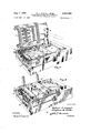
- FIGURE 1 is a front perspective view of a foam backrest for a chair of the recliner type commonly installed in busses, airplanes and other vehicles, the backrest being here shown without its upholstery cover material;
- FIGURE 2 is a rear perspective view of the same
- FIGURE 3 is a front perspective view of the internal frame of the backrest
- FIGURE 4 is a horizontal sectional view of the backrest taken on lines 44 of FIGURES 1 and 2, the plane of section through the internal frame of the backrest being indicated also by the line 44 of FIGURE 3;
- FIGURE 5 is a perspective view of a pre-foamed insert which forms part of the completed backrest
- FIGURE 6 is a fragmentary perspective view of a mold in which the foamed backrest is formed, the mold being here shown open and empty;
- FIGURE 7 is a perspective view illustrating the initial steps in performing the method by which the backrest is made
- FIGURE 8 is a perspective view illustrating further steps in performing the method of the invention.
- FIGURE 9 is a perspective view of the mold with the cover thereof in closed position
- FIGURE 10 is a perspective view illustrating the method step of removing the completed foam backrest from the mold.
- FIGURE 11 is a perspective view illustrating spraying of the interior of the mold prior to foaming a succeeding backrest therein.
- the completed foam backrest shown in FIGURES 1 and 2 has an internal foundation frame of metal or other rigid material, as seen in FIGURE 3.
- the frame comprises a lower back part in the form of an open rectangular framework, and an upper head part 21 which is pivotally connected at 22 to the upper end of the lower back part 20.
- the head part 21 is thus mounted on the back part 20 for articulated swinging movement between several positions of fore-and-aft adjustment relative to the back part 20.
- the mechanical connections between the head part 21 and the back part 20 include, in addition to the pivot means indicated at 22, springs 23 for normally urging the head part 21 in a rearwardly direction, and a latch mechanism indicated at 24 for securing the head part in a selected forwardly moved position and for releasing the head part when in its extreme forward position so that it is returned by springs 23 to its extreme rearward position.
- burlap 25 is adhesively applied to the lower back part 20 of the frame to effectively seal the opening in this part 20 against the passage of any appreciable amount of foaming material therethrough.
- Certain attachment openings designated 26 in FIGURE 2 are taped shut as seen at 27 in FIGURE 3 to prevent the passage of foaming material therethrough.
- the borehole in an attachment bushing 28 is taped shut to prevent the entry of foaming material.
- a pro-foamed headrest insert 29 is provided, this being a polyether urethane type foam of low density and consequently relatively great resilience.
- This headrest insert 29 is placed in the headrest region of the mold 30 as seen in FIGURE 7 and is held in position by spikes 31 in the mold 30 (see FIGURE 6).
- Frame locating pins 32 are projected into the mold 30 by means of suitable mechanism mounted on the outside of the mold and including an operating lever 33 which is thrown forwardly to its position seen in FIGURES 6-9 and 11 to project the pins 32 into the mold.
- FIGURE 7 The first part of the pouring procedure is illustrated in FIGURE 7.
- a measured amount of polyether urethane type foaming material in a fluid state is introduced into the mold through a nozzle 34 which is passed back and forth between one end and the other end of the mold as indicated by the dotted lines and arrows of FIGURE 7. This insures an even distribution of the foaming material in the mold 30.
- the metal frame is placed in position in the mold as seen in FIGURE 8.
- This frame serves as a barrier to the foaming of the material which had previously been injected into the mold. Minute amounts of the foaming material penetrate the interstices of the burlap 25 thus insuring a firm bond between the frame and 'the foam.
- a measured amount of the foaming material is next introduced into the mold behind the upper head part 21 of the frame as indicated ⁇ by the dotted lines and arrows in this view.
- the mold cover 37 is then closed and clamped tightly shut by means of clamps 38 so that all of the foaming material is confined within the mold.
- the cover 37 is so constructed that the region behind the lower back part 20 of the frame is completely sealed off and none of the foaming material can enter this region.
- the mold is passed through a baking oven so that the foamed material in the mold is completely cured.
- the completed foam backrest with its in-ternal'frame is then stripped from I the mold using .a large knife 39 as necessary. It is desirable that the completed backrest be'crushed, while? still warm, in a suitable press to break down the individual gas bubbles or cells in a uniform manner so as to prevent shrinkage of these cells, and consequent shrinkage of the entire cushion, upon cooling.
- the interior of the mold Prior to re-use of the mold to make another cushion, the interior of the mold is sprayed with a release agent such as a low-temperature melting wax, as seen ,in
- FIGURE 11 This release agent'facilitates removal of succeeding cushions from the mold.
- the foaming material which is, used in'the foaming 1 process hereinabove described is of a type which produces a relatively high density and relatively fir-m resilient foam, by contrast with the low density, more resilient headrestinsert, and the result is a backrest of unusual comfort.
- the headrest insert is slightly compressed, so that when the completed cushion is removed from the mold the outer surface "of the insert assumes an outwardly crownedor' contoured surface, as seen in FIGURE 4, which is de-- sirable.
- the invention provides an: improved cushion and method of making the same and. while but one construction and one method have been herein shownand described it will be understood that numerous constructional details and method steps may directions, flexing said cushion to bend it into a curved.
- ALEXANDER H BRODME-RKEL, Primary Examiner.
Landscapes
- Casting Or Compression Moulding Of Plastics Or The Like (AREA)
Description
g- 1966 R. c. ANGELL ETAL 8 METHOD FOR MAKING FOAM BACKRESTS FOR VEHICLE RECLINING CHAIRS Filed Sept. 18, 1963 4 Sheets-Sheet 1 I INVENTORS Rafiem @Aagell Jm zwu 3.160111 AIM/t7 S Q ATTORNEY WITNESS BY Aug. 2, 1966 R. c. ANGELL ETAL 3,264,382
METHOD FOR MAKING FOAM BACKRESTS FOR VEHICLE RECLXNING CHAIRS Filed Sept. 18, 1963 4 Sheets-Sheet 2 INVENTOR$ 05am- 6. Angell hem -KOIli.
WITNESS dead;
Ava/w; S Q/wurm I ATTORNEY Aug. 2, 1966 R. c. ANGELL ETAL 3,264,382
METHOD FOR MAKING FOAM BACKRESTS FOR VEHICLE RECLINING CHAIRS Filed Sept. 18, 1963 4 Sheets-Sheet 5 1NVENTOR$ Baker C -A-ZZJGIZ .S'iephen. .B. Kalli.
Ala/w; 3. Q/wwm 4/0. ATTORNEY Aug. 2, 1966 R. c. ANGELL ETAL 3,264,382
METHOD FOR MAKING FOAM BACKRESTS Filed Sept. 18, 1965 WITNESS FOR VEHICLE RECLINING CHAIRS 4 Sheets-Sheet 4 INVENTORS ATTORNEY United States Patent Office Patented August 2, 1966 The present invention relates to a method for making foam cushions and more particularly to foam backrests for vehicle reclining chairs.
The primary objects of the invention are to provide a method of foaming cushions having regions of different density and resilience, e.g. the backrest cushion of a recliner. wherein the main body of the cushion is comprised of a relatively firm foam material and wherein the headrest is comprised of foam material of greater resilience; to provide a novel method of foaming cushions in which each cushion has a portion of its outer surface contoured outwardly; and to provide a method of foaming a cushion having an internal frame comprising rigid parts mechanically connected for articulated movement relative to each other, e.g. a recliner backrest having an upper headrest portion swingable between positions of fore-and-aft adjustment; and to provide a method for making a backrest construction for a vehicle recliner or the like which is durable and comfortable in use, reasonably economical in manufacture and attractive in appearance.
The invention is illustrated by the accompanying drawings, wherein:
FIGURE 1 is a front perspective view of a foam backrest for a chair of the recliner type commonly installed in busses, airplanes and other vehicles, the backrest being here shown without its upholstery cover material;
FIGURE 2 is a rear perspective view of the same;
FIGURE 3 is a front perspective view of the internal frame of the backrest;
FIGURE 4 is a horizontal sectional view of the backrest taken on lines 44 of FIGURES 1 and 2, the plane of section through the internal frame of the backrest being indicated also by the line 44 of FIGURE 3;
FIGURE 5 is a perspective view of a pre-foamed insert which forms part of the completed backrest;
FIGURE 6 is a fragmentary perspective view of a mold in which the foamed backrest is formed, the mold being here shown open and empty;
FIGURE 7 is a perspective view illustrating the initial steps in performing the method by which the backrest is made;
FIGURE 8 is a perspective view illustrating further steps in performing the method of the invention;
FIGURE 9 is a perspective view of the mold with the cover thereof in closed position;
FIGURE 10 is a perspective view illustrating the method step of removing the completed foam backrest from the mold; and
FIGURE 11 is a perspective view illustrating spraying of the interior of the mold prior to foaming a succeeding backrest therein.
Referring now in detail to these drawings, the completed foam backrest shown in FIGURES 1 and 2 has an internal foundation frame of metal or other rigid material, as seen in FIGURE 3. The frame comprises a lower back part in the form of an open rectangular framework, and an upper head part 21 which is pivotally connected at 22 to the upper end of the lower back part 20. The head part 21 is thus mounted on the back part 20 for articulated swinging movement between several positions of fore-and-aft adjustment relative to the back part 20. The mechanical connections between the head part 21 and the back part 20 include, in addition to the pivot means indicated at 22, springs 23 for normally urging the head part 21 in a rearwardly direction, and a latch mechanism indicated at 24 for securing the head part in a selected forwardly moved position and for releasing the head part when in its extreme forward position so that it is returned by springs 23 to its extreme rearward position. Complete details of this latch mechanism indicated at 24 are disclosed in US. Patent No. 2,828,810, issued April 1, 1958 :to Chester J. B=arecki and Oscar J. Nelson and by them assigned to our assignee.
Pre-foaming operations Prior to foaming of the complete foamed backrest, certain pre-foaming operations are performed. Burlap 25 is adhesively applied to the lower back part 20 of the frame to effectively seal the opening in this part 20 against the passage of any appreciable amount of foaming material therethrough. Certain attachment openings designated 26 in FIGURE 2, the purpose of which is unimportant to an understanding of the present invention, are taped shut as seen at 27 in FIGURE 3 to prevent the passage of foaming material therethrough. Also, the borehole in an attachment bushing 28 is taped shut to prevent the entry of foaming material. Next, the mechanical connections 22, 23 and 24 between the upper head part 21 and the lower back part 20 of the frame, are heavily encased in grease.
A pro-foamed headrest insert 29 is provided, this being a polyether urethane type foam of low density and consequently relatively great resilience. This headrest insert 29 is placed in the headrest region of the mold 30 as seen in FIGURE 7 and is held in position by spikes 31 in the mold 30 (see FIGURE 6).
Frame locating pins 32 are projected into the mold 30 by means of suitable mechanism mounted on the outside of the mold and including an operating lever 33 which is thrown forwardly to its position seen in FIGURES 6-9 and 11 to project the pins 32 into the mold.
Pouring procedure The first part of the pouring procedure is illustrated in FIGURE 7. A measured amount of polyether urethane type foaming material in a fluid state is introduced into the mold through a nozzle 34 which is passed back and forth between one end and the other end of the mold as indicated by the dotted lines and arrows of FIGURE 7. This insures an even distribution of the foaming material in the mold 30.
Next the metal frame is placed in position in the mold as seen in FIGURE 8. This frame serves as a barrier to the foaming of the material which had previously been injected into the mold. Minute amounts of the foaming material penetrate the interstices of the burlap 25 thus insuring a firm bond between the frame and 'the foam. The locator pins 32, and slots 35 in the mold into which lit the lower end portions 36 of the lower frame part 20, space the frame slightly inwardly from the sides of the mold so as to provide foam material at the sides of the backrest.
As also seen in FIGURE 8, a measured amount of the foaming material is next introduced into the mold behind the upper head part 21 of the frame as indicated \by the dotted lines and arrows in this view. The mold cover 37 is then closed and clamped tightly shut by means of clamps 38 so that all of the foaming material is confined within the mold. The cover 37 is so constructed that the region behind the lower back part 20 of the frame is completely sealed off and none of the foaming material can enter this region. After the mold is clamped shut and the foaming is complete, the mold is passed through a baking oven so that the foamed material in the mold is completely cured.
mold, as seen in FIGURE 10. The completed foam backrest with its in-ternal'frame is then stripped from I the mold using .a large knife 39 as necessary. It is desirable that the completed backrest be'crushed, while? still warm, in a suitable press to break down the individual gas bubbles or cells in a uniform manner so as to prevent shrinkage of these cells, and consequent shrinkage of the entire cushion, upon cooling.
Prior to re-use of the mold to make another cushion, the interior of the mold is sprayed with a release agent such as a low-temperature melting wax, as seen ,in
FIGURE 11. This release agent'facilitates removal of succeeding cushions from the mold.
The foaming material which is, used in'the foaming 1 process hereinabove described is of a type which produces a relatively high density and relatively fir-m resilient foam, by contrast with the low density, more resilient headrestinsert, and the result is a backrest of unusual comfort. During the foaming operation described, the headrest insert is slightly compressed, so that when the completed cushion is removed from the mold the outer surface "of the insert assumes an outwardly crownedor' contoured surface, as seen in FIGURE 4, which is de-- sirable.
It will be seen that the upper head part 21 of the frame and itsmechauical connections to the lower back part 20 of the frame are completely enclosed .by foam, with several resultant advantages. The grease which heavily encases the mechanical connections cannot escape and these articulated parts are thus permanently lubri-i cated. It has been found that the presence of the grease in no way interferes with the foaming operation. It is to be noted also that the foam on the back side of the headrest provides a protective padding for an occupant of the next chair to the rear in the event he is suddenly thrown forwardly as in a crash.
It will thus be seen that the invention provides an: improved cushion and method of making the same and. while but one construction and one method have been herein shownand described it will be understood that numerous constructional details and method steps may directions, flexing said cushion to bend it into a curved.
body with said butt ends facing substantially in the same 4' direct-ion, securing said body While ,in'saidflexed and curved positionwithin a mold conforming generally=to the shape of the finished backrest, introducing a highdensity type foamable plastic materialinto the mold .to
fill the mold and to unitefwith the butt ends of said.
headrest cushion, and removing said united backrest and headrest [from said mold,
2. The method of claim 1 ;inwhich' the preformed headrest cushion is provided with a bevel at one end thereof.
3. The method of claim 1 in which'spacers are placed along side portions of said headrest cushion before introducing sa-idhigh-density type foamable plastic material into the mold whereby upon removal of said backrest from said mold side: portions of said headrestcushion are spaced from said backrest body. v
4. Ina method for forming 'a chair foam backrest having an outvvau'dly-contouredv headrest of greater resilience than the-body of the-backrest, the! steps of flexing a thick rectangular foam headrest cushion of low-density type .fo'arnable :plastic .materialto bend, the cushion into a curvedshape with the ends of the cushion facing'substantially in the same direction, securing said body while in said flexed and curved position within a mold conforming generally to the shape of the finishedbackrest, introducing a highrdensity type foarnahle plastic material into the mold to fill the mold and to unite with they ends of said headrest cushion, andtrernoving saidunited backrest and headrest from said mold.
References Cited by the Examiner UNITED STATES PATENTS 2,138,314 11/1938 Van Derveer h 297-460 2,801,678 8/1957 Brandon 29 7 39 2,828,810 4/1958 Barecki et al. 297396 2,838,100 6/1958 Follows 2644-45 XRC 2,839,125- 6/1958 Brandon 297-396 2 2,845,997 8/ 195 8 Waite ,26446'X R 2,908,943 10/1959 Miller 26 4 46 2,927,876 3/1960? Hoplpe et al 264-.-'46 XR 3,042,137 7/1962 Mathues et al. 26446 'XR- 3,082,486 3/1963 Khawam {$11 al. 264 -45 3,086,819 4/1963 Etfeny 2974 3,112,987 12/1963 Griffiths'et ali 26 4-45 3,161,436 12/1964 Hood 264-456 XR FOREIGN PATENTS 859,314 1/1961 Great Britain.
ALEXANDER H; BRODME-RKEL, Primary Examiner. FRANK B. SHERRY, Examiner.
C. A; NUNBERG, P. E. ANDERSON,1
Assistant Examinersi
Claims (1)
1. IN A METHOD FOR FORMING A CHAIR FOAM BACKREST HAVING AN OUTWARDLY-CONTOURED HEADREST OF GREATER RESILIENCE THAN THE BODY OF THE BACKREST, THE STEPS OF PREFORMING A RECTANGULAR RESILIENT THICK FOAM HEADREST CUSHION OF LOW-DENSITY TYPE FOAMABLE PLASTIC MATERIAL WITH THE BUTT ENDS OF THE CUSHION TO BEND IT INTO A CURVED DIRECTION, FLEXING SAID CUSHION TO BEND IT INTO A CURVED BODY WITH SAID BUTT ENDS FACING SUBSTANTIALLY IN THE SAME DIRECTION, SECURING SAID BODY WHILE IN SAID FLEXED AND CURVED POSITION WITHIN A MOLD CONFORMING GENERALLY TO THE SHAPE OF THE FINISHED BACKREST, INTRODUCING A HIGHDENSITY TYPE FOAMABLE PLASTIC MATERIAL INTO THE MOLD TO
Priority Applications (1)
| Application Number | Priority Date | Filing Date | Title |
|---|---|---|---|
| US309813A US3264382A (en) | 1963-09-18 | 1963-09-18 | Method for making foam backrests for vehicle reclining chairs |
Applications Claiming Priority (1)
| Application Number | Priority Date | Filing Date | Title |
|---|---|---|---|
| US309813A US3264382A (en) | 1963-09-18 | 1963-09-18 | Method for making foam backrests for vehicle reclining chairs |
Publications (1)
| Publication Number | Publication Date |
|---|---|
| US3264382A true US3264382A (en) | 1966-08-02 |
Family
ID=23199769
Family Applications (1)
| Application Number | Title | Priority Date | Filing Date |
|---|---|---|---|
| US309813A Expired - Lifetime US3264382A (en) | 1963-09-18 | 1963-09-18 | Method for making foam backrests for vehicle reclining chairs |
Country Status (1)
| Country | Link |
|---|---|
| US (1) | US3264382A (en) |
Cited By (42)
| Publication number | Priority date | Publication date | Assignee | Title |
|---|---|---|---|---|
| US3498669A (en) * | 1968-03-05 | 1970-03-03 | Budd Co | Seat back construction |
| US3531552A (en) * | 1967-05-04 | 1970-09-29 | Eaton Yale & Towne | Method of making composite load supporting structure |
| US3541642A (en) * | 1968-03-27 | 1970-11-24 | Reichhold Chemicals Inc | Casting machine |
| US3623931A (en) * | 1967-11-13 | 1971-11-30 | Hollis L Van Hosen | Method of making plastic cushion product |
| US3671981A (en) * | 1970-10-20 | 1972-06-27 | Sarah B Smith | Invalid or geriatric toilet seat |
| US3729228A (en) * | 1970-04-10 | 1973-04-24 | Toyota Motor Co Ltd | Vehicle seat provided with a head rest |
| US3758159A (en) * | 1970-03-11 | 1973-09-11 | Universal Oil Prod Co | Vehicle seat construction |
| US3929948A (en) * | 1971-11-03 | 1975-12-30 | Gen Tire & Rubber Co | Method for fabricating impact absorbing safety structure |
| US3954926A (en) * | 1971-06-03 | 1976-05-04 | Fritz Wilhelm Pahl | Method of molding a composite reinforced foamed product |
| US3978181A (en) * | 1970-10-12 | 1976-08-31 | Vahle Klaus Heinrich | Process for making a foam plastic resin encased roller |
| JPS52147503U (en) * | 1976-05-06 | 1977-11-09 | ||
| US4185342A (en) * | 1978-06-16 | 1980-01-29 | Young Raymond E | Portable, adjustable backrest for beds and the like |
| US4190697A (en) * | 1979-01-15 | 1980-02-26 | Milsco Manufacturing Company | Multidensity foam article and method of preparation |
| US4525130A (en) * | 1984-05-07 | 1985-06-25 | Netznik Frederick P | Adjustable molding frame |
| US4544126A (en) * | 1984-10-01 | 1985-10-01 | General Motors Corporation | Molding apparatus for simultaneously forming a cavity and encapsulating a frame in a foamed body |
| USD284032S (en) | 1983-12-20 | 1986-05-27 | Wahl Clipper Corporation | Back massager |
| DE3616621A1 (en) * | 1985-05-17 | 1986-11-20 | Villamosipari Kutató Intézet, Budapest | METHOD FOR PRODUCING ESPECIALLY DAMAGE TO THE VOEGEL RESISTANT HIGH VOLTAGE INSULATING MATERIAL, REMOTE METHOD AND DEVICE FOR PRODUCING THE INSULATING MATERIAL |
| US4637789A (en) * | 1985-05-13 | 1987-01-20 | Netznik Frederick P | Cushion fabrication apparatus |
| US4670925A (en) * | 1984-01-31 | 1987-06-09 | Clerprem S.R.L. | Process for the production of a cushion for a seat or the back for a motor vehicle or the like comprising two layers of foamed material with different properties and cushion prepared by the process |
| US4710414A (en) * | 1984-07-10 | 1987-12-01 | Minnesota Mining And Manufacturing Company | Fastener assembly with heat shrinkable film cover |
| US4792111A (en) * | 1985-10-31 | 1988-12-20 | Tachi-S Co. | Forming die for forming a vehicle seat foam cushion member with a pile-type fastener |
| US4814036A (en) * | 1985-07-17 | 1989-03-21 | Velcro Industries B.V. | Method for adapting separable fasteners for attachment to other objects |
| US4933224A (en) * | 1985-07-17 | 1990-06-12 | Velcro Industries, B.V. | Method for adapting separable fasteners for attachment to other objects |
| US4975229A (en) * | 1985-04-16 | 1990-12-04 | Honda Giken Kogyo Kabushiki Kaisha | Process for producing laminated resin foam |
| US4998354A (en) * | 1990-06-20 | 1991-03-12 | Pin Dot Products | Mechanical shape sensor |
| USD317840S (en) | 1989-12-04 | 1991-07-02 | Dan Jagdat | Pillow |
| EP0431981A3 (en) * | 1989-12-08 | 1991-09-11 | Bridgestone Corporation | Making polyurethane seat paddings |
| US5089191A (en) * | 1990-03-28 | 1992-02-18 | Woodbridge Foam Corporation | Process for manufacturing a padded element |
| WO1992003278A1 (en) * | 1987-12-04 | 1992-03-05 | Carter Engineering And Consulting | Sealing gasket for reticulated foam filter and process therefor |
| US5096639A (en) * | 1990-03-28 | 1992-03-17 | Woodbridge Foam Corporation | Process for manufacturing a padded element |
| US5193285A (en) * | 1991-08-01 | 1993-03-16 | Pin Dot Products | Mechanical shape sensor and data recorder |
| US5400490A (en) * | 1993-02-26 | 1995-03-28 | Woodbridge Foam Corporation | Method of molding a seat having anchoring means connected thereto |
| US5518293A (en) * | 1994-04-25 | 1996-05-21 | Coy; Duane E. | Child car seat with two laterally disposed seats |
| US5522106A (en) * | 1993-11-15 | 1996-06-04 | Special Health Systems Ltd. | Seat cushion assembly |
| EP1380233A4 (en) * | 2001-04-16 | 2009-03-04 | Ts Tech Co Ltd | Sheet for vehicle and method for manufacture thereof |
| US20090124935A1 (en) * | 2007-11-12 | 2009-05-14 | Staszak Jeffrey R | Bicycle Seat Sizer And Positioning Device |
| US20110156467A1 (en) * | 2009-12-24 | 2011-06-30 | Toyota Boshoku Kabushiki Kaisha | Vehicle seat cushion and manufacturing method thereof |
| US20110272976A1 (en) * | 2007-10-31 | 2011-11-10 | Wen Wei | Tattoo chair |
| US20120068519A1 (en) * | 2009-03-09 | 2012-03-22 | Johnson Control Technology Company | Vehicle seat cushion |
| US20130134760A1 (en) * | 2011-11-28 | 2013-05-30 | Ford Global Technologies, Llc | Dual firmness head restraint |
| US20160158979A1 (en) * | 2013-07-31 | 2016-06-09 | Bridgestone Corporation | Molded foam member manufacturing method, and shock absorbing member |
| USD885792S1 (en) * | 2017-05-27 | 2020-06-02 | Chengdu YiShouWeiSheng Technology Co., Ltd | Back and head cushion |
Citations (14)
| Publication number | Priority date | Publication date | Assignee | Title |
|---|---|---|---|---|
| US2138314A (en) * | 1937-12-29 | 1938-11-29 | Karpen & Bros S | Seat back |
| US2801678A (en) * | 1953-07-02 | 1957-08-06 | Coach & Car Equipment Corp | Adjustable head rest for seat structure |
| US2828810A (en) * | 1956-04-09 | 1958-04-01 | American Seating Co | Adjustable headrest |
| US2838100A (en) * | 1955-12-12 | 1958-06-10 | John W Follows | Chair, sofa, or similar article |
| US2839125A (en) * | 1954-05-19 | 1958-06-17 | Coach & Car Equip Corp | Adjustable head roll for seat structure |
| US2845997A (en) * | 1954-03-09 | 1958-08-05 | Curtiss Wright Corp | Foamed plastic seat and the like |
| US2908943A (en) * | 1957-10-25 | 1959-10-20 | Bill Jack Scient Instr Co | Process for molding two-layer polyurethane articles |
| US2927876A (en) * | 1954-07-30 | 1960-03-08 | Bayer Ag | Article comprising a cellular core and sheath |
| GB859314A (en) * | 1956-11-09 | 1961-01-18 | Jean Bourgois | Improvements in and relating to expanded plastic materials produced by moulding, andto the manufacture of articles from them |
| US3042137A (en) * | 1959-09-09 | 1962-07-03 | Gen Motors Corp | Vehicle instrument and dashboard assemblies |
| US3082486A (en) * | 1959-03-25 | 1963-03-26 | Khawam Antoine | Method of molding a reinforced foam article |
| US3086819A (en) * | 1960-05-03 | 1963-04-23 | Ford Motor Co | Vehicle seat structure |
| US3112987A (en) * | 1959-03-26 | 1963-12-03 | Austin Motor Co Ltd | Production of cushioned seats |
| US3161436A (en) * | 1962-03-27 | 1964-12-15 | Davidson Rubber Company Inc | Pre-stressed molded foam cushioning element |
-
1963
- 1963-09-18 US US309813A patent/US3264382A/en not_active Expired - Lifetime
Patent Citations (14)
| Publication number | Priority date | Publication date | Assignee | Title |
|---|---|---|---|---|
| US2138314A (en) * | 1937-12-29 | 1938-11-29 | Karpen & Bros S | Seat back |
| US2801678A (en) * | 1953-07-02 | 1957-08-06 | Coach & Car Equipment Corp | Adjustable head rest for seat structure |
| US2845997A (en) * | 1954-03-09 | 1958-08-05 | Curtiss Wright Corp | Foamed plastic seat and the like |
| US2839125A (en) * | 1954-05-19 | 1958-06-17 | Coach & Car Equip Corp | Adjustable head roll for seat structure |
| US2927876A (en) * | 1954-07-30 | 1960-03-08 | Bayer Ag | Article comprising a cellular core and sheath |
| US2838100A (en) * | 1955-12-12 | 1958-06-10 | John W Follows | Chair, sofa, or similar article |
| US2828810A (en) * | 1956-04-09 | 1958-04-01 | American Seating Co | Adjustable headrest |
| GB859314A (en) * | 1956-11-09 | 1961-01-18 | Jean Bourgois | Improvements in and relating to expanded plastic materials produced by moulding, andto the manufacture of articles from them |
| US2908943A (en) * | 1957-10-25 | 1959-10-20 | Bill Jack Scient Instr Co | Process for molding two-layer polyurethane articles |
| US3082486A (en) * | 1959-03-25 | 1963-03-26 | Khawam Antoine | Method of molding a reinforced foam article |
| US3112987A (en) * | 1959-03-26 | 1963-12-03 | Austin Motor Co Ltd | Production of cushioned seats |
| US3042137A (en) * | 1959-09-09 | 1962-07-03 | Gen Motors Corp | Vehicle instrument and dashboard assemblies |
| US3086819A (en) * | 1960-05-03 | 1963-04-23 | Ford Motor Co | Vehicle seat structure |
| US3161436A (en) * | 1962-03-27 | 1964-12-15 | Davidson Rubber Company Inc | Pre-stressed molded foam cushioning element |
Cited By (49)
| Publication number | Priority date | Publication date | Assignee | Title |
|---|---|---|---|---|
| US3531552A (en) * | 1967-05-04 | 1970-09-29 | Eaton Yale & Towne | Method of making composite load supporting structure |
| US3623931A (en) * | 1967-11-13 | 1971-11-30 | Hollis L Van Hosen | Method of making plastic cushion product |
| US3498669A (en) * | 1968-03-05 | 1970-03-03 | Budd Co | Seat back construction |
| US3541642A (en) * | 1968-03-27 | 1970-11-24 | Reichhold Chemicals Inc | Casting machine |
| US3758159A (en) * | 1970-03-11 | 1973-09-11 | Universal Oil Prod Co | Vehicle seat construction |
| US3729228A (en) * | 1970-04-10 | 1973-04-24 | Toyota Motor Co Ltd | Vehicle seat provided with a head rest |
| US3978181A (en) * | 1970-10-12 | 1976-08-31 | Vahle Klaus Heinrich | Process for making a foam plastic resin encased roller |
| US3671981A (en) * | 1970-10-20 | 1972-06-27 | Sarah B Smith | Invalid or geriatric toilet seat |
| US3954926A (en) * | 1971-06-03 | 1976-05-04 | Fritz Wilhelm Pahl | Method of molding a composite reinforced foamed product |
| US3929948A (en) * | 1971-11-03 | 1975-12-30 | Gen Tire & Rubber Co | Method for fabricating impact absorbing safety structure |
| JPS52147503U (en) * | 1976-05-06 | 1977-11-09 | ||
| US4185342A (en) * | 1978-06-16 | 1980-01-29 | Young Raymond E | Portable, adjustable backrest for beds and the like |
| US4190697A (en) * | 1979-01-15 | 1980-02-26 | Milsco Manufacturing Company | Multidensity foam article and method of preparation |
| USD284032S (en) | 1983-12-20 | 1986-05-27 | Wahl Clipper Corporation | Back massager |
| US4670925A (en) * | 1984-01-31 | 1987-06-09 | Clerprem S.R.L. | Process for the production of a cushion for a seat or the back for a motor vehicle or the like comprising two layers of foamed material with different properties and cushion prepared by the process |
| US4525130A (en) * | 1984-05-07 | 1985-06-25 | Netznik Frederick P | Adjustable molding frame |
| US4710414A (en) * | 1984-07-10 | 1987-12-01 | Minnesota Mining And Manufacturing Company | Fastener assembly with heat shrinkable film cover |
| US4544126A (en) * | 1984-10-01 | 1985-10-01 | General Motors Corporation | Molding apparatus for simultaneously forming a cavity and encapsulating a frame in a foamed body |
| US4975229A (en) * | 1985-04-16 | 1990-12-04 | Honda Giken Kogyo Kabushiki Kaisha | Process for producing laminated resin foam |
| US4637789A (en) * | 1985-05-13 | 1987-01-20 | Netznik Frederick P | Cushion fabrication apparatus |
| DE3616621A1 (en) * | 1985-05-17 | 1986-11-20 | Villamosipari Kutató Intézet, Budapest | METHOD FOR PRODUCING ESPECIALLY DAMAGE TO THE VOEGEL RESISTANT HIGH VOLTAGE INSULATING MATERIAL, REMOTE METHOD AND DEVICE FOR PRODUCING THE INSULATING MATERIAL |
| US4814036A (en) * | 1985-07-17 | 1989-03-21 | Velcro Industries B.V. | Method for adapting separable fasteners for attachment to other objects |
| US4933224A (en) * | 1985-07-17 | 1990-06-12 | Velcro Industries, B.V. | Method for adapting separable fasteners for attachment to other objects |
| US4792111A (en) * | 1985-10-31 | 1988-12-20 | Tachi-S Co. | Forming die for forming a vehicle seat foam cushion member with a pile-type fastener |
| WO1992003278A1 (en) * | 1987-12-04 | 1992-03-05 | Carter Engineering And Consulting | Sealing gasket for reticulated foam filter and process therefor |
| USD317840S (en) | 1989-12-04 | 1991-07-02 | Dan Jagdat | Pillow |
| EP0431981A3 (en) * | 1989-12-08 | 1991-09-11 | Bridgestone Corporation | Making polyurethane seat paddings |
| US5096639A (en) * | 1990-03-28 | 1992-03-17 | Woodbridge Foam Corporation | Process for manufacturing a padded element |
| US5089191A (en) * | 1990-03-28 | 1992-02-18 | Woodbridge Foam Corporation | Process for manufacturing a padded element |
| US4998354A (en) * | 1990-06-20 | 1991-03-12 | Pin Dot Products | Mechanical shape sensor |
| US5193285A (en) * | 1991-08-01 | 1993-03-16 | Pin Dot Products | Mechanical shape sensor and data recorder |
| US5400490A (en) * | 1993-02-26 | 1995-03-28 | Woodbridge Foam Corporation | Method of molding a seat having anchoring means connected thereto |
| US5542747A (en) * | 1993-02-26 | 1996-08-06 | Woodbridge Foam Corporation | Seat having a frame element of high-density, rigid foam |
| US5522106A (en) * | 1993-11-15 | 1996-06-04 | Special Health Systems Ltd. | Seat cushion assembly |
| US5518293A (en) * | 1994-04-25 | 1996-05-21 | Coy; Duane E. | Child car seat with two laterally disposed seats |
| EP1380233A4 (en) * | 2001-04-16 | 2009-03-04 | Ts Tech Co Ltd | Sheet for vehicle and method for manufacture thereof |
| US20110272976A1 (en) * | 2007-10-31 | 2011-11-10 | Wen Wei | Tattoo chair |
| US8864233B2 (en) * | 2007-10-31 | 2014-10-21 | Wen Wei | Tattoo chair |
| US20090124935A1 (en) * | 2007-11-12 | 2009-05-14 | Staszak Jeffrey R | Bicycle Seat Sizer And Positioning Device |
| US9314187B2 (en) | 2007-11-12 | 2016-04-19 | Trek Bicycle Corporation | Bicycle seat sizer and positioning device |
| US20120068519A1 (en) * | 2009-03-09 | 2012-03-22 | Johnson Control Technology Company | Vehicle seat cushion |
| US20110156467A1 (en) * | 2009-12-24 | 2011-06-30 | Toyota Boshoku Kabushiki Kaisha | Vehicle seat cushion and manufacturing method thereof |
| US20130134760A1 (en) * | 2011-11-28 | 2013-05-30 | Ford Global Technologies, Llc | Dual firmness head restraint |
| US10011058B2 (en) * | 2011-11-28 | 2018-07-03 | Ford Global Technologies, Llc | Dual firmness head restraint |
| US20180290347A1 (en) * | 2011-11-28 | 2018-10-11 | Ford Global Technologies, Llc | Dual firmness head restraint |
| US11904512B2 (en) * | 2011-11-28 | 2024-02-20 | Ford Global Technologies, Llc | Dual firmness head restraint |
| US20160158979A1 (en) * | 2013-07-31 | 2016-06-09 | Bridgestone Corporation | Molded foam member manufacturing method, and shock absorbing member |
| US9815232B2 (en) * | 2013-07-31 | 2017-11-14 | Toyota Boshoku Kabushiki Kaisha | Molded foam member manufacturing method, and shock absorbing member |
| USD885792S1 (en) * | 2017-05-27 | 2020-06-02 | Chengdu YiShouWeiSheng Technology Co., Ltd | Back and head cushion |
Similar Documents
| Publication | Publication Date | Title |
|---|---|---|
| US3264382A (en) | Method for making foam backrests for vehicle reclining chairs | |
| US3208085A (en) | Resilient cushion | |
| US4403356A (en) | Seat cushions | |
| CA2273692C (en) | Method of manufacturing an interior automotive component and components made therefrom | |
| US5499413A (en) | Composite foam chair cushion and method | |
| US3112987A (en) | Production of cushioned seats | |
| US3840269A (en) | Lattice reinforced foam rubber seat bun and method of molding same | |
| JPH0249890B2 (en) | ||
| CN100496940C (en) | Method for making a monolithic elastic support and support obtained with said method | |
| US6419863B1 (en) | Method of moulding fillings and seats comprising such fillings | |
| DE102009041920A1 (en) | Vehicle seat assembly with polymer upholstery shell | |
| CN108724580A (en) | Method for manufacturing cushion material and foaming mould | |
| EP0899153A1 (en) | Vehicle seat | |
| WO2015045874A1 (en) | Breathable seat | |
| US3697133A (en) | Seat back structure | |
| CN103313880B (en) | Foam component and method of making foam component | |
| GB2197659A (en) | Process for preparing polyurethane foams having zones of differing hardness | |
| US11904523B2 (en) | Trim article having an integrated structural composition with variated densities and methods for making the same | |
| JP3501219B2 (en) | Manufacturing method of cushioning material | |
| JPH0976797A (en) | Seat cushion for automobile | |
| JP2020175253A (en) | Method of manufacturing vehicle seat pad | |
| JPH0349555Y2 (en) | ||
| JP2013129324A (en) | Seat cushion for vehicle | |
| JP2955309B2 (en) | Manufacturing method of vehicle cushion body | |
| JPH11137364A (en) | Vehicle seat and manufacturing method thereof |