WO2015015588A1 - 紙葉類処理装置 - Google Patents
紙葉類処理装置 Download PDFInfo
- Publication number
- WO2015015588A1 WO2015015588A1 PCT/JP2013/070694 JP2013070694W WO2015015588A1 WO 2015015588 A1 WO2015015588 A1 WO 2015015588A1 JP 2013070694 W JP2013070694 W JP 2013070694W WO 2015015588 A1 WO2015015588 A1 WO 2015015588A1
- Authority
- WO
- WIPO (PCT)
- Prior art keywords
- paper sheet
- transport
- speed
- unit
- banknote
- Prior art date
- Legal status (The legal status is an assumption and is not a legal conclusion. Google has not performed a legal analysis and makes no representation as to the accuracy of the status listed.)
- Ceased
Links
Images



Classifications
-
- B—PERFORMING OPERATIONS; TRANSPORTING
- B65—CONVEYING; PACKING; STORING; HANDLING THIN OR FILAMENTARY MATERIAL
- B65H—HANDLING THIN OR FILAMENTARY MATERIAL, e.g. SHEETS, WEBS, CABLES
- B65H7/00—Controlling article feeding, separating, pile-advancing, or associated apparatus, to take account of incorrect feeding, absence of articles, or presence of faulty articles
- B65H7/02—Controlling article feeding, separating, pile-advancing, or associated apparatus, to take account of incorrect feeding, absence of articles, or presence of faulty articles by feelers or detectors
-
- G—PHYSICS
- G07—CHECKING-DEVICES
- G07D—HANDLING OF COINS OR VALUABLE PAPERS, e.g. TESTING, SORTING BY DENOMINATIONS, COUNTING, DISPENSING, CHANGING OR DEPOSITING
- G07D11/00—Devices accepting coins; Devices accepting, dispensing, sorting or counting valuable papers
- G07D11/50—Sorting or counting valuable papers
-
- B—PERFORMING OPERATIONS; TRANSPORTING
- B65—CONVEYING; PACKING; STORING; HANDLING THIN OR FILAMENTARY MATERIAL
- B65H—HANDLING THIN OR FILAMENTARY MATERIAL, e.g. SHEETS, WEBS, CABLES
- B65H2511/00—Dimensions; Position; Numbers; Identification; Occurrences
- B65H2511/10—Size; Dimensions
- B65H2511/11—Length
-
- B—PERFORMING OPERATIONS; TRANSPORTING
- B65—CONVEYING; PACKING; STORING; HANDLING THIN OR FILAMENTARY MATERIAL
- B65H—HANDLING THIN OR FILAMENTARY MATERIAL, e.g. SHEETS, WEBS, CABLES
- B65H2511/00—Dimensions; Position; Numbers; Identification; Occurrences
- B65H2511/20—Location in space
- B65H2511/22—Distance
-
- B—PERFORMING OPERATIONS; TRANSPORTING
- B65—CONVEYING; PACKING; STORING; HANDLING THIN OR FILAMENTARY MATERIAL
- B65H—HANDLING THIN OR FILAMENTARY MATERIAL, e.g. SHEETS, WEBS, CABLES
- B65H2511/00—Dimensions; Position; Numbers; Identification; Occurrences
- B65H2511/40—Identification
- B65H2511/413—Identification of image
-
- B—PERFORMING OPERATIONS; TRANSPORTING
- B65—CONVEYING; PACKING; STORING; HANDLING THIN OR FILAMENTARY MATERIAL
- B65H—HANDLING THIN OR FILAMENTARY MATERIAL, e.g. SHEETS, WEBS, CABLES
- B65H2513/00—Dynamic entities; Timing aspects
- B65H2513/10—Speed
-
- B—PERFORMING OPERATIONS; TRANSPORTING
- B65—CONVEYING; PACKING; STORING; HANDLING THIN OR FILAMENTARY MATERIAL
- B65H—HANDLING THIN OR FILAMENTARY MATERIAL, e.g. SHEETS, WEBS, CABLES
- B65H2513/00—Dynamic entities; Timing aspects
- B65H2513/50—Timing
Definitions
- the present invention relates to a paper sheet processing apparatus.
- Examples of the paper sheet processing apparatus used for the cash scrutiny processing of a financial institution include a paper sheet sorting apparatus installed in the back yard of a bank head office or branch, or a cash center.
- Paper sheet sorting device is a paper sheet scrutiny process, counting the number of paper sheets, denomination, dirt, true / false judgment, correctness / separation process for sorting correct and non-performing bills, It is an apparatus that executes a banding process or the like.
- a regular ticket is a paper sheet that may be recirculated to the market after a scrutiny
- a non-performing ticket is a paper sheet that is not recirculated to the market due to dirt, tears, graffiti, etc. That's it.
- the processing speed when sorting paper sheets depends on the calculation load of the identification unit, the feeding speed and the transport speed of the paper sheets. For example, since the calculation load of the identification unit is different between the case of sorting by denomination and the case of sorting by damage, the sorting speed of paper sheets is different.
- Patent Document 1 describes a sensor output for detecting the type of paper sheet and a change in a feeding speed based on the size of the paper sheet.
- Patent Document 2 describes a paper sheet feeding direction. The change of the feeding speed based on the length of the paper and the interval between the paper sheets is described.
- the paper sheet feeding speed that is, the paper sheet length
- paper sheet length the paper sheet feeding speed
- Paper sheet transport interval the paper sheet transport interval
- Patent Documents 1 and 2 only the feeding speed is controlled according to the type and interval of the paper sheets, and the control of the feeding speed of the fed paper sheets and the arithmetic processing capability in the identification unit are taken into consideration. The optimization of the number of paper sheets that can be sorted in a long time was not considered.
- the number of paper sheets that can be sorted is optimized by considering not only the paper sheet feeding speed but also the control of the feeding speed of the fed paper sheets and the calculation processing capability in the identification unit.
- An object of the present invention is to provide a processed paper sheet processing apparatus.
- the present invention provides a depositing unit that includes a feeding unit that feeds stored paper sheets one by one, a conveyance path that conveys the paper sheets fed by the feeding unit, An identification unit that acquires the length and image of the conveyed paper sheet, a control unit that examines the paper sheet on which the image has been acquired by the identification unit, and a paper sheet that has been examined by the control unit A paper sheet storage unit, and the control unit calculates a transport pitch necessary for sorting from the length of the paper sheet, and controls the transport speed of the transport path according to the transport pitch, Calculating a calculation time of calculation processing for discriminating the type of the paper sheet from the image acquired by the identification unit, and controlling the paper sheet feeding speed and the conveying speed by the feeding means according to the calculation time; It is characterized by.
- FIG. 1 is a schematic configuration diagram of a paper sheet sorting apparatus.
- the paper sheets in the present embodiment include, for example, banknotes, gift certificates, checks, various voting tickets, admission tickets, boarding tickets, expressways, telephones, use tickets for various facilities, securities, bonds, stock certificates, book tickets, etc.
- banknotes will be described.
- the paper sheet sorting apparatus 200 is a device that performs banknote scrutiny processing such as counting the number of loaded banknotes, denomination, dirt, authenticity determination, and damage separation processing.
- a mechanism such as a hopper 220, a sorting gate 230, a reject stacker 240, and stackers 245A to 245C is provided.
- the paper sheet sorting apparatus 200 includes a scanner 261, a number detection sensor 262, a pickup roller 271, a feed roller 272, a gate roller 273, a transport roller 274, and a bill transport path 275.
- the identification unit 210 is a mechanism that acquires an image of one length of a bill to be transported (the length in the bill transport direction, the bill length) via the scanner 261. Since the scanner 261 can acquire the entire front and back image of the banknote, it can also detect the banknote length, the length in a direction substantially perpendicular to the banknote length, and the skew (tilt) of the banknote being conveyed. The acquired front and back whole image of the banknote is used for the denomination, authenticity determination, and damage determination of the banknote. In addition, since the said banknote length is defined by the conveyance direction of a banknote, when a banknote is conveyed in a transversal direction, let a transversal direction be a banknote length. Similarly, when a banknote is conveyed in a longitudinal direction, let a longitudinal direction be banknote length.
- the hopper 220 is a depositing unit for banknotes, and is a mechanism for feeding out stored banknotes one by one. Specifically, among the banknotes stored in the hopper 220, the lowermost banknote is fed out by the pickup roller 271 and then fed out to the banknote transport path 275 by the feed roller 272 and the gate roller 273. At this time, when the feed roller 272 rotates once, one banknote is sent out to the banknote conveyance path 275. Accordingly, the higher the rotation speed of the feed roller 272 is, the more frequently the bill is fed out, and the rotation speed of the feed roller 272 and the bill feeding frequency are in a proportional relationship.
- the pickup roller 271, the feed roller 272, and the gate roller 273 are collectively referred to as “feeding unit”.
- the pickup roller 271, the feed roller 272, the gate roller 273, and the transport roller 274 are controlled by separate drive sources (not shown).
- the sorting gate (sorting unit) 230 is a mechanism that is provided on the banknote conveyance path 275 and sorts the banknotes scrutinized by the main control unit 250 according to the scrutiny results.
- the sorting gate 230 is provided in a length direction substantially perpendicular to the banknote length of the banknote in the banknote transport path 275.
- the stackers 240, 245A to 245C are banknote storage units for storing banknotes examined by the main control unit 250, and an opening for taking out banknotes is provided at the front of the apparatus (surface on which the hopper 220 is provided: left side in FIG. 1). Provided.
- banknotes are stored in the stackers 245A to 245C according to preset denominations or correctness, and banknotes that are not stored in the other stackers 245A to 245C, or a banknote transport state Banknotes or the like that could not be correctly identified by the main control unit 250 due to reasons such as being bad.
- the main control unit 250 is a control unit that controls the entire apparatus, and performs a scrutiny process on the banknotes for which images have been acquired by the identification unit 210. A specific configuration will be described together with a control block diagram of the paper sheet sorting apparatus shown in FIG.
- the number detection sensor 262 is a sensor that detects the number of bills fed out from the hopper 220 and conveyed to the bill conveyance path 275, and is provided closer to the hopper 220 than the identification unit 210, and the identification unit 210 and the hopper 220 It is provided in the position which detects the banknote which passes the banknote conveyance path 275 between.
- the conveyance roller 274 is a roller which conveys the banknote which passes the banknote conveyance path 275, and is comprised by the elastic member etc.
- FIG. 2 is a control block diagram of the paper sheet sorting apparatus 200.
- the sheet sorting apparatus 200 includes a main control unit 250, a ROM (Read Only Memory) 251 in which an operation program of the main control unit 250 is recorded, and a RAM in which the main control unit 250 records control data for controlling each unit in a readable / writable manner.
- (Random Access Memory) 252 a display operation unit 253 that accepts an input operation by an operator and displays data after the operation
- a communication unit 254 that transmits and receives information to and from a host device such as a host computer, and various types of information Storage unit 255 such as a RAM or HDD (Hard Disk Disk Drive).
- the main control unit 250 controls the temperature sensor 231 in addition to the sorting gate 230, the scanner 261, and the number detection sensor 262 described above.
- the temperature sensor 231 is a sensor that is installed in the vicinity of the sorting gate 230 and acquires the temperature of a driving unit such as an actuator that operates the sorting gate 230.
- the storage unit 255 has a larger storage area than the ROM 251 and the RAM 252 and stores reference information used for determining the authenticity of bills and information used as a reference for determining correct bills.
- the banknote feeding unit 256 is a control unit for the pickup roller 271, the feed roller 272, and the gate roller 273, and controls the banknotes stored in the hopper 220 to be fed out to the banknote transport path 275 one by one.
- the banknote transport unit 257 is a control unit for the banknote transport path 275, and when the banknotes fed from the hopper 220 are transported to the reject stacker 240 or the stackers 245A to 245C, a banknote transport belt, a transport roller 274, and a passage sensor. Control etc.
- the main control unit 250, the ROM 251, the RAM 252, the communication unit 254, the banknote feeding unit 256, and the banknote transport unit 257 may be collectively referred to as a “control unit”.
- the banknotes stored in the hopper 220 are fed one by one to the banknote transport path 275 by the pickup roller 271, the feed roller 272, and the gate roller 273, and are transported by the plurality of transport rollers 274.
- the number of bills conveyed is detected by the number detection sensor 262, and an image of the bill is acquired by the scanner 261 when passing through the identification unit 210.
- the main control unit 250 uses the acquired image to perform calculations and processing such as bill length measurement, counting, authenticity determination, and damage separation processing.
- the banknotes examined by the main control unit 250 are sorted by the sorting gate 230 into any of the various stackers 240, 245A to 245C.
- the banknote feeding frequency is set so that the interval (pitch) for feeding banknotes is shortened and the performance of identification unit 210 is maximized. Is to optimize.
- the same process is executed not only for this but also for Japanese yen banknotes, Chinese yuan banknotes, US dollar banknotes, Korean won banknotes, etc. To do.
- euro banknotes There are seven types of euro banknotes: 5 euro banknotes, 10 euro banknotes, 20 euro banknotes, 50 euro banknotes, 100 euro banknotes, 200 euro banknotes, and 500 euro banknotes. The higher the face value, the longer the banknote length. There is a feature. In this example, a process of distributing a banknote bundle in which 5 euro banknotes, 10 euro banknotes, and 20 euro banknotes are mixed into denominations will be described.
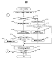
- FIG. 3 is a flowchart showing a process for controlling the conveyance speed of banknotes.
- the banknote feeding unit 256 feeds the banknote in the lowermost layer of the banknote bundle loaded in the hopper 220 by the pickup roller 271 and then feeds it to the banknote transport path 275 by the feed roller 272 and the gate roller 273 (S101). Subsequently, the main control unit 250 determines whether it is the first banknote by the number detection sensor 262 (S102). When it is the 1st banknote (S102: YES), the banknote length of a conveyance banknote is detected by the scanner 261 in the identification part 210 (S103).
- the banknote with the longest banknote length is the 500 euro banknote with the highest face value. Therefore, when delivering and transporting the first banknote, default values for the feed speed of the feed roller 272 and the transport speed of the banknote transport path 275 are set so that 500 euro banknotes can be sorted. Yes.
- the main control unit 250 determines the banknote length.
- a transport pitch necessary for sorting is calculated (S105), and the banknote transport unit 257 reduces the transport speed of the banknote transport path 275 (S106).
- the control of the bill feeding unit 256 is not changed. That is, since the conveyance speed of the banknote conveyance path 275 is lowered without reducing the feeding speed of the banknotes by the feed roller 272, the pitch of the banknotes to be conveyed can be shortened. Therefore, there is an advantage such as low noise and low power consumption because a minimum transport pitch that does not cause a sorting error is applied according to the banknote length of the banknote and the feeding speed is not changed.
- the banknote transport unit 257 increases the transport speed of the banknote transport path 275 (S110).
- the banknote transport unit 257 sorts the banknotes into the corresponding stackers 240, 245A to C (S111). This process is repeated until all the banknotes in the hopper 220 are exhausted (S112).
- the scanner 261 of the identification unit 210 acquires the length in the substantially vertical direction with respect to the banknote length and the inclination of the banknote with respect to the banknote length. Therefore, the main control unit 250 considers the influence on the conveyance pitch when the banknote is skewed by the length of the banknote (the banknote length, the length in the direction substantially perpendicular to the banknote length) and the inclination of the banknote, It is also possible to accurately calculate the transport pitch that can be distributed without problems in terms of control.
- FIG. 4 is a schematic view of a banknote transport state.
- L 1 is a banknote length
- L 2 is a length in a substantially vertical direction with respect to the banknote length
- ⁇ is an inclination of the banknote with respect to the banknote length.
- the denomination of the banknote is acquired by the scanner 261, and the correspondence between the denomination and the banknote length recorded in advance in the RAM 252 by the main control unit 250.
- the conveyance pitch may be calculated based on the relationship.
- the banknotes are smeared or torn, (a) banknotes with dirt (stains) on the banknote surface, (b) banknotes with graffiti on the banknote surface, (c) banknotes There are banknotes that are partially broken, (d) banknotes that are broken in part, and (e) banknotes that have holes in some of the banknotes.
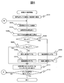
- the calculation load for denomination discrimination increases as the bill feeding frequency increases (that is, as the bill feeding speed increases), the load on the identification unit 210 increases. Therefore, it is necessary to control the bill feeding frequency so that an excessive load is not applied to the identification unit 210.
- the denomination determination process for the first conveyed banknote since the denomination to be conveyed is unknown, the denomination is operated at a payout frequency assuming the maximum calculation load.
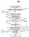
- the banknote feeding unit 256 feeds the banknote in the lowermost layer among the banknote bundles loaded in the hopper 220 by the pickup roller 271, and then feeds it to the banknote transport path 275 by the feed roller 272 and the gate roller 273 (S101). Subsequently, a banknote image is acquired by the scanner 261 in the identification unit 210 (S202). The main control unit 250 executes denomination calculation processing for determining the denomination from the acquired banknote image (S203).
- an average calculation time t is calculated for the most recently conveyed X (X: arbitrary) banknotes (S204).
- X arbitrary
- the average calculation time is calculated for the bills that are actually conveyed.
- the reason for calculating the average calculation time t is to suppress variations in calculation time for each sheet.
- the value of the feeding frequency is changed according to the calculated average calculation time t (see S207 and S209).
- the banknote feeding unit 256 decreases the feeding speed of the feed roller 272 (S209), and the banknote transport unit 257 decreases the transport speed of the banknote transport path 275 (S210). Thereby, the calculation load of the identification unit 210 and the main control unit 250 is reduced.
- the banknote transport unit 257 sorts the banknotes into the corresponding stackers 240, 245A to C (S111). This process is repeated until all the banknotes in the hopper 220 are exhausted (S112).
- the transport pitch is increased by increasing the transport speed when the banknote length of the banknote is maximum (S109, S110).
- the conveyance pitch is increased, but also the conveyance pitch suitable for the banknote length of the banknote to be conveyed can be applied by changing the conveyance pitch as needed with respect to the banknote length to be conveyed. Become more accurate.
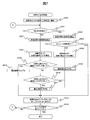
- the banknote feeding unit 256 feeds the banknote in the lowermost layer of the banknote bundle loaded in the hopper 220 by the pickup roller 271, and then feeds it to the banknote transport path 275 by the feed roller 272 and the gate roller 273 (S301). Subsequently, the main control unit 250 determines whether it is the first banknote by the number detection sensor 262 (S102). When it is the 1st banknote (S302: YES), the banknote length of a conveyance banknote is detected by the scanner 261 in the identification part 210 (S303).
- the main controller 250 determines the banknote length. Based on the above, a transport pitch necessary for sorting is calculated (S305), and the banknote transport unit 257 reduces the transport speed of the banknote transport path 275 (S306).
- the banknote length of the transported banknotes is detected by the scanner 261 in the identification unit 210 (S307), and the transport pitch necessary for sorting is determined from the result. Is calculated (S308). That is, in S301 to S308, processing similar to the processing in S101 to S108 in the first embodiment is executed.
- the main control unit 250 determines the transport pitch of the transported paper sheet calculated from the length of the paper sheet and the length of the paper sheet transported one sheet before.
- the conveyance pitch calculated from the comparison is compared, and the conveyance speed is controlled according to the comparison result. Specifically, the following processing is executed.
- the banknote transport unit 257 increases the transport speed of the banknote transport path 275 (S312), and executes the process of S313 below.
- the banknote transport unit 257 sorts the banknotes into the corresponding stackers 240, 245A to C (S313). This process is repeated until all the banknotes in the hopper 220 are exhausted (S314).
- the influence on the transport pitch when the banknote is skewed may be taken into account by acquiring the banknote length and the length in the direction substantially perpendicular to the banknote length (see FIG. 4). ).
- the method of detecting the banknote length by the scanner 261 has been described.
- the conveyance pitch can be calculated.
- the third embodiment includes not only optimizing the conveyance pitch and drawing out the load of the identification unit to the maximum, but also monitoring and controlling the temperature of the actuator. is there. Thereby, it is possible to maximize the number of banknotes that can be sorted in a long time considering the load of the actuator.
- the banknote feeding unit 256 feeds the lowest banknote out of the banknote bundle loaded in the hopper 220 by the operator using the pickup roller 271, and then feeds it to the banknote conveyance path 275 by the feed roller 272 and the gate roller 273 (S101). ). Subsequently, a banknote image is acquired by the scanner 261 in the identification unit 210 (S202). The main control unit 250 executes denomination calculation processing for determining the denomination from the acquired banknote image (S203).
- the main control unit 250 acquires the temperature of the actuator by the temperature sensor 231 (S404). If the acquired temperature is equal to or lower than the predetermined threshold (K degrees) (S405: YES), it is determined that there is no problem in the actuator operation, and the process of S406 below is executed.
- the predetermined threshold is a temperature that guarantees that the actuator can operate without any problem. If the temperature continues higher than the temperature, the actuator may be damaged.
- the feeding control unit 256 decreases the feeding speed of the feed roller 272 (S407).
- the operation frequency of the sorting gate 230 is lowered, so that the temperature of the sorting gate 230 is also lowered, and the actuator can be prevented from being damaged. Thereafter, the following process of S406 is executed.
- the transport control unit 257 sorts the banknotes into the corresponding stackers 240, 245A to C (S406). This process is repeated until all the banknotes in the hopper 220 are exhausted (S408).
- control is performed while paying attention to the actuator temperature of the sorting gate 230.
- the temperature of the transport motor unit is monitored, and if the temperature becomes higher than a predetermined threshold, the motor Since there is a risk of damage, the control may be performed such that the conveyance speed is lowered.
- the number of bills that can be sorted in a long period of time considering the actuator load is maximized by controlling the actuator of the device. Is possible.
- SYMBOLS 200 Sheet sorting apparatus, 210 ... Identification part, 220 ... Hopper, 230 ... Sorting gate, 231 ... Temperature sensor, 240 ... Reject stacker, 245A-245C ... Stacker, 250 ... Main control part, 251 ... ROM, 252 ... RAM, 253 ... Display operation section, 254 ... Communication section, 255 ... Storage section, 256 ... Bill feeding section, 257 ... Bill transport section, 261 ... Scanner, 262 ... Number detection sensor, 271 ... Pickup roller, 272 ... Feed roller 273 ... Gate roller, 274 ... Conveying roller, 275 ... Bill conveying path
Landscapes
- Physics & Mathematics (AREA)
- General Physics & Mathematics (AREA)
- Separation, Sorting, Adjustment, Or Bending Of Sheets To Be Conveyed (AREA)
- Sheets, Magazines, And Separation Thereof (AREA)
- Controlling Sheets Or Webs (AREA)
- Engineering & Computer Science (AREA)
- Mechanical Engineering (AREA)
- Delivering By Means Of Belts And Rollers (AREA)
- Inspection Of Paper Currency And Valuable Securities (AREA)
Abstract
Description
最初に、第1の実施例について説明する。図1は、紙葉類仕分け装置の概略構成図である。本実施例における紙葉類には、例えば、紙幣、商品券、小切手、各種投票券、入場券、乗車券、高速道路、電話、各種施設の利用券、証券、債券、株券、図書券などが含まれるものとするが、以下の説明においては紙幣について説明するものとする。
平均演算時間tがt>u2である場合は(S205:NO、S208:NO)、識別部210や主制御部250の演算負荷が過剰であり、正しい演算処理ができない可能性がある。そのため、紙幣繰出部256は、フィードローラ272の繰出速度を下げ(S209)、紙幣搬送部257は、紙幣搬送路275の搬送速度を下げる(S210)。これにより、識別部210や主制御部250の演算負荷を下げるようにする。
B.実施例2
続いて、第2の実施例について説明する。第1の実施例では、紙幣の紙幣長が最大である場合に搬送速度を上げることにより、搬送ピッチを大きくしている(S109、S110)。一方、本実施例の場合は、搬送ピッチを大きくするのみではなく、搬送される紙幣長に対して搬送ピッチを随時変更することにより、搬送される紙幣の紙幣長に適した搬送ピッチの適用がより正確になる。
C.実施例3
続いて、第3の実施例について説明する。第3の実施例は、第1の実施例のように、搬送ピッチを最適化、識別部の負荷を最大限に引出すことに加え、アクチュエータの温度を監視して制御することを含めたものである。これにより、アクチュエータの負荷も考慮した長時間での仕分け可能な紙幣枚数を最大にすることを可能としている。
Claims (11)
- 収納された紙葉類を1枚ずつ繰り出す繰出手段を備えた入金部と、前記繰出手段により繰出された紙葉類を搬送する搬送路と、搬送される紙葉類の長さ及び画像を取得する識別部と、前記識別部で画像が取得された紙葉類を精査する制御部と、前記制御部で精査された紙葉類を収納する紙葉類収納部と、を備え、
前記制御部は、前記紙葉類の長さから振り分けに必要な搬送ピッチを算出し、該搬送ピッチに応じて前記搬送路の搬送速度を制御すると共に、前記識別部で取得された画像から紙葉類の種類を判別する演算処理の演算時間を算出し、該演算時間に応じて前記繰出手段による紙葉類の繰出速度及び前記搬送速度を制御することを特徴とする紙葉類処理装置。 - 請求項1記載の紙葉類処理装置であって、
前記搬送路上に設けられ、前記制御部により精査された紙葉類を精査結果に応じて振り分ける振分部と、前記振分部の駆動部の温度を取得するセンサとを備え、
前記制御部は、前記センサにより取得された前記駆動部の温度に応じて前記繰出速度を制御することを特徴とする紙葉類処理装置。 - 請求項1または2記載の紙葉類処理装置であって、
前記識別部は、前記紙葉類の傾きを取得し、
前記制御部は、前記紙葉類の長さと前記紙葉類の傾きとにより前記搬送ピッチを算出することを特徴とする紙葉類処理装置。 - 請求項1または2記載の紙葉類処理装置であって、
前記制御部は、前記搬送ピッチが搬送開始時より最大であると判断した場合、前記搬送速度を上げるように制御することを特徴とする紙葉類処理装置。 - 請求項3記載の紙葉類処理装置であって、
前記制御部は、前記搬送ピッチが搬送開始時より最大であると判断した場合、前記搬送速度を上げるように制御することを特徴とする紙葉類処理装置。 - 請求項1または2記載の紙葉類処理装置であって、
前記制御部は、搬送された前記紙葉類の、該紙葉類の長さから算出された前記搬送ピッチと、1枚前に搬送された前記紙葉類の、該紙葉類の長さから算出された前記搬送ピッチとを比較し、該比較の結果に応じて、前記搬送速度を制御することを特徴とする紙葉類処理装置。 - 請求項3記載の紙葉類処理装置であって、
前記制御部は、搬送された前記紙葉類の、該紙葉類の長さから算出された前記搬送ピッチと、1枚前に搬送された前記紙葉類の、該紙葉類の長さから算出された前記搬送ピッチとを比較し、該比較の結果に応じて、前記搬送速度を制御することを特徴とする紙葉類処理装置。 - 請求項5記載の紙葉類処理装置であって、
前記制御部は、
前記搬送された前記紙葉類に対して算出された前記搬送ピッチが、前記1枚前に搬送された前記紙葉類に対して算出された前記搬送ピッチより大きい場合、前記搬送速度を上げるように制御し、
前記搬送された前記紙葉類に対して算出された前記搬送ピッチが、前記1枚前に搬送された前記紙葉類に対して算出された前記搬送ピッチより小さい場合、前記搬送速度を下げるように制御し、
前記搬送された前記紙葉類に対して算出された前記搬送ピッチが、前記1枚前に搬送された前記紙葉類に対して算出された前記搬送ピッチと同一である場合、前記搬送速度を変更しないように制御することを特徴とする紙葉類処理装置。 - 請求項1または2記載の紙葉類処理装置であって、
前記制御部は、
該演算時間が第1の閾値以下である場合は、前記繰出速度及び前記搬送速度を上げるように制御し、
該演算時間が前記第1の閾値より大きく、かつ第2の閾値以下である場合は、前記繰出速度及び前記搬送速度を変更しないように制御し、
該演算時間が第2の閾値以上である場合は、前記繰出速度及び前記搬送速度を下げるように制御することを特徴とする紙葉類処理装置。 - 請求項8記載の紙葉類処理装置であって、
前記制御部は、
該演算時間が第1の閾値以下である場合は、前記繰出速度及び前記搬送速度を上げるように制御し、
該演算時間が前記第1の閾値より大きく、かつ第2の閾値以下である場合は、前記繰出速度及び前記搬送速度を変更しないように制御し、
該演算時間が第2の閾値以上である場合は、前記繰出速度及び前記搬送速度を下げるように制御することを特徴とする紙葉類処理装置。 - 収納された紙葉類を1枚ずつ繰り出す繰出手段を備えた入金部と、前記繰出手段により繰出された紙葉類を搬送する搬送路と、搬送される紙葉類の種類及び画像を取得する識別部と、前記識別部で画像が取得された紙葉類を精査する制御部と、前記制御部で精査された紙葉類を収納する紙葉類収納部と、前記紙葉類の種類と紙葉類の長さとの対応関係が記録された記憶部とを備え、
前記制御部は、前記記憶部に記憶された前記紙葉類の種類と前記紙葉類の長さとの対応関係を基にして振り分けに必要な搬送ピッチを算出し、該搬送ピッチに応じて前記搬送路の搬送速度を制御すると共に前記画像から紙葉類の種類を判別する演算処理の演算時間を算出し、該演算時間に応じて前記繰出手段による紙葉類の繰出速度及び前記搬送速度を制御することを特徴とする紙葉類処理装置。
Priority Applications (4)
| Application Number | Priority Date | Filing Date | Title |
|---|---|---|---|
| JP2015529268A JP6009673B2 (ja) | 2013-07-31 | 2013-07-31 | 紙葉類処理装置 |
| PCT/JP2013/070694 WO2015015588A1 (ja) | 2013-07-31 | 2013-07-31 | 紙葉類処理装置 |
| KR1020157022874A KR101660324B1 (ko) | 2013-07-31 | 2013-07-31 | 지엽류 처리 장치 |
| CN201410324593.7A CN104346863B (zh) | 2013-07-31 | 2014-07-09 | 纸张类处理装置 |
Applications Claiming Priority (1)
| Application Number | Priority Date | Filing Date | Title |
|---|---|---|---|
| PCT/JP2013/070694 WO2015015588A1 (ja) | 2013-07-31 | 2013-07-31 | 紙葉類処理装置 |
Publications (1)
| Publication Number | Publication Date |
|---|---|
| WO2015015588A1 true WO2015015588A1 (ja) | 2015-02-05 |
Family
ID=52431168
Family Applications (1)
| Application Number | Title | Priority Date | Filing Date |
|---|---|---|---|
| PCT/JP2013/070694 Ceased WO2015015588A1 (ja) | 2013-07-31 | 2013-07-31 | 紙葉類処理装置 |
Country Status (4)
| Country | Link |
|---|---|
| JP (1) | JP6009673B2 (ja) |
| KR (1) | KR101660324B1 (ja) |
| CN (1) | CN104346863B (ja) |
| WO (1) | WO2015015588A1 (ja) |
Cited By (2)
| Publication number | Priority date | Publication date | Assignee | Title |
|---|---|---|---|---|
| CN107710286A (zh) * | 2015-06-16 | 2018-02-16 | 富士通先端科技株式会社 | 纸张处理机和纸张处理方法 |
| WO2020085156A1 (ja) * | 2018-10-24 | 2020-04-30 | グローリー株式会社 | 有価媒体処理装置、有価媒体処理システム、及び、有価媒体処理方法 |
Families Citing this family (4)
| Publication number | Priority date | Publication date | Assignee | Title |
|---|---|---|---|---|
| CN108603029B (zh) | 2016-01-26 | 2021-01-26 | 东丽株式会社 | 聚苯硫醚树脂组合物及其制造方法 |
| CN106296980B (zh) * | 2016-07-29 | 2019-02-26 | 广州广电运通金融电子股份有限公司 | 一种叠钞方法、系统以及金融自助设备 |
| KR102568847B1 (ko) * | 2018-04-06 | 2023-08-21 | 기산전자 주식회사 | 지폐 처리 속도를 가변시키는 지폐 처리 장치 |
| CN109658635B (zh) * | 2018-11-20 | 2021-09-10 | 广州广电运通金融电子股份有限公司 | 存钞控制系统和方法 |
Citations (4)
| Publication number | Priority date | Publication date | Assignee | Title |
|---|---|---|---|---|
| JPS5513482A (en) * | 1978-07-14 | 1980-01-30 | Fujitsu Ltd | Paper foil feeding device |
| JPH0825665B2 (ja) * | 1987-04-24 | 1996-03-13 | 株式会社日立製作所 | 紙葉類繰り出し装置 |
| JP2000302259A (ja) * | 1999-04-20 | 2000-10-31 | Omron Corp | 紙葉類処理装置及び紙幣入出金機 |
| WO2008050460A1 (en) * | 2006-10-24 | 2008-05-02 | Glory Ltd. | Bill identifier/counter |
Family Cites Families (11)
| Publication number | Priority date | Publication date | Assignee | Title |
|---|---|---|---|---|
| JP3297164B2 (ja) * | 1993-02-12 | 2002-07-02 | 株式会社東芝 | 紙葉類搬送装置 |
| JPH07267402A (ja) | 1994-03-30 | 1995-10-17 | Toshiba Corp | 紙葉類処理装置 |
| JPH0825665A (ja) * | 1994-07-20 | 1996-01-30 | Nec Data Terminal Ltd | 感熱カラープリンタ |
| DE19611561A1 (de) * | 1996-03-23 | 1997-09-25 | Koenig & Bauer Albert Ag | Verfahren und Vorrichtung zum Transportieren von Bogen |
| JP2006099277A (ja) * | 2004-09-28 | 2006-04-13 | Toshiba Corp | 紙葉類処理装置 |
| KR100677547B1 (ko) * | 2004-12-31 | 2007-02-02 | 삼성전자주식회사 | 미디어를 연속으로 급지하는 방법 및 장치 |
| KR20110056945A (ko) * | 2009-11-23 | 2011-05-31 | 노틸러스효성 주식회사 | 금융자동화기기의 지폐이송방법 및 그 장치 |
| JP2012053675A (ja) | 2010-09-01 | 2012-03-15 | Glory Ltd | 紙葉類処理装置 |
| RU2533052C2 (ru) * | 2010-09-01 | 2014-11-20 | Глори Лтд. | Устройство для манипулирования бумажными листами и устройство для манипулирования банкнотами |
| JP5622199B2 (ja) * | 2011-02-01 | 2014-11-12 | 日立オムロンターミナルソリューションズ株式会社 | 紙幣取扱装置 |
| CN102431813B (zh) * | 2011-09-08 | 2015-04-15 | 广州广电运通金融电子股份有限公司 | 薄片类物品分离机构及其控制方法和控制系统 |
-
2013
- 2013-07-31 KR KR1020157022874A patent/KR101660324B1/ko active Active
- 2013-07-31 WO PCT/JP2013/070694 patent/WO2015015588A1/ja not_active Ceased
- 2013-07-31 JP JP2015529268A patent/JP6009673B2/ja active Active
-
2014
- 2014-07-09 CN CN201410324593.7A patent/CN104346863B/zh active Active
Patent Citations (4)
| Publication number | Priority date | Publication date | Assignee | Title |
|---|---|---|---|---|
| JPS5513482A (en) * | 1978-07-14 | 1980-01-30 | Fujitsu Ltd | Paper foil feeding device |
| JPH0825665B2 (ja) * | 1987-04-24 | 1996-03-13 | 株式会社日立製作所 | 紙葉類繰り出し装置 |
| JP2000302259A (ja) * | 1999-04-20 | 2000-10-31 | Omron Corp | 紙葉類処理装置及び紙幣入出金機 |
| WO2008050460A1 (en) * | 2006-10-24 | 2008-05-02 | Glory Ltd. | Bill identifier/counter |
Cited By (6)
| Publication number | Priority date | Publication date | Assignee | Title |
|---|---|---|---|---|
| CN107710286A (zh) * | 2015-06-16 | 2018-02-16 | 富士通先端科技株式会社 | 纸张处理机和纸张处理方法 |
| EP3312805A4 (en) * | 2015-06-16 | 2018-07-25 | Fujitsu Frontech Limited | Paper sheet handling device and paper sheet handling method |
| US10410459B2 (en) | 2015-06-16 | 2019-09-10 | Fujitsu Frontech Limited | Paper sheet handling machine and paper sheet handling method |
| WO2020085156A1 (ja) * | 2018-10-24 | 2020-04-30 | グローリー株式会社 | 有価媒体処理装置、有価媒体処理システム、及び、有価媒体処理方法 |
| JPWO2020085156A1 (ja) * | 2018-10-24 | 2021-09-16 | グローリー株式会社 | 有価媒体処理装置、有価媒体処理システム、及び、有価媒体処理方法 |
| JP7214748B2 (ja) | 2018-10-24 | 2023-01-30 | グローリー株式会社 | 有価媒体処理装置、有価媒体処理システム、及び、有価媒体処理方法 |
Also Published As
| Publication number | Publication date |
|---|---|
| KR101660324B1 (ko) | 2016-09-29 |
| KR20150110732A (ko) | 2015-10-02 |
| CN104346863B (zh) | 2017-01-11 |
| JP6009673B2 (ja) | 2016-10-19 |
| CN104346863A (zh) | 2015-02-11 |
| JPWO2015015588A1 (ja) | 2017-03-02 |
Similar Documents
| Publication | Publication Date | Title |
|---|---|---|
| JP3639099B2 (ja) | 紙葉処理装置 | |
| JP6009673B2 (ja) | 紙葉類処理装置 | |
| EP2503519B1 (en) | Money handling apparatus | |
| WO2014064775A1 (ja) | 紙葉類処理装置、紙葉類仕分け装置及び紙葉類仕分けシステム | |
| EP2690606B1 (en) | Bill processing device | |
| JP5302933B2 (ja) | 紙葉類判別装置 | |
| CN103177503B (zh) | 纸币操作装置及现金自动交易装置 | |
| KR100935806B1 (ko) | 지폐반송로 게이트 제어방법 | |
| KR102417037B1 (ko) | 금융자동화기기의 지폐류 저장장치 | |
| EP3211608B1 (en) | Paper sheet processing device, paper sheet processing system, and paper sheet processing method | |
| JP6330109B2 (ja) | 紙葉類取扱装置及び紙葉類取扱方法 | |
| US20170076531A1 (en) | Money handling apparatus and money handling method | |
| CN1176010A (zh) | 纸张类处理装置 | |
| JP5287277B2 (ja) | 紙幣処理装置及び金銭処理機 | |
| KR20170134936A (ko) | 능동적 지간 조절 장치 및 방법 | |
| JP2017016322A (ja) | 媒体搬送制御装置及び媒体搬送制御方法 | |
| JPH10269399A (ja) | 紙幣入出金機及びその紙幣処理方法 | |
| JP2008140262A (ja) | 紙葉類取引システム | |
| JP7666271B2 (ja) | 媒体処理装置及び媒体処理方法 | |
| JP2009193215A (ja) | 紙幣処理装置 | |
| JP2010026684A (ja) | 紙幣処理装置及び金銭処理機 | |
| JP2020046827A (ja) | 媒体処理装置 | |
| KR20250018322A (ko) | 금융 자동화 기기 및 금융 자동화 기기 제어방법 | |
| KR20220034975A (ko) | 지폐 분리 및 지폐 투입 간격 제어 장치 및 방법 | |
| JP4423978B2 (ja) | 媒体の重走検出装置 |
Legal Events
| Date | Code | Title | Description |
|---|---|---|---|
| 121 | Ep: the epo has been informed by wipo that ep was designated in this application |
Ref document number: 13890683 Country of ref document: EP Kind code of ref document: A1 |
|
| ENP | Entry into the national phase |
Ref document number: 2015529268 Country of ref document: JP Kind code of ref document: A |
|
| ENP | Entry into the national phase |
Ref document number: 20157022874 Country of ref document: KR Kind code of ref document: A |
|
| WWE | Wipo information: entry into national phase |
Ref document number: IDP00201508692 Country of ref document: ID |
|
| NENP | Non-entry into the national phase |
Ref country code: DE |
|
| 122 | Ep: pct application non-entry in european phase |
Ref document number: 13890683 Country of ref document: EP Kind code of ref document: A1 |