WO2015011965A1 - リチウムイオン二次電池 - Google Patents
リチウムイオン二次電池 Download PDFInfo
- Publication number
- WO2015011965A1 WO2015011965A1 PCT/JP2014/062519 JP2014062519W WO2015011965A1 WO 2015011965 A1 WO2015011965 A1 WO 2015011965A1 JP 2014062519 W JP2014062519 W JP 2014062519W WO 2015011965 A1 WO2015011965 A1 WO 2015011965A1
- Authority
- WO
- WIPO (PCT)
- Prior art keywords
- negative electrode
- active material
- positive electrode
- electrode
- separator
- Prior art date
- Legal status (The legal status is an assumption and is not a legal conclusion. Google has not performed a legal analysis and makes no representation as to the accuracy of the status listed.)
- Ceased
Links
Images


Classifications
-
- H—ELECTRICITY
- H01—ELECTRIC ELEMENTS
- H01M—PROCESSES OR MEANS, e.g. BATTERIES, FOR THE DIRECT CONVERSION OF CHEMICAL ENERGY INTO ELECTRICAL ENERGY
- H01M4/00—Electrodes
- H01M4/02—Electrodes composed of, or comprising, active material
- H01M4/13—Electrodes for accumulators with non-aqueous electrolyte, e.g. for lithium-accumulators; Processes of manufacture thereof
-
- H—ELECTRICITY
- H01—ELECTRIC ELEMENTS
- H01M—PROCESSES OR MEANS, e.g. BATTERIES, FOR THE DIRECT CONVERSION OF CHEMICAL ENERGY INTO ELECTRICAL ENERGY
- H01M10/00—Secondary cells; Manufacture thereof
- H01M10/05—Accumulators with non-aqueous electrolyte
- H01M10/052—Li-accumulators
-
- H—ELECTRICITY
- H01—ELECTRIC ELEMENTS
- H01M—PROCESSES OR MEANS, e.g. BATTERIES, FOR THE DIRECT CONVERSION OF CHEMICAL ENERGY INTO ELECTRICAL ENERGY
- H01M10/00—Secondary cells; Manufacture thereof
- H01M10/05—Accumulators with non-aqueous electrolyte
- H01M10/056—Accumulators with non-aqueous electrolyte characterised by the materials used as electrolytes, e.g. mixed inorganic/organic electrolytes
- H01M10/0564—Accumulators with non-aqueous electrolyte characterised by the materials used as electrolytes, e.g. mixed inorganic/organic electrolytes the electrolyte being constituted of organic materials only
- H01M10/0566—Liquid materials
-
- H—ELECTRICITY
- H01—ELECTRIC ELEMENTS
- H01M—PROCESSES OR MEANS, e.g. BATTERIES, FOR THE DIRECT CONVERSION OF CHEMICAL ENERGY INTO ELECTRICAL ENERGY
- H01M10/00—Secondary cells; Manufacture thereof
- H01M10/05—Accumulators with non-aqueous electrolyte
- H01M10/058—Construction or manufacture
- H01M10/0585—Construction or manufacture of accumulators having only flat construction elements, i.e. flat positive electrodes, flat negative electrodes and flat separators
-
- H—ELECTRICITY
- H01—ELECTRIC ELEMENTS
- H01M—PROCESSES OR MEANS, e.g. BATTERIES, FOR THE DIRECT CONVERSION OF CHEMICAL ENERGY INTO ELECTRICAL ENERGY
- H01M4/00—Electrodes
- H01M4/02—Electrodes composed of, or comprising, active material
- H01M4/13—Electrodes for accumulators with non-aqueous electrolyte, e.g. for lithium-accumulators; Processes of manufacture thereof
- H01M4/139—Processes of manufacture
-
- Y—GENERAL TAGGING OF NEW TECHNOLOGICAL DEVELOPMENTS; GENERAL TAGGING OF CROSS-SECTIONAL TECHNOLOGIES SPANNING OVER SEVERAL SECTIONS OF THE IPC; TECHNICAL SUBJECTS COVERED BY FORMER USPC CROSS-REFERENCE ART COLLECTIONS [XRACs] AND DIGESTS
- Y02—TECHNOLOGIES OR APPLICATIONS FOR MITIGATION OR ADAPTATION AGAINST CLIMATE CHANGE
- Y02E—REDUCTION OF GREENHOUSE GAS [GHG] EMISSIONS, RELATED TO ENERGY GENERATION, TRANSMISSION OR DISTRIBUTION
- Y02E60/00—Enabling technologies; Technologies with a potential or indirect contribution to GHG emissions mitigation
- Y02E60/10—Energy storage using batteries
-
- Y—GENERAL TAGGING OF NEW TECHNOLOGICAL DEVELOPMENTS; GENERAL TAGGING OF CROSS-SECTIONAL TECHNOLOGIES SPANNING OVER SEVERAL SECTIONS OF THE IPC; TECHNICAL SUBJECTS COVERED BY FORMER USPC CROSS-REFERENCE ART COLLECTIONS [XRACs] AND DIGESTS
- Y02—TECHNOLOGIES OR APPLICATIONS FOR MITIGATION OR ADAPTATION AGAINST CLIMATE CHANGE
- Y02P—CLIMATE CHANGE MITIGATION TECHNOLOGIES IN THE PRODUCTION OR PROCESSING OF GOODS
- Y02P70/00—Climate change mitigation technologies in the production process for final industrial or consumer products
- Y02P70/50—Manufacturing or production processes characterised by the final manufactured product
Definitions
- the present invention relates to a lithium ion secondary battery.
- a lithium ion secondary battery in which an electrode protective layer is provided between an electrode and a separator is known. It is also known to use N-methylpyrrolidone when forming an electrode or an electrode protective layer.
- the conventional method does not have sufficient high-speed charge / discharge characteristics.
- This invention is made
- the lithium ion secondary battery according to the present invention includes a positive electrode including a positive electrode active material, a negative electrode including a negative electrode active material, a separator disposed between the positive electrode and the negative electrode, the positive electrode and / or the negative electrode, and the separator.
- the high-speed charge / discharge characteristics are excellent as compared with a conventional lithium ion secondary battery using N-methylpyrrolidone (NMP). It can be considered that since the amount of residual NMP is small, a film formed on the negative electrode surface due to N-methylpyrrolidone is reduced. This film becomes an electric resistance component and affects the charge / discharge characteristics of the lithium ion secondary battery.
- NMP N-methylpyrrolidone
- the N-methylpyrrolidone is preferably derived from the solvent in the slurry used for the production of the electrode protective layer.
- a lithium ion secondary battery having excellent high-speed charge / discharge characteristics is provided.
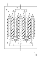
- FIG. 1 is a schematic cross-sectional view of a lithium ion secondary battery according to an embodiment of the present invention.
- FIG. 2 is a graph showing the relationship of 2s discharge power to A / B in the lithium ion secondary battery according to the example.
- FIG. 3 is a graph showing a relationship of 2s charging power with respect to A / B in the lithium ion secondary battery according to the example.
- the lithium ion secondary battery 100 (power storage device) according to the present embodiment mainly includes an electrode assembly 50, a container 70, and leads 7 and 8 connected to the electrode assembly 50. Yes.
- the electrode assembly 50 includes a plurality of negative electrodes 10, positive electrodes 20, separators 30, and electrode protection layers 40.
- the negative electrodes 10 and the positive electrodes 20 are alternately stacked with the separators 30 disposed between them.
- the electrode protective layer 40 is arrange
- the negative electrode 10 has a negative electrode metal foil 12 and a negative electrode active material layer 14 formed on both surfaces of the negative electrode metal foil 12.
- the negative electrode metal foil 12 has a tab portion 12a where the negative electrode active material layer 14 is not formed.
- the negative electrode metal foil 12 is made of a conductive material.
- An example of the material of the negative electrode metal foil 12 is a metal material such as stainless steel, titanium, nickel, aluminum, or copper, or a conductive resin.
- copper is suitable as the material for the negative electrode metal foil 12.
- the thickness of the negative electrode metal foil 12 is not particularly limited, but can be, for example, 5 to 25 ⁇ m. Further, the thickness of the negative electrode active material layer 14 is not particularly limited, but may be, for example, 40 to 100 ⁇ m.
- the negative electrode active material layer 14 includes a negative electrode active material and a binder, and may include a conductive aid as necessary.
- Examples of the negative electrode active material are a carbonaceous material that can occlude and release lithium, an element that can be alloyed with lithium, an elemental compound that has an element that can be alloyed with lithium, or a polymer material.
- Examples of the carbonaceous material are non-graphitizable carbon, artificial graphite, coke, graphite, glassy carbon, organic polymer compound fired body, carbon fiber, activated carbon, or carbon black.
- the organic polymer compound fired body refers to a material obtained by firing and carbonizing a polymer material such as phenols and furans at an appropriate temperature.
- elements that can be alloyed with lithium are Na, K, Rb, Cs, Fr, Be, Mg, Ca, Sr, Ba, Ra, Ti, Ag, Zn, Cd, Al, Ga, 1n, Si, Ge. , Sn, Pb, Sb, Bi.
- the element that can be alloyed with lithium is preferably silicon (Si) or tin (Sn).
- Examples of element compound having lithium can be alloyed elements, ZnLiAl, AlSb, SiB 4, SiB 6, Mg 2 Si, Mg 2 Sn, Ni 2 Si, TiSi 2, MoSi 2, CoSi 2, NiSi 2, CaSi 2, CrSi 2, Cu 5 Si , FeSi 2, MnSi 2, NbSi 2, TaSi 2, VSi 2, WSi 2, ZnSi 2, SiC, Si 3 N4, Si 2 N 2 O, SiO v (0 ⁇ v ⁇ 2 ), SnO w (0 ⁇ w ⁇ 2), SnSiO 3 , LiSiO or LiSnO.
- An example of the elemental compound having an element capable of alloying with lithium is preferably a silicon compound or a tin compound.
- An example of the silicon compound is SiO x (0.5 ⁇ x ⁇ 1.5).
- a tin alloy Cu—Sn alloy, Co—Sn alloy, etc.
- the polymer material are polyacetylene and polypyrrole.
- binders are fluorine-containing resins such as polyvinylidene fluoride, polytetrafluoroethylene, and fluororubber, thermoplastic resins such as polypropylene and polyethylene, imide resins such as polyimide and polyamideimide, alkoxysilyl group-containing resins, and styrene-butadiene rubber And synthetic rubbers such as carboxymethylcellulose.
- the amount of the binder can be 1 to 30 parts by mass with respect to 100 parts by mass of the active material.
- Examples of the conductive aid are carbon-based particles such as carbon black, graphite, acetylene black (AB), ketjen black (registered trademark), KB, and vapor grown carbon fiber (Vapor, Grown, Carbon, Fiber: VGCF). These can be added alone or in combination of two or more.
- the amount of the conductive aid used is not particularly limited, but for example, it can be 1 to 30 parts by mass with respect to 100 parts by mass of the active material.
- the negative electrode active material layer 14 prepares a slurry in which a negative electrode active material, a conductive auxiliary (if necessary), a binder, and a binder solvent are mixed, and is applied onto the negative electrode metal foil 12, and then the solvent is dried Can be formed.
- the solvent are N-methylpyrrolidone, acetone, methyl ethyl ketone, cyclohexanone, methyl isobutyl ketone, ethyl acetate, butyl acetate, tetrahydrofuran and dioxane.
- the positive electrode 20 includes a positive electrode metal foil 22 and a positive electrode active material layer 24 formed on both surfaces of the positive electrode metal foil 22. At the end of the positive electrode metal foil 22, there is a tab portion 22 a where the positive electrode active material layer 24 is not formed.
- the positive metal foil 22 is made of a conductive material. An example of the material of the positive electrode metal foil 22 is a metal such as aluminum.
- the positive electrode active material layer 24 includes a positive electrode active material and a binder, and may include a conductive aid as necessary. Examples and blending amounts of the binder and the conductive additive can be the same as those described for the negative electrode 10.
- the positive electrode active material is not particularly limited as long as it is a positive electrode active material for a lithium secondary battery.
- An example of the positive electrode active material is a lithium compound.
- lithium metal composite oxides such as lithium cobalt composite oxide, lithium nickel composite oxide, and lithium manganese composite oxide can be used.
- Other metal compounds or polymer materials can also be used as the positive electrode active material.
- examples of other metal compounds include oxides such as titanium oxide, vanadium oxide, and manganese dioxide, or disulfides such as titanium sulfide and molybdenum sulfide.
- Examples of the polymer material include conductive polymers such as polyaniline and polythiophene.
- the composite metal oxide include LiCo 1/3 Ni 1/3 Mn 1/3 O 2 , LiNi 0.6 Co 0.2 Mn 0.2 O 2 , LiNi 0.5 CO 0.2 Mn 0.3 O 2 , LiCoO 2 , LiNi 0.8 Co 0.2 O 2 , and LiCoMnO 2 can be used.
- the positive electrode active material layer 24 prepares a slurry in which a positive electrode active material, a conductive additive (if necessary), a binder, and a binder solvent are mixed, and is applied onto the positive electrode metal foil 22 to dry the solvent. Can be formed.
- a solvent is the same as that of manufacture of a negative electrode active material layer.
- the separator 30 separates the positive electrode 20 and the negative electrode 10 and allows lithium ions to pass through while preventing a short circuit of current due to contact between both electrodes.
- An example of the separator 30 is a porous film made of synthetic resin such as polytetrafluoroethylene (PEFE), polypropylene (PP), polyethylene terephthalate (PET), or polyethylene (PE), or a porous film made of ceramics.
- the end portion of the separator 30 preferably extends outward from the end surfaces of the positive electrode active material layer 24 and the negative electrode active material layer 14.
- a pair of separators 30 may form a bag so as to surround the negative electrode 10.
- the thickness of the separator 30 can be 10 to 50 ⁇ m.
- the electrode protective layer 40 is provided between the negative electrode 10 and the separator 30 and between the positive electrode 20 and the separator.
- the electrode protective layer 40 is a porous layer having ceramic particles and a binder that bonds the ceramic particles.
- ceramics are alumina, silica and titania.
- the particle size of the ceramic particles can be 0.2 to 2.0 ⁇ m.
- the kind of binder can be made the same as the binder mentioned by the negative electrode.
- the amount of the binder can be, for example, 1 to 30 parts by mass with respect to 100 parts by mass of the ceramic particles.
- the thickness of the electrode protective layer 40 can be set to 0.5 to 30 ⁇ m, for example.
- the electrode protective layer 40 may be fixed to the negative electrode 10 or the positive electrode 20 in advance, or may be fixed to the separator 30, and is not fixed to the positive electrode 20 and the negative electrode 10 and is not fixed to the separator 30. An aspect may be sufficient.
- the electrode protective layer 40 is prepared by preparing a slurry in which ceramic particles, a binder, and a solvent for the binder are mixed, and applying the slurry to the positive electrode 20, the negative electrode 10, the separator 30, or another substrate, and drying the solvent. Can be formed.
- the example of a solvent is the same as that of manufacture of a negative electrode active material layer.
- the container 70 accommodates the electrode assembly 50 and an electrolytic solution (not shown).
- the material and form of the container 70 are not particularly limited, and various known materials such as resins and metals can be used.
- the electrolytic solution includes an electrolyte and a solvent that dissolves the electrolyte.
- the electrolytic solution is impregnated in the negative electrode active material layer 14, the separator 30, and the positive electrode active material layer 24.
- Examples of the electrolyte are lithium salts such as LiBF 4 , LiPF 6 , LiClO 4 , LiAsF 6 , LiCF 3 SO 3 , and LiN (CF 3 SO 2 ) 2 .
- Examples of the solvent are cyclic esters, chain esters, and ethers. Two or more of these solvents can be mixed.
- Examples of cyclic esters are ethylene carbonate, propylene carbonate, butylene carbonate, gamma butyrolactone, vinylene carbonate, 2-methyl-gamma butyrolactone, acetyl-gamma ptyrolactone, gamma valerolactone.
- Examples of the chain esters are methyl carbonate, diethyl carbonate, dibutyl carbonate, dipropyl carbonate, methyl ethyl carbonate, propionic acid alkyl ester, malonic acid dialkyl ester, and acetic acid alkyl ester.
- ethers examples include tetrahydrofuran, 2-methyltetrahydrofuran, 1,4-dioxane, 1,2-dimethoxyethane, 1,2-diethoxyethane, 1,2-dibutoxyethane.
- the concentration of the electrolyte in the electrolytic solution can be, for example, 0.5 to 1.7 mol / L.
- the electrolytic solution may contain a gelling agent.
- the lead 7 is connected to the tab portion 12 a of each negative electrode metal foil 12.
- the lead 8 is connected to the tab portion 22 a of each positive metal foil 22. The ends of the leads 7 and 8 are outside the container 70.
- the N-methylpyrrolidone in the container 70 is derived from the solvent in the slurry used for the production of the negative electrode active material layer 14, the positive electrode active material layer 24, and / or the electrode protective layer 40. Most of the N-methylpyrrolidone is removed when the slurry is dried, but a part of it remains in the layer and is contained in the container of the completed lithium ion secondary battery 100.
- the drying temperature of the slurry containing N-methylpyrrolidone may be increased and / or the drying time may be lengthened.
- the drying temperature is preferably 100 ° C. or higher and preferably 125 ° C. or lower.
- the drying time is preferably 2 hours or more.
- the total mass of N-methylpyrrolidone in the container 70 can be measured by a gas chromatography fluff mass spectrometer (GCMS).
- GCMS gas chromatography fluff mass spectrometer
- the electrolytic solution may be supplied to the GCMS as it is.
- the concentration in the solid matter such as the negative electrode, the positive electrode, the electrode protective layer, and the separator
- the remaining N-methylpyrrolidone is transferred to acetone by applying ultrasonic waves, and then acetone is supplied to the GCMS.
- the lithium ion secondary battery 100 compared with the conventional lithium ion secondary battery in which N-methylpyrrolidone is used as a solvent during the production of the electrode and / or the electrode protective layer, the high-speed charge / discharge characteristics. Excellent. The reason for this is not clear, but it is conceivable that, for example, since the amount of residual N-methylpyrrolidone is small, a film formed on the negative electrode surface due to N-methylpyrrolidone is reduced.
- the present invention is not limited to the above embodiment, and various modifications can be made.
- the electrode protection layer 40 is provided between both the negative electrode 10 and the separator 30 and between the negative electrode 10 and the separator 30, but electrode protection is provided only between either one. It can be implemented even if the layer 40 is provided.
- Example 1 Manufacture of negative electrode
- Graphite powder negative electrode active material: particle size D50: 20 ⁇ m
- SBR styrene butadiene rubber
- CMC carboxymethyl cellulose
- LiNi 0.5 Co 0.2 Mn 0.3 O 2 particle diameter D50: 10 ⁇ m
- acetylene black acetylene black
- PVDF polyvinylidene fluoride
- This slurry was applied to one side of an aluminum foil, the solvent was dried on a hot plate at 80 ° C. for 30 minutes, pressed, and further heated at 120 ° C. for 3 hours.
- Electrode protective layer thickness 5 ⁇ m
- Alumina particles D50: 0.5 ⁇ m
- PVDF polyvinylidene fluoride
- a solvent N-methylpyrrolidone
- a polyethylene porous sheet was sandwiched between the positive electrode and the negative electrode to obtain a laminate.
- This laminated body was accommodated in a case in which both surfaces of an aluminum foil were laminated with a resin. Further, an electrolyte solution was supplied into the case, and then the case was sealed to obtain a plurality of lithium ion secondary batteries.
- the electrolytic solution contained a solvent and an electrolyte (1 mol / dm 3 LiPF 6 ), and the solvent contained ethylene carbonate, ethyl methyl carbonate, dimethyl carbonate, and fluoroethylene carbonate at a mass ratio of 30:30:40. .
- the total mass B of the negative electrode active material in each battery was 84.9 mg.
- Example 2 The drying conditions after pressing the positive electrode, the negative electrode, and the electrode protective layer were the same as in Example 1 except that the drying conditions were 120 ° C. and 6 hours. Moreover, the total mass B of the negative electrode active material in each battery was 84.1 mg.
- Example 1 The drying conditions after pressing the positive electrode, the negative electrode, and the electrode protective layer were the same as in Example 1 except that the drying conditions were 100 ° C. and 3 hours. Moreover, the total mass B of the negative electrode active material in each battery was 84.4 mg.
Landscapes
- Chemical & Material Sciences (AREA)
- Engineering & Computer Science (AREA)
- Chemical Kinetics & Catalysis (AREA)
- Electrochemistry (AREA)
- General Chemical & Material Sciences (AREA)
- Manufacturing & Machinery (AREA)
- Materials Engineering (AREA)
- Physics & Mathematics (AREA)
- Condensed Matter Physics & Semiconductors (AREA)
- General Physics & Mathematics (AREA)
- Inorganic Chemistry (AREA)
- Secondary Cells (AREA)
- Battery Electrode And Active Subsutance (AREA)
Abstract
リチウムイオン二次電池100は、正極活物質を有する正極20、負極活物質を有する負極10、正極20と負極10との間に配置されたセパレータ30、正極20及び/又は負極10とセパレータ30との間に配置された電極保護層40、電解液、及び、正極20、負極10、セパレータ30、電極保護層40、及び電解液を収容する容器70を備える。容器70内におけるN-メチルピロリドンの全質量をA、容器70内における負極活物質の全質量をBとしたときに、50ppm≦A/B≦150ppmを満たす。
Description
本発明は、リチウムイオン二次電池に関する。
従来より、電極とセパレータとの間に、電極保護層を設けたリチウムイオン二次電池が知られている。また、電極や電極保護層の形成時にはN-メチルピロリドンを用いることが知られている。
しかしながら、従来の方法では、高速充放電特性が十分ではない。本発明は上記課題に鑑みてなされたものであり、高速充放電特性に優れたリチウムイオン二次電池を提供することを目的とする。
本発明に係るリチウムイオン二次電池は、正極活物質を含む正極、負極活物質を含む負極、前記正極と前記負極との間に配置されたセパレータ、前記正極及び/又は前記負極と、前記セパレータとの間に配置された電極保護層、電解液、及び、前記正極、前記負極、前記セパレータ、前記電極保護層、及び前記電解液を収容する容器を備える。
そして、前記容器内におけるN-メチルピロリドンの全質量をA、前記負極活物質の質量をBとしたときに、50ppm≦A/B≦150ppmである。
そして、前記容器内におけるN-メチルピロリドンの全質量をA、前記負極活物質の質量をBとしたときに、50ppm≦A/B≦150ppmである。
本発明によれば、従来のN-メチルピロリドン(NMP)を用いたリチウムイオン二次電池に比して、高速充放電特性に優れる。残存NMP量が少ないために、N-メチルピロリドンに起因して負極表面に形成される膜が少なくなることが考えられる。この膜は電気抵抗成分となり、リチウムイオン二次電池の充放電特性に影響がある。
また、前記N-メチルピロリドンは、前記電極保護層の製造に用いるスラリー中の溶媒に由来することが好ましい。
本発明によれば、高速充放電特性に優れたリチウムイオン二次電池が提供される。
本発明に掛かる実施形態の一例を、図面を参照して説明する。図1に示すように、本実施形態に掛かるリチウムイオン二次電池100(蓄電装置)は、電極組立体50、容器70、及び、電極組立体50に接続されたリード7、8を主として備えている。
(電極組立体50)
電極組立体50は、負極10、正極20、セパレータ30、及び、電極保護層40をそれぞれ複数有している。負極10及び正極20が、これらの間にそれぞれセパレータ30が配置されつつ、交互に積層されている。また、負極10とセパレータ30との間、及び、正極20とセパレータ30との間に、それぞれ、電極保護層40が配置されている。
電極組立体50は、負極10、正極20、セパレータ30、及び、電極保護層40をそれぞれ複数有している。負極10及び正極20が、これらの間にそれぞれセパレータ30が配置されつつ、交互に積層されている。また、負極10とセパレータ30との間、及び、正極20とセパレータ30との間に、それぞれ、電極保護層40が配置されている。
(負極10)
負極10は、負極金属箔12と、この負極金属箔12の両面に形成された負極活物質層14とを有している。負極金属箔12は、負極活物質層14が形成されていないタブ部12aを有する。
負極10は、負極金属箔12と、この負極金属箔12の両面に形成された負極活物質層14とを有している。負極金属箔12は、負極活物質層14が形成されていないタブ部12aを有する。
負極金属箔12は導電材料からなる。負極金属箔12の材料の例は、ステンレス鋼、チタン、ニッケル、アルミニウム、銅などの金属材料または導電性樹脂である。特に、負極金属箔12の材料として、銅が好適である。負極金属箔12の厚みは特に限定されないが、例えば、5~25μmとすることができる。また、負極活物質層14の厚みも特に限定されないが、例えば、40~100μmとすることができる。
負極活物質層14は、負極活物質、バインダを含み、必用に応じて導電助剤を含むことができる。
負極活物質の例は、リチウムを吸蔵、放出可能な炭素質材料、リチウムと合金化可能な元素、リチウムと合金化可能な元素を有する元素化合物、あるいは高分子材料である。
炭素質材料の例は、難黒鉛化性炭素、人造黒鉛、コークス類、グラファイト類、ガラス状炭素類、有機高分子化合物焼成体、炭素繊維、活性炭あるいはカーボンブラック類である。ここで、有機高分子化合物焼成体とは、フェノール類やフラン類などの高分子材料を適当な温度で焼成して炭素化したものをいう。
リチウムと合金化可能な元素の例は、Na、K、Rb、Cs、Fr、Be、Mg、Ca、Sr、Ba、Ra、Ti、Ag、Zn、Cd、Al、Ga、1n、Si、Ge、Sn、Pb、Sb、Biである。中でも、リチウムと合金化可能な元素は、珪素(Si)または錫(Sn)であるとよい。
リチウムと合金化可能な元素を有する元素化合物の例は、ZnLiAl、AlSb、SiB4、SiB6、Mg2Si、Mg2Sn、Ni2Si、TiSi2、MoSi2、CoSi2、NiSi2、CaSi2、CrSi2、Cu5Si、FeSi2、MnSi2、NbSi2、TaSi2、VSi2、WSi2、ZnSi2、SiC、Si3N4、Si2N2O、SiOv(0<v≦2)、SnOw(0<w≦2)、SnSiO3、LiSiOあるいはLiSnOである。リチウムと合金化反応可能な元素を有する元素化合物の例は、珪素化合物または錫化合物であることがよい。珪素化合物の例は、SiOx(0.5≦x≦1.5)である。錫化合物は、例えば、スズ合金(Cu-Sn合金、Co-Sn合金等)などが使用できる。高分子材料の例は、ポリアセチレン、ポリピロールである。
炭素質材料の例は、難黒鉛化性炭素、人造黒鉛、コークス類、グラファイト類、ガラス状炭素類、有機高分子化合物焼成体、炭素繊維、活性炭あるいはカーボンブラック類である。ここで、有機高分子化合物焼成体とは、フェノール類やフラン類などの高分子材料を適当な温度で焼成して炭素化したものをいう。
リチウムと合金化可能な元素の例は、Na、K、Rb、Cs、Fr、Be、Mg、Ca、Sr、Ba、Ra、Ti、Ag、Zn、Cd、Al、Ga、1n、Si、Ge、Sn、Pb、Sb、Biである。中でも、リチウムと合金化可能な元素は、珪素(Si)または錫(Sn)であるとよい。
リチウムと合金化可能な元素を有する元素化合物の例は、ZnLiAl、AlSb、SiB4、SiB6、Mg2Si、Mg2Sn、Ni2Si、TiSi2、MoSi2、CoSi2、NiSi2、CaSi2、CrSi2、Cu5Si、FeSi2、MnSi2、NbSi2、TaSi2、VSi2、WSi2、ZnSi2、SiC、Si3N4、Si2N2O、SiOv(0<v≦2)、SnOw(0<w≦2)、SnSiO3、LiSiOあるいはLiSnOである。リチウムと合金化反応可能な元素を有する元素化合物の例は、珪素化合物または錫化合物であることがよい。珪素化合物の例は、SiOx(0.5≦x≦1.5)である。錫化合物は、例えば、スズ合金(Cu-Sn合金、Co-Sn合金等)などが使用できる。高分子材料の例は、ポリアセチレン、ポリピロールである。
バインダの例は、ポリフッ化ビニリデン、ポリテトラフルオロエチレン、フッ素ゴム等の含フッ素樹脂、ポリプロピレン、ポリエチレン等の熱可塑性樹脂、ポリイミド、ポリアミドイミド等のイミド系樹脂、アルコキシシリル基含有樹脂、スチレンブタジエンゴム等の合成ゴム、カルボキシメチルセルロース等である。バインダの量は、活物質100質量部に対して、1~30質量部とすることができる。
導電助剤の例は、カーボンブラック、黒鉛、アセチレンブラック(AB) 、ケッチェンブラック(登録商標) (KB) 、気相法炭素繊維(Vapor Grown Carbon Fiber:VGCF) 等の炭素系粒子である。これらは、単独で、または二種以上組み合わせて添加することができる。導電助剤の使用量については、特に限定されないが、例えば、100質量部の活物質に対して、1~30質量部とすることができる。
負極活物質層14は、負極活物質、導電助剤(必要であれば)、バインダ、及び、バインダ用の溶媒を混合したスラリーを準備し、負極金属箔12上に塗布し、その後溶媒を乾燥させることにより形成できる。溶媒の例は、N-メチルピロリドン、アセトン、メチルエチルケトン、シクロヘキサノン、メチルイソブチルケトン、酢酸エチル、酢酸ブチル、テトラヒドロフラン、ジオキサンである。
(正極20)
正極20は、正極金属箔22と、この正極金属箔22の両面に形成された正極活物質層24とを有している。正極金属箔22の端には、正極活物質層24が形成されていないタブ部22aを有する。正極金属箔22は導電材料からなる。正極金属箔22の材料の例は、アルミニウムなどの金属である。
正極20は、正極金属箔22と、この正極金属箔22の両面に形成された正極活物質層24とを有している。正極金属箔22の端には、正極活物質層24が形成されていないタブ部22aを有する。正極金属箔22は導電材料からなる。正極金属箔22の材料の例は、アルミニウムなどの金属である。
正極活物質層24は、正極活物質、バインダを含み、必用に応じて導電助剤を含むことができる。バインダや導電助剤の例及び配合量は、負極10で記載したのと同様とすることができる。
正極活物質は、リチウム二次電池用の正極活物質であれば特に限定されない。正極活物質の例は、リチウム化合物である。例えばリチウムコバルト複合酸化物、リチウムニッケル複合酸化物、リチウムマンガン複合酸化物などのリチウム金属複合酸化物などを用いることができる。また正極活物質として他の金属化合物あるいは高分子材料を用いることもできる。他の金属化合物としては、例えば酸化チタン、酸化バナジウムあるいは二酸化マンガンなどの酸化物、または硫化チタンあるいは硫化モリブデンなどの二硫化物が挙げられる。高分子材料としては例えばポリアニリンあるいはポリチオフェンなどの導電性高分子が挙げられる。
特に正極活物質は、一般式:LiCopNiqMnrO2(p+q+r=1、0<p≦1、0≦q<1、0≦r<1)で表されるリチウム金属複合酸化物を含むことが好ましい。上記複合金属酸化物として、例えばLiCo1/3Ni1/3Mn1/3O2、LiNi0.6Co0.2Mn0.2O2、LiNi0.5CO0.2Mn0.3O2、LiCoO2、LiNi0.8Co0.2O2、LiCoMnO2を用いることができる。
また、正極活物質は、一般式:LiCopNiqMnrDsO2(p+q+r+s=1、0<p≦1、0≦q<1、0≦r<1、0<s<1)で表されるリチウム金属複合酸化物を含むことも好ましい。Dは、Al,Mg,Ti,Sn,Zn,W,Zr,Mo,Fe,Naから成る群から選択される少なくとも1つの元素である。
また、正極活物質は、一般式:LiCopNiqMnrDsO2(p+q+r+s=1、0<p≦1、0≦q<1、0≦r<1、0<s<1)で表されるリチウム金属複合酸化物を含むことも好ましい。Dは、Al,Mg,Ti,Sn,Zn,W,Zr,Mo,Fe,Naから成る群から選択される少なくとも1つの元素である。
正極活物質層24は、正極活物質、導電助剤(必要であれば)、バインダ、及び、バインダ用の溶媒を混合したスラリーを準備し、正極金属箔22上に塗布し、溶媒を乾燥させることにより形成できる。溶媒の例は、負極活物質層の製造と同様である。
(セパレータ30)
セパレータ30は、正極20と負極10とを隔離し、両極の接触による電流の短絡を防止しつつ、リチウムイオンを通過させる。セパレータ30の例は、ポリテトラフルオロエチレン(PEFE)、ポリプロピレン(PP)、ポリエチレンテレフタレート(PET)、あるいはポリエチレン(PE)などの合成樹脂製の多孔質膜、またはセラミックス製の多孔質膜である。
セパレータ30は、正極20と負極10とを隔離し、両極の接触による電流の短絡を防止しつつ、リチウムイオンを通過させる。セパレータ30の例は、ポリテトラフルオロエチレン(PEFE)、ポリプロピレン(PP)、ポリエチレンテレフタレート(PET)、あるいはポリエチレン(PE)などの合成樹脂製の多孔質膜、またはセラミックス製の多孔質膜である。
セパレータ30の端部は、図1に示すように、正極活物質層24及び負極活物質層14の端面よりも外側に延びていることが好ましい。また、一対のセパレータ30が、負極10を取り囲むように袋を形成していても良い。セパレータ30の厚みは、10~50μmとすることができる。
(電極保護層40)
電極保護層40は、負極10とセパレータ30との間、及び、正極20とセパレータとの間にそれぞれ設けられている。電極保護層40は、セラミクス粒子と、セラミクス粒子同士を結合するバインダとを有する、多孔質層である。セラミクスの例は、アルミナ、シリカ、チタニアである。セラミクス粒子の粒径は、0.2~2.0μmとすることができる。バインダの種類は、負極で挙げたバインダと同じとすることができる。バインダの量は、セラミクス粒子100質量部に対して、例えば、1~30質量部とすることができる。電極保護層40の厚みは、例えば、0.5~30μmとすることができる。
電極保護層40は、負極10とセパレータ30との間、及び、正極20とセパレータとの間にそれぞれ設けられている。電極保護層40は、セラミクス粒子と、セラミクス粒子同士を結合するバインダとを有する、多孔質層である。セラミクスの例は、アルミナ、シリカ、チタニアである。セラミクス粒子の粒径は、0.2~2.0μmとすることができる。バインダの種類は、負極で挙げたバインダと同じとすることができる。バインダの量は、セラミクス粒子100質量部に対して、例えば、1~30質量部とすることができる。電極保護層40の厚みは、例えば、0.5~30μmとすることができる。
電極保護層40は、予め負極10又は正極20に固定されていても良いし、セパレータ30に固定されていても良いし、正極20及び負極10に固定されずかつセパレータ30にも固定されていない態様でも良い。
電極保護層40は、セラミック粒子、バインダ、及び、バインダ用の溶媒を混合したスラリーを準備し、正極20、負極10、セパレータ30、あるいは、他の基材等に塗布し、溶媒を乾燥させることにより形成できる。溶媒の例は、負極活物質層の製造と同様である。
(容器70)
容器70は、電極組立体50、及び電解液(図示略)を収容する。容器70の材料や形態は特に限定されず、樹脂、金属などの公知の種々の物を使用できる。
容器70は、電極組立体50、及び電解液(図示略)を収容する。容器70の材料や形態は特に限定されず、樹脂、金属などの公知の種々の物を使用できる。
(電解液)
電解液は、電解質と、この電解質を溶解する溶媒とを含む。電解液は、負極活物質層14、セパレータ30、正極活物質層24内に含浸されている。
電解液は、電解質と、この電解質を溶解する溶媒とを含む。電解液は、負極活物質層14、セパレータ30、正極活物質層24内に含浸されている。
電解質の例は、LiBF4、LiPF6、LiClO4、LiAsF6、LiCF3SO3、LiN(CF3SO2)2等のリチウム塩である。
溶媒の例は、環状エステル類、鎖状エステル類、エーテル類である。これらの溶媒を2種以上混合することもできる。環状エステル類の例は、エチレンカーボネート、プロピレンカーボネート、ブチレンカーボネート、ガンマブチロラクトン、ビニレンカーボネート、2-メチル-ガンマブチロラクトン、アセチル-ガンマプチロラクトン、ガンマバレロラクトンである。鎖状エステル類の例は、メチルカーボネート、ジエチルカーボネート、ジブチルカーボネート、ジプロピルカーボネート、メチルエチルカーボネート、プロピオン酸アルキルエステル、マロン酸ジアルキルエステル、酢酸アルキルエステルである。エーテル類の例は、テトラヒドロフラン、2-メチルテトラヒドロフラン、1,4-ジオキサン、1,2-ジメトキシエタン、1,2-ジエトキシエタン、1,2-ジブトキシエタンである。
電解液における電解質の濃度は、例えば、0.5~1.7mol/Lとすることができる。電解液は、ゲル化剤を含んでいても良い。
(リード)
リード7は各負極金属箔12のタブ部12aに接続されている。リード8は各正極金属箔22のタブ部22aに接続されている。リード7、8の端部は、容器70の外部に出ている。
リード7は各負極金属箔12のタブ部12aに接続されている。リード8は各正極金属箔22のタブ部22aに接続されている。リード7、8の端部は、容器70の外部に出ている。
(容器内のN-メチルピロリドンの濃度)
本実施形態に係るリチウムイオン二次電池においては、容器70内におけるN-メチルピロリドンの全質量をA、容器70内における負極活物質の全質量をBとしたときに、50ppm≦A/B≦150ppmを満たす。75ppm≦A/Bであることができる。また、A/B≦130ppmであることができる。
本実施形態に係るリチウムイオン二次電池においては、容器70内におけるN-メチルピロリドンの全質量をA、容器70内における負極活物質の全質量をBとしたときに、50ppm≦A/B≦150ppmを満たす。75ppm≦A/Bであることができる。また、A/B≦130ppmであることができる。
容器70内のN-メチルピロリドンは、負極活物質層14、正極活物質層24、及び/又は、電極保護層40の製造に用いるスラリー中の溶媒に由来する。大部分のN-メチルピロリドンはスラリーの乾燥時に除去されるが、一部が層中に残存し、完成したリチウムイオン二次電池100の容器内に含まれることになる。容器内のN-メチルピロリドンの濃度を十分に低くするにはN-メチルピロリドンを含むスラリーの乾燥温度を高くし、及び/又は、乾燥時間を長くすればよい。乾燥温度は、100℃以上が好ましく125℃以下が好ましい。乾燥時間は、2時間以上が好ましい。
容器70内のN-メチルピロリドンの全質量量は、ガスクロマトフラフ質量分析計(GCMS)により測定できる。例えば、電解液中の濃度の測定時には電解液をそのままGCMSに供給すればよいし、負極、正極、電極保護層、及び、セパレータ等の固体物中の濃度の測定時には、これらをアセトンに浸しながら超音波を当てて残存するN-メチルピロリドンをアセトンに移行させた後、アセトンをGCMSに供給すればよい。
(作用効果)
本実施形態にかかるリチウムイオン二次電池100によれば、N-メチルピロリドンを電極及び/又は電極保護層製造時の溶媒に用いた従来のリチウムイオン二次電池に比して、高速充放電特性に優れる。その理由は明らかではないが、例えば、残存N-メチルピロリドン量が少ないために、N-メチルピロリドンに起因して負極表面に形成される膜が少なくなることが考えられる。
本実施形態にかかるリチウムイオン二次電池100によれば、N-メチルピロリドンを電極及び/又は電極保護層製造時の溶媒に用いた従来のリチウムイオン二次電池に比して、高速充放電特性に優れる。その理由は明らかではないが、例えば、残存N-メチルピロリドン量が少ないために、N-メチルピロリドンに起因して負極表面に形成される膜が少なくなることが考えられる。
本発明は上記実施形態に限定されず、様々な変形態様を取ることが出来る。
例えば、上記実施形態では、負極10とセパレータ30との間、及び、負極10とセパレータ30との間の両方に、電極保護層40が設けられているが、いずれか一方の間にのみ電極保護層40が設けられていても実施可能である。
例えば、上記実施形態では、負極10とセパレータ30との間、及び、負極10とセパレータ30との間の両方に、電極保護層40が設けられているが、いずれか一方の間にのみ電極保護層40が設けられていても実施可能である。
(実施例1)
(負極の製造)
黒鉛粉(負極活物質:粒径D50:20μm)、スチレンブタジエンゴム(SBR)、カルボキシメチルセルロース(CMC)を、それぞれ、98:1:1の質量比で混合し、さらに、溶媒(イオン交換水)を加えてスラリーを得た。このスラリーを、銅箔の片面に成膜し、溶媒をホットプレートにより80℃で15分乾燥させ、プレスし、さらに、120℃で3時間加熱した。
(負極の製造)
黒鉛粉(負極活物質:粒径D50:20μm)、スチレンブタジエンゴム(SBR)、カルボキシメチルセルロース(CMC)を、それぞれ、98:1:1の質量比で混合し、さらに、溶媒(イオン交換水)を加えてスラリーを得た。このスラリーを、銅箔の片面に成膜し、溶媒をホットプレートにより80℃で15分乾燥させ、プレスし、さらに、120℃で3時間加熱した。
(正極の製造)
LiNi0.5Co0.2Mn0.3O2(粒径D50:10μm)、アセチレンブラック、及び、ポリフッ化ビニリデン(PVDF)を、94:3:3の質量比で混合し、さらに、溶媒(N-メチルピロリドン)を加えてスラリーを得た。このスラリーを、アルミニウム箔の片面に塗布し、溶媒をホットプレートにより80℃で30分乾燥させ、プレスし、さらに、120℃で3時間加熱した。
LiNi0.5Co0.2Mn0.3O2(粒径D50:10μm)、アセチレンブラック、及び、ポリフッ化ビニリデン(PVDF)を、94:3:3の質量比で混合し、さらに、溶媒(N-メチルピロリドン)を加えてスラリーを得た。このスラリーを、アルミニウム箔の片面に塗布し、溶媒をホットプレートにより80℃で30分乾燥させ、プレスし、さらに、120℃で3時間加熱した。
(電極保護層(厚み5μm)の形成)
アルミナ粒子(D50:0.5μm)、ポリフッ化ビニリデン(PVDF)をそれぞれ96:4の質量比で混合し、さらに、溶媒(N-メチルピロリドン)を加えてスラリーを得た。このスラリーを、正極及び負極の両面に成膜し、溶媒をホットプレートにより80℃で15分乾燥させ、プレスし、さらに、120℃で3時間加熱し、正極及び負極の両面に電極保護層を設けた。
アルミナ粒子(D50:0.5μm)、ポリフッ化ビニリデン(PVDF)をそれぞれ96:4の質量比で混合し、さらに、溶媒(N-メチルピロリドン)を加えてスラリーを得た。このスラリーを、正極及び負極の両面に成膜し、溶媒をホットプレートにより80℃で15分乾燥させ、プレスし、さらに、120℃で3時間加熱し、正極及び負極の両面に電極保護層を設けた。
(電池の製造)
ポリエチレン多孔質シートを、正極及び負極の間に挟んで、積層体を得た。この積層体を、アルミニウム箔の両面を樹脂でラミネートしたケース内に収容し、さらに、ケース内に電解液を供給し、その後、ケースをシールし、複数のリチウムイオン二次電池を得た。電解液は、溶媒と電解質(1mol/dm3のLiPF6)とを含み、溶媒は、エチレンカーボネート、エチルメチルカーボネート、ジメチルカーボネート、フルオロエチレンカーボネートを、質量比において30:30:40で含んでいた。また、各電池中の負極活物質の全質量Bは84.9mgであった。
ポリエチレン多孔質シートを、正極及び負極の間に挟んで、積層体を得た。この積層体を、アルミニウム箔の両面を樹脂でラミネートしたケース内に収容し、さらに、ケース内に電解液を供給し、その後、ケースをシールし、複数のリチウムイオン二次電池を得た。電解液は、溶媒と電解質(1mol/dm3のLiPF6)とを含み、溶媒は、エチレンカーボネート、エチルメチルカーボネート、ジメチルカーボネート、フルオロエチレンカーボネートを、質量比において30:30:40で含んでいた。また、各電池中の負極活物質の全質量Bは84.9mgであった。
(実施例2)
正極、負極、及び、電極保護層のプレス後の乾燥条件を、120℃及び6時間とする以外は実施例1と同様にした。また、各電池中の負極活物質の全質量Bは、84.1mgであった。
正極、負極、及び、電極保護層のプレス後の乾燥条件を、120℃及び6時間とする以外は実施例1と同様にした。また、各電池中の負極活物質の全質量Bは、84.1mgであった。
(比較例1)
正極、負極、及び、電極保護層のプレス後の乾燥条件を、100℃及び3時間とする以外は実施例1と同様にした。また、各電池中の負極活物質の全質量Bは、84.4mgであった。
正極、負極、及び、電極保護層のプレス後の乾燥条件を、100℃及び3時間とする以外は実施例1と同様にした。また、各電池中の負極活物質の全質量Bは、84.4mgであった。
(容器内のN-メチルピロリドンの濃度)
各実施例及び比較例の電池の容器内のN-メチルピロリドンの質量Aを、GCMSにて測定した。実施例1、2、比較例1の順に、A/Bは、95ppm、131ppm、403ppmであった。
各実施例及び比較例の電池の容器内のN-メチルピロリドンの質量Aを、GCMSにて測定した。実施例1、2、比較例1の順に、A/Bは、95ppm、131ppm、403ppmであった。
(高速充放電特性の評価)
充電状態(State Of Charge:SOC)が10%の各電池に対して、25℃で2秒間に放電できる単位負極活物質質量あたりの電力を測定した。得られた電力を、A/Bに対してプロットした結果を図2に示す。
充電状態(SOC)が80%の各電池に対して、25℃で2秒間に充電できる単位負極活物質質量あたりの電力を測定した。得られた電力を、A/Bに対してプロットした結果を図3に示す。
充電状態(State Of Charge:SOC)が10%の各電池に対して、25℃で2秒間に放電できる単位負極活物質質量あたりの電力を測定した。得られた電力を、A/Bに対してプロットした結果を図2に示す。
充電状態(SOC)が80%の各電池に対して、25℃で2秒間に充電できる単位負極活物質質量あたりの電力を測定した。得られた電力を、A/Bに対してプロットした結果を図3に示す。
50ppm≦A/B≦150ppmを満たす実施例では、急速充放電特性が優れていることが確認された。
10…負極、20…正極、30…セパレータ、40…電極保護層、70…容器、100…リチウムイオン二次電池。
Claims (2)
- 正極活物質を有する正極、
負極活物質を有する負極、
前記正極と前記負極との間に配置されたセパレータ、
前記正極及び/又は前記負極と、前記セパレータとの間に配置された電極保護層、
電解液、及び、
前記正極、前記負極、前記セパレータ、前記電極保護層、及び前記電解液を収容する容器を備え、
前記容器内におけるN-メチルピロリドンの全質量をA、前記容器内における前記負極活物質の全質量をBとしたときに、50ppm≦A/B≦150ppmを満たす、リチウムイオン二次電池。 - 前記N-メチルピロリドンは、前記電極保護層の製造に用いるスラリー中の溶媒に由来する請求項1に記載のリチウムイオン二次電池。
Applications Claiming Priority (2)
| Application Number | Priority Date | Filing Date | Title |
|---|---|---|---|
| JP2013153837A JP5673751B2 (ja) | 2013-07-24 | 2013-07-24 | リチウムイオン二次電池 |
| JP2013-153837 | 2013-07-24 |
Publications (1)
| Publication Number | Publication Date |
|---|---|
| WO2015011965A1 true WO2015011965A1 (ja) | 2015-01-29 |
Family
ID=52393022
Family Applications (1)
| Application Number | Title | Priority Date | Filing Date |
|---|---|---|---|
| PCT/JP2014/062519 Ceased WO2015011965A1 (ja) | 2013-07-24 | 2014-05-09 | リチウムイオン二次電池 |
Country Status (2)
| Country | Link |
|---|---|
| JP (1) | JP5673751B2 (ja) |
| WO (1) | WO2015011965A1 (ja) |
Families Citing this family (1)
| Publication number | Priority date | Publication date | Assignee | Title |
|---|---|---|---|---|
| JP2018041675A (ja) * | 2016-09-09 | 2018-03-15 | 株式会社豊田自動織機 | リチウムイオン二次電池 |
Citations (10)
| Publication number | Priority date | Publication date | Assignee | Title |
|---|---|---|---|---|
| JPH09237623A (ja) * | 1996-02-28 | 1997-09-09 | Ricoh Co Ltd | 非水電解質二次電池 |
| JPH10334888A (ja) * | 1997-05-29 | 1998-12-18 | Ricoh Co Ltd | 非水電解質二次電池用負極および該負極を使用した非水電解質二次電池 |
| JP2002252038A (ja) * | 2001-02-22 | 2002-09-06 | Sony Corp | 非水電解液電池及びその製造方法 |
| JP2005166331A (ja) * | 2003-12-01 | 2005-06-23 | Shin Kobe Electric Mach Co Ltd | リチウムイオン蓄電池の製造方法 |
| JP2006269321A (ja) * | 2005-03-25 | 2006-10-05 | Matsushita Electric Ind Co Ltd | 捲回型非水電解液二次電池 |
| JP2007035770A (ja) * | 2005-07-25 | 2007-02-08 | Tdk Corp | 電気化学素子用電極の製造方法および電気化学素子の製造方法 |
| JP2008091192A (ja) * | 2006-10-02 | 2008-04-17 | Matsushita Electric Ind Co Ltd | リチウム二次電池用極板の製造方法、その製造法を用いたリチウム二次電池用極板とリチウム二次電池 |
| JP2012190552A (ja) * | 2011-03-08 | 2012-10-04 | Toyota Motor Corp | リチウムイオン二次電池の製造方法 |
| JP2013065409A (ja) * | 2011-09-15 | 2013-04-11 | Toyota Motor Corp | リチウム二次電池 |
| JP2013254698A (ja) * | 2012-06-08 | 2013-12-19 | Toyota Industries Corp | 二次電池用電極の製造方法及び非水系二次電池 |
-
2013
- 2013-07-24 JP JP2013153837A patent/JP5673751B2/ja not_active Expired - Fee Related
-
2014
- 2014-05-09 WO PCT/JP2014/062519 patent/WO2015011965A1/ja not_active Ceased
Patent Citations (10)
| Publication number | Priority date | Publication date | Assignee | Title |
|---|---|---|---|---|
| JPH09237623A (ja) * | 1996-02-28 | 1997-09-09 | Ricoh Co Ltd | 非水電解質二次電池 |
| JPH10334888A (ja) * | 1997-05-29 | 1998-12-18 | Ricoh Co Ltd | 非水電解質二次電池用負極および該負極を使用した非水電解質二次電池 |
| JP2002252038A (ja) * | 2001-02-22 | 2002-09-06 | Sony Corp | 非水電解液電池及びその製造方法 |
| JP2005166331A (ja) * | 2003-12-01 | 2005-06-23 | Shin Kobe Electric Mach Co Ltd | リチウムイオン蓄電池の製造方法 |
| JP2006269321A (ja) * | 2005-03-25 | 2006-10-05 | Matsushita Electric Ind Co Ltd | 捲回型非水電解液二次電池 |
| JP2007035770A (ja) * | 2005-07-25 | 2007-02-08 | Tdk Corp | 電気化学素子用電極の製造方法および電気化学素子の製造方法 |
| JP2008091192A (ja) * | 2006-10-02 | 2008-04-17 | Matsushita Electric Ind Co Ltd | リチウム二次電池用極板の製造方法、その製造法を用いたリチウム二次電池用極板とリチウム二次電池 |
| JP2012190552A (ja) * | 2011-03-08 | 2012-10-04 | Toyota Motor Corp | リチウムイオン二次電池の製造方法 |
| JP2013065409A (ja) * | 2011-09-15 | 2013-04-11 | Toyota Motor Corp | リチウム二次電池 |
| JP2013254698A (ja) * | 2012-06-08 | 2013-12-19 | Toyota Industries Corp | 二次電池用電極の製造方法及び非水系二次電池 |
Also Published As
| Publication number | Publication date |
|---|---|
| JP5673751B2 (ja) | 2015-02-18 |
| JP2015026452A (ja) | 2015-02-05 |
Similar Documents
| Publication | Publication Date | Title |
|---|---|---|
| CN101436659B (zh) | 用于锂离子二次电池的正极、其制造方法及锂离子二次电池 | |
| US9343775B2 (en) | Nonaqueous electrolyte composition and nonaqueous electrolyte battery | |
| JP7158592B2 (ja) | 炭素系ハイブリッド負極を備える二次電池の寿命特性の予測方法 | |
| JP7009016B2 (ja) | リチウム二次電池用正極活物質、この製造方法、これを含むリチウム二次電池用正極及びリチウム二次電池 | |
| JP6252858B2 (ja) | リチウムイオン二次電池用正極及びリチウムイオン二次電池 | |
| JP2015011922A (ja) | リチウムイオン二次電池用負極及びリチウムイオン二次電池 | |
| JP6061143B2 (ja) | リチウムイオン二次電池用正極及びリチウムイオン二次電池 | |
| JP5482858B2 (ja) | リチウムイオン二次電池 | |
| JP6048312B2 (ja) | リチウムイオン二次電池用負極及びリチウムイオン二次電池 | |
| JP5557067B1 (ja) | リチウムイオン二次電池用正極及びリチウムイオン二次電池 | |
| JP2014082084A (ja) | リチウムイオン二次電池 | |
| JP5534377B2 (ja) | リチウムイオン二次電池用正極活物質およびそれを有するリチウムイオン二次電池 | |
| JP5713071B2 (ja) | リチウムイオン二次電池 | |
| JP2014149989A (ja) | リチウムイオン二次電池用活物質、それを有するリチウムイオン二次電池用電極及びリチウムイオン二次電池 | |
| JP6160521B2 (ja) | 蓄電装置 | |
| WO2016151980A1 (ja) | 非水電解質二次電池用負極及び非水電解質二次電池 | |
| JP2016115656A (ja) | リチウムイオン二次電池 | |
| JP6011634B2 (ja) | 非水電解質二次電池 | |
| JP6016029B2 (ja) | リチウムイオン二次電池用正極及びリチウムイオン二次電池 | |
| JP5673751B2 (ja) | リチウムイオン二次電池 | |
| KR20210053747A (ko) | 탄소계 기반 하이브리드 음극의 정량적 분석 방법 | |
| JP5610031B1 (ja) | リチウムイオン二次電池用正極及びリチウムイオン二次電池 | |
| JP2015082480A (ja) | リチウムイオン二次電池用正極及びリチウムイオン二次電池 | |
| JP5999430B2 (ja) | リチウムイオン二次電池用正極活物質およびそれを有するリチウムイオン二次電池 | |
| CN112913049A (zh) | 非水电解质二次电池用正极及非水电解质二次电池 |
Legal Events
| Date | Code | Title | Description |
|---|---|---|---|
| 121 | Ep: the epo has been informed by wipo that ep was designated in this application |
Ref document number: 14829337 Country of ref document: EP Kind code of ref document: A1 |
|
| NENP | Non-entry into the national phase |
Ref country code: DE |
|
| 122 | Ep: pct application non-entry in european phase |
Ref document number: 14829337 Country of ref document: EP Kind code of ref document: A1 |