WO2014208744A1 - 光レセプタクル、フェルールおよびプラグフェルール - Google Patents
光レセプタクル、フェルールおよびプラグフェルール Download PDFInfo
- Publication number
- WO2014208744A1 WO2014208744A1 PCT/JP2014/067227 JP2014067227W WO2014208744A1 WO 2014208744 A1 WO2014208744 A1 WO 2014208744A1 JP 2014067227 W JP2014067227 W JP 2014067227W WO 2014208744 A1 WO2014208744 A1 WO 2014208744A1
- Authority
- WO
- WIPO (PCT)
- Prior art keywords
- ferrule
- optical receptacle
- foreign matter
- plug
- fiber stub
- Prior art date
- Legal status (The legal status is an assumption and is not a legal conclusion. Google has not performed a legal analysis and makes no representation as to the accuracy of the status listed.)
- Ceased
Links
Images








Classifications
-
- G—PHYSICS
- G02—OPTICS
- G02B—OPTICAL ELEMENTS, SYSTEMS OR APPARATUS
- G02B6/00—Light guides; Structural details of arrangements comprising light guides and other optical elements, e.g. couplings
- G02B6/24—Coupling light guides
- G02B6/36—Mechanical coupling means
- G02B6/38—Mechanical coupling means having fibre to fibre mating means
- G02B6/3807—Dismountable connectors, i.e. comprising plugs
- G02B6/3833—Details of mounting fibres in ferrules; Assembly methods; Manufacture
- G02B6/3847—Details of mounting fibres in ferrules; Assembly methods; Manufacture with means preventing fibre end damage, e.g. recessed fibre surfaces
-
- G—PHYSICS
- G02—OPTICS
- G02B—OPTICAL ELEMENTS, SYSTEMS OR APPARATUS
- G02B6/00—Light guides; Structural details of arrangements comprising light guides and other optical elements, e.g. couplings
- G02B6/24—Coupling light guides
- G02B6/26—Optical coupling means
- G02B6/262—Optical details of coupling light into, or out of, or between fibre ends, e.g. special fibre end shapes or associated optical elements
-
- G—PHYSICS
- G02—OPTICS
- G02B—OPTICAL ELEMENTS, SYSTEMS OR APPARATUS
- G02B6/00—Light guides; Structural details of arrangements comprising light guides and other optical elements, e.g. couplings
- G02B6/24—Coupling light guides
- G02B6/36—Mechanical coupling means
- G02B6/38—Mechanical coupling means having fibre to fibre mating means
- G02B6/3807—Dismountable connectors, i.e. comprising plugs
- G02B6/381—Dismountable connectors, i.e. comprising plugs of the ferrule type, e.g. fibre ends embedded in ferrules, connecting a pair of fibres
- G02B6/3825—Dismountable connectors, i.e. comprising plugs of the ferrule type, e.g. fibre ends embedded in ferrules, connecting a pair of fibres with an intermediate part, e.g. adapter, receptacle, linking two plugs
-
- G—PHYSICS
- G02—OPTICS
- G02B—OPTICAL ELEMENTS, SYSTEMS OR APPARATUS
- G02B6/00—Light guides; Structural details of arrangements comprising light guides and other optical elements, e.g. couplings
- G02B6/24—Coupling light guides
- G02B6/36—Mechanical coupling means
- G02B6/38—Mechanical coupling means having fibre to fibre mating means
- G02B6/3807—Dismountable connectors, i.e. comprising plugs
- G02B6/3833—Details of mounting fibres in ferrules; Assembly methods; Manufacture
- G02B6/3846—Details of mounting fibres in ferrules; Assembly methods; Manufacture with fibre stubs
-
- G—PHYSICS
- G02—OPTICS
- G02B—OPTICAL ELEMENTS, SYSTEMS OR APPARATUS
- G02B6/00—Light guides; Structural details of arrangements comprising light guides and other optical elements, e.g. couplings
- G02B6/24—Coupling light guides
- G02B6/36—Mechanical coupling means
- G02B6/38—Mechanical coupling means having fibre to fibre mating means
- G02B6/3807—Dismountable connectors, i.e. comprising plugs
- G02B6/3833—Details of mounting fibres in ferrules; Assembly methods; Manufacture
- G02B6/3863—Details of mounting fibres in ferrules; Assembly methods; Manufacture fabricated by using polishing techniques
-
- G—PHYSICS
- G02—OPTICS
- G02B—OPTICAL ELEMENTS, SYSTEMS OR APPARATUS
- G02B6/00—Light guides; Structural details of arrangements comprising light guides and other optical elements, e.g. couplings
- G02B6/24—Coupling light guides
- G02B6/36—Mechanical coupling means
- G02B6/38—Mechanical coupling means having fibre to fibre mating means
- G02B6/3807—Dismountable connectors, i.e. comprising plugs
- G02B6/3833—Details of mounting fibres in ferrules; Assembly methods; Manufacture
- G02B6/3866—Devices, tools or methods for cleaning connectors
-
- G—PHYSICS
- G02—OPTICS
- G02B—OPTICAL ELEMENTS, SYSTEMS OR APPARATUS
- G02B6/00—Light guides; Structural details of arrangements comprising light guides and other optical elements, e.g. couplings
- G02B6/24—Coupling light guides
- G02B6/36—Mechanical coupling means
- G02B6/38—Mechanical coupling means having fibre to fibre mating means
- G02B6/3807—Dismountable connectors, i.e. comprising plugs
- G02B6/3873—Connectors using guide surfaces for aligning ferrule ends, e.g. tubes, sleeves, V-grooves, rods, pins, balls
- G02B6/3874—Connectors using guide surfaces for aligning ferrule ends, e.g. tubes, sleeves, V-grooves, rods, pins, balls using tubes, sleeves to align ferrules
Definitions
- aspects of the present invention generally relate to optical receptacles, ferrules, and plug ferrules.
- An optical receptacle is used as a component for optically connecting an optical fiber connector to an optical element such as a light receiving element or a light emitting element in an optical module of an optical communication transceiver (see, for example, Patent Document 1).
- an optical element such as a light receiving element or a light emitting element in an optical module of an optical communication transceiver (see, for example, Patent Document 1).
- a plurality of optical fiber connectors may be connected to each other via an adapter without using an optical receptacle.
- the basic characteristic of the optical receptacle is that the optical element and the optical fiber connector are optically connected.
- a lateral load is applied to the optical fiber connector inserted into the optical receptacle, so that
- One of the important characteristics is a loss generally referred to as a Wiggle loss due to a shift in the center axis of the plug ferrule in the fiber stub and the optical fiber connector.
- the optical receptacles and plug ferrules are connected to each other in order to avoid loss during connection and damage to the fiber that may cause problems in appearance.
- the end surface to be cleaned is performed.
- the tip of the fiber stub is used to prevent foreign matter on the outer periphery from moving to the center of the fiber stub during the process of repeatedly inserting and removing the plug ferrule into the optical receptacle.
- step difference in can be considered (for example, refer patent document 3).
- An aspect of the present invention has been made to solve the above-described problem.
- the plug ferrule When the plug ferrule is repeatedly inserted into and removed from the optical receptacle or adapter, the foreign matter on the outer periphery of the fiber stub or the outer periphery of the plug ferrule becomes the end surface of the fiber stub or the plug ferrule.
- An object of the present invention is to provide an optical receptacle capable of preventing loss due to movement to the center portion of the end face, or reducing the wiggle loss by maintaining the length that the sleeve holds the fiber stub.
- a fiber stub having a ferrule containing an optical fiber for conducting light, a holder for holding the fiber stub, and holding the tip of the fiber stub at one end, A sleeve capable of holding a plug ferrule to be inserted into the optical receptacle at the other end, and the ferrule has an end surface polished to a convex spherical shape on the side connected to the plug ferrule of the ferrule.
- an optical receptacle characterized by having a foreign matter movement restraining portion for restraining the movement of foreign matter that moves from the outer peripheral portion of the ferrule toward the center portion of the end face by insertion and extraction.
- FIG. 1 is a schematic cross-sectional view of an optical receptacle showing a first embodiment of the present invention.
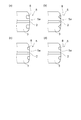
- 2 (a) to 2 (d) are schematic cross-sectional views of a recess formed on an end surface polished to a convex spherical surface of a fiber stub in the first embodiment of the present invention.
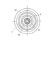
- FIG. 3 is a schematic view of an end face connected to a fiber stub plug ferrule in an optical receptacle showing a second embodiment of the present invention.
- FIG. 4 is a schematic cross-sectional view of a recess formed in the end face of a fiber stub in the third embodiment of the present invention.
- FIG. 5 is a schematic view showing a state of an end face on the side connected to a plug ferrule of a fiber stub showing a fourth embodiment of the present invention.
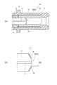
- FIG. 6A and FIG. 6B are schematic cross-sectional views of an optical receptacle showing a fifth embodiment of the present invention.
- FIG. 7A and FIG. 7B are schematic cross-sectional views of an optical receptacle showing a sixth embodiment of the present invention.
- FIG. 8A and FIG. 8B are schematic cross-sectional views of an optical receptacle showing a seventh embodiment of the present invention.
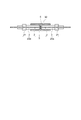
- FIG. 9 is a schematic cross-sectional view showing a state in which a plurality of plug ferrules are connected to each other via a sleeve.
- FIG. 9 is a schematic cross-sectional view showing a state in which a plurality of plug ferrules are connected to each other via a sleeve.
- FIG. 10A to FIG. 10D are tables illustrating an example of the result of the study on the surface roughness performed by the present inventor.
- FIG. 11 is a graph illustrating another example of the result of the study on surface roughness performed by the present inventor.
- FIG. 12A and FIG. 12B are schematic views showing a sample used for the study on the concave portion implemented by the present inventor.
- FIG. 13 is a graph illustrating an example of a result of a study on a recess performed by the present inventor.
- FIG. 14 is a table illustrating an example of the result of the study on the surface roughness of the inner surface of the recess performed by the present inventor.
- a fiber stub having a ferrule containing an optical fiber for conducting light, a holder for holding the fiber stub, and holding the tip of the fiber stub at one end and at the other end.
- a sleeve capable of holding a plug ferrule to be inserted into an optical receptacle, and the ferrule is inserted into and removed from the end surface of the ferrule connected to the plug ferrule by polishing the plug ferrule.
- An optical receptacle characterized by having a foreign matter movement restraining portion for restraining the movement of foreign matter moving from the outer peripheral portion of the ferrule toward the center portion of the end face.
- a second invention is the optical receptacle according to the first invention, wherein the foreign substance movement suppressing portion has a concave portion provided in the end face and continuous in a circumferential shape.
- a third invention is the optical receptacle according to the second invention, wherein the concave portion is located outside a portion where the ferrule and the plug ferrule contact when the plug ferrule is inserted.
- optical receptacle it is possible to prevent the circumferential concave portion from interfering with the connection between the fiber stub and the plug ferrule.
- a fourth invention is an optical receptacle according to the second invention, wherein a plurality of the recesses are provided.
- the fifth invention is the optical receptacle according to the second invention, wherein the surface roughness of the inner surface of the recess is larger than the surface roughness of the region other than the recess.
- optical receptacle foreign matter can be accommodated in the circumferential recess, and movement of the foreign matter that moves toward the center of the end face of the ferrule can be suppressed.
- the foreign matter movement suppressing portion has a first portion that is not in direct contact with the plug ferrule on an end surface of the ferrule on the side connected to the plug ferrule.
- the average height of the surface of the first portion is 0.305 or more, and the skewness of the surface of the first portion is ⁇ 0.2 or less.
- the first portion having an average height of 0.305 or more and a skewness of ⁇ 0.2 or less can catch foreign matter and suppress the movement of the foreign matter.
- a seventh invention is the optical receptacle according to the sixth invention, wherein at least a part of the first part has a tapered shape connected to an outer peripheral part of the fiber stub.
- the fiber stub can be easily press-fitted into the holder.
- the second portion of the ferrule on the side connected to the plug ferrule directly contacts the plug ferrule, and the second portion is more inferior to the first portion.
- optical receptacle it is possible to more reliably suppress the foreign matter from moving toward the center of the end face of the ferrule.
- the distance between the end surface of the second portion and the portion where the second portion is connected to the first portion is 0.2 mm or less. It is an optical receptacle characterized by being.
- optical receptacle it is possible to prevent the foreign matter from moving toward the center of the end face of the ferrule and to ensure the anti-wiggle performance.
- a tenth invention is a ferrule containing an optical fiber for conducting light, It is characterized by having a foreign substance movement suppressing part that suppresses movement of a foreign substance moving from the outer peripheral part toward the center part of the end face by insertion / extraction on the end face polished to a convex spherical shape on the side connected to another member. It is a ferrule.
- this ferrule for example, when the ferrule is repeatedly inserted into and removed from an adapter or a sleeve, it is possible to prevent loss due to the movement of foreign matter on the outer periphery of the ferrule to the center of the end face of the ferrule.
- the eleventh invention is the ferrule according to the tenth invention, wherein the foreign substance movement suppressing portion has a concave portion provided on the end face and continuous in a circumferential shape.
- a twelfth aspect of the invention is the ferrule according to the eleventh aspect of the invention, wherein the concave portion is located outside a portion in contact with the other member.
- the thirteenth invention is the ferrule according to the eleventh invention, wherein a plurality of the concave portions are provided.
- the fourteenth invention is the ferrule according to the eleventh invention, wherein the surface roughness of the inner surface of the recess is larger than the surface roughness of the region other than the recess.
- the foreign matter movement suppressing portion has a first portion that does not directly contact the other member of the end surface, and the surface of the first portion.
- the average height of the ferrule is 0.305 or more, and the skewness of the surface of the first portion is ⁇ 0.2 or less.
- the first portion having an average height of 0.305 or more and a skewness of ⁇ 0.2 or less can catch foreign matter and suppress the movement of the foreign matter.
- a sixteenth aspect of the present invention is the ferrule according to the fifteenth aspect, wherein at least a part of the first portion has a tapered shape that continues to an outer peripheral portion of the other member.
- the ferrule can be easily press-fitted into, for example, an adapter or a sleeve.
- the second portion of the end surface that directly contacts the other member protrudes to the side connected to the other member rather than the first portion. It is a ferrule characterized by this.
- An eighteenth aspect of the present invention is a ferrule that includes an optical fiber for conducting light, and is inserted into and extracted from an outer peripheral portion of an end surface polished to a convex spherical shape on the side to be connected to another member.
- a plug ferrule comprising: a ferrule having a foreign substance movement suppressing unit that suppresses movement of a foreign substance moving toward the part; and a flange that includes at least a part of the ferrule.
- this plug ferrule for example, when the plug ferrule is repeatedly inserted into and removed from an adapter or a sleeve, it is possible to prevent loss due to the movement of foreign matter on the outer periphery of the ferrule to the center of the end face of the ferrule. . Moreover, even if the plug ferrule is repeatedly inserted and removed, it is possible to suppress dust from adhering to the polished end face.
- FIG. 1 is a schematic cross-sectional view of an optical receptacle showing a first embodiment of the present invention.
- the optical receptacle 1 has a fiber stub 4 having a ferrule 3 containing an optical fiber 2 for conducting light, a holder 6 for holding the fiber stub 4, and a tip of the fiber stub 4 held at one end, And a sleeve 7 capable of holding a plug ferrule (other member) inserted into the optical receptacle 1 at the other end.
- a concave portion (foreign matter movement restraining portion) that is connected to the end surface 5 of the ferrule 3 on the side connected to the plug ferrule so as to accommodate foreign matter that moves from the outer peripheral portion of the ferrule 3 toward the central portion by insertion and removal of the plug ferrule. 8 is provided. Note that the plug ferrule inserted into the optical receptacle 1 is omitted as appropriate.
- Suitable materials for the ferrule 3 include ceramics and glass.
- zirconia ceramics is used, and the optical fiber 2 is bonded and fixed in the through hole formed in the center thereof, and optically connected to the plug ferrule.
- One end was polished into a convex spherical surface having a radius of curvature R of R7 to R25 to form an end face 5.
- the fiber stub 4 is press-fitted and fixed to the holder 6.
- the material suitable for the sleeve 7 includes resin, metal, ceramics, etc., but in this example, a split sleeve made of zirconia ceramics having a slit in the full length direction was used.
- the sleeve 7 holds the tip end polished on the convex spherical surface of the fiber stub 4 at one end, and holds the plug ferrule inserted into the optical receptacle 1 at the other end.
- the convex spherical end face 5 connected to the plug ferrule of the fiber stub 4 is charged by friction with air by air blow or the like when being cleaned.
- the central portion including the optical fiber 2 is more closely attached than the outer peripheral portion thereof. An electric field heading will be generated.
- the foreign matter existing on the outer peripheral portion of the convex spherical end face 5 of the fiber stub 4 is also charged by cleaning or the like. For this reason, the aforementioned foreign matter is attracted from the outer peripheral portion toward the central portion by the electric field generated by the connection of the plug ferrule and the fiber stub 4, and moves. A loss occurs when foreign matter adheres to the core of the optical fiber 2 at the center of the convex spherical end face 5 of the fiber stub 4.
- a concave portion 8 is provided on the convex spherical end face 5 connected to the plug ferrule of the fiber stub 4 to accommodate foreign matter. Therefore, it is possible to prevent loss due to the movement of the foreign matter adhering to the outer peripheral portion of the fiber stub 4 during the process of repeatedly inserting and removing the plug ferrule into the optical receptacle 1 to the central portion 5a.
- the concave portion 8 is connected in a circumferential shape, the foreign matter can be reliably accommodated even if the foreign matter has moved to the central portion 5a from any direction of the outer peripheral portion of the fiber stub 4, and loss can be prevented from occurring. .
- the width and depth of the recess 8 be 0.1 mm or more in order to reliably accommodate foreign matter.
- FIG. 2 is a schematic cross-sectional view of a recess formed on an end surface polished to a convex spherical surface of a fiber stub in the first embodiment of the present invention.
- the recess 8 has a certain width and depth, it can accommodate foreign matter.
- the sectional view of the recess 8 is square, V-shaped, semi-circular as shown in FIGS. 2 (a) to 2 (d).
- FIG. 3 is a schematic view of an end face connected to a fiber stub plug ferrule in an optical receptacle showing a second embodiment of the present invention.
- the plug ferrule When the plug ferrule is connected to the optical receptacle 1, it is pressed against the fiber stub 4 with a constant load by a spring provided at the rear end.
- the load of the spring that presses the plug ferrule against the fiber stub 4 is determined by international standards such as IEC. If the plug ferrule and the end face 5 of the fiber stub 4 satisfy the shape defined by the international standard, It is set to be connected securely.
- the circumferentially continuous recesses 8 are outside the region 9 where the plug ferrule and the fiber stub 4 may come into contact when the plug ferrule is inserted into the optical receptacle 1. Is formed. Thereby, when the plug ferrule is repeatedly inserted into and removed from the optical receptacle 1, foreign matter on the outer peripheral portion of the fiber stub 4 is prevented from moving to the region 9 connected to the plug ferrule on the end surface 5 of the fiber stub 4. The plug ferrule and the fiber stub 4 are securely connected.
- the region 9 in which the plug ferrule and the fiber stub 4 may come into contact is a region within ⁇ 250 micrometers from the center of the fiber stub 4.
- FIG. 4 is a schematic cross-sectional view of a recess formed in the end face of a fiber stub in the third embodiment of the present invention.
- the surface roughness of the inner surface of the recess is an arithmetic average roughness (Ra) of about 0.8 to 3.2 micrometers in consideration of workability.
- Ra arithmetic average roughness
- a large stress is applied to the ferrule 3 when the concave portion (groove portion) 8 provided on the end surface 5 of the ferrule 3 is formed by machining, and the concave portion 8
- the surface roughness of the recess 8 can be measured, for example, with a laser microscope or the like. Details of the surface roughness of the inner surface of the recess 8 will be described later.
- a method of forming the minute irregularities 8a on the inner surface of the concave portion 8 there are a method of using a processing grindstone having a rough surface when forming the concave portion 8 by machining, a method of roughening with a sandblast or the like after the concave portion is formed. Conceivable.
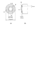
- FIG. 5 is a schematic view showing a state of an end face on the side connected to a plug ferrule of a fiber stub showing a fourth embodiment of the present invention. Since the end surface 5 of the fiber stub 4 is provided with a plurality of circumferentially recessed portions, the foreign matter moves from the outer periphery of the fiber stub 4 to the center in the process of repeatedly inserting and removing the plug ferrule into the optical receptacle 1. Can be stored more reliably.
- the width, depth, and cross-sectional shape of the first concave portion 81 on the inner peripheral side and the second concave portion 82 on the outer peripheral side need not be the same.
- FIG. 6 is a schematic cross-sectional view of an optical receptacle showing a fifth embodiment of the present invention.
- FIG. 6A is a schematic cross-sectional view showing an optical receptacle according to the present embodiment.
- FIG.6 (b) is a schematic cross section showing the end surface of the fiber stub of this embodiment.
- the members provided in the optical receptacle 1a shown in FIG. 6A are the same as those in the first embodiment.
- the central portion 5a of the end face 5 of the fiber stub 4 on the side connected to the plug ferrule is polished into a convex spherical shape.
- the radius of curvature of the convex spherical surface is R7 to R25.
- an outer portion (foreign matter movement suppressing portion: first portion) 11 is provided outside the central portion 5a polished into a convex spherical shape.
- the surface roughness of the outer portion 11 is made larger than the surface roughness of the central portion 5a so as to suppress the movement of foreign matter moving from the outer peripheral side toward the central portion 5a. Note that the plug ferrule inserted into the optical receptacle is omitted as appropriate.
- the average height Rc of the outer portion 11 is 0.305 or more. More desirably, the average height Rc of the outer portion 11 is not less than 0.305 and not more than 0.606.
- the skewness (distortion degree) Rsk of the outer portion 11 is ⁇ 0.2 or less. More preferably, the skewness Rsk of the outer portion 11 is ⁇ 0.3 or less.
- the average height Rc and the skewness Rsk are calculated based on JIS B 0601-2001. Details of more specific measuring methods of the average height Rc and the skewness Rsk will be described later.
- the central portion 5a of the end surface 5 of the fiber stub 4 on the side connected to the plug ferrule is polished into a convex spherical shape.
- an outer portion 11 is provided outside the central portion 5 a polished into a convex spherical shape.
- the surface roughness of the outer portion 11 is made larger than the surface roughness of the central portion 5a so as to suppress the movement of foreign matter moving from the outer peripheral side toward the central portion 5a.
- the outer portion 11 is formed outside the region 9 (see FIG. 3 or FIG. 5) where the plug ferrule and the fiber stub 4 may come into contact when the plug ferrule is inserted into the optical receptacle 1a. Accordingly, when the plug ferrule is repeatedly inserted into and removed from the optical receptacle 1a, foreign matter on the outer peripheral portion of the fiber stub 4 is prevented from moving to the region 9 connected to the plug ferrule on the end surface 5 of the fiber stub 4. The plug ferrule and the fiber stub 4 are securely connected.
- the region 9 in which the plug ferrule and the fiber stub 4 may come into contact is a region within ⁇ 250 micrometers from the center of the fiber stub 4 (FIG. 6B). Area of the outer diameter D1 shown in FIG. For this reason, in the present embodiment, the outer diameter of the end surface 5 necessary for reliably connecting the convex spherical end surface 5 to the plug ferrule needs to be 250 micrometers or more.
- the surface roughness of the central portion 5a polished into a convex spherical shape is generally an arithmetic average roughness (Ra) of 0.1 micrometers or less.
- the surface roughness of the outer portion 11 is desirably about arithmetic average roughness (Ra) of about 3.2 micrometers or less in order to reliably hold foreign matter and to produce economically.
- Ra arithmetic average roughness
- the outer portion 11 is formed by machining, a large stress is applied to the ferrule 3 with the end of the minute unevenness on the outer portion 11 as a base point. 3 cracks and cracks may occur.
- the surface roughness of the outer portion 11 can be measured by, for example, a laser microscope.
- a method for forming minute irregularities on the outer portion 11 a method of forming by processing with a rough grindstone or a method of roughening the surface by sandblast after forming a taper can be considered.
- FIG. 7 is a schematic cross-sectional view of an optical receptacle showing a sixth embodiment of the present invention.
- FIG. 7A is a schematic cross-sectional view showing an optical receptacle according to the present embodiment.
- FIG.7 (b) is a schematic cross section showing the end surface of the fiber stub of this embodiment.
- the members included in the optical receptacle 1b shown in FIG. 7A are the same as those in the first embodiment.
- the center portion 5a of the end face of the fiber stub on the side connected to the plug ferrule is polished into a convex spherical shape, and the end face of the fiber stub is formed on the outer peripheral portion of the fiber stub from the central portion 5a polished into the convex spherical shape.
- the taper portion 13 has a continuous taper portion (foreign matter movement suppression portion: first portion) 13, and the surface roughness of the taper portion 13 is such that the movement of the foreign matter moving from the outer peripheral portion side toward the central portion 5a is suppressed. It is made larger than the surface roughness of the part 5a. Note that the plug ferrule inserted into the optical receptacle is omitted as appropriate.
- the average height Rc of the tapered portion 13 is 0.305 or more. More desirably, the average height Rc of the tapered portion 13 is 0.305 or more and 0.606 or less.
- the skewness (distortion degree) Rsk of the tapered portion 13 is ⁇ 0.2 or less. More preferably, the skewness Rsk of the tapered portion 13 is ⁇ 0.3 or less.
- the average height Rc and the skewness Rsk are calculated based on JIS B 0601-2001. Details of more specific measuring methods of the average height Rc and the skewness Rsk will be described later.
- the end face 5 of the fiber stub 4 on the side connected to the plug ferrule is polished into a convex spherical shape, and the end face of the fiber stub 4 is convex spherical.
- the tapered portion 13 is connected to the outer peripheral portion of the fiber stub 4 from the polished central portion 5a, and the surface roughness of the tapered portion 13 suppresses the movement of foreign matters moving from the outer peripheral portion side toward the central portion.
- the end face 5 of the fiber stub 4 is equivalent to the central portion 5a.
- the length of the sleeve 7 holding the fiber stub 4 is sufficiently secured, so that the Wiggle loss can be suppressed.
- FIG. 7B is an enlarged schematic cross-sectional view of the tip of the fiber stub in the sixth embodiment of the present invention.
- the outer diameter D2 of the end face 5 necessary for the convex spherical end face 5 to be securely connected to the plug ferrule is 250 micrometers or more.
- the surface roughness of the end surface 5 polished into a convex spherical shape is generally an arithmetic roughness average (Ra) of 0.1 micrometers or less.
- the plug ferrule when the plug ferrule is repeatedly inserted into and removed from the optical receptacle 1b in the tapered portion 13 in which the surface roughness is made larger than the roughness of the end surface 5 by reducing the end surface 5, it moves from the outer peripheral side to the central portion 5a.
- the effect which suppresses the movement of the foreign material to do can be enlarged. Therefore, it is desirable that the outer diameter D2 of the end face 5 is 250 micrometers or more and less than or equal to one half of the outer diameter of the ferrule 3.
- the surface roughness of the tapered flat surface 13 is desirably about arithmetic average roughness (Ra) of about 3.2 micrometers in order to reliably retain foreign matters and to produce economically.
- Ra arithmetic average roughness
- the arithmetic roughness average is 3.2 micrometers or more
- the tapered flat surface 13 is formed by machining, a large stress is applied to the ferrule 3 based on the end of the minute irregularities on the tapered flat surface 13. And the ferrule 3 may be cracked or chipped.
- the surface roughness of the tapered flat surface 13 can be measured by, for example, a laser microscope.
- a method for forming minute irregularities on the tapered flat surface 13 a method of forming by processing with a rough grindstone, a method of roughening the surface by sandblasting after forming the taper, etc. are conceivable. .
- the length L1 from the convex spherical end face 5 connected to the plug ferrule of the ferrule 3 to the portion where the tapered flat surface 13 is connected to the cylindrical surface is the length that the sleeve 7 holds the fiber stub 4. It is desirable that the thickness is 0.2 mm or less in order to increase the wiggle loss and to further reduce the decrease in the wiggle loss.
- FIG. 8 is a schematic cross-sectional view of an optical receptacle showing a seventh embodiment of the present invention.
- FIG. 8A is a schematic cross-sectional view showing the optical receptacle according to the present embodiment.
- FIG. 8B is a schematic cross-sectional view showing the end face of the fiber stub of the present embodiment.
- the end face 5 of the fiber stub 4 is equivalent to the central portion 5a.
- the surface roughness of the taper part 15 is made larger than the surface roughness of the projection part 5b.
- the average height Rc of the tapered portion 15 is 0.305 or more. More desirably, the average height Rc of the tapered portion 15 is not less than 0.305 and not more than 0.606.
- the skewness (degree of distortion) Rsk of the tapered portion 15 is ⁇ 0.2 or less. More preferably, the skewness Rsk of the tapered portion 15 is ⁇ 0.3 or less.
- the average height Rc and the skewness Rsk are calculated based on JIS B 0601-2001. Details of more specific measuring methods of the average height Rc and the skewness Rsk will be described later.
- the length L2 is preferably 0.2 mm or less in order to increase the length that the sleeve 7 holds the fiber stub 4 and to further reduce the decrease in the Wiggle loss.
- the tapered flat surface 15 is a surface that is perpendicular to the central axis C1 of the fiber stub 4 as in the prior art document 3, the same effect can be obtained.
- the end surface 5 of the fiber stub 4 is cleaned before the plug ferrule is inserted, the foreign matter can be easily moved to the outside and the ferrule 3 is press-fitted into the holder 6 by using the tapered flat surface.
- FIG. 9 is a schematic cross-sectional view showing a state in which a plurality of plug ferrules are connected to each other via a sleeve.
- a plurality of optical fiber connectors may be connected to each other via an adapter or a sleeve without using an optical receptacle as described above with reference to FIGS.
- the first plug ferrule 20 a in the first optical fiber connector is connected to the second plug ferrule (other member) 20 b in the second optical fiber connector via the sleeve 30.
- the first plug ferrule 20a is different from the second plug ferrule 20b.
- the structure of the first plug ferrule 20a is the same as the structure of the second plug ferrule 20b.
- the first plug ferrule 20a will be described as an example.
- the first plug ferrule 20 a has an optical fiber 2, a ferrule 3, and a flange 21.
- the optical fiber 2 conducts light.
- the ferrule 3 contains the optical fiber 2.
- the flange 21 is provided at the end of the ferrule 3 and includes at least a part of the ferrule 3.
- the end face 5 on the side where a plurality of ferrules 3 are connected is provided with a foreign substance movement suppressing part that suppresses foreign substances that move from the outer peripheral part of the ferrule 3 toward the center part by inserting and removing the plug ferrule.
- the first plug ferrule 20a and the second plug ferrule are provided on the end face 5 of the ferrule 3 of the first plug ferrule 20a and on the end face 5 connected to the second plug ferrule 20b.
- a foreign substance movement suppression unit is provided that suppresses foreign substances that move from the outer peripheral part of the ferrule 3 toward the central part by inserting or removing at least one of 20b.
- a foreign substance movement suppressing portion is provided on the end face 5 of the ferrule 3 of the second plug ferrule 20b and on the end face 5 on the side connected to the first plug ferrule 20a.
- the end face 5 of the ferrule 3 of the first plug ferrule 20a is polished to a convex spherical surface.
- the ferrule 3 of the first plug ferrule 20a has the end surface 5 polished in a convex spherical shape on the side connected to the second plug ferrule 20b.
- the radius of curvature R of the end face 5 is, for example, about R7 to R25.
- the end surface 5 of the ferrule 3 is provided with a circumferentially recessed portion 8 for accommodating a foreign substance moving from the outer periphery of the ferrule 3 toward the center.
- the cross-sectional view of the recess 8 has a square shape, a V shape, a semicircle, or various shapes that become narrower toward the bottom surface.
- the circumferentially continuous recesses 8 are regions 9 that may come into contact with the second plug ferrule 20 b when the first plug ferrule 20 a is inserted into the sleeve 30. (See FIG. 3).
- the surface roughness of the inner surface of the recess 8 is larger than the surface roughness of the region other than the recess 8 on the end surface 5 of the ferrule 3.
- the surface roughness of the inner surface of the recess 8 is as described above with reference to FIG.
- the end surface 5 of the ferrule 3 is provided with a plurality of circumferential recesses (for example, the first recess 81 and the second recess 82 illustrated in FIG. 5).
- the end surface 5 of the ferrule 3 has an outer side outside the central portion 5 a (see FIG. 6B) polished into a convex spherical shape. Part 11 is provided. The surface roughness of the outer portion 11 is made larger than the surface roughness of the central portion 5a so as to suppress the movement of foreign matter moving from the outer peripheral side toward the central portion 5a.
- the end surface 5 of the ferrule 3 has an outer periphery of the ferrule 3 from the central portion 5a (see FIG. 7B) polished into a convex spherical shape.
- the taper part 13 which continues to a part is provided.
- the surface roughness of the taper part 13 is made larger than the surface roughness of the center part 5a so that the movement of the foreign material which moves to the center part 5a from the outer peripheral part side may be suppressed.
- the protruding portion 5 b including the end surface 5 of the ferrule 3 protrudes from the tapered portion 15. More specifically, the protrusion 5b including the end face 5 of the ferrule 3 of the first plug ferrule 20a is different from the ferrule 3 of the second plug ferrule 20b when the ferrule 3 of the first plug ferrule 20a is viewed from the tapered portion 15. It protrudes to the connecting side.
- the shape and material of the ferrule 3 and the shape and roughness of the end face 5 of the ferrule 3 are as described above with reference to FIGS. 1 to 8B.
- the foreign matter on the outer periphery of the ferrule 3 becomes the center of the end surface 5 of the ferrule 3. It is possible to prevent a loss from occurring by moving to.
- FIG. 10 is a table illustrating an example of the result of the study on the surface roughness performed by the inventor.
- FIG. 10A is a table illustrating the arithmetic average roughness Ra, average height Rc, and skewness Rsk on the processed surface (rough surface).
- FIG. 10B is a table illustrating the arithmetic average roughness Ra, average height Rc, and skewness Rsk on the unprocessed surface.
- FIG. 10C is a table illustrating the arithmetic average roughness Ra, average height Rc, and skewness Rsk on the polished surface.
- FIG. 10D is a table illustrating the average values of the arithmetic average roughness Ra, the average height Rc, and the skewness Rsk on each of the processed surface, the unprocessed surface, and the polished surface.
- the “processed surface (rough surface)” refers to a surface rougher than the surface of the central portion 5a polished into a convex spherical shape.
- the processed surface is the surface of the outer portion 11.
- the processed surface is the surface of the tapered portion 13.
- Unprocessed surface refers to a surface that has not been subjected to surface processing or surface treatment.
- Polyished surface refers to a polished surface.
- the polishing surface is the surface of the convex spherical central portion 5a.
- the polishing surface is the end surface 5 (equivalent to the central portion 5a in the example of FIG. 7).
- FIG. 10A five samples were measured on the processed surface.
- FIG. 10B five samples were measured for the unprocessed surface. For the polished surface, two samples were measured.
- the arithmetic average roughness Ra, average height Rc, and skewness Rsk are calculated based on JIS B 0601-2001.
- the roughness curve of the end face of the ferrule 3 was measured under the following conditions.
- Measuring instrument Laser microscope (Olympus, OLS4000) Measurement magnification: 50 times Cut-off (phase compensation type high-pass filter) ⁇ c: 25 ⁇ m
- the arithmetic average roughness Ra is obtained by the following equation (1)
- the average height Rc is obtained by the following equation (2)
- the skewness Rsk is obtained by the following equation (3).
- Equation (2) m is the number of contour curve elements, and Zti is the average value of the heights of the contour curve elements.
- Zq is a root mean square height, and Zn is a height value in the roughness curve.
- Skewness Rsk represents the symmetry between the concavo-convex peaks (convex) and valleys (concave). If the uneven shape is a sine distribution, the skewness Rsk is zero. The skewness Rsk is negative when the area of the peak (convex) is larger than the area of the valley (concave) when viewed in the direction perpendicular to the end face of the ferrule 3 (the sharpness of the convex part is smaller than the sharpness of the concave part) ).
- the arithmetic average roughness Ra of the processed surface is 0.130 or more and 0.192 or less.
- the average value of the arithmetic average roughness Ra of the processed surface is 0.166.
- the average height Rc of the processed surface is 0.305 or more and 0.606 or less.
- the average value of the average height Rc of the processed surface is 0.489.
- the skewness Rsk of the processed surface is ⁇ 0.355 or more and ⁇ 0.198 or less.
- the average value of the skewness Rsk of the processed surface is ⁇ 0.268.
- the foreign matter countermeasure effect on the processed surface is OK ( ⁇ ) for all samples.
- the plug ferrule was repeatedly inserted into and removed from the optical receptacle, and adhesion of foreign matter on the polished surface was confirmed every five insertions / removals.
- the foreign matter countermeasure effect was set to “OK ( ⁇ )”.
- the foreign matter countermeasure effect is “NG ( ⁇ )”.
- the arithmetic average roughness Ra of the unprocessed surface is 0.020 or more and 0.201 or less.
- the average value of the arithmetic average roughness Ra of the unprocessed surface is 0.124.
- the average height Rc of the unprocessed surface is 0.047 or more and 0.072 or less.
- the average value of the average height Rc of the unprocessed surface is 0.061.
- the skewness Rsk of the unprocessed surface is ⁇ 0.182 or more and 0.183 or less.
- the average value of the skewness Rsk of the unprocessed surface is ⁇ 0.021.
- the foreign matter countermeasure effect on the unprocessed surface is NG ( ⁇ ) for all samples.
- the arithmetic average roughness Ra of the polished surface is 0.002 or more and 0.004 or less.
- the average value of the arithmetic average roughness Ra of the polished surface is 0.003.
- the average height Rc of the polished surface is 0.008 or more and 0.009 or less.
- the average value of the average height Rc of the polished surface is 0.0085.
- the skewness Rsk of the polished surface is 0.532 or more and 0.954 or less.
- the average value of the skewness Rsk of the polished surface is 0.743.
- the average height Rc when the average height Rc is relatively large, the height of the peaks and valleys existing on the surface is large, and foreign substances are easily caught on the peaks or valleys. For this reason, when the average height Rc is relatively large, it is possible to prevent foreign matters from moving to the central portion 5a.
- the skewness Rsk When the skewness Rsk is relatively small, the plane becomes rich in a mountain (a state in which a valley having a relatively small width exists between the peaks having a relatively large width), and the contact area between the foreign matter and the surface Is relatively wide. For this reason, when the skewness Rsk is relatively small, it is possible to prevent foreign matters from moving to the central portion 5a.
- FIG. 11 is a graph illustrating another example of the result of the study on surface roughness performed by the present inventor.
- the inventor has studied surface roughness using an optical receptacle provided with a ferrule 3 having a processed surface and an optical receptacle provided with a ferrule 3 having an unprocessed surface.
- the “processed surface” in this study is a surface that has been subjected to surface processing using a diamond grindstone after the formation of the ferrule 3.
- the “unprocessed surface” in this study is a surface that remains as it is after the ferrule 3 is formed.
- the examination method is as follows. First, both the optical receptacle and the plug ferrule are sufficiently cleaned, and the plug ferrule is repeatedly inserted into and removed from the optical receptacle. Subsequently, the adhesion of foreign matter on the polished surface is confirmed every 5 insertions / removals, and the insertion / extraction of the plug ferrule to / from the optical receptacle is repeated 30 times. However, plugging and unplugging of the plug ferrule is interrupted when it is confirmed that foreign matter has adhered to the polished surface. For the optical receptacle provided with the ferrule 3 having a processed surface, five samples were measured. For the optical receptacle provided with ferrule 3 having an unprocessed surface, five samples were measured. The number of samples conforms to the “Telcordia standard”.
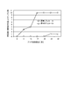
- FIG. 11 An example of the examination results is as shown in FIG.
- the horizontal axis of the graph shown in FIG. 11 represents the number of plug ferrule insertions / removals when the adhesion of foreign matter is confirmed on the polished surface.
- the vertical axis of the graph shown in FIG. 11 represents the number of samples (accumulated number) in which foreign matter has adhered to the polished surface.
- the number of samples in which foreign matter adhered to the polished surface when the insertion and removal of the plug ferrule was repeated 25 times was “3”.
- the optical receptacle including the ferrule 3 having an unprocessed surface the number of samples in which foreign matter adhered to the polished surface when the plug ferrule insertion / extraction was repeated 10 times was “7”.
- the foreign matter countermeasure effect is “OK ( ⁇ )”. " On the other hand, when the number of samples with foreign matter adhering to the polished surface was 4 or more, the foreign matter countermeasure effect was “NG ( ⁇ )”. “25 times” conforms to the “Telcordia standard”. According to this, the foreign matter countermeasure effect of the optical receptacle provided with the ferrule 3 having the processed surface is OK ( ⁇ ). On the other hand, the foreign matter countermeasure effect of the optical receptacle provided with the ferrule 3 having an unprocessed surface is NG ( ⁇ ).
- FIG. 12 is a schematic diagram showing a sample used for the study on the recess (groove) performed by the present inventor.
- FIG. 13 is a graph illustrating an example of a result of a study on a recess (groove) performed by the present inventor.
- FIG. 12A is a schematic plan view showing a sample used for the study on the concave portion (groove portion).
- FIG. 12B is a schematic cross-sectional view taken along the section AA shown in FIG.
- the present inventor has studied the recess using the optical receptacle provided with the ferrule 3 having the recess 8 (see FIG. 1) and the optical receptacle provided with the ferrule 3 not having the recess 8.
- the ferrule 3 that does not have the recess 8 is a ferrule that remains in the state after molding.
- the ferrule 3 having the recess 8 is as shown in FIGS. 12 (a) and 12 (b).
- the concave portion 8 was formed by processing using a grindstone.
- the examination method is the same as the examination method described above with reference to FIG.
- An example of the examination result is as shown in FIG.
- the horizontal axis of the graph shown in FIG. 13 is the same as the horizontal axis of the graph shown in FIG.
- the vertical axis of the graph shown in FIG. 13 is the same as the vertical axis of the graph shown in FIG.
- the number of samples in which foreign matter adhered to the polished surface when the plug ferrule insertion / extraction was repeated 25 times was “1”.
- the optical receptacle including the ferrule 3 that does not have the concave portion 8 the number of samples in which foreign matter adhered to the polished surface when the plug ferrule insertion / extraction was repeated five times was “3”.
- the evaluation method of the foreign matter countermeasure effect is the same as the evaluation method described above with reference to FIG. According to this, the foreign matter countermeasure effect of the optical receptacle provided with the ferrule 3 having the concave portion 8 is OK ( ⁇ ). On the other hand, the foreign matter countermeasure effect of the optical receptacle provided with the ferrule 3 that does not have the recess 8 is NG ( ⁇ ).
- FIG. 14 is a table illustrating an example of a result of a study on the surface roughness of the inner surface of the recess (groove) performed by the present inventor.
- the inventor has studied the surface roughness of the inner surface of the recess 8 shown in FIG. 4, for example. More specifically, the inventor has an arithmetic average roughness of the inner surface of the recess 8 of 0.2, 0.4, 0.8, 1.6, 3.2, 4.8, 6.4 micrometers. In each case, the workability of the inner surface of the recess 8 was examined.
- the productivity of the ferrule 3 is relatively high. Moreover, it can suppress that a crack etc. generate
- the arithmetic average roughness of the inner surface of the concave portion 8 is 4.8 and 6.4 micrometers
- the surface is relatively rough, and therefore cracks may occur when the concave portion 8 is processed. Therefore, the workability when the arithmetic average roughness of the inner surface of the recess 8 is 4.8 and 6.4 micrometers is NG ( ⁇ ).
- the arithmetic average roughness (Ra) of the inner surface of the concave portion 8 is not less than 0.8 micrometers and not more than 3.2 micrometers.
- the plug ferrule when the plug ferrule is repeatedly inserted and removed from the optical receptacle, the foreign matter on the outer periphery of the fiber stub is prevented from moving to the center of the fiber stub end surface, and the sleeve is made of fiber.
- An optical receptacle capable of reducing the Wiggle loss by maintaining the length for holding the stub is provided.
Landscapes
- Physics & Mathematics (AREA)
- General Physics & Mathematics (AREA)
- Optics & Photonics (AREA)
- Mechanical Coupling Of Light Guides (AREA)
- Optical Couplings Of Light Guides (AREA)
Abstract
Description
他の部材と接続する側の凸球面状に研磨された端面に、挿抜により外周部から、前記端面の中心部に向けて移動する異物の移動を抑制する異物移動抑制部を有することを特徴とするフェルールである。
光レセプタクル1は、光を導通するための光ファイバ2を内包するフェルール3を有するファイバスタブ4と、ファイバスタブ4を保持するための保持具6と、ファイバスタブ4の先端を一端で保持し、他端で光レセプタクル1に挿入されるプラグフェルール(他の部材)を保持可能なスリーブ7と、を備える。フェルール3のプラグフェルールと接続する側の端面5に、プラグフェルールの挿抜によりフェルール3の外周部から中心部に向けて移動する異物を収容するための円周状に連なる凹部(異物移動抑制部)8が設けられている。なお、光レセプタクル1に挿入されるプラグフェルールは適宜省略する。
凹部8は一定以上の幅および深さを持っていれば異物を収容することは可能となる。しかしファイバスタブ4の端面5に凹部8を効率的、且つ経済的に設けるためには、図2(a)~図2(d)のように凹部8の断面図が四角形、V形状、半円、または底面に行くに従って幅が細くなる各種形状をしていることが望ましい。
凹部8の内面の面粗さを、フェルール3の端面5の凹部8以外の領域の面粗さよりも大きくすることにより、光レセプタクル1にプラグフェルールを繰返し挿抜する過程で凹部8に落下した異物の全体または一部が、凹部8の内面に形成された微小な凹凸8aに嵌まりこみアンカー効果を果たすことで、より確実に異物を凹部8内に収容することが可能となる。
ファイバスタブ4の端面5に、複数の円周状に連なる凹部が設けられていることにより、光レセプタクル1にプラグフェルールを繰返し挿抜する過程で、ファイバスタブ4の外周部から中心部に移動する異物をより確実に収納することができる。内周側にある第1の凹部81と、外周側にある第2の凹部82の幅、深さ、および断面形状は同じである必要はない。
図6(a)は、本実施形態にかかる光レセプタクルを表す模式断面図である。図6(b)は、本実施形態のファイバスタブの端面を表す模式断面図である。
外側部11のスキューネス(歪み度)Rskは、-0.2以下である。より望ましくは、外側部11のスキューネスRskは、-0.3以下である。
平均高さRc及びスキューネスRskは、JIS B 0601-2001に基づき算出される。平均高さRc及びスキューネスRskのより具体的な測定方法の詳細については、後述する。
なお、各部材の材料等、および光レセプタクル1aの他の構造は、図1に関して前述した通りである。
図7(a)は、本実施形態にかかる光レセプタクルを表す模式断面図である。図7(b)は、本実施形態のファイバスタブの端面を表す模式断面図である。
テーパー部13のスキューネス(歪み度)Rskは、-0.2以下である。より望ましくは、テーパー部13のスキューネスRskは、-0.3以下である。
平均高さRc及びスキューネスRskは、JIS B 0601-2001に基づき算出される。平均高さRc及びスキューネスRskのより具体的な測定方法の詳細については、後述する。
図8(a)は、本実施形態にかかる光レセプタクルを表す模式断面図である。図8(b)は、本実施形態のファイバスタブの端面を表す模式断面図である。
テーパー部15の平均高さRcは、0.305以上である。より望ましくは、テーパー部15の平均高さRcは、0.305以上、0.606以下である。
テーパー部15のスキューネス(歪み度)Rskは、-0.2以下である。より望ましくは、テーパー部15のスキューネスRskは、-0.3以下である。
平均高さRc及びスキューネスRskは、JIS B 0601-2001に基づき算出される。平均高さRc及びスキューネスRskのより具体的な測定方法の詳細については、後述する。
図9は、スリーブを介して複数のプラグフェルールが互いに接続された状態を表す模式的断面図である。
例えば、図2(a)~図2(d)に関して前述したように、凹部8の断面図は、四角形、V形状、半円、または底面に行くに従って幅が細くなる各種形状をしている。
例えば、図4に関して前述したように、凹部8の内面の面粗さは、フェルール3の端面5の凹部8以外の領域の面粗さよりも大きい。凹部8の内面の面粗さは、図4に関して前述した通りである。
例えば、図6(a)および図6(b)に関して前述したように、フェルール3の端面5において、凸球面状に研磨された中央部5a(図6(b)参照)の外側には、外側部11が設けられている。外側部11の面粗さは、外周部側から中央部5aに向けて移動する異物の移動を抑制するように、中央部5aの面粗さよりも大きくされている。
「未加工面」とは、表面加工あるいは表面処理を施していない面をいう。
「研磨面」とは、研磨された面をいう。図6に関して前述した光レセプタクル1aでは、研磨面は、凸球面状の中央部5aの表面である。図7に関して前述した光レセプタクル1bでは、研磨面は、端面5(図7の例では中央部5aと同等)である。
本実施形態では、フェルール3の端面の粗さ曲線を以下の条件で測定した。
測定機器:レーザ顕微鏡(オリンパス社製、OLS4000)
測定倍率:50倍
カットオフ(位相補償形高域フィルタ)λc:25μm
上記の条件によって測定した粗さ曲線から、算術平均粗さRaを以下の(1)式によって求め、平均高さRcを以下の(2)式によって求め、スキューネスRskを以下の(3)式によって求める。



(3)式において、Zqは二乗平均平方根高さ、Znは粗さ曲線における高さの値である。
「異物対策効果」については、光レセプタクルへのプラグフェルールの挿抜を繰り返し行い、挿抜5回毎に研磨面における異物の付着を確認した。光レセプタクルへのプラグフェルールの挿抜を25回繰り返した場合に、研磨面に付着した異物が3個以下であるときに、異物対策効果を「OK(○)」とした。一方で、研磨面に付着した異物が4個以上であるときに、異物対策効果を「NG(×)」とした。
また、スキューネスRskが相対的に小さいと、平面が山リッチ(幅が相対的に大きい山と山との間に幅が相対的に小さい谷が存在する状態)となり、異物と面との接触面積が相対的に広い。そのため、スキューネスRskが相対的に小さいと、異物が中央部5aに移動することを妨げることができる。
本発明者は、加工面を有するフェルール3を備えた光レセプタクルと、未加工面を有すフェルール3を備えた光レセプタクルと、を用いて面粗さに関する検討を行った。本検討の「加工面」は、フェルール3の成形後に、ダイヤモンド砥石を用いて表面加工を行った面である。本検討の「未加工面」は、フェルール3の成形後に形成された状態のままの面である。
これによれば、加工面を有するフェルール3を備えた光レセプタクルの異物対策効果は、OK(○)である。一方で、未加工面を有するフェルール3を備えた光レセプタクルの異物対策効果は、NG(×)である。
図13は、本発明者が実施した凹部(溝部)に関する検討の結果の一例を例示するグラフ図である。
図12(a)は、凹部(溝部)に関する検討に用いた試料を表す模式平面図である。図12(b)は、図12(a)に表した切断面A-Aにおける模式的断面図である。
検討結果の一例は、図13に表した通りである。図13に表したグラフ図の横軸は、図11に表したグラフ図の横軸と同じである。図13に表したグラフ図の縦軸は、図11に表したグラフ図の縦軸と同じである。図13に表したように、凹部8を有するフェルール3を備えた光レセプタクルでは、プラグフェルールの挿抜を25回繰り返した時点で研磨面に異物が付着した試料数は、「1」であった。一方で、凹部8を有していないフェルール3を備えた光レセプタクルでは、プラグフェルールの挿抜を5回繰り返した時点で研磨面に異物が付着した試料数は、「3」であった。
これによれば、凹部8を有するフェルール3を備えた光レセプタクルの異物対策効果は、OK(○)である。一方で、凹部8を有していないフェルール3を備えた光レセプタクルの異物対策効果は、NG(×)である。
本発明者は、例えば図4に表した凹部8の内面の面粗さについて検討を行った。より具体的には、本発明者は、凹部8の内面の算術平均粗さが0.2、0.4、0.8、1.6、3.2、4.8、6.4マイクロメートルのそれぞれの場合における凹部8の内面の加工性について検討を行った。
また、前述した各実施の形態が備える各要素は、技術的に可能な限りにおいて組み合わせることができ、これらを組み合わせたものも本発明の特徴を含む限り本発明の範囲に包含される。
2 光ファイバ
3 フェルール
4 ファイバスタブ
5 端面
5a 中央部
6 保持具
7 スリーブ
8 凹部
8a 凹凸
9 領域
11 外側部
13、15 テーパー部
81 第1の凹部
82 第2の凹部
Claims (18)
- 光を導通するための光ファイバを内包するフェルールを有するファイバスタブと、
前記ファイバスタブを保持するための保持具と、
前記ファイバスタブの先端を一端で保持し、他端で光レセプタクルに挿入されるプラグフェルールを保持可能なスリーブと、
を備え、
前記フェルールは、前記フェルールの前記プラグフェルールと接続する側の凸球面状に研磨された端面に、前記プラグフェルールの挿抜により前記フェルールの外周部から、前記端面の中心部に向けて移動する異物の移動を抑制する異物移動抑制部を有することを特徴とする光レセプタクル。 - 前記異物移動抑制部は、前記端面に設けられ円周状に連なる凹部を有することを特徴とする請求項1記載の光レセプタクル。
- 前記凹部が、前記プラグフェルールが挿入された際に前記フェルールと前記プラグフェルールが接触する部分よりも外側にあることを特徴とする請求項2記載の光レセプタクル。
- 前記凹部が、複数設けられていることを特徴とする請求項2記載の光レセプタクル。
- 前記凹部の内面の面粗さが、前記凹部以外の領域の面粗さよりも大きいことを特徴とする請求項2記載の光レセプタクル。
- 前記異物移動抑制部は、前記フェルールの前記プラグフェルールと接続する側の端面のうち前記プラグフェルールと直接的には接触しない第1の部分を有し、
前記第1の部分の面の平均高さは、0.305以上であり、前記第1の部分の面のスキューネスは、-0.2以下であることを特徴とする請求項1記載の光レセプタクル。 - 前記第1の部分のうちの少なくとも一部は、前記ファイバスタブの外周部に連なるテーパー状を有することを特徴とする請求項6記載の光レセプタクル。
- 前記フェルールの前記プラグフェルールと接続する側の端面のうち前記プラグフェルールと直接的に接触する第2の部分は、前記第1の部分よりも前記フェルールが前記プラグフェルールと接続する側に突出したことを特徴とする請求項6記載の光レセプタクル。
- 前記第2の部分の端面と、前記第2の部分が前記第1の部分と接続される部分と、の間の距離は、0.2ミリメートル以下であることを特徴とする請求項8記載の光レセプタクル。
- 光を導通するための光ファイバを内包するフェルールであって、
他の部材と接続する側の凸球面状に研磨された端面に、挿抜により外周部から、前記端面の中心部に向けて移動する異物の移動を抑制する異物移動抑制部を有することを特徴とするフェルール。 - 前記異物移動抑制部は、前記端面に設けられ円周状に連なる凹部を有することを特徴とする請求項10記載のフェルール。
- 前記凹部は、前記他の部材と接触する部分よりも外側にあることを特徴とする請求項11記載のフェルール。
- 前記凹部が、複数設けられていることを特徴とする請求項11記載のフェルール。
- 前記凹部の内面の面粗さが、前記凹部以外の領域の面粗さよりも大きいことを特徴とする請求項11記載のフェルール。
- 前記異物移動抑制部は、前記端面のうち前記他の部材と直接的には接触しない第1の部分を有し、
前記第1の部分の面の平均高さは、0.305以上であり、前記第1の部分の面のスキューネスは、-0.2以下であることを特徴とする請求項10記載のフェルール。 - 前記第1の部分のうちの少なくとも一部は、前記他の部材の外周部に連なるテーパー状を有することを特徴とする請求項15記載のフェルール。
- 前記端面のうち前記他の部材と直接的に接触する第2の部分は、前記第1の部分よりも前記他の部材と接続する側に突出したことを特徴とする請求項15記載のフェルール。
- 光を導通するための光ファイバを内包するフェルールであって、他の部材と接続する側の凸球面状に研磨された端面に、挿抜により外周部から、前記端面の中心部に向けて移動する異物の移動を抑制する異物移動抑制部を有するフェルールと、
前記フェルールのうちの少なくとも一部を内包するフランジと、
を備えたことを特徴とするプラグフェルール。
Priority Applications (4)
| Application Number | Priority Date | Filing Date | Title |
|---|---|---|---|
| US14/900,376 US9810853B2 (en) | 2013-06-28 | 2014-06-27 | Optical receptacle, ferrule, and plug ferrule |
| CN201480035647.6A CN105324695B (zh) | 2013-06-28 | 2014-06-27 | 光插座、套管及插头套管 |
| US15/188,294 US10048448B2 (en) | 2013-06-28 | 2016-06-21 | Optical receptacle, ferrule, and plug ferrule |
| US15/723,394 US10409008B2 (en) | 2013-06-28 | 2017-10-03 | Optical receptacle, ferrule, and plug ferrule |
Applications Claiming Priority (8)
| Application Number | Priority Date | Filing Date | Title |
|---|---|---|---|
| JP2013136497 | 2013-06-28 | ||
| JP2013-136498 | 2013-06-28 | ||
| JP2013136498 | 2013-06-28 | ||
| JP2013-136497 | 2013-06-28 | ||
| JP2014-045650 | 2014-03-07 | ||
| JP2014045650 | 2014-03-07 | ||
| JP2014-095241 | 2014-05-02 | ||
| JP2014095241A JP5656099B1 (ja) | 2013-06-28 | 2014-05-02 | 光レセプタクル、フェルールおよびプラグフェルール |
Related Child Applications (3)
| Application Number | Title | Priority Date | Filing Date |
|---|---|---|---|
| US14/900,376 A-371-Of-International US9810853B2 (en) | 2013-06-28 | 2014-06-27 | Optical receptacle, ferrule, and plug ferrule |
| US15/188,294 Division US10048448B2 (en) | 2013-06-28 | 2016-06-21 | Optical receptacle, ferrule, and plug ferrule |
| US15/723,394 Continuation US10409008B2 (en) | 2013-06-28 | 2017-10-03 | Optical receptacle, ferrule, and plug ferrule |
Publications (1)
| Publication Number | Publication Date |
|---|---|
| WO2014208744A1 true WO2014208744A1 (ja) | 2014-12-31 |
Family
ID=52142067
Family Applications (1)
| Application Number | Title | Priority Date | Filing Date |
|---|---|---|---|
| PCT/JP2014/067227 Ceased WO2014208744A1 (ja) | 2013-06-28 | 2014-06-27 | 光レセプタクル、フェルールおよびプラグフェルール |
Country Status (4)
| Country | Link |
|---|---|
| US (3) | US9810853B2 (ja) |
| JP (1) | JP5656099B1 (ja) |
| CN (1) | CN105324695B (ja) |
| WO (1) | WO2014208744A1 (ja) |
Cited By (1)
| Publication number | Priority date | Publication date | Assignee | Title |
|---|---|---|---|---|
| CN116560027A (zh) * | 2023-07-04 | 2023-08-08 | 浙江浙能能源服务有限公司 | 一种虚拟电厂通信终端施工装置 |
Families Citing this family (4)
| Publication number | Priority date | Publication date | Assignee | Title |
|---|---|---|---|---|
| US10598866B2 (en) * | 2015-11-18 | 2020-03-24 | Lumasense Technologies Holdings, Inc. | Low reflection fiber-optic connector |
| EP3276386B1 (en) * | 2016-07-25 | 2025-05-14 | IMEC vzw | Optical coupling of embedded optical fibers |
| US10412293B2 (en) * | 2017-06-06 | 2019-09-10 | Foxconn Interconnect Technology Limited | Transmitter optical sub-assembly having improved receptacle |
| CN110632709A (zh) * | 2019-10-31 | 2019-12-31 | 四川天勤通科技有限公司 | 一种非接触式无损光纤跳线及制作方法 |
Citations (7)
| Publication number | Priority date | Publication date | Assignee | Title |
|---|---|---|---|---|
| JPH04273204A (ja) * | 1990-11-09 | 1992-09-29 | General Motors Corp <Gm> | 光ファイバ用端子 |
| WO2002029461A1 (en) * | 2000-09-29 | 2002-04-11 | Cielo Communications, Inc. | Apparatus and method for vcsel monitoring using scattering and reflection of emitted light |
| JP2004354672A (ja) * | 2003-05-29 | 2004-12-16 | Jst Mfg Co Ltd | 光リセプタクル |
| JP2005134550A (ja) * | 2003-10-29 | 2005-05-26 | Kyocera Corp | ファイバスタブおよびそれを用いた光レセプタクルとその製造方法およびそれを用いた光モジュール |
| JP2005522692A (ja) * | 2002-04-05 | 2005-07-28 | パワーザイム,インコーポレイテッド | 分析物センサー |
| JP2009151200A (ja) * | 2007-12-21 | 2009-07-09 | Toto Ltd | 光接続スリーブ、光レセプタクル、および光モジュール |
| JP2013088462A (ja) * | 2011-10-13 | 2013-05-13 | Auto Network Gijutsu Kenkyusho:Kk | フェルール対、雄型フェルール、雌型フェルール及び光コネクタ |
Family Cites Families (41)
| Publication number | Priority date | Publication date | Assignee | Title |
|---|---|---|---|---|
| US5537501A (en) | 1989-11-24 | 1996-07-16 | Nippon Telegraph And Telephone Corporation | Optical connector |
| US5673346A (en) | 1989-11-24 | 1997-09-30 | Nippon Telegraph And Telephone Corporation | Optical jack for plug-jack optical connector |
| EP0523473B1 (en) | 1991-07-05 | 1996-12-04 | Nippon Steel Welding Products & Engineering Co., Ltd. | Connector assembly with a metal tube clad optical fiber cable |
| US5325455A (en) | 1992-10-21 | 1994-06-28 | Minnesota Mining And Manufacturing Company | Fiber optic edge card connector |
| US5436995A (en) | 1993-05-14 | 1995-07-25 | Nippon Telegraph And Telephone Corporation | Optical fiber connector unit and optical fiber connector |
| US5925191A (en) * | 1996-05-13 | 1999-07-20 | Stein; Harold M. | Ferrule cleaning rod and method of use |
| JPH1039167A (ja) * | 1996-05-23 | 1998-02-13 | Pilot Precision Co Ltd | フェルール |
| JP3132998B2 (ja) * | 1996-07-09 | 2001-02-05 | セイコーインスツルメンツ株式会社 | 光コネクタ用フェルール |
| JP2985065B2 (ja) * | 1997-03-06 | 1999-11-29 | セイコーインスツルメンツ株式会社 | スリーブ |
| JP2001066468A (ja) | 1999-08-27 | 2001-03-16 | Hitachi Cable Ltd | 光レセプタクル |
| US6583902B1 (en) | 1999-12-09 | 2003-06-24 | Alvesta, Inc. | Modular fiber-optic transceiver |
| US6349918B1 (en) | 1999-12-27 | 2002-02-26 | Donald D. Bunker | Motor mount insert and method of forming same |
| JP4014776B2 (ja) | 2000-01-06 | 2007-11-28 | 株式会社フジクラ | 光コネクタ |
| US6607308B2 (en) | 2001-02-12 | 2003-08-19 | E20 Communications, Inc. | Fiber-optic modules with shielded housing/covers having mixed finger types |
| US6659655B2 (en) | 2001-02-12 | 2003-12-09 | E20 Communications, Inc. | Fiber-optic modules with housing/shielding |
| EP1249282A3 (en) * | 2001-04-11 | 2003-04-09 | NTT Advanced Technology Corporation | Cleaning tool for optical connector |
| JP2005091379A (ja) | 2001-10-09 | 2005-04-07 | Suncall Corp | 光ファイバ用コネクタ |
| JP2003207687A (ja) | 2002-01-16 | 2003-07-25 | Seiko Instruments Inc | フェルール及びその製造方法並びに光コネクタプラグ |
| US6746158B2 (en) | 2002-01-31 | 2004-06-08 | Agilent Technologies, Inc. | Pull detach mechanism for fiber optic transceiver module |
| US6841733B2 (en) | 2002-02-14 | 2005-01-11 | Finisar Corporation | Laser monitoring and control in a transmitter optical subassembly having a ceramic feedthrough header assembly |
| JP4142891B2 (ja) | 2002-05-09 | 2008-09-03 | 株式会社精工技研 | 斜めpcコネクタ |
| JP4266319B2 (ja) | 2002-09-06 | 2009-05-20 | 株式会社精工技研 | 光コネクタプラグ及び光コネクタ |
| JP4163083B2 (ja) | 2003-09-25 | 2008-10-08 | 株式会社フジクラ | 光コネクタ清掃工具および光部品清掃工具 |
| US7198409B2 (en) * | 2003-06-30 | 2007-04-03 | Adc Telecommunications, Inc. | Fiber optic connector holder and method |
| JP2005189332A (ja) | 2003-12-24 | 2005-07-14 | Three M Innovative Properties Co | 光コネクタ、コネクタ付き光ファイバ、光ファイバ接続装置及び光ファイバ接続方法 |
| US7350979B2 (en) | 2004-02-13 | 2008-04-01 | Sumitomo Electric Industries, Ltd. | Optical transceiver having an optical receptacle optionally fixed to a frame |
| JP2005311363A (ja) | 2004-04-20 | 2005-11-04 | Sumitomo Electric Ind Ltd | 静電破壊耐圧を高めた光アセンブリ |
| JP2005316475A (ja) | 2004-04-29 | 2005-11-10 | Sumitomo Electric Ind Ltd | 光トランシーバ |
| US7137744B2 (en) | 2004-06-14 | 2006-11-21 | Emcore Corporation | Fiber optic transceiver module with rigid and flexible circuit boards |
| US7280724B2 (en) | 2004-06-16 | 2007-10-09 | Sumitomo Electric Industries, Ltd. | Optical subassembly and optical transceiver installing the same |
| US7367720B2 (en) | 2005-03-15 | 2008-05-06 | Sumitomo Electric Industries, Ltd. | Optical transceiver with optical subassemblies optionally fixed to housing |
| US7241056B1 (en) | 2006-06-13 | 2007-07-10 | Panduit Corp. | Reversible fiber optic connector |
| US7572065B2 (en) | 2007-01-24 | 2009-08-11 | Adc Telecommunications, Inc. | Hardened fiber optic connector |
| US7591595B2 (en) | 2007-01-24 | 2009-09-22 | Adc Telelcommunications, Inc. | Hardened fiber optic adapter |
| WO2008137897A1 (en) | 2007-05-06 | 2008-11-13 | Adc Telecommunications, Inc. | Mechanical interface converter for making non-ruggedized fiber optic connectors compatible with a ruggedized fiber optic adapter |
| US7744286B2 (en) | 2007-12-11 | 2010-06-29 | Adc Telecommunications, Inc. | Hardened fiber optic connection system with multiple configurations |
| WO2009118864A1 (ja) | 2008-03-27 | 2009-10-01 | エヌ・ティ・ティ・アドバンステクノロジ株式会社 | 光コネクタ用清掃具 |
| CN101587212A (zh) * | 2008-05-19 | 2009-11-25 | 鸿富锦精密工业(深圳)有限公司 | 套筒及采用该套筒的光纤连接器插座 |
| US7903922B2 (en) * | 2008-08-07 | 2011-03-08 | Fujikura Ltd. | Optical connector holder and optical termination cabinet, and method of optical fiber wiring in optical termination cabinet |
| CN201408277Y (zh) * | 2009-04-27 | 2010-02-17 | 四川飞普科技有限公司 | 一种光收发器中的短插芯 |
| US9274287B2 (en) * | 2014-05-13 | 2016-03-01 | Senko Advanced Components, Inc. | Optical fiber connector and ferrule |
-
2014
- 2014-05-02 JP JP2014095241A patent/JP5656099B1/ja not_active Expired - Fee Related
- 2014-06-27 WO PCT/JP2014/067227 patent/WO2014208744A1/ja not_active Ceased
- 2014-06-27 CN CN201480035647.6A patent/CN105324695B/zh not_active Expired - Fee Related
- 2014-06-27 US US14/900,376 patent/US9810853B2/en not_active Expired - Fee Related
-
2016
- 2016-06-21 US US15/188,294 patent/US10048448B2/en active Active
-
2017
- 2017-10-03 US US15/723,394 patent/US10409008B2/en not_active Expired - Fee Related
Patent Citations (7)
| Publication number | Priority date | Publication date | Assignee | Title |
|---|---|---|---|---|
| JPH04273204A (ja) * | 1990-11-09 | 1992-09-29 | General Motors Corp <Gm> | 光ファイバ用端子 |
| WO2002029461A1 (en) * | 2000-09-29 | 2002-04-11 | Cielo Communications, Inc. | Apparatus and method for vcsel monitoring using scattering and reflection of emitted light |
| JP2005522692A (ja) * | 2002-04-05 | 2005-07-28 | パワーザイム,インコーポレイテッド | 分析物センサー |
| JP2004354672A (ja) * | 2003-05-29 | 2004-12-16 | Jst Mfg Co Ltd | 光リセプタクル |
| JP2005134550A (ja) * | 2003-10-29 | 2005-05-26 | Kyocera Corp | ファイバスタブおよびそれを用いた光レセプタクルとその製造方法およびそれを用いた光モジュール |
| JP2009151200A (ja) * | 2007-12-21 | 2009-07-09 | Toto Ltd | 光接続スリーブ、光レセプタクル、および光モジュール |
| JP2013088462A (ja) * | 2011-10-13 | 2013-05-13 | Auto Network Gijutsu Kenkyusho:Kk | フェルール対、雄型フェルール、雌型フェルール及び光コネクタ |
Cited By (2)
| Publication number | Priority date | Publication date | Assignee | Title |
|---|---|---|---|---|
| CN116560027A (zh) * | 2023-07-04 | 2023-08-08 | 浙江浙能能源服务有限公司 | 一种虚拟电厂通信终端施工装置 |
| CN116560027B (zh) * | 2023-07-04 | 2023-09-01 | 浙江浙能能源服务有限公司 | 一种虚拟电厂通信终端施工装置 |
Also Published As
| Publication number | Publication date |
|---|---|
| CN105324695B (zh) | 2018-04-03 |
| US20180039028A1 (en) | 2018-02-08 |
| US20160299297A1 (en) | 2016-10-13 |
| US10048448B2 (en) | 2018-08-14 |
| US9810853B2 (en) | 2017-11-07 |
| JP5656099B1 (ja) | 2015-01-21 |
| US20160161679A1 (en) | 2016-06-09 |
| JP2015180905A (ja) | 2015-10-15 |
| CN105324695A (zh) | 2016-02-10 |
| US10409008B2 (en) | 2019-09-10 |
Similar Documents
| Publication | Publication Date | Title |
|---|---|---|
| JP5656099B1 (ja) | 光レセプタクル、フェルールおよびプラグフェルール | |
| US9274287B2 (en) | Optical fiber connector and ferrule | |
| JP5093898B2 (ja) | 多心フェルール及び光ファイバの接続構造 | |
| US8943641B2 (en) | Method and apparatus for cleaning a fiber optic connector end face | |
| US20210080658A1 (en) | Fiber optic connector dust cap and related method | |
| JP2008304731A (ja) | 光通信用フェルール及び光コネクタ | |
| EP3379309B1 (en) | Optical connector and optical connector manufacturing method | |
| TWI449975B (zh) | Fiber end processing method and end processing components | |
| US20190011644A1 (en) | Cleaning pads for fiber optic connectors | |
| JP2004219944A (ja) | 多芯光コネクタ及びその製造方法 | |
| US9638604B2 (en) | Fiber optic video inspection system and method | |
| US8844602B2 (en) | Method of processing terminus of optical fiber and terminus processing tool | |
| JP6765210B2 (ja) | 光ファイバ・石英ブロック接合構造及びその製造方法 | |
| JP3987863B2 (ja) | フランジ付きフェルールおよびその加工方法 | |
| JP2005241882A (ja) | 光通信用スリーブとこれを用いた光レセプタクルおよび光モジュールならびに光コネクタ | |
| JP2003066280A (ja) | 光コネクタ用フェルール | |
| JP3694643B2 (ja) | 光ファイバ用フェルールおよびその加工方法 | |
| WO2018042795A1 (ja) | 光コネクタの製造方法 | |
| JP2578797Y2 (ja) | 光コネクタ用ガラス製フェルール | |
| JP2018013603A (ja) | 光結合部材及びこれを備えた光コネクタ | |
| JP2006010951A (ja) | 光ファイバ固定具 | |
| JP2005134552A (ja) | 光ファイバー固定具 | |
| JP2004252417A (ja) | 光ファイバ用フェルールとこれを用いた光ファイバ固定具 | |
| JP2017142455A (ja) | 割スリーブ及び光コネクタ | |
| JP2002228859A (ja) | アングルファイバ及びその加工方法 |
Legal Events
| Date | Code | Title | Description |
|---|---|---|---|
| WWE | Wipo information: entry into national phase |
Ref document number: 201480035647.6 Country of ref document: CN |
|
| 121 | Ep: the epo has been informed by wipo that ep was designated in this application |
Ref document number: 14818483 Country of ref document: EP Kind code of ref document: A1 |
|
| WWE | Wipo information: entry into national phase |
Ref document number: 14900376 Country of ref document: US |
|
| NENP | Non-entry into the national phase |
Ref country code: DE |
|
| 122 | Ep: pct application non-entry in european phase |
Ref document number: 14818483 Country of ref document: EP Kind code of ref document: A1 |