US5325455A - Fiber optic edge card connector - Google Patents
Fiber optic edge card connector Download PDFInfo
- Publication number
- US5325455A US5325455A US07/964,913 US96491392A US5325455A US 5325455 A US5325455 A US 5325455A US 96491392 A US96491392 A US 96491392A US 5325455 A US5325455 A US 5325455A
- Authority
- US
- United States
- Prior art keywords
- housing
- plug
- connector
- frame
- edge
- Prior art date
- Legal status (The legal status is an assumption and is not a legal conclusion. Google has not performed a legal analysis and makes no representation as to the accuracy of the status listed.)
- Expired - Fee Related
Links
Images


Classifications
-
- G—PHYSICS
- G02—OPTICS
- G02B—OPTICAL ELEMENTS, SYSTEMS OR APPARATUS
- G02B6/00—Light guides; Structural details of arrangements comprising light guides and other optical elements, e.g. couplings
- G02B6/24—Coupling light guides
- G02B6/36—Mechanical coupling means
- G02B6/38—Mechanical coupling means having fibre to fibre mating means
- G02B6/3807—Dismountable connectors, i.e. comprising plugs
- G02B6/389—Dismountable connectors, i.e. comprising plugs characterised by the method of fastening connecting plugs and sockets, e.g. screw- or nut-lock, snap-in, bayonet type
-
- G—PHYSICS
- G02—OPTICS
- G02B—OPTICAL ELEMENTS, SYSTEMS OR APPARATUS
- G02B6/00—Light guides; Structural details of arrangements comprising light guides and other optical elements, e.g. couplings
- G02B6/24—Coupling light guides
- G02B6/36—Mechanical coupling means
- G02B6/38—Mechanical coupling means having fibre to fibre mating means
- G02B6/3807—Dismountable connectors, i.e. comprising plugs
- G02B6/381—Dismountable connectors, i.e. comprising plugs of the ferrule type, e.g. fibre ends embedded in ferrules, connecting a pair of fibres
- G02B6/3817—Dismountable connectors, i.e. comprising plugs of the ferrule type, e.g. fibre ends embedded in ferrules, connecting a pair of fibres containing optical and electrical conductors
-
- G—PHYSICS
- G02—OPTICS
- G02B—OPTICAL ELEMENTS, SYSTEMS OR APPARATUS
- G02B6/00—Light guides; Structural details of arrangements comprising light guides and other optical elements, e.g. couplings
- G02B6/24—Coupling light guides
- G02B6/36—Mechanical coupling means
- G02B6/38—Mechanical coupling means having fibre to fibre mating means
- G02B6/3807—Dismountable connectors, i.e. comprising plugs
- G02B6/3873—Connectors using guide surfaces for aligning ferrule ends, e.g. tubes, sleeves, V-grooves, rods, pins, balls
- G02B6/3874—Connectors using guide surfaces for aligning ferrule ends, e.g. tubes, sleeves, V-grooves, rods, pins, balls using tubes, sleeves to align ferrules
- G02B6/3878—Connectors using guide surfaces for aligning ferrule ends, e.g. tubes, sleeves, V-grooves, rods, pins, balls using tubes, sleeves to align ferrules comprising a plurality of ferrules, branching and break-out means
- G02B6/3879—Linking of individual connector plugs to an overconnector, e.g. using clamps, clips, common housings comprising several individual connector plugs
-
- G—PHYSICS
- G02—OPTICS
- G02B—OPTICAL ELEMENTS, SYSTEMS OR APPARATUS
- G02B6/00—Light guides; Structural details of arrangements comprising light guides and other optical elements, e.g. couplings
- G02B6/24—Coupling light guides
- G02B6/36—Mechanical coupling means
- G02B6/38—Mechanical coupling means having fibre to fibre mating means
- G02B6/3807—Dismountable connectors, i.e. comprising plugs
- G02B6/3897—Connectors fixed to housings, casing, frames or circuit boards
-
- G—PHYSICS
- G02—OPTICS
- G02B—OPTICAL ELEMENTS, SYSTEMS OR APPARATUS
- G02B6/00—Light guides; Structural details of arrangements comprising light guides and other optical elements, e.g. couplings
- G02B6/24—Coupling light guides
- G02B6/42—Coupling light guides with opto-electronic elements
- G02B6/4201—Packages, e.g. shape, construction, internal or external details
- G02B6/4204—Packages, e.g. shape, construction, internal or external details the coupling comprising intermediate optical elements, e.g. lenses, holograms
- G02B6/421—Packages, e.g. shape, construction, internal or external details the coupling comprising intermediate optical elements, e.g. lenses, holograms the intermediate optical component consisting of a short length of fibre, e.g. fibre stub
-
- G—PHYSICS
- G02—OPTICS
- G02B—OPTICAL ELEMENTS, SYSTEMS OR APPARATUS
- G02B6/00—Light guides; Structural details of arrangements comprising light guides and other optical elements, e.g. couplings
- G02B6/24—Coupling light guides
- G02B6/42—Coupling light guides with opto-electronic elements
- G02B6/4292—Coupling light guides with opto-electronic elements the light guide being disconnectable from the opto-electronic element, e.g. mutually self aligning arrangements
-
- G—PHYSICS
- G02—OPTICS
- G02B—OPTICAL ELEMENTS, SYSTEMS OR APPARATUS
- G02B6/00—Light guides; Structural details of arrangements comprising light guides and other optical elements, e.g. couplings
- G02B6/24—Coupling light guides
- G02B6/36—Mechanical coupling means
- G02B6/38—Mechanical coupling means having fibre to fibre mating means
- G02B6/3807—Dismountable connectors, i.e. comprising plugs
- G02B6/3898—Tools, e.g. handheld; Tuning wrenches; Jigs used with connectors, e.g. for extracting, removing or inserting in a panel, for engaging or coupling connectors, for assembling or disassembling components within the connector, for applying clips to hold two connectors together or for crimping
Definitions
- the present invention generally relates to devices for interconnecting data transmission lines, and more particularly to a low profile connector for aligning optical fibers with optoelectronic components along the edge of a circuit board.
- optical fibers for high speed communication and data transmission via optical signals has become well established. There are already hundreds of thousands of miles of optical fiber in use today. As with copper wires, it is necessary to provide connections between optical fibers at various locations in the distribution system, whether during the installation of new fibers, or during the repair or replacement of existing fibers. It has, therefore, become imperative to provide optical fiber connectors which may be inexpensively manufactured, as well as easily assembled in the field or on customer premises, to provide connections between existing fibers and electro-optical (optoelectronic) devices. As used herein, the term "connector” refers to a detachable and refastenable device, as opposed to a “splice” which usually connotes a permanent connection.
- optical fiber connector designs including those commonly referred to as ST, SC, FC, D4, SMA, and biconic connectors. Each of these designs are simplex, i.e., they are used to connect a single pair of fibers, although they may be adapted for duplex use.
- Other connectors have been specifically designed for duplex connections, including those shown in U.S. Pat. Nos. 4,611,887, 4,762,388, 4,779,950, 4,979,792 and 5,016,968.
- the connector design shown in the latter two patents is referred to as FDDI, for Fiber Distributed Data Interface, and is probably the closest prior art to the present invention.
- This connector employs ferrule technology and is used, among other things, for data transmission and reception between computer systems, particularly local area networks.
- Another device known as an ESCON connector is very similar to the FDDI connector but additionally has a retractable shroud to protect the ferrules.
- FDDI and other fiber optic connectors are the demand for an efficient mass connection system for a high-density environment, particularly for a data processing system, such as a mainframe computer or a telecommunications switching system.
- a major problem is that conventional connectors are too large, both in overall bulk and more importantly in the ferrule-to-ferrule spacings.
- An alternative to ferrule technology is expanded beam technology, but this format is very costly.
- Most of the prior art designs further require numerous components, adding to cost which becomes very significant in a mass connection system.
- the connectors are designed to provide for the quick, mass disconnection of all of the connectors on a given circuit card, allowing removal of the card from the chassis of the computer. It would, therefore, be desirable and advantageous to devise a low-profile connector for providing a high-quality connection to optoelectronic components in a very high density interconnection environment.
- the connectors should be modular, and compatible with existing systems having copper connectors, and should further be adapted to easily provide fiber-to-fiber connections.
- the present invention generally comprises a fiber optic edge card connector including a transceiver housing mounted to the edge of a card or circuit board, a frame located next to the transceiver housing, and a plug releasably attached to the frame, the plug having several ferrules.
- the housing contains optoelectronic components, such as a laser diode or photodetector, which are electrically connected to other electronic components mounted on the circuit board.
- the ferrules pass through holes in an alignment block at the edge of the housing, and are coupled to the optically active ends of the optoelectronic components.
- a bushing may be located in each of the holes to align the ferrules.
- the plug may be provided with a rotatable latch member which engages different slots in the frame, allowing the plug to remain in the connector, but in a stored, inoperative position.
- a tongue-and-groove arrangement may be used to slidably attach the plug to the frame, and the plug may be mechanically polarized.
- the connector is advantageously very slim, and has a close ferrule-to-ferrule spacing, to efficiently serve very high-density interconnection environments.
- the connectors may be stackable as well as closely spaced with overlapping mounting brackets.
- a sliding shuttle mechanism located in each connector may be used to complement one particular prior art system using a long actuator tool to engage or disengage edge-mounted copper connectors.
- the present invention may be used to interconnect pairs of optical fibers, by providing two plugs and a single receptacle having two ramps each of which is similar to the frame.
- the central portion of the receptacle has a block with ferrule-receiving holes. In this manner, plugs originally connected to the circuit card may easily be re-routed to other destinations.
- FIG. 1 is an exploded perspective view of the connector of the present invention depicting the transceiver housing mounted on a substrate;
- FIG. 2 is a perspective view of a data processing system having printed circuit boards or cards, and using optical fibers to interconnect the cards;
- FIG. 3 is a top plan view of the edge of a circuit card having several connectors of the present invention, with a partial cutout revealing a ferrule assembly, and further illustrating the use of a sliding actuation tool;
- FIG. 4 is a side elevational view of the tool used to twist the torsion latch member provided in one embodiment of the present invention
- FIG. 5 is a side elevational view of the card mounted connector shown in FIG. 3, further depicting the shuttle interposed between the plug and transceiver housing;
- FIG. 6 is a side elevational view of the transceiver housing with an exemplary optoelectronic circuit board shown removed from the housing;
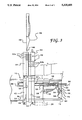
- FIG. 7 is a front elevational view of a plurality of connectors mounted side by side and in a stacked relationship to achieve high-density interconnection;
- FIG. 8 is a front exploded view of one embodiment of the plug used in the present invention.
- FIG. 9 is a perspective view of the fiber-to-fiber connector of the present invention.
- connector 10 is generally comprised of a transceiver housing 12, a receptacle or mounting frame 14 and a plug 16.
- Transceiver housing 12 is supported by a substrate 18 such as a circuit card which also includes several electronic components 20.
- Substrate 18 may be a cooling plate which is attached to the circuit card.
- Connector 10 is particularly suited for use in a high-density interconnection environment, such as a mainframe computer 22 depicted in FIG. 2.
- the exemplary computer 22 has a plurality of circuit cards 18, several or all of which may have connectors 10 attached at the edges thereof.
- the optical fibers 24 may be connected to other optoelectronic components on the same card or in the same panel, or the fibers may routed to other areas in the body 26 of computer 22, or completely exit body 26 and connect to peripheral or auxiliary devices.
- frame 14 may be integrally formed with housing 12 or removably attached thereto, but it is preferably attached instead to a vertical support bar 28 forming part of the chassis of computer 22.
- the chassis includes many such bars 28, evenly spaced along the edges of cards 18, or provided at specific locations.
- the position of frame 14 corresponds to the position of housing 12 when card 18 is fully inserted into brackets (not shown) which support cards 18 and are attached to bars 28. Attachment of frame 14 to bar 28 facilitates removal of the circuit card from the computer, as discussed further below.
- Mounting flanges 30 and 32 are laterally offset to allow the flanges of adjacent frames 14 to overlap and thus save space, similar to the flanges provided on the prior art electrical connectors mentioned hereinafter.
- a tongue-and-groove arrangement is formed by notches 34 in the sidewalls of frame 14 and splines 36 on plug 16, to allow plug 16 to slide within frame 14, and to ensure proper alignment of plug 16 in frame 14.
- Plug 16 may also be mechanically polarized, for example, by indenting the lower portions 38 of side walls 40 of plug 16.
- FIG. 8 illustrates the two-part construction of plug 16.
- Housing 12, frame 14, and plug 16 may be constructed of any durable material, preferably an injection-molded polymer such as polyester liquid crystral polymer (LCP).
- plug 16 includes a plurality of ferrules 42 (preferably ceramic) which contain the terminal ends of optical fibers 24.
- Housing 12 has an alignment block 43 along one edge thereof and plurality of holes 44 in block 43 extending generally perpendicular to the edge of housing 12, and ferrules 42 are positioned on plug 16 whereby they are generally aligned with holes 44.
- Holes 44 are advantageously provided with removable sleeves or bushings 46 which receive ferrules 42, and are adjustable for active alignment to an optoelectronic device 48 which is located in housing 12.
- Bushings 46 may be chamfered to facilitate insertion of ferrules 42.
- the connection between the ferrules and the optoelectronic components may be accomplished in several different ways.
- device 48 which may have an internal lens to directly couple to ferrule 42, is shown forcibly abutting ferrules 42; this arrangement is particularly suited for multimode applications.
- another electro-optical device $o has "pigtail" sections of fiber 52 terminating in other ferrules 54 which couple to ferrules 42 of plug 16; this arrangement is particularly suited for single mode applications.
- the optically active devices 48 and 52 may comprise any conventional optoelectronic components, including light-emitting diodes (LED's), laser diodes, photodetectors, etc.
- Presently preferred components include the laser diodes and photodetectors currently sold by British Telecommunications & DuPont Technologies of Kenntt Square, Pennsylvania, under part numbers LSC1300 and PDT0412, respectively.
- connector 10 may be designed for practically any number of fiber connections; for example, FIG. 1 shows a 4-plex connector, while FIG. 3 shows a duplex connector.
- the ferrule assembly is preferably pull proof. This is accomplished in the present invention by providing a ferrule assembly which includes a ferrule 42, a ferrule holder or collar $6, a spring 58, and a ferrule tailpiece or nut 60.
- the cable portion of a given fiber 24 is secured to tailpiece 60, such as by bonding or crimping.
- the fiber extends through tailpiece 60 and collar 56, terminating in ferrule 42.
- Tailpiece 60 has an annular flange 62 which serves as a stop to limit rearward movement of the ferrule assembly by abutting the inner rear wall 64 of plug 16. In this manner, any pulling force transmitted through the fiber optic cable is transferred to tailpiece 60 and the plug housing. Ferrule collar 56, which is spring-loaded against the proximate end of tailpiece 60, is thus unaffected.
- the ferrule collar and tailpiece are preferably constructed of polyetherimide.
- FIG. 3 also illustrates the use of a torsion latch member 66 which is used to releasably secure plug 16 in one or more positions relative to frame 14.
- Torsion member 66 which is constructed of a flexible, resilient material such as polyetherimide, has a boss or anchor 68 at one end which is fixed to the housing of plug 16.
- the free end 70 of torsion member 66 is provided with an appropriate structure to allow twisting of that end of member 66. While end 70 may be designed to mate with practically any tool, such as a screwdriver, it is preferably designed to mate with a special tool such as that shown in FIG. 4.
- Tool 72 has a tubular construction and bayonet-style cutouts 74 at one end which serve to catch pins 76 on end 70 of torsion member 66.
- the other end of tool 72 is provided with an adaptor head 78 having a hole 80 and a retaining screw 82 so that it may easily be attached to, e.g., a regular screwdriver.
- Tool 72 is preferably constructed of polyetherimide or metal.
- Torsion member 66 releasably fixes plug 16 to frame 14 by providing a tenon or tab 84 which fits into one or more slots 86 in the base Of frame 14 (see FIG. 1). In the relaxed state of member 66, tab 84 extends downwardly into one of these slots, but the tab is easily disengaged by twisting free end 70. When tab 84 is so disengaged, plug 16 is free to slide along frame 14. Stop blocks 88 (seen more clearly in FIG. 8), are integrally molded with plug 16 to limit the degree to which member 66 may be twisted.
- a releasable latching mechanism having more than one setting or position is advantageous in that connector 10 may be placed in an inoperative state, but plug 16 is still retained with the entire connector assembly in a retracted or storage position. This facilitates the removal of circuit card 18 while retaining plug 16 in position for quick reconnection.
- Provision of pins 76 and bayonet-style tool 72 makes it easy to move plug 16 between the operative and retracted positions and, furthermore, since most prior art fiber optic connectors require manual actuation to achieve the connection, the use of tool 72 overcomes the difficulty of disengaging the connectors in a high-density environment where many connectors may be spaced so closely as to preclude manual access.
- FIG. 3 further depicts the optional use of a shuttle system which is compatible with one particular prior art computer card using copper connectors 90 to provide electrical connections via wires 91.
- Connectors 90 have multiple sliding contacts 92, such as the connector sold by International Telephone and Telephone Co. under part no. 8911-263.
- This electrical connector has a notch on one side forming a U-shaped profile, and the contacts are free to slide from side-to-side within the notch.
- the contacts are in a first position 92a, one end of each contact extends slightly beyond the connector to touch a contact of another electrical connector 94 on the circuit card.
- the contacts are retracted, opening the circuit paths and physically disengaging connector 90 from the circuit card.
- Contacts 92 are moved from one position to another using an elongated actuator tool 96 similar to an oil pan dipstick.
- the terminal end 98 of tool 96 forms an inclined ramp having a narrow tip 100.
- Each of the contacts 92 have a small tab that extends into the notch of connector 90 and, as tool 96 is inserted into the notch, it forcibly urges the tabs to one side or another, depending upon the orientation of tool 96.
- a bank of connectors 90 may be quickly disengaged by simply pushing tool 96 through each of the connectors 90 on a given card 18.
- the fiber optic connector of the present invention may be made compatible with such a prior art copper connection system by simply providing a space or channel between the housing 12 and frame 14. There is, however, one major problem with such a design, relating to the fact that there is not much tolerance in the position of tip 100 with respect to the connector contacts 92. If such an open space is provided between housing 12 and frame 14, then terminal end 98 of tool 96 can have some freedom in lateral movement, meaning that tip 100 might not be properly oriented for another copper connector which follows connector 10. It is very likely that a computer circuit card utilizing the present invention would have such side-by-side copper and fiber connectors. In other words, tip 100 might jam against or damage the tab of the first contact 92 in any copper connector 90 which is adjacent to a fiber connector 10.
- the present invention provides a slider or shuttle 102 as shown in FIG. 5.
- Shuttle 102 is slidably interposed between housing 12 and frame 14, and has two grooves for receiving tool 96, forming an H-shaped profile having a central bar 104.
- Bar 104 has several holes therein, to allow passage of ferrules 42.
- the edge of housing 12 forms a shelf 106 to accommodate the base 108 of shuttle 102; the edge of frame 14 has a cavity 110 for receiving a portion of shuttle 102, and the sides of frame 14 have a notch 112 to allow passage of tool 96.
- each of the fiber optic Connectors 10 are first disengaged by using tool 72 to move each of the plugs 16 to their storage positions; this action retracts ferrules 42 from the shuttle area.
- Tool 96 is used to disconnect copper connectors 90, and the card may then be withdrawn from the chassis.
- the optoelectronics package located in housing 12 should have a minimal height.
- the presently preferred package design shown in FIG. 6 includes a substrate or printed circuit board (PCB) 114 which has discrete surface mount (electronic) components 116 attached to each side thereof.
- Metallic (aluminum) studs 118 may be provided for heat dissipation, and PCB 114 may be mounted to housing 12 using thermal transfer tape 120.
- the floor of housing 12 may also include a thermal stud 122.
- PCB 114 preferably is a multilayer fiberglass substrate having impedance controlled signal paths for high frequency performance, a woven ground and voltage plane design for improved thermal dissipation, and cavities for ultra-low profile surface mount application.
- connector 10 While the dimensions of connector 10 may vary considerably depending upon the application, the primary goal of the present invention is to provide a low-profile connector, having a thickness in the range of 2-8 mm, and preferably about 5 mm, in order to be compatible with existing computer systems wherein the spacing between circuit cards is about 6 mm.
- the width of connector 10 primarily depends upon the number of ferrules in plug 16; in an exemplary 4-plex connector, each of the transceiver housing 12, frame 14, and plug 16 have a width in the range of 20-40 mm, preferably about 30 mm.
- PCB 114 is very thin, about 2 mm thick. Due to the overall compactness of the design, combined with overlapping flanges 30 and 32, very high interconnection densities can be achieved. FIG.
- FIG. 7 illustrates how a plurality of connectors 10 may be mounted side by side and in a stacked relationship to achieve high-density interconnection. Densities of more than 1 connection per square centimeter, and as high as 2 connections per square centimeter, can be achieved, compared to 0.6 connections per square centimeter for conventional connectors. A ferrule-to-ferrule distance of as little as 2 mm can also be achieved.
- FIG. 9 illustrates how the connector 10 of the present invention may easily be adapted for fiber-to-fiber interconnection, facilitating such re-routing.
- Two existing plugs 16 may be interconnected by providing a coupling or receptacle 124 having two porches or ramps 126 which are essentially identical to frame 14.
- a boss or block 128 joins ramps 126, and has several holes 130 therein for receiving the ferrules.
- a bulkhead for many such fiber-to-fiber connections may be formed by stacking several such receptacles 124.
Abstract
Description
Claims (22)
Priority Applications (4)
| Application Number | Priority Date | Filing Date | Title |
|---|---|---|---|
| US07/964,913 US5325455A (en) | 1992-10-21 | 1992-10-21 | Fiber optic edge card connector |
| PCT/US1993/009000 WO1994009397A1 (en) | 1992-10-21 | 1993-09-22 | Fiber optic edge card connector |
| JP6510012A JPH08502371A (en) | 1992-10-21 | 1993-09-22 | Optical fiber edge card connector |
| EP94913428A EP0666997A1 (en) | 1992-10-21 | 1993-09-22 | Fiber optic edge card connector |
Applications Claiming Priority (1)
| Application Number | Priority Date | Filing Date | Title |
|---|---|---|---|
| US07/964,913 US5325455A (en) | 1992-10-21 | 1992-10-21 | Fiber optic edge card connector |
Publications (1)
| Publication Number | Publication Date |
|---|---|
| US5325455A true US5325455A (en) | 1994-06-28 |
Family
ID=25509151
Family Applications (1)
| Application Number | Title | Priority Date | Filing Date |
|---|---|---|---|
| US07/964,913 Expired - Fee Related US5325455A (en) | 1992-10-21 | 1992-10-21 | Fiber optic edge card connector |
Country Status (4)
| Country | Link |
|---|---|
| US (1) | US5325455A (en) |
| EP (1) | EP0666997A1 (en) |
| JP (1) | JPH08502371A (en) |
| WO (1) | WO1994009397A1 (en) |
Cited By (76)
| Publication number | Priority date | Publication date | Assignee | Title |
|---|---|---|---|---|
| US5394503A (en) * | 1993-10-08 | 1995-02-28 | Data Switch Corporation | Optical fiber connection monitoring apparatus, patch panel control system and method of using same |
| US5428702A (en) * | 1991-04-30 | 1995-06-27 | Framatome Connectors Deutschland Gmbh | Optical waveguide connector |
| US5561727A (en) * | 1994-02-15 | 1996-10-01 | Sumitomo Electric Industries, Ltd. | Card-shaped optical data link device |
| US5563971A (en) * | 1995-04-28 | 1996-10-08 | The Whitaker Corporation | Floating bottleneck for multiple position fiber optic receptacle |
| US5574814A (en) * | 1995-01-31 | 1996-11-12 | Microelectronics And Computer Technology Corporation | Parallel optical transceiver link |
| US5574812A (en) * | 1993-01-26 | 1996-11-12 | Siemens Aktiengesellscnaft | Holder arrangement for optical connectors or the like |
| US5631807A (en) * | 1995-01-20 | 1997-05-20 | Minnesota Mining And Manufacturing Company | Electronic circuit structure with aperture suspended component |
| US5671311A (en) * | 1994-11-15 | 1997-09-23 | The Whitaker Corporation | Sealed multiposition fiber optic connector |
| WO1997041472A1 (en) * | 1996-04-30 | 1997-11-06 | Next Level Communications | Optical network unit (onu) mechanical enclosure |
| US5796896A (en) * | 1996-03-14 | 1998-08-18 | Minnesota Mining And Manufacturing Company | Multi-ferrule fiber optic connector for high density backplane applications |
| US5970193A (en) * | 1996-10-24 | 1999-10-19 | Nortel Networks Corporation | Data communications structures relating to data shelf configurations |
| US6005991A (en) * | 1997-11-26 | 1999-12-21 | Us Conec Ltd | Printed circuit board assembly having a flexible optical circuit and associated fabrication method |
| US6062739A (en) * | 1997-07-25 | 2000-05-16 | Raytheon Company | Fiber optic connector |
| USRE36820E (en) | 1995-01-13 | 2000-08-15 | Methode Electronics, Inc. | Removable optoelectronic module |
| US6179627B1 (en) | 1998-04-22 | 2001-01-30 | Stratos Lightwave, Inc. | High speed interface converter module |
| US6201704B1 (en) | 1995-01-13 | 2001-03-13 | Stratos Lightwave, Inc. | Transceive module with EMI shielding |
| US6203333B1 (en) | 1998-04-22 | 2001-03-20 | Stratos Lightwave, Inc. | High speed interface converter module |
| US6220878B1 (en) | 1995-10-04 | 2001-04-24 | Methode Electronics, Inc. | Optoelectronic module with grounding means |
| US6224268B1 (en) * | 1998-04-23 | 2001-05-01 | The Whitaker Corporation | Plug housing with attached cantilevered latch for a fiber optic connector |
| US6259856B1 (en) * | 1999-03-04 | 2001-07-10 | Lucent Technologies, Inc. | Small form factor multi-fiber optical connectors and methods for making same |
| US20010030789A1 (en) * | 1999-05-27 | 2001-10-18 | Wenbin Jiang | Method and apparatus for fiber optic modules |
| US20010041034A1 (en) * | 2000-05-12 | 2001-11-15 | Junichi Sasaki | Substrate, optical fiber connection end member, optical element housing member, and method of fabrication of an optical module and the substrate |
| US6379053B1 (en) | 2000-05-30 | 2002-04-30 | Infineon Technologies North America Corp. | Multi-fiber fiber optic connectors |
| US6394664B1 (en) * | 1998-01-31 | 2002-05-28 | Mitel Semiconductor Ab | Fiber optic module |
| US20020131730A1 (en) * | 2001-03-15 | 2002-09-19 | Agilent Technologies, Inc. | Novel fiber optic transceiver module |
| US20020151226A1 (en) * | 2001-01-26 | 2002-10-17 | Boe Craig L. | Apparatuses and methods for preventing disengagement of electrical connectors in the assembly of computers |
| US20030020986A1 (en) * | 1999-05-27 | 2003-01-30 | Pang Ron Cheng Chuan | Method and apparatus for pluggable fiber optic modules |
| US20030026556A1 (en) * | 2001-08-03 | 2003-02-06 | National Semiconductor Corporation | Optical sub-assembly for optoelectronic modules |
| US20030057535A1 (en) * | 2001-09-24 | 2003-03-27 | National Semiconductor Corporation | Techniques for attaching rotated photonic devices to an optical sub-assembly in an optoelectronic package |
| US20030075355A1 (en) * | 2000-12-26 | 2003-04-24 | Anderson Gene R. | An apparatus and method of using flexible printed circuit board in optical transceiver device |
| US20030087505A1 (en) * | 2000-11-14 | 2003-05-08 | Peter Deane | Method and apparatus for adapting a miniature form-factor connector to a standard format fiber optic connector plug |
| US6582133B2 (en) | 2001-05-30 | 2003-06-24 | Tropic Networks Inc. | Module and method for interconnecting optoelectronic cards |
| US20030123813A1 (en) * | 1999-12-31 | 2003-07-03 | Giuseppe Ravasio | Network for distributing signals to a plurality of users |
| US6628860B1 (en) * | 2000-06-05 | 2003-09-30 | Infineon Technologies North America Corp. | Fiber optic connector systems |
| US20030201123A1 (en) * | 2002-04-30 | 2003-10-30 | Kris Kistner | Electrical connector pad assembly for printed circuit board |
| US6692159B2 (en) | 2001-04-14 | 2004-02-17 | E20 Communications, Inc. | De-latching mechanisms for fiber optic modules |
| US20040120658A1 (en) * | 2002-12-19 | 2004-06-24 | Mcfarland Jonathan | Apparatus and method of packaging two dimensional photonic array devices |
| US20040146253A1 (en) * | 2003-01-28 | 2004-07-29 | Wang Charlie X. | Method and apparatus for parallel optical transceiver module assembly |
| US6796715B2 (en) | 2001-04-14 | 2004-09-28 | E20 Communications, Inc. | Fiber optic modules with pull-action de-latching mechanisms |
| US6799902B2 (en) | 2000-12-26 | 2004-10-05 | Emcore Corporation | Optoelectronic mounting structure |
| US6830382B1 (en) * | 2001-12-20 | 2004-12-14 | National Semiconductor Corporation | Miniature form-factor connecter for fiber optic modules |
| US20050013560A1 (en) * | 2003-07-15 | 2005-01-20 | National Semiconductor Corporation | Opto-electronic module form factor having adjustable optical plane height |
| US6846115B1 (en) | 2001-01-29 | 2005-01-25 | Jds Uniphase Corporation | Methods, apparatus, and systems of fiber optic modules, elastomeric connections, and retention mechanisms therefor |
| US20050018972A1 (en) * | 2000-12-26 | 2005-01-27 | Anderson Gene R. | Housing and mounting structure |
| US6905260B2 (en) | 2000-12-26 | 2005-06-14 | Emcore Corporation | Method and apparatus for coupling optical elements to optoelectronic devices for manufacturing optical transceiver modules |
| US20050286839A1 (en) * | 2004-06-16 | 2005-12-29 | Sumitomo Electric Industries, Ltd. | Optical subassembly and optical transceiver installing the same |
| US7021836B2 (en) | 2000-12-26 | 2006-04-04 | Emcore Corporation | Attenuator and conditioner |
| US7023705B2 (en) | 2001-08-03 | 2006-04-04 | National Semiconductor Corporation | Ceramic optical sub-assembly for optoelectronic modules |
| US20060093287A1 (en) * | 2004-10-05 | 2006-05-04 | Satoshi Yoshikawa | Heat dissipating mechanism of a pluggable optical transceiver |
| US20060093305A1 (en) * | 2004-10-29 | 2006-05-04 | Agilent Technologies, Inc. | Electro-optical subassemblies and method for assembly thereof |
| US20060098923A1 (en) * | 2003-04-30 | 2006-05-11 | Fujikura Ltd. | Optical connector assembly, connector holder, and optical connector |
| US20060140534A1 (en) * | 2001-08-03 | 2006-06-29 | National Semiconductor Corporation | Ceramic optical sub-assembly for optoelectronic modules |
| US7090509B1 (en) * | 1999-06-11 | 2006-08-15 | Stratos International, Inc. | Multi-port pluggable transceiver (MPPT) with multiple LC duplex optical receptacles |
| US7101091B2 (en) * | 2001-02-21 | 2006-09-05 | Zarlink Semiconductor, Inc. | Apparatus for coupling a fiber optic cable to an optoelectronic device, a system including the apparatus, and a method of forming the same |
| US20060210225A1 (en) * | 2003-04-30 | 2006-09-21 | Kunihiko Fujiwara | Optical transceiver and optical connector |
| US20070189673A1 (en) * | 2004-10-05 | 2007-08-16 | Satoshi Yoshikawa | Optical transceiver with a pluggable function |
| US20070230876A1 (en) * | 2006-03-29 | 2007-10-04 | Infineon Technologies Ag | Device and Method for Data Transmission Between Structural Units Connected by an Articulated Joint |
| US20080095502A1 (en) * | 2006-10-19 | 2008-04-24 | Mccolloch Laurence Ray | Stackable multi-optical fiber connector modules and devices for aligning sets of the stackable multi-optical fiber connector modules and coupling optical signals between them |
| US20080095506A1 (en) * | 2006-10-19 | 2008-04-24 | Mccolloch Laurence Ray | multi-optical fiber connector module for use with a transceiver module and method for coupling optical signals between the transceiver module and multiple optical fibers |
| US20080095501A1 (en) * | 2006-10-19 | 2008-04-24 | Mccolloch Laurence Ray | Stackable multi-optical fiber connector modules and devices for aligning sets of the stackable multi-optical fiber connector modules and coupling optical signals between them |
| US20080131135A1 (en) * | 2006-12-01 | 2008-06-05 | Dugan Richard W | Optical Transceiver Module |
| CN100570420C (en) * | 2006-10-19 | 2009-12-16 | 安华高科技光纤Ip(新加坡)私人有限公司 | Can pile up the multiple fiber optical connector module, make it to aim at the also device of coupling optical signal |
| US20100296778A1 (en) * | 2009-05-19 | 2010-11-25 | Japan Aviation Electronics Industry, Limited | Optical connector |
| US20120195564A1 (en) * | 2011-01-27 | 2012-08-02 | Sagi Varghese Mathai | Waveguide arrays |
| US20130011103A1 (en) * | 2011-07-05 | 2013-01-10 | Hon Hai Precision Industry Co., Ltd. | Optoelectronic connector having improved optical module |
| WO2013044041A1 (en) * | 2011-09-23 | 2013-03-28 | Tyco Electronics Nederland B.V. | Optical interface for bidirectional communications |
| US20130195396A1 (en) * | 2012-01-27 | 2013-08-01 | Telefonaktiebolaget L M Ericsson (Publ) | Optical physical interface module |
| US20130343066A1 (en) * | 2012-06-22 | 2013-12-26 | Witt C. Guinn | Laser instrumentation bracket |
| US20140270654A1 (en) * | 2013-03-18 | 2014-09-18 | Hon Hai Precision Industry Co., Ltd. | Optical fiber assembly with replaceable connecting element |
| US20160116697A1 (en) * | 2014-10-27 | 2016-04-28 | Adc Telecommunications, Inc. | Splice module for fiber blade |
| US20160299297A1 (en) * | 2013-06-28 | 2016-10-13 | Toto Ltd. | Optical receptacle, ferrule, and plug ferrule |
| US9690065B2 (en) | 2014-09-12 | 2017-06-27 | Panduit Corp. | High density fiber enclosure and method |
| US20180062329A1 (en) * | 2015-05-01 | 2018-03-01 | Ab Connectors Ltd | Method of mounting an electrical connector to flexible planar material and apparatus therefor |
| US10215944B2 (en) | 2016-06-30 | 2019-02-26 | Panduit Corp. | Modular fiber optic tray |
| US10677999B2 (en) * | 2018-08-22 | 2020-06-09 | Hewlett Packard Enterprise Development Lp | Duplex-modulo optical blindmate connector having a carrier plate and connector housing |
| US11223155B1 (en) * | 2020-10-20 | 2022-01-11 | Deere & Company | Electrical connector cavity plug and cover assembly |
Families Citing this family (5)
| Publication number | Priority date | Publication date | Assignee | Title |
|---|---|---|---|---|
| WO1996000920A1 (en) * | 1994-06-30 | 1996-01-11 | The Whitaker Corporation | Optoelectronic package and bidirectional optical transceiver for use therein |
| JP3927363B2 (en) * | 2000-11-01 | 2007-06-06 | 株式会社日立製作所 | Optical connection device |
| FR2967262B1 (en) * | 2010-11-08 | 2013-05-31 | Nicomatic Sa | MICRO-MILLIMETRIC CONNECTOR |
| FR3001046B1 (en) * | 2013-01-11 | 2016-03-25 | Nexans | DEVICE FOR DISASSEMBLING A CONNECTION IN AN OPTICAL CONNECTION MODULE |
| CN107576462B (en) * | 2017-08-29 | 2019-11-01 | 广东亨通光电科技有限公司 | A kind of LC optical fiber connector elasticity testing device |
Citations (20)
| Publication number | Priority date | Publication date | Assignee | Title |
|---|---|---|---|---|
| US4611887A (en) * | 1983-02-24 | 1986-09-16 | Amp Incorporated | Fiber optic connector assembly and wall outlet thereof |
| US4678264A (en) * | 1983-03-30 | 1987-07-07 | Amp Incorporated | Electrical and fiber optic connector assembly |
| US4762388A (en) * | 1984-03-19 | 1988-08-09 | E. I. Du Pont De Nemours And Company | Optical connector receptacle and plug |
| US4779950A (en) * | 1984-04-03 | 1988-10-25 | Thomas & Betts Corporation | Connection apparatus for optical fibers |
| US4807955A (en) * | 1987-08-06 | 1989-02-28 | Amp Incorporated | Opto-electrical connecting means |
| US4840451A (en) * | 1987-12-08 | 1989-06-20 | Molex Incorporated | Shielded fiber optic connector assembly |
| US4877302A (en) * | 1987-04-09 | 1989-10-31 | U.S. Philips Corp. | Plug connector for the ends of two light waveguides |
| US4944568A (en) * | 1989-09-05 | 1990-07-31 | Molex Incorporated | Fiber optic connector assembly |
| US4979792A (en) * | 1989-08-21 | 1990-12-25 | Amp Incorporated | Means for keeping keying elements with a connector assembly |
| US4986762A (en) * | 1989-08-15 | 1991-01-22 | Minnesota Mining And Manufacturing Company | Termination module for use in an array of modules |
| US5013247A (en) * | 1989-10-16 | 1991-05-07 | International Business Machines Corporation | Fiber optic connector assembly adapted for providing circuit card charging |
| US5016968A (en) * | 1989-09-27 | 1991-05-21 | At&T Bell Laboratories | Duplex optical fiber connector and cables terminated therewith |
| US5104243A (en) * | 1990-04-23 | 1992-04-14 | E. I. Du Pont De Nemours And Company | Device for electro-optical signal conversion |
| US5155784A (en) * | 1990-11-07 | 1992-10-13 | Bicc Plc | Optical connection to backplanes |
| US5166995A (en) * | 1984-06-08 | 1992-11-24 | Amp Incorporated | Polarized connector |
| US5199093A (en) * | 1990-05-22 | 1993-03-30 | Bicc Plc. | Multi-part optical fibre connectors |
| US5204925A (en) * | 1991-09-11 | 1993-04-20 | At&T Bell Laboratories | Optical interconnection of circuit packs |
| US5230030A (en) * | 1992-04-24 | 1993-07-20 | Motorola, Inc. | Interface coupling electronic circuitry |
| US5239606A (en) * | 1990-11-19 | 1993-08-24 | Japan Aviation Electronics Industry, Limited | Optical connector comprising an optical connection adapter with means for connection/disconnection of an optical contact |
| US5241614A (en) * | 1991-04-29 | 1993-08-31 | International Business Machines Corporation | Apparatus and a method for an optical fiber interface |
Family Cites Families (8)
| Publication number | Priority date | Publication date | Assignee | Title |
|---|---|---|---|---|
| US4186996A (en) * | 1978-09-22 | 1980-02-05 | Amp Incorporated | Optic adaptor junction |
| CA1196221A (en) * | 1981-03-16 | 1985-11-05 | Terry P. Bowen | Optical waveguide connector |
| JPS5890607A (en) * | 1981-11-25 | 1983-05-30 | Mitsubishi Electric Corp | Coupling structure of optical circuit |
| US4515434A (en) * | 1983-03-09 | 1985-05-07 | Allied Corporation | Fiber optic connector |
| US4993803A (en) * | 1989-05-18 | 1991-02-19 | General Motors Corporation | Electro-optical header connector |
| US5121454A (en) * | 1989-11-24 | 1992-06-09 | Nippon Telegraph And Telephone Corporation | Optical connector |
| GB2239104B (en) * | 1989-11-28 | 1993-11-24 | Kel Kk | Multi-way electro-optic connector assemblies and optical fiber ferrule assemblies therefor |
| US5202943A (en) * | 1991-10-04 | 1993-04-13 | International Business Machines Corporation | Optoelectronic assembly with alignment member |
-
1992
- 1992-10-21 US US07/964,913 patent/US5325455A/en not_active Expired - Fee Related
-
1993
- 1993-09-22 WO PCT/US1993/009000 patent/WO1994009397A1/en not_active Application Discontinuation
- 1993-09-22 EP EP94913428A patent/EP0666997A1/en not_active Ceased
- 1993-09-22 JP JP6510012A patent/JPH08502371A/en active Pending
Patent Citations (20)
| Publication number | Priority date | Publication date | Assignee | Title |
|---|---|---|---|---|
| US4611887A (en) * | 1983-02-24 | 1986-09-16 | Amp Incorporated | Fiber optic connector assembly and wall outlet thereof |
| US4678264A (en) * | 1983-03-30 | 1987-07-07 | Amp Incorporated | Electrical and fiber optic connector assembly |
| US4762388A (en) * | 1984-03-19 | 1988-08-09 | E. I. Du Pont De Nemours And Company | Optical connector receptacle and plug |
| US4779950A (en) * | 1984-04-03 | 1988-10-25 | Thomas & Betts Corporation | Connection apparatus for optical fibers |
| US5166995A (en) * | 1984-06-08 | 1992-11-24 | Amp Incorporated | Polarized connector |
| US4877302A (en) * | 1987-04-09 | 1989-10-31 | U.S. Philips Corp. | Plug connector for the ends of two light waveguides |
| US4807955A (en) * | 1987-08-06 | 1989-02-28 | Amp Incorporated | Opto-electrical connecting means |
| US4840451A (en) * | 1987-12-08 | 1989-06-20 | Molex Incorporated | Shielded fiber optic connector assembly |
| US4986762A (en) * | 1989-08-15 | 1991-01-22 | Minnesota Mining And Manufacturing Company | Termination module for use in an array of modules |
| US4979792A (en) * | 1989-08-21 | 1990-12-25 | Amp Incorporated | Means for keeping keying elements with a connector assembly |
| US4944568A (en) * | 1989-09-05 | 1990-07-31 | Molex Incorporated | Fiber optic connector assembly |
| US5016968A (en) * | 1989-09-27 | 1991-05-21 | At&T Bell Laboratories | Duplex optical fiber connector and cables terminated therewith |
| US5013247A (en) * | 1989-10-16 | 1991-05-07 | International Business Machines Corporation | Fiber optic connector assembly adapted for providing circuit card charging |
| US5104243A (en) * | 1990-04-23 | 1992-04-14 | E. I. Du Pont De Nemours And Company | Device for electro-optical signal conversion |
| US5199093A (en) * | 1990-05-22 | 1993-03-30 | Bicc Plc. | Multi-part optical fibre connectors |
| US5155784A (en) * | 1990-11-07 | 1992-10-13 | Bicc Plc | Optical connection to backplanes |
| US5239606A (en) * | 1990-11-19 | 1993-08-24 | Japan Aviation Electronics Industry, Limited | Optical connector comprising an optical connection adapter with means for connection/disconnection of an optical contact |
| US5241614A (en) * | 1991-04-29 | 1993-08-31 | International Business Machines Corporation | Apparatus and a method for an optical fiber interface |
| US5204925A (en) * | 1991-09-11 | 1993-04-20 | At&T Bell Laboratories | Optical interconnection of circuit packs |
| US5230030A (en) * | 1992-04-24 | 1993-07-20 | Motorola, Inc. | Interface coupling electronic circuitry |
Cited By (147)
| Publication number | Priority date | Publication date | Assignee | Title |
|---|---|---|---|---|
| US5428702A (en) * | 1991-04-30 | 1995-06-27 | Framatome Connectors Deutschland Gmbh | Optical waveguide connector |
| US5574812A (en) * | 1993-01-26 | 1996-11-12 | Siemens Aktiengesellscnaft | Holder arrangement for optical connectors or the like |
| US5394503A (en) * | 1993-10-08 | 1995-02-28 | Data Switch Corporation | Optical fiber connection monitoring apparatus, patch panel control system and method of using same |
| US5561727A (en) * | 1994-02-15 | 1996-10-01 | Sumitomo Electric Industries, Ltd. | Card-shaped optical data link device |
| US6033125A (en) * | 1994-11-15 | 2000-03-07 | The Whitaker Corporation | Sealed multiposition fiber optic connector |
| US5671311A (en) * | 1994-11-15 | 1997-09-23 | The Whitaker Corporation | Sealed multiposition fiber optic connector |
| US6267606B1 (en) * | 1995-01-13 | 2001-07-31 | Stratos Lightwave, Inc. | Removable transceiver module and receptacle |
| US6201704B1 (en) | 1995-01-13 | 2001-03-13 | Stratos Lightwave, Inc. | Transceive module with EMI shielding |
| USRE36820E (en) | 1995-01-13 | 2000-08-15 | Methode Electronics, Inc. | Removable optoelectronic module |
| US5689600A (en) * | 1995-01-20 | 1997-11-18 | Minnesota Mining And Manufacturing Company | Electronic circuit structure |
| US5631807A (en) * | 1995-01-20 | 1997-05-20 | Minnesota Mining And Manufacturing Company | Electronic circuit structure with aperture suspended component |
| US5574814A (en) * | 1995-01-31 | 1996-11-12 | Microelectronics And Computer Technology Corporation | Parallel optical transceiver link |
| US5563971A (en) * | 1995-04-28 | 1996-10-08 | The Whitaker Corporation | Floating bottleneck for multiple position fiber optic receptacle |
| US6220878B1 (en) | 1995-10-04 | 2001-04-24 | Methode Electronics, Inc. | Optoelectronic module with grounding means |
| US5796896A (en) * | 1996-03-14 | 1998-08-18 | Minnesota Mining And Manufacturing Company | Multi-ferrule fiber optic connector for high density backplane applications |
| US5828807A (en) * | 1996-04-30 | 1998-10-27 | Next Level Communications | Optical network unit (ONU) mechanical enclosure |
| US5982972A (en) * | 1996-04-30 | 1999-11-09 | Next Level Communications | Line card for optical network unit mechanical enclosure |
| WO1997041472A1 (en) * | 1996-04-30 | 1997-11-06 | Next Level Communications | Optical network unit (onu) mechanical enclosure |
| US5970193A (en) * | 1996-10-24 | 1999-10-19 | Nortel Networks Corporation | Data communications structures relating to data shelf configurations |
| US6062739A (en) * | 1997-07-25 | 2000-05-16 | Raytheon Company | Fiber optic connector |
| US6005991A (en) * | 1997-11-26 | 1999-12-21 | Us Conec Ltd | Printed circuit board assembly having a flexible optical circuit and associated fabrication method |
| US6394664B1 (en) * | 1998-01-31 | 2002-05-28 | Mitel Semiconductor Ab | Fiber optic module |
| US6203333B1 (en) | 1998-04-22 | 2001-03-20 | Stratos Lightwave, Inc. | High speed interface converter module |
| US6179627B1 (en) | 1998-04-22 | 2001-01-30 | Stratos Lightwave, Inc. | High speed interface converter module |
| US6224268B1 (en) * | 1998-04-23 | 2001-05-01 | The Whitaker Corporation | Plug housing with attached cantilevered latch for a fiber optic connector |
| US6259856B1 (en) * | 1999-03-04 | 2001-07-10 | Lucent Technologies, Inc. | Small form factor multi-fiber optical connectors and methods for making same |
| US20030020986A1 (en) * | 1999-05-27 | 2003-01-30 | Pang Ron Cheng Chuan | Method and apparatus for pluggable fiber optic modules |
| US20010030789A1 (en) * | 1999-05-27 | 2001-10-18 | Wenbin Jiang | Method and apparatus for fiber optic modules |
| USRE41147E1 (en) * | 1999-05-27 | 2010-02-23 | Jds Uniphase Corporation | Method and apparatus for pluggable fiber optic modules |
| US7116912B2 (en) | 1999-05-27 | 2006-10-03 | Jds Uniphase Corporation | Method and apparatus for pluggable fiber optic modules |
| US7090509B1 (en) * | 1999-06-11 | 2006-08-15 | Stratos International, Inc. | Multi-port pluggable transceiver (MPPT) with multiple LC duplex optical receptacles |
| US6909821B2 (en) * | 1999-12-31 | 2005-06-21 | Pirelli Cavi E Sistemi S.P.A. | Network for distributing signals to a plurality of users |
| US20030123813A1 (en) * | 1999-12-31 | 2003-07-03 | Giuseppe Ravasio | Network for distributing signals to a plurality of users |
| US7204646B2 (en) | 2000-05-12 | 2007-04-17 | Nec Corporation | Substrate, optical fiber connection end member, optical element housing member, and method of fabrication of an optical module and the substrate |
| US20060110107A1 (en) * | 2000-05-12 | 2006-05-25 | Nec Corporation | Substrate, optical fiber connection end member, optical element housing member, and method of fabrication of an optical module and the substrate |
| US20010041034A1 (en) * | 2000-05-12 | 2001-11-15 | Junichi Sasaki | Substrate, optical fiber connection end member, optical element housing member, and method of fabrication of an optical module and the substrate |
| US6964527B2 (en) * | 2000-05-12 | 2005-11-15 | Nec Corporation | Substrate, optical fiber connection end member, optical element housing member, and method of fabrication of an optical module and the substrate |
| US6994479B2 (en) | 2000-05-12 | 2006-02-07 | ′NEC Corporation | Substrate, optical fiber connection end member, optical element housing member, and method of fabrication of an optical module and the substrate |
| US6379053B1 (en) | 2000-05-30 | 2002-04-30 | Infineon Technologies North America Corp. | Multi-fiber fiber optic connectors |
| US6628860B1 (en) * | 2000-06-05 | 2003-09-30 | Infineon Technologies North America Corp. | Fiber optic connector systems |
| US20030087505A1 (en) * | 2000-11-14 | 2003-05-08 | Peter Deane | Method and apparatus for adapting a miniature form-factor connector to a standard format fiber optic connector plug |
| US6802653B2 (en) * | 2000-11-14 | 2004-10-12 | National Semiconductor Corporation | Method and apparatus for adapting a miniature form-factor connector to a standard format fiber optic connector plug |
| US6867377B2 (en) | 2000-12-26 | 2005-03-15 | Emcore Corporation | Apparatus and method of using flexible printed circuit board in optical transceiver device |
| US20030075355A1 (en) * | 2000-12-26 | 2003-04-24 | Anderson Gene R. | An apparatus and method of using flexible printed circuit board in optical transceiver device |
| US6799902B2 (en) | 2000-12-26 | 2004-10-05 | Emcore Corporation | Optoelectronic mounting structure |
| US6863444B2 (en) | 2000-12-26 | 2005-03-08 | Emcore Corporation | Housing and mounting structure |
| US6905260B2 (en) | 2000-12-26 | 2005-06-14 | Emcore Corporation | Method and apparatus for coupling optical elements to optoelectronic devices for manufacturing optical transceiver modules |
| US20050018972A1 (en) * | 2000-12-26 | 2005-01-27 | Anderson Gene R. | Housing and mounting structure |
| US7021836B2 (en) | 2000-12-26 | 2006-04-04 | Emcore Corporation | Attenuator and conditioner |
| US6823588B2 (en) * | 2001-01-26 | 2004-11-30 | Micron Technology, Inc. | Methods for preventing disengagement of electrical connectors in the assembly of computers |
| US7107675B2 (en) * | 2001-01-26 | 2006-09-19 | Micron Technology, Inc. | Methods for retaining an electrical connector in a receptacle on an electrical component in a computer |
| US20020151226A1 (en) * | 2001-01-26 | 2002-10-17 | Boe Craig L. | Apparatuses and methods for preventing disengagement of electrical connectors in the assembly of computers |
| US7614149B2 (en) * | 2001-01-26 | 2009-11-10 | Micron Technology, Inc. | Methods for assembling computers |
| US7707718B2 (en) | 2001-01-26 | 2010-05-04 | Micron Technology, Inc. | Methods for assembling computers |
| US20070002530A1 (en) * | 2001-01-26 | 2007-01-04 | Micron Technology, Inc. | Apparatuses and methods for preventing disengagement of electrical connectors in the assembly of computers |
| US20050026493A1 (en) * | 2001-01-26 | 2005-02-03 | Boe Craig L. | Apparatuses and methods for preventing disengagement of electrical connectors in the assembly of computers |
| US20060268506A1 (en) * | 2001-01-26 | 2006-11-30 | Micron Technology, Inc. | Apparatus and methods for preventing disengagement of electrical connectors in the assembly of computers |
| US6846115B1 (en) | 2001-01-29 | 2005-01-25 | Jds Uniphase Corporation | Methods, apparatus, and systems of fiber optic modules, elastomeric connections, and retention mechanisms therefor |
| US7101091B2 (en) * | 2001-02-21 | 2006-09-05 | Zarlink Semiconductor, Inc. | Apparatus for coupling a fiber optic cable to an optoelectronic device, a system including the apparatus, and a method of forming the same |
| US20020131730A1 (en) * | 2001-03-15 | 2002-09-19 | Agilent Technologies, Inc. | Novel fiber optic transceiver module |
| US6811326B2 (en) * | 2001-03-15 | 2004-11-02 | Agilent Technologies, Inc. | Fiber optic transceiver module |
| US6832856B2 (en) | 2001-04-14 | 2004-12-21 | E2O Communications, Inc. | De-latching mechanisms for fiber optic modules |
| US6796715B2 (en) | 2001-04-14 | 2004-09-28 | E20 Communications, Inc. | Fiber optic modules with pull-action de-latching mechanisms |
| US6811317B2 (en) | 2001-04-14 | 2004-11-02 | Jds Uniphase Corporation | De-latching lever actuator for fiber optic modules |
| US6692159B2 (en) | 2001-04-14 | 2004-02-17 | E20 Communications, Inc. | De-latching mechanisms for fiber optic modules |
| US6814502B2 (en) | 2001-04-14 | 2004-11-09 | Jds Uniphase Corporation | De-latching mechanisms for fiber optic modules |
| US6582133B2 (en) | 2001-05-30 | 2003-06-24 | Tropic Networks Inc. | Module and method for interconnecting optoelectronic cards |
| US6916121B2 (en) | 2001-08-03 | 2005-07-12 | National Semiconductor Corporation | Optical sub-assembly for optoelectronic modules |
| US20030026556A1 (en) * | 2001-08-03 | 2003-02-06 | National Semiconductor Corporation | Optical sub-assembly for optoelectronic modules |
| US7023705B2 (en) | 2001-08-03 | 2006-04-04 | National Semiconductor Corporation | Ceramic optical sub-assembly for optoelectronic modules |
| US7086788B2 (en) | 2001-08-03 | 2006-08-08 | National Semiconductor Corporation | Optical sub-assembly for opto-electronic modules |
| US7269027B2 (en) | 2001-08-03 | 2007-09-11 | National Semiconductor Corporation | Ceramic optical sub-assembly for optoelectronic modules |
| US20060140534A1 (en) * | 2001-08-03 | 2006-06-29 | National Semiconductor Corporation | Ceramic optical sub-assembly for optoelectronic modules |
| US20030057535A1 (en) * | 2001-09-24 | 2003-03-27 | National Semiconductor Corporation | Techniques for attaching rotated photonic devices to an optical sub-assembly in an optoelectronic package |
| US6973225B2 (en) | 2001-09-24 | 2005-12-06 | National Semiconductor Corporation | Techniques for attaching rotated photonic devices to an optical sub-assembly in an optoelectronic package |
| US6830382B1 (en) * | 2001-12-20 | 2004-12-14 | National Semiconductor Corporation | Miniature form-factor connecter for fiber optic modules |
| US20030201123A1 (en) * | 2002-04-30 | 2003-10-30 | Kris Kistner | Electrical connector pad assembly for printed circuit board |
| US6828513B2 (en) | 2002-04-30 | 2004-12-07 | Texas Instruments Incorporated | Electrical connector pad assembly for printed circuit board |
| US20040120658A1 (en) * | 2002-12-19 | 2004-06-24 | Mcfarland Jonathan | Apparatus and method of packaging two dimensional photonic array devices |
| US6960031B2 (en) * | 2002-12-19 | 2005-11-01 | Primarion, Inc. | Apparatus and method of packaging two dimensional photonic array devices |
| US6863453B2 (en) | 2003-01-28 | 2005-03-08 | Emcore Corporation | Method and apparatus for parallel optical transceiver module assembly |
| US20040146253A1 (en) * | 2003-01-28 | 2004-07-29 | Wang Charlie X. | Method and apparatus for parallel optical transceiver module assembly |
| US20060098923A1 (en) * | 2003-04-30 | 2006-05-11 | Fujikura Ltd. | Optical connector assembly, connector holder, and optical connector |
| US20090196556A1 (en) * | 2003-04-30 | 2009-08-06 | Nec Corporation | Optical transceiver and optical connector |
| US20060210225A1 (en) * | 2003-04-30 | 2006-09-21 | Kunihiko Fujiwara | Optical transceiver and optical connector |
| US7534052B2 (en) | 2003-04-30 | 2009-05-19 | Fujikura Ltd. | Optical transceiver and optical connector |
| US7918610B2 (en) | 2003-04-30 | 2011-04-05 | Fujikura Ltd. | Optical transceiver and optical connector |
| US7287914B2 (en) * | 2003-04-30 | 2007-10-30 | Fujikura Ltd. | Optical connector assembly, connector holder, and optical connector |
| US7156562B2 (en) | 2003-07-15 | 2007-01-02 | National Semiconductor Corporation | Opto-electronic module form factor having adjustable optical plane height |
| US20050013560A1 (en) * | 2003-07-15 | 2005-01-20 | National Semiconductor Corporation | Opto-electronic module form factor having adjustable optical plane height |
| US7280724B2 (en) * | 2004-06-16 | 2007-10-09 | Sumitomo Electric Industries, Ltd. | Optical subassembly and optical transceiver installing the same |
| US20050286839A1 (en) * | 2004-06-16 | 2005-12-29 | Sumitomo Electric Industries, Ltd. | Optical subassembly and optical transceiver installing the same |
| US20070189673A1 (en) * | 2004-10-05 | 2007-08-16 | Satoshi Yoshikawa | Optical transceiver with a pluggable function |
| US20060093287A1 (en) * | 2004-10-05 | 2006-05-04 | Satoshi Yoshikawa | Heat dissipating mechanism of a pluggable optical transceiver |
| US7416353B2 (en) * | 2004-10-05 | 2008-08-26 | Sumitomo Electric Industries, Ltd. | Heat dissipating mechanism of a pluggable optical transceiver |
| US7406230B2 (en) * | 2004-10-05 | 2008-07-29 | Sumitomo Electric Industries, Ltd. | Optical transceiver with a pluggable function |
| US7491001B2 (en) | 2004-10-29 | 2009-02-17 | Avago Technologies General Ip (Singapore) Pte. Ltd. | Electro-optical subassemblies and method for assembly thereof |
| US7149405B2 (en) * | 2004-10-29 | 2006-12-12 | Avago Technologies General Ip (Singapore) Pte. Ltd. | Electro-optical subassemblies and method for assembly thereof |
| US20060093305A1 (en) * | 2004-10-29 | 2006-05-04 | Agilent Technologies, Inc. | Electro-optical subassemblies and method for assembly thereof |
| US7413353B2 (en) * | 2006-03-29 | 2008-08-19 | Infineon Technologies Ag | Device and method for data transmission between structural units connected by an articulated joint |
| US20070230876A1 (en) * | 2006-03-29 | 2007-10-04 | Infineon Technologies Ag | Device and Method for Data Transmission Between Structural Units Connected by an Articulated Joint |
| US7553091B2 (en) * | 2006-10-19 | 2009-06-30 | Avago Technologies Fiber Ip (Singapore) Pte. Ltd. | Stackable multi-optical fiber connector modules and devices for aligning sets of the stackable multi-optical fiber connector modules and coupling optical signals between them |
| US20080095501A1 (en) * | 2006-10-19 | 2008-04-24 | Mccolloch Laurence Ray | Stackable multi-optical fiber connector modules and devices for aligning sets of the stackable multi-optical fiber connector modules and coupling optical signals between them |
| US20080095506A1 (en) * | 2006-10-19 | 2008-04-24 | Mccolloch Laurence Ray | multi-optical fiber connector module for use with a transceiver module and method for coupling optical signals between the transceiver module and multiple optical fibers |
| CN100570420C (en) * | 2006-10-19 | 2009-12-16 | 安华高科技光纤Ip(新加坡)私人有限公司 | Can pile up the multiple fiber optical connector module, make it to aim at the also device of coupling optical signal |
| US20080095502A1 (en) * | 2006-10-19 | 2008-04-24 | Mccolloch Laurence Ray | Stackable multi-optical fiber connector modules and devices for aligning sets of the stackable multi-optical fiber connector modules and coupling optical signals between them |
| US7543994B2 (en) | 2006-10-19 | 2009-06-09 | Avago Technologies Fiber Ip (Singapore) Pte. Ltd. | Multi-optical fiber connector module for use with a transceiver module and method for coupling optical signals between the transceiver module and multiple optical fibers |
| USRE44664E1 (en) | 2006-10-19 | 2013-12-24 | Avago Technologies General Ip (Singapore) Pte. Ltd. | Multi-optical fiber connector module for use with a transceiver module and method for coupling optical signals between the transceiver module and multiple optical fibers |
| US7488121B2 (en) * | 2006-12-01 | 2009-02-10 | Agilent Technologies, Inc. | Optical transceiver module |
| US20080131135A1 (en) * | 2006-12-01 | 2008-06-05 | Dugan Richard W | Optical Transceiver Module |
| US20100296778A1 (en) * | 2009-05-19 | 2010-11-25 | Japan Aviation Electronics Industry, Limited | Optical connector |
| US20130011101A1 (en) * | 2009-05-19 | 2013-01-10 | Japan Aviation Electronics Industry, Ltd. | Optical connector |
| US8356947B2 (en) * | 2009-05-19 | 2013-01-22 | Japan Aviation Electronics Industry, Limited | Optical connector |
| US8485736B2 (en) * | 2009-05-19 | 2013-07-16 | Japan Aviation Electronics Industry, Limited | Optical connector |
| US20120195564A1 (en) * | 2011-01-27 | 2012-08-02 | Sagi Varghese Mathai | Waveguide arrays |
| US8503848B2 (en) * | 2011-01-27 | 2013-08-06 | Hewlett-Packard Development Company, L.P. | Waveguide arrays |
| US20130011103A1 (en) * | 2011-07-05 | 2013-01-10 | Hon Hai Precision Industry Co., Ltd. | Optoelectronic connector having improved optical module |
| WO2013044041A1 (en) * | 2011-09-23 | 2013-03-28 | Tyco Electronics Nederland B.V. | Optical interface for bidirectional communications |
| US9178620B2 (en) | 2011-09-23 | 2015-11-03 | Te Connectivity Nederland B.V. | Optical interface for bidirectional communications |
| US8781267B2 (en) * | 2012-01-27 | 2014-07-15 | Telefonaktiebolaget L M Ericsson | Optical physical interface module |
| US20130195396A1 (en) * | 2012-01-27 | 2013-08-01 | Telefonaktiebolaget L M Ericsson (Publ) | Optical physical interface module |
| US20130343066A1 (en) * | 2012-06-22 | 2013-12-26 | Witt C. Guinn | Laser instrumentation bracket |
| US9746381B2 (en) * | 2012-06-22 | 2017-08-29 | United Technologies Corporation | Laser instrumentation bracket |
| US20140270654A1 (en) * | 2013-03-18 | 2014-09-18 | Hon Hai Precision Industry Co., Ltd. | Optical fiber assembly with replaceable connecting element |
| US9810853B2 (en) | 2013-06-28 | 2017-11-07 | Toto Ltd. | Optical receptacle, ferrule, and plug ferrule |
| US10409008B2 (en) * | 2013-06-28 | 2019-09-10 | Toto Ltd. | Optical receptacle, ferrule, and plug ferrule |
| US20160299297A1 (en) * | 2013-06-28 | 2016-10-13 | Toto Ltd. | Optical receptacle, ferrule, and plug ferrule |
| US10048448B2 (en) * | 2013-06-28 | 2018-08-14 | Toto Ltd. | Optical receptacle, ferrule, and plug ferrule |
| US10268013B2 (en) | 2014-09-12 | 2019-04-23 | Panduit Corp. | High density fiber enclosure and method |
| US9864158B2 (en) | 2014-09-12 | 2018-01-09 | Panduit Corp. | High density fiber enclosure and method |
| US9690065B2 (en) | 2014-09-12 | 2017-06-27 | Panduit Corp. | High density fiber enclosure and method |
| US10317637B2 (en) | 2014-09-12 | 2019-06-11 | Panduit Corp. | High density fiber enclosure and method |
| US10606013B2 (en) | 2014-09-12 | 2020-03-31 | Panduit Corp. | High density fiber enclosure and method |
| US11624888B2 (en) | 2014-09-12 | 2023-04-11 | Panduit Corp. | High density fiber enclosure and method |
| US10698171B2 (en) | 2014-09-12 | 2020-06-30 | Panduit Corp. | High density fiber enclosure and method |
| US11105995B2 (en) | 2014-09-12 | 2021-08-31 | Panduit Corp. | High density fiber enclosure and method |
| US10768385B2 (en) | 2014-09-12 | 2020-09-08 | Panduit Corp. | High density fiber enclosure and method |
| US9778433B2 (en) * | 2014-10-27 | 2017-10-03 | Commscope Technologies Llc | Splice module for fiber blade |
| US20160116697A1 (en) * | 2014-10-27 | 2016-04-28 | Adc Telecommunications, Inc. | Splice module for fiber blade |
| US20180062329A1 (en) * | 2015-05-01 | 2018-03-01 | Ab Connectors Ltd | Method of mounting an electrical connector to flexible planar material and apparatus therefor |
| US10826252B2 (en) * | 2015-05-01 | 2020-11-03 | Ab Connectors Ltd | Method of mounting an electrical connector to flexible planar material and apparatus therefor |
| US10215944B2 (en) | 2016-06-30 | 2019-02-26 | Panduit Corp. | Modular fiber optic tray |
| US10725258B2 (en) | 2016-06-30 | 2020-07-28 | Panduit Corp. | Modular fiber optic tray |
| US11372185B2 (en) | 2016-06-30 | 2022-06-28 | Panduit Corp. | Modular fiber optic tray |
| US11709331B2 (en) | 2016-06-30 | 2023-07-25 | Panduit Corp. | Modular fiber optic tray |
| US10677999B2 (en) * | 2018-08-22 | 2020-06-09 | Hewlett Packard Enterprise Development Lp | Duplex-modulo optical blindmate connector having a carrier plate and connector housing |
| US11223155B1 (en) * | 2020-10-20 | 2022-01-11 | Deere & Company | Electrical connector cavity plug and cover assembly |
Also Published As
| Publication number | Publication date |
|---|---|
| WO1994009397A1 (en) | 1994-04-28 |
| JPH08502371A (en) | 1996-03-12 |
| EP0666997A1 (en) | 1995-08-16 |
Similar Documents
| Publication | Publication Date | Title |
|---|---|---|
| US5325455A (en) | Fiber optic edge card connector | |
| US20240036272A1 (en) | Ultra-small form factor optical connector and adapter | |
| EP1014126B1 (en) | Connector assembly | |
| KR100271076B1 (en) | Jack receptacle for optical connector | |
| US6402393B1 (en) | Interconnection system for optical circuit boards | |
| US6076975A (en) | Fiber optic connector assembly | |
| EP1289319B1 (en) | Accommodation apparatus for communication devices | |
| US5598495A (en) | Fiber optic connector housing, fiber optic receptacle, accessories employing fiber optic connector housings and corresponding optical assemblies | |
| US6883971B2 (en) | Pull-action de-latching mechanisms for fiber optic modules | |
| US7118281B2 (en) | Retention and release mechanisms for fiber optic modules | |
| US6846114B2 (en) | Fiber optic modules with de-latching mechanism | |
| US6863448B2 (en) | Method and apparatus for push button release fiber optic modules | |
| US6588943B1 (en) | Electro-optic connector module | |
| EP1285295B1 (en) | Fiber optic connector for coupling devices on intersecting planes | |
| US9939598B2 (en) | Fiber optic connector assembly, apparatus for forming a transceiver interface, and ferrule | |
| US20120301073A1 (en) | Integrated silicon photonic active optical cable components, sub-assemblies and assemblies | |
| US6840680B1 (en) | Retention and release mechanisms for fiber optic modules | |
| JP2003502691A (en) | Multi-port plug-in transceiver (MPPT) | |
| WO1986002740A1 (en) | Connector apparatus | |
| WO2002001269A1 (en) | High density optoelectronic transceiver module | |
| CA2081558A1 (en) | Couplers for terminating optical fiber ends | |
| EP0347037A2 (en) | Optical connectors | |
| US11662531B2 (en) | Ferrule holder assembly | |
| KR930007583B1 (en) | Connector apparatus | |
| GB2282898A (en) | Optical connector having flexible material for transverse movement |
Legal Events
| Date | Code | Title | Description |
|---|---|---|---|
| AS | Assignment |
Owner name: MINNESOTA MINING AND MANUFACTURING, MINNESOTA Free format text: ASSIGNMENT OF ASSIGNORS INTEREST.;ASSIGNORS:HENSON, GORDON D.;LEE, NICHOLAS A.;PIEKARCZYK, ANTHONY J.;REEL/FRAME:006366/0028 Effective date: 19921020 |
|
| FPAY | Fee payment |
Year of fee payment: 4 |
|
| FEPP | Fee payment procedure |
Free format text: PAYOR NUMBER ASSIGNED (ORIGINAL EVENT CODE: ASPN); ENTITY STATUS OF PATENT OWNER: LARGE ENTITY |
|
| FPAY | Fee payment |
Year of fee payment: 8 |
|
| REMI | Maintenance fee reminder mailed | ||
| REMI | Maintenance fee reminder mailed | ||
| LAPS | Lapse for failure to pay maintenance fees | ||
| STCH | Information on status: patent discontinuation |
Free format text: PATENT EXPIRED DUE TO NONPAYMENT OF MAINTENANCE FEES UNDER 37 CFR 1.362 |
|
| FP | Lapsed due to failure to pay maintenance fee |
Effective date: 20060628 |