WO2014208079A1 - 車両用内装部品、および車両用内装部品の製造方法 - Google Patents
車両用内装部品、および車両用内装部品の製造方法 Download PDFInfo
- Publication number
- WO2014208079A1 WO2014208079A1 PCT/JP2014/003375 JP2014003375W WO2014208079A1 WO 2014208079 A1 WO2014208079 A1 WO 2014208079A1 JP 2014003375 W JP2014003375 W JP 2014003375W WO 2014208079 A1 WO2014208079 A1 WO 2014208079A1
- Authority
- WO
- WIPO (PCT)
- Prior art keywords
- seam allowance
- leather
- seam
- covering member
- adhesive
- Prior art date
- Legal status (The legal status is an assumption and is not a legal conclusion. Google has not performed a legal analysis and makes no representation as to the accuracy of the status listed.)
- Ceased
Links
Images


Classifications
-
- B—PERFORMING OPERATIONS; TRANSPORTING
- B60—VEHICLES IN GENERAL
- B60R—VEHICLES, VEHICLE FITTINGS, OR VEHICLE PARTS, NOT OTHERWISE PROVIDED FOR
- B60R13/00—Elements for body-finishing, identifying, or decorating; Arrangements or adaptations for advertising purposes
- B60R13/02—Internal Trim mouldings ; Internal Ledges; Wall liners for passenger compartments; Roof liners
-
- B—PERFORMING OPERATIONS; TRANSPORTING
- B60—VEHICLES IN GENERAL
- B60R—VEHICLES, VEHICLE FITTINGS, OR VEHICLE PARTS, NOT OTHERWISE PROVIDED FOR
- B60R13/00—Elements for body-finishing, identifying, or decorating; Arrangements or adaptations for advertising purposes
- B60R13/02—Internal Trim mouldings ; Internal Ledges; Wall liners for passenger compartments; Roof liners
- B60R13/0256—Dashboard liners
-
- B—PERFORMING OPERATIONS; TRANSPORTING
- B60—VEHICLES IN GENERAL
- B60R—VEHICLES, VEHICLE FITTINGS, OR VEHICLE PARTS, NOT OTHERWISE PROVIDED FOR
- B60R13/00—Elements for body-finishing, identifying, or decorating; Arrangements or adaptations for advertising purposes
- B60R13/02—Internal Trim mouldings ; Internal Ledges; Wall liners for passenger compartments; Roof liners
- B60R13/0262—Mid-console liners
Definitions
- the present disclosure relates to a vehicle interior part that is mounted in a vehicle interior of the vehicle and is covered with at least a part of a surface facing the vehicle interior, and a method for manufacturing the vehicle interior part.
- a plurality of small members are formed by cutting a sheet-like member in accordance with the shape of a member to be coated (hereinafter referred to as “base material”) formed of a hard resin or the like.
- base material formed of a hard resin or the like.
- the covering member and the base material are bonded together by covering the base material and curing the adhesive. At this time, if the seam allowance is left standing, it will interfere with the operation of covering the base member with the covering member.
- the present disclosure has been made in view of the above-described problems, and an object of the present disclosure is to provide a vehicular interior part that is easy to manufacture and has at least a part of the surface covered with a covering member. is there. Another object of the present disclosure is to provide a method for manufacturing the vehicle interior part.
- the present disclosure provides an interior part for a vehicle that is mounted in a vehicle interior of a vehicle and is covered with at least a part of a surface facing the vehicle interior.
- the vehicle interior part has a plurality of sheet-like element members, and the plurality of element members are joined together by stitching to cover at least a part of the surface of the vehicle interior part; and And a base material on which the covering member is coated.
- the covering member has a seam allowance provided at one end of the plurality of element members and a seam allowance provided at another end of the plurality of element members on the side of the base material.
- the present disclosure provides a method for manufacturing an interior part for a vehicle that is mounted in a vehicle interior of a vehicle and is covered with at least a part of a surface facing the vehicle interior.
- the bases of the seam allowances are sewn together in a state in which a plurality of sheet-like element members having seam allowances for suturing are provided facing each other so that the seam allowances face the same side.
- a third step of covering the top
- the one seam allowance is maintained in a folded state by the adhesive applied to the base part of one seam allowance.
- the other seam allowance overlaps with the folded seam allowance, so that the sewn seam allowance portion falls. For this reason, since it is not necessary to sew with an out-stitch to bring the seam allowance down, it is possible to easily manufacture the vehicle interior part.
- a recess for storing the seam allowance of the covering member may be provided in the base material.
- the seam allowance of the covering member is stored in the concave portion of the base material, so that the surface of the covering member can be prevented from rising at the seam allowance portion.
- the covering member is positioned with respect to the base material, so that the operation of covering the base material with the covering member can be facilitated.
- the covering member may be coated on the base material before the adhesive applied to the base portion of the seam allowance is finished.
- FIG. 1A is a perspective view showing an example of a vehicle interior part of the embodiment of the present disclosure mounted in a vehicle interior of the vehicle
- FIG. 1B is a vehicle interior of the embodiment of the present disclosure. It is a disassembled perspective view which shows the structure of the armrest of Fig.1 (a) which is components.
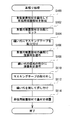
- FIG. 2 is a flowchart of the leather processing of this embodiment.
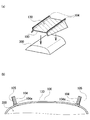
- FIG. 3A is a perspective view of the leather covering member of the present embodiment formed by overlapping and sewing the end portions of the leather element member
- FIG. 3B is a perspective view of FIG. It is a fragmentary perspective view which shows the state which expanded the leather element member of the covering member for leather tension.
- FIG. 1A is a perspective view showing an example of a vehicle interior part of the embodiment of the present disclosure mounted in a vehicle interior of the vehicle
- FIG. 1B is a vehicle interior of the embodiment of the present disclosure. It is a disassembled perspective view which shows the structure of the armrest of Fig.1 (a
- FIG. 4A is a perspective view showing a process of setting the leather covering member of this embodiment on a jig
- FIG. 4B is a leather tension set on the jig of FIG. It is an expanded partial sectional view which shows the coating
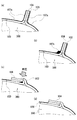
- FIG. 5A to FIG. 5D are explanatory diagrams showing a process of making the seam allowance collapsed.
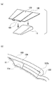
- FIG. 6A is a perspective view showing a process of attaching the leather covering member to the base material
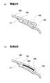
- FIG. 6B shows the leather covering member attached to the base material of FIG. It is an expanded partial sectional view shown.
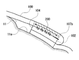
- FIG. 7A is an explanatory view showing a leather covering member in which the seam allowance is lowered by a method different from that of the present embodiment, and FIG. 7B is still another example different from the present embodiment. It is explanatory drawing which shows the covering member for leather tension made into the state which fell the seam allowance by the method.
- FIG. 8 is an explanatory diagram conceptually showing the effect of this embodiment.
- FIG. 1A shows a general interior of a vehicle.
- Various interior parts for vehicles are mounted in the passenger compartment, and some of these are leather-finished for decoration and the like.
- the interior parts for a vehicle to which the leather treatment is applied include an armrest provided on the seat and a palm for the driver to operate the vehicle input device. Examples thereof include a palm rest, a cover that covers the dashboard, and the like.
- the armrest 10 as an example from these, the procedure for performing the leather tension processing will be described.
- FIG. 1 (b) it becomes a main body part of the armrest 10 of the present embodiment, and a base material 11 to be subjected to leather processing and three small leather members (leather element members) 100a, 100b, 100c.
- the base material 11 is formed in the shape of the armrest 10 using resin.
- the leather element member 100 a is formed in a rectangular shape corresponding to the upper surface portion of the base material 11, and the leather element member 100 b and the leather element member 100 c are each a base corresponding to the side surface portion of the base material 11. It is formed into a shape.
- the leather element members 100a to 100c include a seam allowance.
- the armrest 10 is produced by performing a leather tensioning process in which the leather element members 100a to 100c are attached to the base material 11.
- FIG. 2 shows a flowchart of the leather processing of this embodiment.
- the leather covering member is formed by stitching the three leather element members 100a to 100c (S100).
- the leather element member 100a corresponds to the upper surface of the base material 11
- the leather element member 100b and the leather element member 100c correspond to the side surfaces of the base material 11, respectively. Then, the leather element member 100b and the leather element member 100c are stitched along both sides of the leather element member 100a.
- FIG. 3A shows a state in which the leather element member 100b and the leather element member 100c are stitched to the leather element member 100a.
- the stitching of the leather element member 100a and the leather element member 100b is performed at the sewing margin 104 provided at the end portion of the leather element member 100a and the end portion of the leather element member 100b by aligning the front sides of the leather.
- the obtained seam allowance 104 is sewn together.
- the stitching of the leather element member 100a and the leather element member 100c is performed by combining the leather front sides with the seam allowance 104 at the end of the leather element member 100a and the end of the leather element member 100c.
- the seam allowance 104 is sewn together.
- the seam 102 is formed at the position of the root 104a of the seam allowance 104 where the two leather element members (100a and 100b, 100a and 100c) are sewn (see FIG. 3A). Therefore, when the leather element member 100b and the leather element member 100c are expanded with respect to the leather element member 100a, the leather element members 100a to 100c are bent at the seam 102, and the leather element members 100a to 100c are folded. On the back side, the seam allowance 104 protrudes (see FIG. 3B). Although the protruding seam allowance 104 is not visible from the front side of the leather element members 100 a to 100 c, it interferes when the leather element members 100 a to 100 c are attached to the base material 11. Therefore, in the leather tension processing of the present embodiment, the seam allowance 104 is brought into a fallen state as follows.
- the stitched leather element members 100a to 100c are collectively referred to as a leather covering member (or covering member) 100.
- the leather covering member 100 is cured with the back side 130 of the leather covering member 100 facing upward, that is, with the seam allowance 104 protruding upward. It is set on the tool 300 (S102).
- a pedestal having an upper surface comparable to the size of the leather covering member 100 is used as the jig 300.
- the adhesive 107a is applied to the entire back side 130 of the leather covering member 100 (S106).
- the adhesive 107 a is used to adhere the leather covering member 100 to the base material 11.
- the adhesive 107 a is uniformly applied to the back side 130 of the leather covering member 100 by spraying the adhesive 107 a using a spray.
- FIG. 5A shows a state in which the adhesive 107 a is applied to the entire back side 130 of the leather covering member 100.
- the adhesive 107a is applied from above the masking tape 105 to the portion where the masking tape 105 is attached.
- the adhesive 107a When the adhesive 107a is applied to the entire back side 130 of the leather covering member 100 (S106 in FIG. 2), the adhesive 107b is applied to the root 104a of the seam allowance 104 (S108). This adhesive 107b is for making the seam allowance 104 fall. In other words, as described above with reference to FIG. 3B, the seam allowance 104 is collapsed because it interferes when the leather covering member 100 is stuck to the base material 11 with the seam allowance 104 protruding.
- An adhesive hereinafter referred to as “sewing substitute adhesive”) 107b for applying a state is applied.
- FIG. 5B shows a state in which the sewing substitute adhesive 107b is applied to the root 104a of the sewing allowance 104 (see FIG. 4B).
- the seam substitute adhesive 107b is applied to the base 104a of the side surface of the seam allowance 104 where the masking tape 105 is not attached, over the longitudinal direction of the seam allowance 104.
- the seam substitute adhesive 107b is applied to the base 104a of the seam allowance 104 (S108 in FIG. 2), the masking tape 105 attached in the process of S104 is removed (S110). Then, by pressing the side surface from which the masking tape 105 of the seam allowance 104 has been removed, that is, the side surface from which the adhesive 107a has been removed, the seam allowance 104 is brought into a state of being tilted with the seam 102 as a boundary (S112).
- FIG. 5 (c) shows a state in which the seam allowance 104 is tilted to the side surface (left side in the figure) to which the seam surrogate adhesive 107b has been applied.
- the base 104a of the seam allowance 104 is adhered to the back side 130 of the leather covering member 100 by the seam surrogate adhesive 107b, and the seam allowance 104 is maintained in the collapsed state. (See FIG. 5 (d)).
- the adhesive 107a is removed by removing the masking tape 105 from the side surface that is pressed when the seam allowance 104 is brought into a collapsed state, the hands and rollers may adhere to the seam allowance 104. Can be suppressed.
- the adhesive 107a is applied to the entire back side 130 of the leather covering member 100 (S106 in FIG. 2), the sewing substitute adhesive 107b is applied to the root 104a of the sewing allowance 104 (S108).
- any of the processes for applying the adhesives 107a and 107b may be performed first.
- FIG. 6A shows a state in which the leather covering member 100 is attached to the base material 11.
- the leather covering member 100 is pasted on the base material 11 without the seam allowance 104 interfering. It becomes possible to attach.
- a recess 11a for accommodating the seam allowance 104 is formed at a position corresponding to the seam allowance 104 of the base material 11 by recessing the surface. If it carries out like this, the front side 120 of the leather covering member 100 will not be lifted by the seam allowance 104, and the front side 120 can be made flatter.
- the leather covering member 100 when the leather covering member 100 is affixed to the base material 11, the leather covering member 100 is positioned with respect to the base material 11 by accommodating the seam allowance 104 on the back surface 130 side in the recess 11 a. Therefore, the work of attaching the leather becomes even easier.
- the portion facing the seam allowance 104 of the leather covering member 100 (the portion with rough hatching in the drawing, the following A method of adhering the seam allowance 104 with the double-sided tape 109 is also conceivable.
- the double-sided tape 109 is less flexible than the facing part 200, the flexibility of the facing part 200 is limited by the double-sided tape 109.
- the facing portion 200 is fixed to the seam allowance 104 by the double-sided tape 109, the amount of movement of the facing portion 200 relative to the seam allowance 104 is also limited. As a result, when leather is applied, wrinkles are generated around the facing portion 200 and the aesthetic appearance is impaired.
- the seam allowance 104 was collapsed using only the adhesive by applying the seam surrogate adhesive 107b to the base 104a of the seam allowance 104 and defeating the seam allowance 104. Since it can be put into a state, it does not take time and is excellent in workability. Further, since the base 104a of the seam allowance 104 is bonded, as shown in FIG. 8, it is possible to suppress the vicinity of the base 104a of the seam allowance 104 from being floated, and it is possible to improve the aesthetic appearance.
- the seam substitute adhesive 107b is bonded to the root 104a of the seam allowance 104, as shown by the solid line arrow in FIG. Further, as shown by a broken line arrow in FIG. 8, the movement amount of the facing portion 200 relative to the seam allowance 104 can also be suppressed. As a result, it is possible to suppress the generation of wrinkles around the facing portion 200 and improve the aesthetic appearance.
- the above-described flexibility can be further enhanced and the above-described movement amount can be secured more. And the aesthetics can be further improved.
- the seam substitute adhesive 107b is applied to the base 104a portion of the seam allowance 104 in order to bond the base 104a portion of the seam allowance 104.
- the sewing substitute adhesive 107 b is applied in such a manner as to adhere to the root 104 a of the sewing allowance 104 when the sewing allowance 104 is tilted.
- the sewing substitute adhesive 107b may be applied to a position slightly apart from the root 104a of the seam allowance 104, and the seam substitute adhesive 107b may enter the root 104a of the seam allowance 104 when the seam allowance 104 is tilted.
- the effects as described above can be obtained.
Landscapes
- Engineering & Computer Science (AREA)
- Mechanical Engineering (AREA)
- Vehicle Interior And Exterior Ornaments, Soundproofing, And Insulation (AREA)
- Lining Or Joining Of Plastics Or The Like (AREA)
Abstract
複数枚の要素部材(100a、100b、100c)を、縫い代(104)が同じ側を向くように向かい合わせた状態で、縫い代(104)の根元(104a)同士を縫合することによって被覆部材(100)を形成する。そして、縫合された縫い代(104)の何れか一方の縫い代(104)には、少なくとも根元(104a)の部分に接着剤(107b)を塗布して、その根元(104a)の部分を内側にして、その一方の縫い代(104)を他方の縫い代(104)と共に折り返す。その後、縫い代(104)が折り返された被覆部材(100)を、基材(11)の上に被覆する。
Description
本願は、2013年6月28日に出願された日本国特許出願第2013-137117号に基づくものであり、この開示をもってその内容を本明細書中に開示したものとする。
本開示は、車両の車室内に装着されて、車室内に面する表面の少なくとも一部が被覆された車両用内装部品と、該車両用内装部品の製造方法とに関する。
車両の車室内には、小物を収納するためのグローブボックスカバーや、運転者が肘掛けとして用いるアームレスト、運転者が車両用入力機器を操作するために手のひらを置くパームレストなど、様々な内装部品が搭載されている。これらの車両用内装部品は、今日では主に硬質樹脂材料によって形成されることが通常であるが、高級感を出すために、車両用内装部品の少なくとも一部の表面を、革や織布あるいは帆布などのように柔軟で高級感のあるシート状の別部材で被覆することがある。
これら車両用内装部品の被覆は、次のようにして行われる。先ず、硬質樹脂などで形成された被覆しようとする部材(以下、「基材」と呼ぶ)の形状に合わせて、シート状の部材を裁断することによって複数枚の小さな部材(以下、「要素部材」と呼ぶ)を用意し、それら要素部材を、表側同士が向かい合わせとなるように重ねて、被覆部材の端部を縫い合わせる。
その後、縫い合わせていない部分から要素部材を裏返して広げると、所望の3次元的な形状に縫合された被覆部材ができあがる。このときの要素部材を縫い合わせた縫い目は「インステッチ」と呼ばれる。また、要素部材が縫い合わされた部分の裏側には、2枚の要素部材の端部が向かい合わせになった部分(以下、「縫い代」と呼ぶ)が形成されるが、被覆部材の表側からは見えることはない。
続いて、要素部材が縫い合わされた被覆部材の裏側に接着剤を塗布した後、基材に被せて接着剤を硬化させることによって、被覆部材と基材とを接着する。このとき、縫い代を立たせたままにしておくと、被覆部材を基材に被せる作業の邪魔になる。
そこで、被覆部材を基材に被せる前に、縫い代を、縫い目(インステッチ)の部分でどちらか一方に倒した状態で、倒した方の被覆部材(実際には要素部材)に縫い代を縫い付けておく(特許文献1)。尚、倒した縫い代を被覆部材に縫い付けるための縫い目は、「アウトステッチ」と呼ばれる。
しかし、上述した従来から用いられている方法では、裁断した要素部材をインステッチで縫い合わせた後、更にアウトステッチで縫い代を被覆部材に縫い付ける必要があるため、車両用内装部品の製造に手間が掛かるという問題があった。
本開示は、上述した問題に鑑みてなされたものであり、本開示の目的は、製造が容易であって、表面の少なくとも一部が被覆部材で被覆された車両用内装部品を提供することにある。本開示の別の目的は、前記車両用内装部品の製造方法を提供することにある。
上記の目的を達成するために、本開示では、車両の車室内に装着されて、該車室内に面する表面の少なくとも一部が被覆された車両用内装部品を提供する。前記車両用内装部品は、シート状の複数の要素部材を有し、前記複数の要素部材が縫合によって繋ぎ合わされて、前記車両用内装部品の前記表面の少なくとも一部を被覆する被覆部材と、前記被覆部材が被覆される基材とを備える。前記被覆部材は、前記複数の要素部材の1つの端部に設けられた縫い代と、前記複数の要素部材の別の1つの端部に設けられた縫い代とが、前記基材の側に来るように向かい合わされた状態で、該縫い代の根元で縫合されており、前記縫合された縫い代の一方が前記根元の部分で折り返され、該折り返された縫い代に他方の前記縫い代が重ねられていると共に、該折り返された縫い代の少なくとも根元の部分に接着剤が塗布された被覆部材である。
また、上記の目的を達成するために、本開示では、車両の車室内に装着されて、該車室内に面する表面の少なくとも一部が被覆された車両用内装部品の製造方法を提供する。前記製造方法は、端部に縫合のための縫い代が設けられたシート状の複数の要素部材を、該縫い代が同じ側を向くように向かい合わせた状態で該縫い代の根元同士を縫合することにより、前記複数の要素部材が繋ぎ合わされた被覆部材を形成する第1の工程と、前記縫合された縫い代の何れか一方の少なくとも前記根元の部分に接着剤を塗布した後、該接着剤を塗布した該根元の部分を内側にして、該接着剤が塗布された一方の縫い代を他方の縫い代と共に折り返す第2の工程と、前記縫い代が折り返された前記被覆部材を、前記車両用内装部品の基材の上に被覆する第3の工程とを備える。
こうすれば、一方の縫い代の根元の部分に塗布した接着剤によって、その一方の縫い代が折り返された状態に維持される。そして、他方の縫い代は折り返された縫い代に重なった状態となるので、縫合された縫い代の部分が倒れた状態となる。このため、縫い代を倒した状態とするために、アウトステッチで縫い付ける必要が無くなるので、車両用内装部品を簡単に製造することが可能となる。
また、上述した本開示の車両用内装部品においては、被覆部材の縫い代を収納する凹部を基材に設けることとしても良い。
こうすれば、被覆部材の縫い代が基材の凹部に収納されるので、縫い代の部分で被覆部材の表面が盛り上がることを抑制できる。また、縫い代が基材の凹部に収納される結果、基材に対して被覆部材が位置決めされるので、基材に被覆部材を被覆する作業を容易化することができる。
また、上述した本開示の車両用内装部品の製造方法においては、縫い代の根元の部分に塗布された接着剤の固化が終了する前に、被覆部材を基材の上に被覆することとしてもよい。
こうすれば、縫い代の根元の部分に塗布された接着剤が、縫い代を折り返した際に根元以外の部分に広がったとしても、折り返した縫い代が貼り付いて被覆部材の表面側(車室内に面する側)が突っ張ってしまうことがない。このため、表面に皺を生じさせることなく、基材に被覆部材を被覆することが可能となる。
以下では、上述した本願の開示の内容を明確にするために実施例について説明する。図1(a)には、一般的な車両の車室内の様子が示されている。車室内には種々の車両用内装部品が搭載されており、これらの中には、装飾などを目的として革張り処理が施されているものがある。革張り処理が施された車両用内装部品としては、図1(a)中にハッチングで示すように、座席に設けられた肘掛けや、運転者が車両用入力機器を操作するために手のひらを置くパームレスト、ダッシュボードを覆うカバー等を例示することができる。以下では、これらの中から肘掛け10を例にとって、革張り処理を施す手順について説明する。
図1(b)には、本実施例の肘掛け10の本体部分となり、革張り処理が施される基材11と、3枚の革製の小さな部材(革製要素部材)100a,100b,100cとが示されている。基材11は、樹脂を用いて肘掛け10の形状に形成されている。また、革製要素部材100aは、基材11の上面部分に対応して長方形状に形成され、革製要素部材100bおよび革製要素部材100cは、それぞれ基材11の側面部分に対応して台形状に形成されている。また、革製要素部材100a~100cには縫い代が含まれている。そして、肘掛け10は、基材11に革製要素部材100a~100cを貼り付ける革張り処理が施されることによって制作される。
図2には、本実施例の革張り処理のフローチャートが示されている。本実施例の革張り処理では、先ず始めに、3枚の革製要素部材100a~100cを縫合することによって革張用被覆部材を形成する(S100)。
前述したように、革製要素部材100aは基材11の上面に対応し、革製要素部材100bおよび革製要素部材100cは、それぞれ基材11の側面に対応することから、このS100の処理では、革製要素部材100aの両側辺に沿って、革製要素部材100bおよび革製要素部材100cを縫合する。
図3(a)には、革製要素部材100aに対して、革製要素部材100bおよび革製要素部材100cが縫合された様子が示されている。革製要素部材100aと革製要素部材100bとの縫合は、革の表側同士を合わせて、革製要素部材100aの端部に設けられた縫い代104と、革製要素部材100bの端部に設けられた縫い代104とを縫い合わせる。また、革製要素部材100aと革製要素部材100cとの縫合も同様に、革の表側同士を合わせて、革製要素部材100aの端部の縫い代104と、革製要素部材100cの端部の縫い代104とを縫い合わせる。
この結果、2枚の革製要素部材(100aと100b、100aと100c)が縫合された縫い代104の根元104aの位置には、縫い目102が形成される(図3(a)参照)。このため、革製要素部材100aに対して革製要素部材100bおよび革製要素部材100cを広げると、縫い目102を境に革製要素部材100a~100cが折り曲げられて、革製要素部材100a~100cの裏側では、縫い代104が突出した状態となる(図3(b)参照)。この突出した縫い代104は、革製要素部材100a~100cの表側からは視認されないものの、革製要素部材100a~100cを基材11に張り付ける際に邪魔になる。そこで、本実施例の革張り処理では、次のようにして縫い代104を倒れた状態にする。尚、以下では、縫合された革製要素部材100a~100cを、まとめて革張用被覆部材(または被覆部材)100と称する。
先ず、図4(a)に示されるように、革張用被覆部材100の裏側130を上方に向けた状態、すなわち、縫い代104を上方に突出させた状態で、革張用被覆部材100を治具300の上にセットする(S102)。本実施例では、革張用被覆部材100の大きさと同程度の上面を有する台座が、治具300として利用される。
図4(b)には、治具300に載せられた革張用被覆部材100の断面図が示されている。革張用被覆部材100を治具300の上に載せたら(S102)、図4(b)に示すように、2つの縫い代104の一側面にマスキングテープ105を貼り付ける(S104)。後述するように、本実施例の革貼り処理では、縫い代104の一側面を手やローラー等で押圧することで該縫い代104を倒れた状態とするが、S104の処理では、手やローラー等で押圧されることとなる側面にマスキングテープ105を貼り付ける。
こうして縫い代104の一側面にマスキングテープ105を貼り付けたら(図2のS104)、革張用被覆部材100の裏側130の全体に接着剤107aを塗布する(S106)。この接着剤107aは、革張用被覆部材100を基材11に接着させるためのものである。ここでは、スプレーを用いて接着剤107aを噴霧することで、革張用被覆部材100の裏側130に均一に接着剤107aを塗布する。図5(a)には、革張用被覆部材100の裏側130の全体に接着剤107aが塗布された様子が示されている。もちろん、マスキングテープ105が貼り付けられた部分には、マスキングテープ105の上から接着剤107aが塗布されることとなる。
革張用被覆部材100の裏側130の全体に接着剤107aを塗布したら(図2のS106)、縫い代104の根元104aに接着剤107bを塗布する(S108)。この接着剤107bは、縫い代104を倒れた状態にするためのものである。つまり、図3(b)を用いて前述したように、縫い代104が突出した状態のままでは、革張用被覆部材100を基材11に張り付ける際に邪魔になるので、縫い代104を倒れた状態にするための接着剤(以下では「縫い代用接着剤」という)107bを塗布する。
図5(b)には、縫い代104の根元104a(図4(b)参照)に縫い代用接着剤107bが塗布された様子が示されている。図示されるように、縫い代用接着剤107bは、縫い代104の両側面のうち、マスキングテープ105が貼り付けられていない方の側面の根元104aに、縫い代104の長手方向に亘って塗布される。
こうして、縫い代104の根元104aに縫い代用接着剤107bを塗布したら(図2のS108)、S104の処理で貼り付けたマスキングテープ105を取り外す(S110)。そして、縫い代104のマスキングテープ105が取り外された側面、すなわち、接着剤107aが取り除かれた側面を押圧することで、縫い目102を境に縫い代104を倒した状態にする(S112)。
図5(c)には、縫い代104を縫い代用接着剤107bが塗布された側面側(図中、左側)へ倒した様子が示されている。このように縫い代104を倒した状態とすることで、縫い代104の根元104aが縫い代用接着剤107bによって革張用被覆部材100の裏側130に接着されて、縫い代104が倒れた状態に維持される(図5(d)参照)。
尚、上述したように、縫い代104を倒れた状態とする際に押圧される側面からはマスキングテープ105を取り外すことによって接着剤107aが取り除かれるので、手やローラーが縫い代104に接着してしまうことを抑制できる。また、上述した説明では、革張用被覆部材100の裏側130の全体に接着剤107aを塗布した後(図2のS106)、縫い代104の根元104aに縫い代用接着剤107bを塗布する(S108)ものとして説明した。しかし、これらの接着剤107a、107bを塗布する処理は、何れの処理を先に行ってもよい。
こうして縫い代104を倒れた状態にしたら(S112)、革張用被覆部材100を伸ばしながら(裏側130を)基材11に張り付ける(S114)。図6(a)には、革張用被覆部材100を基材11に張り付ける様子が示されている。図示されるように、革張用被覆部材100の裏側130に形成された縫い代104は倒れた状態であることから、縫い代104が邪魔になることなく基材11に革張用被覆部材100を貼り付けることが可能となる。
また、図6(b)に示すように、基材11の縫い代104に対応する位置には、該縫い代104を収容する凹部11aが、表面を窪ませることにより形成されている。こうすると、革張用被覆部材100の表側120が縫い代104によって持ち上げられることがなく、表側120をより平坦にすることができる。
加えて、革張用被覆部材100を基材11に貼り付ける際に、裏面130側の縫い代104が凹部11aに収容されることによって、基材11に対して革張用被覆部材100が位置決めされるので、革張りする作業がより一層容易となる。
もっとも、縫い代104を倒れた状態にするのであれば、図7(a)に示すように、縫い代104を倒した状態で革張用被覆部材100に縫い付けておく方法も考えられる。しかし、この場合は、上述した縫合処理(図2のS100、縫い目102)を行った上に、縫い代104を倒れた状態とするための縫合(図中、縫い目106。いわゆるアウトステッチ)をすることになるので手間が掛かってしまう。また、この縫合は縫い代104を倒しながら行うので、縫い目102と縫い目106との距離が大きくなりがちであり、図示されるように、縫い目106の位置から縫い代104の根元104aにかけて浮いた状態になり、美観が損なわれてしまう。
また、縫い代104を倒れた状態にする別の方法として、図7(b)に示すように、革張用被覆部材100の縫い代104に対向する部分(図中で粗いハッチングを施した部分、以下「対向部200」という)と、縫い代104とを両面テープ109で接着する方法も考えられる。しかし、両面テープ109は対向部200と比較して柔軟性が低いので、対向部200の柔軟性が両面テープ109によって制限されてしまう。さらに、対向部200は両面テープ109によって縫い代104に固定されるので、縫い代104に対する対向部200の移動量も制限されてしまう。これらの結果、革張りをする際に対向部200の周辺に皺が生じて、美観が損なわれてしまう。
これらの方法に対して、本実施例の革張り処理は、縫い代104の根元104aに縫い代用接着剤107bを塗布して縫い代104を倒すことで、接着剤のみを使用して縫い代104を倒れた状態にすることができるので、手間が掛からず作業性に優れる。また、縫い代104の根元104aを接着するので、図8に示すように、縫い代104の根元104a付近が浮いた状態になることを抑制することができ、美観を向上させることが可能となる。
また、縫い代用接着剤107bは縫い代104の根元104aに接着されるので、図8に実線の矢印で示すように、対向部200の柔軟性が制限されることを抑制することができる。また、図8に破線の矢印で示すように、縫い代104に対する対向部200の移動量が制限されることも抑制することができる。これらの結果、対向部200の周辺に皺が生じることを抑制して、美観を向上させることが可能となる。
さらに、縫い代用接着剤107bの固化が終了する前に(いわゆる生乾きの状態で)革張り処理を施すことで、上述の柔軟性をさらに高めることができるとともに、上述の移動量をより多く確保することができ、更に美観を向上させることが可能となる。
以上では、縫い代104の根元104aの部分を接着させるために、縫い代用接着剤107bが縫い代104の根元104aの部分に塗布されるものとして説明した。しかし、縫い代用接着剤107bは、必ずしも縫い代104の根元104aの部分に直接塗布する必要はない。縫い代104を倒した際に、縫い代用接着剤107bが縫い代104の根元104aに付着する態様で塗布されていればよい。例えば、縫い代104の根元104aから少し離れた位置に縫い代用接着剤107bを塗布し、縫い代104を倒した際に縫い代用接着剤107bが縫い代104の根元104aに入り込む態様であればよい。もちろん、このような場合であっても、上述したような効果を得ることができる。
Claims (4)
- 車両の車室内に装着されて、該車室内に面する表面の少なくとも一部が被覆された車両用内装部品であって、
シート状の複数の要素部材(100a、100b、100c)を有し、前記複数の要素部材(100a、100b、100c)が縫合によって繋ぎ合わされて、前記車両用内装部品の前記表面の少なくとも一部を被覆する被覆部材(100)と、
前記被覆部材(100)が被覆される基材(11)と
を備え、
前記被覆部材(100)は、
前記複数の要素部材(100a、100b、100c)の1つの端部に設けられた縫い代(104)と、前記複数の要素部材(100a、100b、100c)の別の1つの端部に設けられた縫い代(104)とが、前記基材(11)の側に来るように向かい合わされた状態で、該縫い代(104)の根元(104a)で縫合されており、
前記縫合された縫い代(104)の一方が前記根元(104a)の部分で折り返され、該折り返された縫い代(104)に他方の前記縫い代(104)が重ねられていると共に、該折り返された縫い代(104)の少なくとも根元(104a)の部分に接着剤(107b)が塗布された被覆部材である
車両用内装部品。 - 請求項1に記載の車両用内装部品であって、
前記基材(11)には、前記被覆部材(100)の前記縫い代(104)を収納する凹部(11a)が形成されている
車両用内装部品。 - 車両の車室内に装着されて、該車室内に面する表面の少なくとも一部が被覆された車両用内装部品の製造方法であって、
端部に縫合のための縫い代(104)が設けられたシート状の複数の要素部材(100a、100b、100c)を、該縫い代(104)が同じ側を向くように向かい合わせた状態で該縫い代(104)の根元(104a)同士を縫合することにより、前記複数の要素部材(100a、100b、100c)が繋ぎ合わされた被覆部材(100)を形成する第1の工程と、
前記縫合された縫い代(104)の何れか一方の少なくとも前記根元(104a)の部分に接着剤(107b)を塗布した後、該接着剤(107b)を塗布した該根元(104a)の部分を内側にして、該接着剤(107b)が塗布された一方の縫い代(104)を他方の縫い代(104)と共に折り返す第2の工程と、
前記縫い代(104)が折り返された前記被覆部材(100)を、前記車両用内装部品の基材(11)の上に被覆する第3の工程と
を備える製造方法。 - 請求項3に記載の製造方法であって、
前記第3の工程は、前記縫い代(104)の前記根元(104a)の部分に塗布された前記接着剤(107b)の固化が終了する前に、前記被覆部材(100)を前記基材(11)の上に被覆する工程である
製造方法。
Applications Claiming Priority (2)
| Application Number | Priority Date | Filing Date | Title |
|---|---|---|---|
| JP2013137117A JP2015009693A (ja) | 2013-06-28 | 2013-06-28 | 車両用内装部品、および車両用内装部品の製造方法 |
| JP2013-137117 | 2013-06-28 |
Publications (1)
| Publication Number | Publication Date |
|---|---|
| WO2014208079A1 true WO2014208079A1 (ja) | 2014-12-31 |
Family
ID=52141438
Family Applications (1)
| Application Number | Title | Priority Date | Filing Date |
|---|---|---|---|
| PCT/JP2014/003375 Ceased WO2014208079A1 (ja) | 2013-06-28 | 2014-06-24 | 車両用内装部品、および車両用内装部品の製造方法 |
Country Status (2)
| Country | Link |
|---|---|
| JP (1) | JP2015009693A (ja) |
| WO (1) | WO2014208079A1 (ja) |
Cited By (2)
| Publication number | Priority date | Publication date | Assignee | Title |
|---|---|---|---|---|
| CN115142203A (zh) * | 2021-03-31 | 2022-10-04 | 利萨·德雷克塞迈尔有限责任公司 | 用于连接预备护套元件的方法、预备机以及用于将两个护套元件连接起来的方法 |
| JP2024039481A (ja) * | 2022-09-09 | 2024-03-22 | 日本プラスト株式会社 | 表皮部材及び内装部材 |
Citations (2)
| Publication number | Priority date | Publication date | Assignee | Title |
|---|---|---|---|---|
| JP2003212057A (ja) * | 2002-01-22 | 2003-07-30 | Inoac Corp | 車両内装部材 |
| JP2004026084A (ja) * | 2002-06-27 | 2004-01-29 | Toyoda Gosei Co Ltd | 皮巻きステアリングホイール |
-
2013
- 2013-06-28 JP JP2013137117A patent/JP2015009693A/ja active Pending
-
2014
- 2014-06-24 WO PCT/JP2014/003375 patent/WO2014208079A1/ja not_active Ceased
Patent Citations (2)
| Publication number | Priority date | Publication date | Assignee | Title |
|---|---|---|---|---|
| JP2003212057A (ja) * | 2002-01-22 | 2003-07-30 | Inoac Corp | 車両内装部材 |
| JP2004026084A (ja) * | 2002-06-27 | 2004-01-29 | Toyoda Gosei Co Ltd | 皮巻きステアリングホイール |
Cited By (4)
| Publication number | Priority date | Publication date | Assignee | Title |
|---|---|---|---|---|
| CN115142203A (zh) * | 2021-03-31 | 2022-10-04 | 利萨·德雷克塞迈尔有限责任公司 | 用于连接预备护套元件的方法、预备机以及用于将两个护套元件连接起来的方法 |
| CN115142203B (zh) * | 2021-03-31 | 2024-08-20 | 利萨·德雷克塞迈尔有限责任公司 | 用于连接预备护套元件的方法、预备机以及用于将两个护套元件彼此连接的方法和连接工具 |
| JP2024039481A (ja) * | 2022-09-09 | 2024-03-22 | 日本プラスト株式会社 | 表皮部材及び内装部材 |
| JP7832083B2 (ja) | 2022-09-09 | 2026-03-17 | 日本プラスト株式会社 | 表皮部材及び内装部材 |
Also Published As
| Publication number | Publication date |
|---|---|
| JP2015009693A (ja) | 2015-01-19 |
Similar Documents
| Publication | Publication Date | Title |
|---|---|---|
| CN104053577A (zh) | 用于与车辆内部部件的装饰线迹一起使用的线缝间隔部件 | |
| CN107531193B (zh) | 缝制覆盖物、包括载体部件和缝制覆盖物的组件 | |
| KR101773138B1 (ko) | 차량용 내장재 제조방법 | |
| US20100193108A1 (en) | Manufacturing method of a vehicular interior part | |
| US20110171435A1 (en) | Single side stitching for interior skins | |
| US20050000622A1 (en) | Method of producing garment blanks having seamless trim | |
| WO2014208079A1 (ja) | 車両用内装部品、および車両用内装部品の製造方法 | |
| JP5468518B2 (ja) | 車両内装部材 | |
| CN106965723B (zh) | 车辆用座椅的装饰罩的缝制处理方法及车辆用座椅 | |
| JP7059152B2 (ja) | 自動車の内装部品の製造方法 | |
| JP6440460B2 (ja) | 車両用内装部品 | |
| JP5944163B2 (ja) | 自動車内装品及びその製造方法 | |
| JP7013328B2 (ja) | シート | |
| JP6144856B1 (ja) | 通気口とその作成方法 | |
| JPH0736559Y2 (ja) | シートカバー | |
| JP7779730B2 (ja) | 内装部材、および、内装部材の製造方法。 | |
| TW201404326A (zh) | 免縫鞋面的製造方法 | |
| JP7832083B2 (ja) | 表皮部材及び内装部材 | |
| JP2012090677A (ja) | シートカバー | |
| JP6231402B2 (ja) | 装飾部材 | |
| US20070199644A1 (en) | Method of covering an automobile shift knob with leather | |
| KR20170112350A (ko) | 차량용 내장부품의 표피재 압착 장치 및 그의 압착방법 | |
| JPH11115492A (ja) | 自動車ドアライニングのセンターパッド | |
| JP7695752B1 (ja) | 表皮付き製品の製造方法 | |
| JP2016034774A (ja) | 車両の内装部品の製造方法 |
Legal Events
| Date | Code | Title | Description |
|---|---|---|---|
| 121 | Ep: the epo has been informed by wipo that ep was designated in this application |
Ref document number: 14817567 Country of ref document: EP Kind code of ref document: A1 |
|
| NENP | Non-entry into the national phase |
Ref country code: DE |
|
| 122 | Ep: pct application non-entry in european phase |
Ref document number: 14817567 Country of ref document: EP Kind code of ref document: A1 |