WO2014196541A1 - レーダ装置、その軸ズレ検査方法、及びプログラムを記録したコンピュータ読み取り可能な記録媒体 - Google Patents
レーダ装置、その軸ズレ検査方法、及びプログラムを記録したコンピュータ読み取り可能な記録媒体 Download PDFInfo
- Publication number
- WO2014196541A1 WO2014196541A1 PCT/JP2014/064769 JP2014064769W WO2014196541A1 WO 2014196541 A1 WO2014196541 A1 WO 2014196541A1 JP 2014064769 W JP2014064769 W JP 2014064769W WO 2014196541 A1 WO2014196541 A1 WO 2014196541A1
- Authority
- WO
- WIPO (PCT)
- Prior art keywords
- intensity
- frequency
- radar
- reflection intensity
- wave
- Prior art date
- Legal status (The legal status is an assumption and is not a legal conclusion. Google has not performed a legal analysis and makes no representation as to the accuracy of the status listed.)
- Ceased
Links
Images






Classifications
-
- G—PHYSICS
- G01—MEASURING; TESTING
- G01S—RADIO DIRECTION-FINDING; RADIO NAVIGATION; DETERMINING DISTANCE OR VELOCITY BY USE OF RADIO WAVES; LOCATING OR PRESENCE-DETECTING BY USE OF THE REFLECTION OR RERADIATION OF RADIO WAVES; ANALOGOUS ARRANGEMENTS USING OTHER WAVES
- G01S7/00—Details of systems according to groups G01S13/00, G01S15/00, G01S17/00
- G01S7/02—Details of systems according to groups G01S13/00, G01S15/00, G01S17/00 of systems according to group G01S13/00
- G01S7/40—Means for monitoring or calibrating
- G01S7/4004—Means for monitoring or calibrating of parts of a radar system
- G01S7/4026—Antenna boresight
- G01S7/4034—Antenna boresight in elevation, i.e. in the vertical plane
-
- G—PHYSICS
- G01—MEASURING; TESTING
- G01S—RADIO DIRECTION-FINDING; RADIO NAVIGATION; DETERMINING DISTANCE OR VELOCITY BY USE OF RADIO WAVES; LOCATING OR PRESENCE-DETECTING BY USE OF THE REFLECTION OR RERADIATION OF RADIO WAVES; ANALOGOUS ARRANGEMENTS USING OTHER WAVES
- G01S7/00—Details of systems according to groups G01S13/00, G01S15/00, G01S17/00
- G01S7/02—Details of systems according to groups G01S13/00, G01S15/00, G01S17/00 of systems according to group G01S13/00
- G01S7/40—Means for monitoring or calibrating
- G01S7/4004—Means for monitoring or calibrating of parts of a radar system
- G01S7/4026—Antenna boresight
-
- G—PHYSICS
- G01—MEASURING; TESTING
- G01S—RADIO DIRECTION-FINDING; RADIO NAVIGATION; DETERMINING DISTANCE OR VELOCITY BY USE OF RADIO WAVES; LOCATING OR PRESENCE-DETECTING BY USE OF THE REFLECTION OR RERADIATION OF RADIO WAVES; ANALOGOUS ARRANGEMENTS USING OTHER WAVES
- G01S13/00—Systems using the reflection or reradiation of radio waves, e.g. radar systems; Analogous systems using reflection or reradiation of waves whose nature or wavelength is irrelevant or unspecified
- G01S13/02—Systems using reflection of radio waves, e.g. primary radar systems; Analogous systems
- G01S13/06—Systems determining position data of a target
- G01S13/08—Systems for measuring distance only
- G01S13/32—Systems for measuring distance only using transmission of continuous waves, whether amplitude-, frequency-, or phase-modulated, or unmodulated
- G01S13/34—Systems for measuring distance only using transmission of continuous waves, whether amplitude-, frequency-, or phase-modulated, or unmodulated using transmission of continuous, frequency-modulated waves while heterodyning the received signal, or a signal derived therefrom, with a locally-generated signal related to the contemporaneously transmitted signal
-
- G—PHYSICS
- G01—MEASURING; TESTING
- G01S—RADIO DIRECTION-FINDING; RADIO NAVIGATION; DETERMINING DISTANCE OR VELOCITY BY USE OF RADIO WAVES; LOCATING OR PRESENCE-DETECTING BY USE OF THE REFLECTION OR RERADIATION OF RADIO WAVES; ANALOGOUS ARRANGEMENTS USING OTHER WAVES
- G01S13/00—Systems using the reflection or reradiation of radio waves, e.g. radar systems; Analogous systems using reflection or reradiation of waves whose nature or wavelength is irrelevant or unspecified
- G01S13/88—Radar or analogous systems specially adapted for specific applications
- G01S13/93—Radar or analogous systems specially adapted for specific applications for anti-collision purposes
- G01S13/931—Radar or analogous systems specially adapted for specific applications for anti-collision purposes of land vehicles
-
- G—PHYSICS
- G01—MEASURING; TESTING
- G01S—RADIO DIRECTION-FINDING; RADIO NAVIGATION; DETERMINING DISTANCE OR VELOCITY BY USE OF RADIO WAVES; LOCATING OR PRESENCE-DETECTING BY USE OF THE REFLECTION OR RERADIATION OF RADIO WAVES; ANALOGOUS ARRANGEMENTS USING OTHER WAVES
- G01S13/00—Systems using the reflection or reradiation of radio waves, e.g. radar systems; Analogous systems using reflection or reradiation of waves whose nature or wavelength is irrelevant or unspecified
- G01S13/88—Radar or analogous systems specially adapted for specific applications
- G01S13/93—Radar or analogous systems specially adapted for specific applications for anti-collision purposes
- G01S13/931—Radar or analogous systems specially adapted for specific applications for anti-collision purposes of land vehicles
- G01S2013/9327—Sensor installation details
- G01S2013/93271—Sensor installation details in the front of the vehicles
Definitions
- the present invention relates to a radar apparatus that detects a target based on a result of transmitting and receiving a radar wave, an axis deviation inspection method thereof, and a computer-readable recording medium that records a program executed by the radar apparatus.
- This type of radar apparatus is attached to the vehicle so that the reference axis set for the radar apparatus itself coincides with the installation reference axis defined for the vehicle along the horizontal plane. Even in a radar device mounted in this way, the reference axis is downward (inconsistent) along the vertical direction (vehicle height direction) with respect to the installation reference axis due to vibration or aging due to the traveling of the automobile. There is a possibility that an axial deviation will occur.
- the radar device may erroneously detect an object (such as a construction iron plate) installed on the road surface as a preceding vehicle or a road sign.
- an object such as a construction iron plate
- the expected performance as a radar apparatus may deteriorate, such as the detection performance being deteriorated or erroneous detection occurring in the auto cruise control or the pre-crash safety system.
- a receiving unit is configured by two-dimensionally arranging a plurality of receiving antennas along the vertical direction and the horizontal direction, and detection is performed based on reflected waves received by the receiving unit. It is conceivable to detect the occurrence of a downward axis deviation according to the angle in the vertical direction. Further, as another example of a method for achieving the above demand, it is conceivable to add a tilt angle sensor as a member constituting the radar device and detect the tilt of the radar device according to the detection result of the tilt angle sensor.
- the above achievement method has a problem that the configuration of the radar apparatus is increased in size.
- the conventional technique has a problem that it is difficult to detect the occurrence of the axis deviation while suppressing the increase in the configuration of the radar apparatus.
- an object of the present invention is to detect the occurrence of an axis shift while suppressing an increase in the configuration of the radar apparatus.
- the present invention made to achieve the above object relates to a radar device mounted on a vehicle.
- the radar device includes a transmission means, a reception means, an analysis means, a generation means, a detection means, and a deviation determination means.
- the transmission means transmits a radar wave consisting of a continuous wave for each specified measurement cycle.
- the receiving means receives the reflected wave of the radar wave transmitted by the transmitting means by a receiving antenna having vertical directivity, and mixes the received reflected wave with the radar wave transmitted by the transmitting means, and measures. A beat signal is generated for each cycle.
- the analyzing means performs frequency analysis on the generated beat signal, and a spectrum distribution that associates the frequency included in the beat signal with the frequency intensity that is the intensity of each frequency component. Is generated.
- the generating means is based on a plurality of spectral distributions generated by the analyzing means over a predetermined number of measurement cycles defined in advance, and each surface and a road surface reflection representing the reflection intensity of the radar wave from the road surface at each frequency. A reflection intensity distribution in which the intensity is associated is generated.
- the detection means detects an intensity peak representing a frequency at which the road surface reflection intensity is maximum in the reflection intensity distribution generated by the generation means.
- the deviation determination means determines at least whether or not the axis deviation state is based on the intensity peak detected by the detection means.
- the axis misalignment state referred to here is a state in which the reference axis of the radar apparatus has an inclination equal to or greater than a predetermined angle defined in advance along the vehicle height direction with respect to the horizontal axis defined for the vehicle.
- the radar apparatus receives not only a reflected wave from the road surface but also a reflected wave from a preceding vehicle or an obstacle.
- the intensity peak in the reflection intensity distribution is used when determining whether or not the axis is shifted.
- This intensity peak is detected from a plurality of spectral distributions generated over a predetermined number of measurement cycles, and is most likely a distance to the road surface where the main beam of the radar wave is reflected.
- the radar apparatus of the first invention since the index used for determining whether or not the shaft is in an offset state is an intensity peak, the index other than the road surface is determined based on the index when determining whether or not the shaft is in the offset state.
- the reflected wave from the target can be excluded as much as possible.
- the radar apparatus of the first aspect of the invention it is possible to improve the accuracy of determination as to whether or not the shaft is shifted.
- the radar apparatus of the first invention it is not necessary to add a new configuration (structure) to the radar apparatus in order to determine whether or not it is in an axial misalignment state. That is, according to the first aspect of the present invention, it is possible to detect the occurrence of an axis shift while suppressing an increase in the configuration of the radar apparatus.
- the radar apparatus may include a transmission / reception unit, a target detection unit, and a deviation determination unit.
- the transmission / reception means of the second invention transmits a radar wave composed of an electromagnetic wave, and receives the reflected wave of the transmitted radar wave with a receiving antenna having vertical directivity along the vehicle height direction of the vehicle.
- the target detection means detects the target which reflected the radar wave based on the result of the transmission / reception means transmitting / receiving the radar wave.
- the deviation determination means is based on the result of transmission / reception of the radar wave by the transmission / reception means, and if the minimum reflection intensity within a specific distance (hereinafter referred to as “minimum reflection intensity”) is equal to or higher than the reference reflection intensity, It is determined that the state is shifted.
- the radar beam main beam transmitted by the transmission / reception means is attached to the vehicle so that it is not reflected on the road surface. For this reason, when the installation state of the radar apparatus is a non-axial deviation state and no preceding vehicle is present on the road, the radar wave is not reflected and the minimum reflection intensity is a small value.
- the reference axis has a downward inclination along the vehicle height direction with respect to the horizontal axis
- the inclination angle is small, the position of the road surface where the radar beam main beam is reflected is The position is away from the radar device.
- the main beam is not irradiated onto the road surface existing at a position close to the receiving antenna of the radar apparatus. For this reason, the minimum reflection intensity is large compared to the minimum reflection intensity in the non-axial misalignment state, but is small compared to the reference reflection intensity.
- the position of the road surface where the radar beam main beam is reflected is closer to the distance from the receiving antenna of the radar device, and the minimum reflection intensity is larger than the reference reflection intensity.
- the “specific distance” in the second invention refers to the distance from the receiving antenna to the road surface on which the main beam is reflected when the downward inclination along the vehicle height direction of the reference axis with respect to the horizontal axis is equal to or greater than a specified angle.
- the “reference reflection intensity” is the scattering intensity of the main beam of the radar wave from the road surface within a specific distance from the receiving antenna in the non-axial deviation state.
- the radar apparatus of the second invention it is not necessary to add a new configuration (structure) to the radar apparatus in order to determine whether or not it is in an axial misalignment state. That is, according to the second aspect of the present invention, it is possible to detect the occurrence of an axis shift while suppressing an increase in the configuration of the radar apparatus.
- the present invention may be implemented as a program executed by a computer included in the radar apparatus.
- the present invention can be realized in various modes such as a recording medium on which the program is recorded and an inspection method of an axial misalignment state.
- the present invention is configured as a program, it is recorded on a computer-readable recording medium such as a DVD-ROM (digital versatile disk read only memory), CD-ROM (compact disc read only memory), hard disk, etc. It can be used by being loaded into a computer and starting up, or by being acquired and started up by a computer via a communication line as necessary. And by making a computer perform each procedure, the computer can be functioned as said means with which a radar apparatus is provided.
- a computer-readable recording medium such as a DVD-ROM (digital versatile disk read only memory), CD-ROM (compact disc read only memory), hard disk, etc. It can be used by being loaded into a computer and starting up, or by being acquired and started up by a computer via a communication line as necessary. And by making a computer perform each procedure, the computer can be functioned as said means with which a radar apparatus is provided.
- An in-vehicle system 1 shown in FIG. 1 includes a radar device 10, a driving support ECU (electronic control unit) 60, a notification device 80, and a motor 70, and includes an adaptive cruise control (ACC) and a pre-crash safety system (PCS). It is a system that realizes known driving support control such as
- the radar apparatus 10 is a millimeter wave radar mounted on an automobile AM (see FIG. 2).
- the radar device 10 detects a target based on a result of receiving a radar wave (reflected wave) reflected by the target by transmitting a radar wave composed of an electromagnetic wave in the millimeter wave band.
- the automobile AM on which the radar apparatus 10 is mounted is referred to as a host vehicle AM.
- the radar apparatus 10 includes an oscillator 32, an amplifier 33, a distributor 34, and a transmission antenna 36.
- the oscillator 32 has a high frequency in the millimeter wave band modulated so as to have, as one modulation period, an upstream section in which the frequency increases linearly (gradual increase) with respect to time and a downstream section in which the frequency decreases linearly (gradual decrease). Generate a signal.
- the amplifier 33 amplifies the high frequency signal generated by the oscillator 32.
- the distributor 34 distributes the output of the amplifier 33 to the transmission signal Ss and the local signal Ls.
- the transmission antenna 36 radiates a radar wave corresponding to the transmission signal Ss.
- the radar apparatus 10 further includes a reception antenna unit 40, a reception switch 42, a mixer 43, an amplifier 44, a filter 45, an A / D converter 46, and a signal processing unit 50.
- the receiving antenna unit 40 includes N antennas 41 1 to 41 N that receive radar waves (N is a natural number of 2 or more).
- the antennas 41 1 to 41 N are arranged to have directivity along the vehicle height direction of the host vehicle AM (hereinafter also referred to as “vertical directivity”). Note that channels CH 1 to CH N are assigned to the antennas 41 1 to 41 N , respectively.
- the reception switch 42 supplies sequentially selects one of the antennas 41 1 ⁇ 41 N, the reception signal Sr from the selected antenna 41 1 ⁇ 41 N to the subsequent stage.
- the mixer 43 mixes the local signal Ls with the reception signal Sr amplified by the amplifier 44 to generate a beat signal BT representing the frequency difference between the transmission signal Ss and the reception signal Sr.
- the amplifier 44 amplifies the beat signal BT supplied from the mixer 43.
- the filter 45 removes unnecessary signal components from the beat signal BT generated by the mixer 43.
- the A / D converter 46 samples the output of the filter 45 and converts it into digital data.
- the signal processing unit 50 is configured around a known microcomputer including at least a ROM (read only memory), a RAM (random access memory), and a CPU (central processing unit), and further, an A / D (analog to digital).
- arithmetic processing device for example, a DSP (digital signal processor) for executing a fast Fourier transform (FFT) process or the like on the data taken in via the converter 46 is provided.
- the signal processing unit 50 controls starting and stopping of the oscillator 32 and sampling of the beat signal BT via the A / D converter 46. At the same time, the signal processing unit 50 performs signal processing using sampling data, information necessary for signal processing (for example, vehicle speed, etc.) with the driving support ECU 60, and targets obtained as a result of the signal processing. An information communication process for transmitting and receiving information is executed.
- the signal processing unit 50 detects a target reflected from the radar wave using the sampling data of the beat signal BT, and executes target detection processing for generating target information about the target.
- the ROM of the signal processing unit 50 stores a processing program for the signal processing unit 50 to execute the target detection process.
- the radar apparatus 10 is configured as a so-called FMCW (frequency modulated continuous wave) radar.
- a motor 70 is connected to the signal processing unit 50.
- the motor 70 changes the mounting angle of the radar apparatus 10 along the vehicle height direction.
- a radar apparatus 10 is mounted on the front surface (for example, a front grill) of the host vehicle AM so that the main beam of the radar wave is irradiated toward the traveling direction of the host vehicle AM.
- the radar apparatus 10 is attached to the vehicle AM such that the reference axis BA set in the radar apparatus 10 itself coincides with the installation reference axis SA.
- the installation reference axis SA is an axis that is parallel to the road surface (that is, a horizontal axis) and that extends from the automobile AM in the traveling direction of the host vehicle AM.
- the radar apparatus 10 when the oscillator 32 vibrates in accordance with a command from the signal processing unit 50, the high frequency signal generated by the oscillator 32 and amplified by the amplifier 33 is distributed by the distributor 34, whereby the transmission signal Ss and the local signal are localized. A signal Ls is generated. Further, the radar apparatus 10 transmits the transmission signal Ss of these signals as a radar wave via the transmission antenna 36.
- the mixer 43 generates the beat signal BT by mixing the received signal Sr with the local signal Ls from the distributor 34.
- the beat signal BT is sampled by the A / D converter 46 after the unnecessary signal components are removed by the filter 45 and taken into the signal processing unit 50.
- the reception switch 42 is switched so that all the channels CH 1 to CH N are selected a predetermined number of times (for example, 512 times) during one modulation period of the radar wave.
- the A / D converter 46 performs sampling in synchronization with this switching timing. That is, during one modulation period of the radar wave, sampling data is accumulated for each of the channels CH 1 to CH N and for each up and down section of the radar wave. Then, the signal processing unit 50 detects the target reflecting the radar wave based on the sampling value of the beat signal BT, and determines the distance to each target, the relative speed between the target, and the target. An existing direction (hereinafter referred to as “arrival direction”) is derived. And the information including those information (distance, relative speed, and arrival azimuth
- the driving support ECU 60 shown in FIG. 1 controls other in-vehicle control devices and other in-vehicle devices to realize driving support control.
- ACC which is one of the driving support controls, maintains the inter-vehicle distance between the preceding vehicle and the host vehicle at an appropriate interval.
- the PCS which is one of the driving support controls, enhances the braking force of the host vehicle and the restraint force of the seat belt when it is impossible to avoid a collision with an obstacle existing on the traveling path of the host vehicle.
- the notification device 80 is a known device that notifies information according to a control signal.
- the notification device 80 includes, for example, at least one of a display device that displays information and a voice output device that outputs information by voice.
- the display device in the present embodiment includes, for example, a display and an indicator lamp (warning lamp).
- the target detection process is started at a predetermined cycle (that is, a measurement cycle).
- the oscillator 32 is started to start transmission of radar waves (step S110). Subsequently, the sampling value of the beat signal BT is acquired via the A / D converter 46 (step S120). When the sampling value is acquired as much as necessary, the transmission of the radar wave is stopped by stopping the oscillator 32. (Step S130).
- frequency analysis (in this embodiment, FFT processing) is performed on the sampling value of the beat signal BT acquired in step S130, and the beat signal BT is obtained for each of the reception channels CH 1 to CH N and for each upstream / downstream section.
- a power spectrum is obtained (step S140). This power spectrum represents the frequency included in the beat signal BT and the intensity of each frequency.
- step S140 the upstream section, and detects each frequency peak fbu 1 ⁇ m present on the power spectrum
- the down section detects each frequency peak fbd 1 ⁇ m present on the power spectrum.
- each of the detected frequency peaks fbu and fbd means that there may be a target candidate (hereinafter referred to as a target candidate) that is a source of the reflected wave.
- step S150 it is determined whether or not the reference axis BA is in an axial misalignment state with an inclination of a specified angle or more along the vertical direction (vehicle height direction) with respect to the installation reference axis SA.
- An axis misalignment determination process is executed (step S150). Note that this vertical axis misalignment determination process is performed even if the radar apparatus 10 is mounted so that the reference axis BA coincides with the installation reference axis SA due to vibration or secular change caused by the traveling of the automobile AM. This is because there is a possibility that the shaft is shifted. Details of this vertical axis deviation determination processing will be described later.
- the arrival direction of the target candidate corresponding to the frequency peak fbu and fbd and the received power received from the reflected wave from the target candidate are represented.
- Direction detection processing for estimating the incoming power is executed (step S160).
- a known method such as MUSIC (multiple signal classification) or digital beam forming may be used.
- the arrival direction in the present embodiment is the direction (angle) at which the target exists with respect to the reference axis BA set in the radar apparatus 10.
- the frequency peaks fbu 1 ⁇ m obtained from the beat signal BT of up section, frequency peaks fbd 1 ⁇ m obtained from the beat signal BT of the down section Are matched and registered with those that can be regarded as having reflected the radar wave at the same target (step S170).
- a set of frequency peaks fbu and fbd registered by matching is referred to as a frequency pair.
- step S170 of the present embodiment for all combinations of the frequency peak fbu in the upstream section and the frequency peak fbd in the downstream section, the difference in arrival power and the angle difference in the arrival direction are within a predetermined allowable range. It is determined whether or not. As a result of the determination, if both the difference in arrival power and the difference in angle between arrival directions are within the allowable range, the corresponding pair of frequency peaks is set as a frequency pair.
- step S170 the distance from the radar apparatus 10 to the target candidate and the relative speed between the target candidate and the host vehicle are derived for the registered frequency pair by a method known to the FMCW radar apparatus. .
- the speed of each target candidate is derived based on the relative speed between the target candidate and the host vehicle and the vehicle speed of the host vehicle, and whether the target candidate is a stop object. Determine if it is a moving object. Information obtained by adding the direction in which the target candidate exists to the derived distance and relative speed (speed) is associated with each frequency pair and registered as a target candidate.
- step S170 of the current transmission / reception cycle (hereinafter referred to as the current cycle pair) and the frequency pair registered in the previous transmission / reception cycle (hereinafter referred to as the cycle pair).
- the history connection processing for detecting the frequency pair corresponding to the same target is executed based on the information of the previous cycle pair (step S180).
- step S180 all combinations of the previous cycle pair and the current cycle pair (hereinafter referred to as combination pairs) are set, and any one of the combination pairs is set. Take out. And it is predicted based on the information of the previous cycle pair in the extracted combination pair, the position where the current cycle pair corresponding to the previous cycle pair exists (hereinafter referred to as the predicted position), and the speed of the current cycle pair (hereinafter, Derived as the predicted speed). Since the derivation of the predicted position and the predicted speed is a well-known process, a detailed description thereof is omitted here. For example, using a Kalman filter or the like, frequency pairs (that is, target candidates) in time series are used. It is conceivable to predict the behavior and use the predicted result as the predicted position and the predicted speed.
- the position difference and speed difference between them are derived. That is, the position difference is the difference between the position derived from the current cycle pair (that is, the position of the target candidate corresponding to the current cycle pair) and the predicted position, and the speed difference is derived from the current cycle pair. The difference between the predicted speed (that is, the speed of the target candidate corresponding to the current cycle pair) and the predicted speed.
- the frequency pairs constituting the combination pair correspond to the same target (ie, The connection counter of the current cycle pair is updated to a value obtained by adding 1 to the count value of the connection counter of the previous cycle pair.
- the current cycle pair that has a history connection with the previous cycle pair takes over the information of the corresponding previous cycle pair (the count value of the connection counter), and the history connection with the previous cycle pair.
- the count value of the connection counter is maintained at zero.
- Step S190 a frequency pair for which a history connection equal to or greater than a predetermined recognition threshold is confirmed is recognized and registered as an object, and target information regarding the registered target is output to the driving support ECU 60.
- Step S190 it is assumed that a history connection equal to or greater than the recognition threshold is confirmed when the count value of the connection counter is equal to or greater than the recognition threshold.
- this vertical axis misalignment determination process is a single distance included in the range of a specific distance defined in advance from the power spectrum of the downstream section obtained in S140 of the previous target detection process.
- the reflection intensity (reception power) from the road surface corresponding to the FFT bin is extracted (step S210).
- the specific distance in the present embodiment means that the main beam of the radar wave is reflected when the downward inclination along the vehicle height direction of the reference axis BA with respect to the horizontal axis (installation reference axis SA) exceeds a specified angle. This is the range of the distance from the receiving antenna unit 40 to the road surface. Further, the power spectrum as a target for extracting the reflection intensity is converted into the distance shown from the radar apparatus 10 and the reflection intensity (reception intensity) at each distance shown for each predetermined distance FFT bin. Yes.
- the reflection intensity Pr from the road surface can be obtained by the following equation (1).
- the symbol Gtr in the equation (1) is a transmission / reception combined gain including directivity.
- the symbol H is the height [m] from the road surface to the radar apparatus 10
- the symbol L is along the horizontal direction from the own vehicle AM to the road surface corresponding to the distance FFT bin. The distance [m] (see FIG. 8A).
- symbol C2 in (1) Formula is a constant prescribed
- the reflection intensity Pr obtained by the equation (1) depends on the transmission / reception directivity and the distance along the horizontal direction from the own vehicle AM to the road surface corresponding to the distance FFT bin.
- the received power (hereinafter referred to as “current reflection intensity”) in one distance FFT bin extracted in S210 is the minimum received power in the distance FFT bin stored in the RAM of the signal processing unit 50 (hereinafter referred to as “current reflection intensity”). , Referred to as “intensity minimum value”) (step S220).
- the current reflection intensity is smaller than the minimum intensity value (step S230: YES)
- the current reflection intensity extracted in step S210 is stored in the RAM of the signal processing unit 50 as the minimum intensity value. (Step S240). That is, in step S240, the minimum intensity value is updated.
- step S250 On the other hand, as a result of the comparison in step S220, if the current reflection intensity is not less than the minimum intensity value (step S230: NO), the process proceeds to step S250 without executing step S240.
- step S250 it is determined whether or not steps 210 to S240 have been executed for the received power (reflection intensity) of all distance FFT bins included in the range of the specific distance. As a result of the determination, if Steps S210 to S240 are not executed for the received power (reflection intensity) of all the distance FFT bins (Step S250: NO), the process returns to Step S210. In step S210 transferred through step S250, the received power (reflection intensity) of one distance FFT bin that has not been executed in steps S210 to S250 is extracted, and the process proceeds to step S220.
- step S250 if the received power (reflection intensity) of all the distance FFT bins has been executed from step S210 to step S240 (step S250: YES), the process proceeds to step S260.
- step S260 it is determined whether or not the target detection process has been completed for a predetermined number of cycles (hereinafter referred to as “specified number”).
- the prescribed number here is defined as the number of modulation cycles that can be executed in a predetermined time (for example, 30 minutes) after the radar apparatus 10 is activated.
- step S260 If the result of determination in step S260 is that the target detection process has not been completed a predetermined number of times (step S260: NO), this vertical axis misalignment determination process is terminated, and the process returns to the target detection process. On the other hand, if the result of determination in step S260 is that the target detection process has been completed a specified number of times (step S260: YES), road surface reflection intensity is extracted from the RAM of the signal processing unit 50 (step S270).
- the road surface reflection intensity extracted in step S270 is the reflection intensity obtained by arranging the minimum intensity value stored in the RAM of the signal processing unit 50 along the distance from the receiving antenna unit 40 for each distance FFT bin. Distribution. This road surface reflection intensity corresponds to the “minimum reflection intensity” described in the claims.
- the road surface reflection intensity extracted in step S270 is collated with each reference intensity distribution prepared in advance (step S280).
- the reference intensity distribution in the present embodiment represents the scattering intensity of the main beam of the radar wave from the road surface along the distance from the receiving antenna unit 40, as shown in FIG.
- the reference intensity distribution includes the reflection intensity of the main beam of the radar wave from the road surface within a specific distance from the receiving antenna unit 40, that is, the reception intensity of the reflected wave from the road surface located at the specific distance (hereinafter referred to as “specific reflection intensity”). ").
- the specific reflection intensity is obtained in advance through experiments or the like for each deviation angle (that is, inclination angle) ⁇ (see FIG. 8) defined as an angle formed by the reference axis BA with respect to the installation reference axis SA.
- Each reference reflection intensity is prepared in advance for each deviation angle ⁇ .
- the deviation angle ⁇ for which the specific reflection intensity is required includes 0 degree, that is, a non-axial deviation state.
- the specific reflection intensity obtained in this non-axial deviation state corresponds to the reference reflection intensity described in the claims.
- the deviation angle ⁇ for which the specific reflection intensity is required is a plurality of downward angles (for example, ⁇ 1.6 degrees and ⁇ 3.0 degrees) in which the reference axis BA is perpendicular to the installation reference axis SA. )including.
- step S280 of the present embodiment if the correlation value is equal to or greater than a predetermined threshold value as a result of collating the road surface reflection intensity with the reference intensity distribution in the non-axial deviation state, the axial deviation state is obtained. Shall. Then, as a result of collating the road surface reflection intensity with each reference intensity distribution, the deviation angle ⁇ corresponding to the reference intensity distribution having the maximum correlation value is specified as the inclination angle of the receiving antenna unit 40 with respect to the installation reference axis SA.
- step S280 The verification result in step S280 is notified from the notification device 80 (step S290). That is, in step S290, if it is in the state of shaft misalignment, it is informed that it is in a state of shaft misalignment and the inclination angle of the receiving antenna unit 40 with respect to the installation reference axis SA.
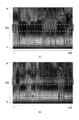
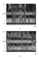
- FIG. 6 and FIG. 7 are diagrams (spectrograms) representing received power (reflection intensity) in each distance FFT bin with the distance from the receiving antenna unit 40 as the vertical axis and the progress of time as the horizontal axis.
- FIG. 6 (A) is a spectrogram in the case of the non-axial deviation state
- FIG. 6 (B) is a spectrogram in the case where the deviation angle ⁇ is ⁇ 1.6 degrees
- FIG. 7A is a spectrogram when the deviation angle ⁇ is ⁇ 2.2 degrees
- FIG. 7B is a spectrogram when the deviation angle ⁇ is ⁇ 3.0 degrees.
- 6 and 7 indicate a specific distance range.
- the low brightness that crosses the range of the specific distance along the distance direction (vertical axis) means that another vehicle or the like has passed.
- the radar apparatus 10 is mounted so that the reference axis BA coincides with the installation reference axis SA.
- the main beam of the radar wave emitted from the radar apparatus 10 attached in this way is usually not reflected on the road surface.
- the received power (reflection intensity) at each distance FFT bin within a specific distance range is small.
- the reference axis BA is inclined downward along the vertical direction with respect to the installation reference axis SA due to vibration or aging due to the traveling of the automobile AM, as shown in FIG.
- the main beam is reflected on the road surface. Radar waves (reflected waves) reflected on the road surface are received by the radar apparatus 10.
- step S280 of the vertical axis deviation determination process if the correlation value is equal to or greater than a predetermined threshold value as a result of collating the road surface reflection intensity with the reference intensity distribution in the non-axis deviation state, the axis deviation is detected. It is assumed that it is in a state.
- the deviation angle ⁇ corresponding to the reference intensity distribution having the maximum correlation value is specified as the inclination angle of the receiving antenna unit 40 with respect to the installation reference axis SA. .
- the radar apparatus 10 can detect an axial deviation state and can specify an inclination angle in the axial deviation state. Further, in the radar apparatus 10, it is not necessary to add a new configuration (structure) to the radar apparatus 10 in order to determine whether or not the axis deviation state is present.
- the radar apparatus 10 it is possible to detect the occurrence of an axis shift while suppressing an increase in the configuration of the radar apparatus 10. Further, the road surface reflection intensity derived by the radar device 10 is obtained by extracting the minimum reception intensity for each distance FFT bin in the transition along the time axis of the reception intensity of the reflected wave from the specific distance range. Has been generated. As a result, the road surface reflection intensity is obtained by passing the transition along the time axis of the reception intensity of the reflected wave from the specific distance range through the minimum value filter.
- the radar apparatus 10 it is possible to remove from the road surface reflection intensity the reflection intensity temporarily increased when the preceding vehicle crosses the front of the host vehicle AM. Thereby, about the road surface reflection intensity, the reflection intensity from the road surface can be expressed more accurately. In other words, according to the radar apparatus 10, it is possible to further improve the detection accuracy as to whether or not the shaft is shifted.
- the radar apparatus 10 that executes vertical axis deviation determination processing is an FMCW radar. For this reason, in the radar apparatus 10, when the host vehicle AM is traveling, the frequency of the beat signal based on the reflected wave from the stationary object is increased by the Doppler shift.
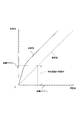
- the frequency that is, the apparent range distance (observed value) Robs shifts in reflection from a stationary object such as a road surface according to the speed Vam of the host vehicle AM.
- the true range distance is Rtru
- the height of the radar from the road surface is H
- the appropriate conversion coefficient is Cr
- This equation (2) is shown in FIG. As shown in FIG. 9, the short range is expanded and observed. Because of the relationship shown in FIG. 9, the resolution of the actually measured value with respect to the ideal value can be reduced at a specific distance (that is, a short distance) where reflection from the road surface is desired to be monitored. For this reason, in the radar apparatus 10, it is possible to further improve the detection accuracy as to whether or not the shaft is shifted.
- step S280 if the result of the collation in step S280 is an axis deviation state, the fact that the axis deviation state is present and the inclination angle of the receiving antenna unit 40 with respect to the installation reference axis SA are reported.
- the in-vehicle system 1 it is possible to make an occupant of the host vehicle AM recognize that the vehicle is in an axial misalignment state. As a result, the installation state of the radar apparatus 10 can be adjusted by a dealer or the like.
- the in-vehicle system of the second embodiment is different from the in-vehicle system 1 of the first embodiment mainly in the vertical axis deviation determination process executed by the signal processing unit 50 of the radar apparatus 10.
- the same configurations and processes as those in the first embodiment are denoted by the same reference numerals, and the description thereof is omitted.
- the vertical axis misalignment determination process different from that in the first embodiment will be mainly described. To do.
- step S410 it is determined whether or not the target detection process has been executed for a predetermined number of measurement cycles. As a result of the determination in step S410, if the target detection process has not been executed the specified number of times (step S410: NO), the vertical axis deviation determination process is terminated, and the process returns to step S160 of the target detection process.
- step S410 determines whether the target detection process has been executed a prescribed number of times.
- step S420 an intensity frequency distribution is derived for each distance FFT bin in the power spectrum obtained in step S140.
- one frequency that is, distance FFT bin
- the power spectrum that is, spectrum distribution
- This intensity frequency distribution represents the correspondence (ie, distribution) between the result of summing up the frequency intensity (hereinafter referred to as frequency intensity frequency) and the frequency intensity in the previously identified distance FFT bin.
- step S440 the intensity frequency distribution in a distance FFT bin (hereinafter referred to as “target FFT bin”) corresponding to a specific distance range from the intensity frequency distribution derived in step S420.
- target FFT bin the intensity frequency distribution in a distance FFT bin corresponding to a specific distance range from the intensity frequency distribution derived in step S420.
- step S430 the intensity frequency distribution in a distance FFT bin
- step S440 the ⁇ (chi) square distribution weighted average m p + 1 is calculated according to the following equation (3) (step S440).
- the sign ⁇ in (3), the probability density of the chi (chi) squared distribution with mean m p, x is a frequency intensity frequency.
- the code p + 1 here is the number of repetitions in one intensity frequency distribution.
- step S440 by substituting the frequency intensity frequency in the intensity frequency distribution derived in step S420 and the average m p into the above equation (3), ⁇ (chi) square distribution weighted average m in the number of iterations p. p is calculated.
- the vertical axis displacement determination processing chi determines that (chi) square distribution with heavy mean m p + 1, chi whether or not the difference between the (chi) square distribution with heavy mean m p satisfies the convergence condition (Step S450).
- the convergence condition in step S450 is, for example, not more than a preset value set in advance as what can be regarded as “0”.
- step S450 if the difference between the ⁇ (chi) square distribution weighted average m p + 1 and the ⁇ (chi) square distribution weighted average m p does not satisfy the convergence condition (step S450). : NO), the repeat count p is incremented by one (step S460). Thereafter, the process returns to step S440, and the ⁇ (chi) square distribution weighted average m p is calculated for the number of repetitions p incremented by one (S440).
- the chi-square distribution weighted average m p-1 for the number of iterations p-1 is set as the center in the chi-square distribution at the number of iterations p, and ⁇ (chi) to calculate the square distribution heavy with average m p.
- step S450 chi (chi) square distribution with heavy with average m p + 1, if they meet the chi (chi) square distribution difference convergence condition with heavy with mean m p (step S450 : YES), the process proceeds to step S470.
- step S470 the frequency intensity frequency corresponding to the ⁇ (chi) square distribution weighted average m p of the number of repetitions p is specified as the road surface reflection intensity for the target FFT bin.
- Step S480 it is determined whether or not Steps S430 to S470 have been executed for all distance FFT bins defined in advance.
- steps S430 to S470 have not been executed for all the predetermined distance FFT bins (step S480: NO)
- the target FFT bin is changed (step S490). )
- the process returns to step S430.
- step S430 the intensity frequency distribution corresponding to the changed target FFT bin is extracted, and then the steps up to step S480 are executed.
- step S480 if step S430 to step S470 are executed for all the predetermined distance FFT bins (step S480: YES), a reflection intensity distribution is generated (step S500). ). This reflection intensity distribution is generated by associating the road surface reflection intensity in each distance FFT bin specified in step S470 with each distance FFT bin.
- an intensity peak FFT bin is specified based on the reflection intensity distribution generated in step S500 (step S510).
- the intensity peak FFT bin is a distance FFT bin in which the road surface reflection intensity is maximum in the reflection intensity distribution.
- step S510 the intensity peak FFT bin specified in step S510 is converted into a distance corresponding to the intensity peak FFT bin (hereinafter referred to as “peak distance”) (step S520). Furthermore, the peak distance is collated with the deviation angle map, and the deviation angle is specified (step S530).
- the deviation angle map here refers to the correspondence between the angle along the vertical direction of the reference axis with respect to the horizontal axis (that is, the deviation angle) and the peak distance, and is obtained in advance by experiments or the like. .
- the peak distance is expressed using a common logarithm, and the downward axis deviation amount increases as the peak distance becomes shorter.
- step S540 various controls based on the deviation angle specified in step S530 are executed (step S540).
- the various controls referred to here may be driving the motor 70 so that the absolute value of the deviation angle of the reference axis with respect to the horizontal axis is less than a prescribed angle defined in advance, or the deviation via the notification device 80. It is also possible to notify the angle.
- the various controls in step S540 may be executed only when the deviation angle is equal to or greater than a specified angle.
- the vertical axis deviation determination process is terminated, and the process returns to step S160 of the target detection process. That is, in the vertical axis deviation determination process of the present embodiment, the frequency intensity (that is, the road surface reflection intensity) that is most likely as the reflection intensity that reflects the radar wave is specified on the road surface in each distance FFT bin. In the vertical axis misalignment determination processing according to the present embodiment, the distance FFT bin having the strongest road surface reflection intensity is identified as the intensity peak FFT bin in the reflection intensity distribution representing the correspondence relationship between the road surface reflection intensity and the distance FFT bin. is doing.
- the deviation angle is identified by comparing the identified intensity peak FFT bin with the deviation angle map, and processing based on the identified deviation angle is executed.
- the intensity peak FFT bin in the reflection intensity distribution is used.
- This intensity peak FFT bin is detected from a plurality of spectrum distributions generated over a predetermined number of measurement cycles, and is most likely as a distance to the road surface where the main beam of the radar wave is reflected.
- the index used to determine whether or not the axis is shifted can be a reflected wave from the road surface, and a reflected wave from a target other than the road surface can be used. Can be excluded.
- the radar device 10 of the present embodiment it is possible to improve the accuracy of determination as to whether or not the shaft is shifted.
- the radar apparatus 10 it is not necessary to add a new configuration (structure) to the radar apparatus 10 in order to determine whether or not the axis is shifted. That is, according to the radar apparatus 10 of the present embodiment, it is possible to detect the occurrence of an axis shift while suppressing an increase in the configuration of the radar apparatus 10.
- the distribution of radar wave reflection intensity from a uniform plane can generally be approximated by a chi-square distribution, and the ideal road surface is a uniform plane.
- the road surface reflection intensity at each distance FFT bin is set to a value at which the weighted average m of the chi-square distribution converges in the intensity frequency distribution.
- the road surface reflection intensity at each distance FFT bin can be specified more accurately, and as a result, a more accurate reflection intensity distribution can be generated. Therefore, according to the radar apparatus 10, it is possible to further improve the determination accuracy as to whether or not the shaft is shifted.
- the deviation peak is identified by collating the intensity peak FFT bin with the deviation angle map, and processing based on the specified deviation angle is executed. For this reason, according to the radar apparatus 10, the misalignment angle can be specified more reliably.
- the mounting angle of the radar apparatus 10 is corrected so that the angle of the reference axis with respect to the horizontal axis is less than the specified angle. Can be maintained.
- step S280 in the vertical axis misalignment determination process in the first embodiment the following two processes (1) and (2) are executed.
- the process executed in step S280 is limited to this. It is not a thing.
- step S280 of the vertical axis misalignment determination process only one of the above (1) and (2) may be executed. Further, in place of the above (1), the radar from the road surface within a specific distance from the receiving antenna unit 40 when the minimum reflection intensity (that is, the minimum reflection intensity) in the road surface reflection intensity is in the non-axial deviation state. As long as it is equal to or higher than the reference reflection intensity, which is the scattering intensity of the main beam of the wave, it may be determined that the axis is in an offset state.
- the frequency modulation period in the radar wave is an up-slope in which the frequency increases linearly (gradual increase) with respect to time, and the frequency is linear.
- the modulation period of the frequency in the radar wave may be a modulation period only in the downlink section in which the frequency decreases linearly (gradual decrease).
- the average mp + 1 with chi (square) square distribution weight is calculated to obtain the road surface reflection intensity, but is used to obtain the road surface reflection intensity.
- the distribution of the reflected wave from the road surface is not limited to the chi-square distribution, but may be approximated by a Gaussian distribution (normal distribution).
- the radar apparatus 10 of the first embodiment is an FMCW radar
- the radar apparatus to which the second invention described in the claims is applied is not limited to the FMCW radar, and is directed in the vertical direction. Any radar device may be used as long as the radar device can identify the reflection intensity for each distance based on a signal received by a receiving antenna having characteristics.
- the radar apparatus 10 of the second embodiment is an FMCW radar.
- the radar apparatus to which the first invention described in the claims is applied is not limited to the FMCW radar and is directed in the vertical direction.
- the oscillator 32, the amplifier 33, the distributor 34, the transmission antenna 36, the antenna 41, the reception switch 42, the mixer 43, the amplifier 44, the filter 45, and the A / D converter. 46 constitutes a transmitting / receiving means.
- the signal processing unit 50 includes target detection means (steps S110 to S140 and steps S150 to S180), deviation determination means (steps S210 to S270: distribution derivation means (step S260), determination means (step S270)), and notification. Means (S280).
- target detection means steps S110 to S140 and steps S150 to S180
- deviation determination means steps S210 to S270: distribution derivation means (step S260), determination means (step S270)
- notification step S280
- the present invention is not limited to this, and any configuration can be applied as long as the function of each unit can be realized.
- the oscillator 32, the amplifier 33, the distributor 34, and the transmission antenna 36 constitute a transmission unit, and an antenna 41, a reception switch 42, a mixer 43, an amplifier 44, and a filter 45.
- the A / D converter 46 constitutes a receiving means.
- the signal processing unit 50 analyzes means (step S140), generating means (steps S410 to S490: frequency deriving means (step S420), specifying means (steps S430 to S460), distribution generating means (step S470)), detecting means.
- Step S510), a deviation determination unit (steps S520 and S530), a correction unit (step S540), and a notification unit (step S540) are configured.
- the present invention is not limited to this, and any configuration can be applied as long as the function of each unit can be realized.
Landscapes
- Engineering & Computer Science (AREA)
- Radar, Positioning & Navigation (AREA)
- Remote Sensing (AREA)
- Physics & Mathematics (AREA)
- Computer Networks & Wireless Communication (AREA)
- General Physics & Mathematics (AREA)
- Electromagnetism (AREA)
- Radar Systems Or Details Thereof (AREA)
Abstract
車両に搭載されるレーダ装置は、連続波からなるレーダ波を送信し、その反射波を、垂直指向性を有した受信アンテナにて受信して送信レーダ波と混合してビート信号を生成し、その周波数解析により、ビート信号に含まれる周波数と各周波数成分の強度とを対応付けたスペクトル分布を生成する。レーダ装置は、予め規定された規定回数分の測定サイクルに渡って、生成された複数のスペクトル分布に基づいて、各周波数と、各周波数における路面からのレーダ波の反射強度を表す路面反射強度とを対応付けた反射強度分布を生成し、その反射強度分布において、路面反射強度が最大となる周波数を表す強度ピークを検出する。レーダ装置は、車両に規定された水平軸に対して、当該レーダ装置の基準軸が車高方向に沿って予め規定された規定角度以上の傾きを有した状態を軸ズレ状態としたときに、検出した強度ピークに基づいて、少なくとも、軸ズレ状態であるか否かを判定する。
Description
本発明は、レーダ波を送受信した結果に基づいて物標を検出するレーダ装置、その軸ズレ検査方法、及びレーダ装置にて実行されるプログラムを記録したコンピュータ読み取り可能な記録媒体に関する。
従来、レーダ波を送信する送信部と、そのレーダ波の反射波を受信アンテナにて受信する受信部と、レーダ波を送受信した結果に基づいて、レーダ波を反射した物体を検出する信号処理部とを備え、車両に搭載されるレーダ装置が知られている(特許文献1参照)。
この種のレーダ装置は、水平面に沿うように車両に規定された設置基準軸に、レーダ装置自身に設定された基準軸が一致するように車両に取り付けられる。このように取り付けられたレーダ装置であっても、自動車が走行することによる振動や経年変化などにより、設置基準軸に対して基準軸が垂直方向(車高方向)に沿って下向き(不一致)となる軸ズレが発生する可能性がある。
下向きの軸ズレが発生すると、レーダ装置では、路面に設置された物体(工事用鉄板など)を、先行車両や道路標識として誤検出してしまう可能性があった。このような誤検出が発生すると、オートクルーズ制御やプリクラッシュセーフティシステムにおいて、検出性能が劣化したり、誤検出が発生したりするなど、レーダ装置としての期待性能が劣化する可能性があった。
このため、下向きの軸ズレが発生した場合には、設置基準軸に基準軸が一致するようにレーダ装置の設置状態を修正する必要があり、下向きの軸ズレが発生したことを検知することが要望されている。
この要望を達成する方法の一つとして、複数の受信アンテナを垂直方向及び水平方向に沿って二次元配置することで受信部を構成し、その受信部にて受信した反射波に基づいて検出した垂直方向の角度に従って下向きの軸ズレが発生したことを検知することが考えられる。また、上記の要望を達成する方法の他の例として、レーダ装置を構成する部材として傾斜角センサを追加し、その傾斜角センサの検出結果に従ってレーダ装置の傾きを検出することが考えられる。
しかしながら、上記の達成方法では、レーダ装置の構成が大型化するという課題が生じる。
つまり、従来の技術では、レーダ装置の構成が大型化することを抑制しつつ、軸ズレの発生を検知することが困難であるという課題があった。
そこで、本発明は、レーダ装置の構成が大型化することを抑制しつつ、軸ズレの発生を検知することを目的とする。
上記目的を達成するためになされた本発明は、車両に搭載されるレーダ装置に関する。
第1発明のレーダ装置は、送信手段、受信手段、解析手段、生成手段、検出手段、及びズレ判定手段を備えている。
このうち、送信手段は、連続波からなるレーダ波を、規定された測定サイクルごとに送信する。受信手段は、送信手段にて送信されたレーダ波の反射波を垂直指向性を有した受信アンテナにて受信し、その受信した反射波に送信手段にて送信するレーダ波を混合して、測定サイクルごとにビート信号を生成する。
そして、解析手段は、受信手段でビート信号を生成するごとに、その生成したビート信号を周波数解析し、ビート信号に含まれる周波数と各周波数成分の強度である周波数強度とを対応付けたスペクトル分布を生成する。生成手段は、予め規定された規定回数分の測定サイクルに渡って解析手段で生成された複数のスペクトル分布に基づいて、各周波数と、各周波数における路面からのレーダ波の反射強度を表す路面反射強度とを対応付けた反射強度分布を生成する。
さらに、検出手段は、生成手段で生成した反射強度分布において、路面反射強度が最大となる周波数を表す強度ピークを検出する。ズレ判定手段は、検出手段で検出した強度ピークに基づいて、少なくとも、軸ズレ状態であるか否かを判定する。ここで言う軸ズレ状態とは、車両に規定された水平軸に対して、当該レーダ装置の基準軸が車高方向に沿って予め規定された規定角度以上の傾きを有した状態である。
すなわち、レーダ装置が搭載された車両が走行する道路上には、通常、先行車両や障害物などが存在する。このため、レーダ装置においては、路面からの反射波だけでなく、先行車両や障害物などからの反射波も受信する。
このように、先行車両や障害物などからの反射波を受信すると、従来のレーダ装置では、軸ズレ状態であるか否かを判定する際に、路面からの反射波、ひいては、路面からの反射強度だけを用いることができず、軸ズレ状態であるか否かの判定精度が悪いという課題があった。つまり、従来の技術においては、軸ズレ状態であるか否かの判定精度をより向上させることが求められている。
これに対し、第1発明のレーダ装置では、軸ズレ状態であるか否かを判定する際に、反射強度分布における強度ピークを用いている。この強度ピークは、規定回数分の測定サイクルに渡って生成された複数のスペクトル分布から検出され、レーダ波の主ビームが反射される路面までの距離として最も可能性が高いものである。
したがって、第1発明のレーダ装置によれば、軸ズレ状態であるか否かの判定に用いる指標を強度ピークとしているため、軸ズレ状態であるか否かを判定する際の指標から、路面以外の物標からの反射波を極力除外できる。この結果、第1発明のレーダ装置によれば、軸ズレ状態であるか否かの判定精度を向上させることができる。
特に、第1発明のレーダ装置においては、軸ズレ状態であるか否かを判定するために、レーダ装置に新たな構成(構造)を付加する必要がない。つまり、第1発明によれば、レーダ装置の構成が大型化することを抑制しつつ、軸ズレの発生を検知することができる。
また、第2発明のレーダ装置は、送受信手段と、物標検出手段と、ズレ判定手段とを備えたものであっても良い。第2発明の送受信手段は、電磁波からなるレーダ波を送信し、その送信されたレーダ波の反射波を、車両の車高方向に沿った垂直指向性を有した受信アンテナで受信する。そして、物標検出手段は、送受信手段にてレーダ波を送受信した結果に基づいて、レーダ波を反射した物標を検出する。
さらに、ズレ判定手段は、送受信手段にてレーダ波を送受信した結果に基づいて、特定距離内における最小の反射強度(以下、「最小反射強度」と称す)が基準反射強度以上であれば、軸ズレ状態であるものと判定する。
通常、第2発明のレーダ装置においては、送受信手段が送信するレーダ波の主ビームが路面で反射されないように車両に取り付けられる。このため、レーダ装置の設置状態が非軸ズレ状態であり、かつ、先行車両などが道路上に存在していなければ、レーダ波は反射されず、最小反射強度は小さな値となる。
そして、水平軸に対して基準軸が車高方向に沿って下向きの傾きを有していても、その傾きの角度が小さい場合には、レーダ波の主ビームが反射される路面の位置は、レーダ装置から離れた位置となる。この場合、レーダ装置の受信アンテナから距離が近い位置に存在する路面には、主ビームは照射されない。このため、最小反射強度は、非軸ズレ状態である場合の最小反射強度に比べたら大きいものの、基準反射強度と比べたら小さいものとなる。
しかしながら、下向きの傾き角度が大きいと、レーダ波の主ビームが反射される路面の位置は、レーダ装置の受信アンテナからの距離が近くなり、その最小反射強度は基準反射強度よりも大きくなる。
つまり、第2発明においては、最小反射強度を基準反射強度と比較することで、軸ズレ状態であるか否かを判定できる。ただし、第2発明における「特定距離」とは、水平軸に対する基準軸の車高方向に沿った下向きの傾きが規定角度以上となった場合に、主ビームが反射される路面までの受信アンテナからの距離の範囲である。また、「基準反射強度」とは、非軸ズレ状態である場合における受信アンテナから特定距離内の路面からのレーダ波の主ビームの散乱強度である。
特に、第2発明のレーダ装置においては、軸ズレ状態であるか否かを判定するために、レーダ装置に新たな構成(構造)を付加する必要がない。つまり、第2発明によれば、レーダ装置の構成が大型化することを抑制しつつ、軸ズレの発生を検知することができる。
ところで、本発明は、レーダ装置が有するコンピュータが実行するプログラムとしてなされていても良い。また、本発明は、当該プログラムが記録された記録媒体、軸ズレ状態の検査方法など、種々の態様で実現できる。
例えば、本発明をプログラムとして構成すれば、DVD-ROM(digital versatile disk read only memory)、CD-ROM(compact disc read only memory)、ハードディスク等のコンピュータ読み取り可能な記録媒体に記録し、必要に応じてコンピュータにロードさせて起動することや、必要に応じて通信回線を介してコンピュータに取得させて起動することにより用いることができる。そして、コンピュータに各手順を実行させることで、そのコンピュータを、レーダ装置が備える上記の手段として機能させることができる。
なお、「請求の範囲」の欄に記載した括弧内の符号は、一つの態様として後述する実施形態に記載の具体的手段との対応関係を示すものであって、本発明の技術的範囲を限定するものではない。
以下に本発明の実施形態を図面と共に説明する。
[第1実施形態]
図1に示す車載システム1は、レーダ装置10と、運転支援ECU(electronic control unit)60と、報知装置80と、モータ70とを備え、アダプティブクルーズコントロール(ACC)や、プリクラッシュセーフティシステム(PCS)などの周知の運転支援制御を実現するシステムである。
図1に示す車載システム1は、レーダ装置10と、運転支援ECU(electronic control unit)60と、報知装置80と、モータ70とを備え、アダプティブクルーズコントロール(ACC)や、プリクラッシュセーフティシステム(PCS)などの周知の運転支援制御を実現するシステムである。
〈レーダ装置〉
レーダ装置10は、自動車AM(図2参照)に搭載されるミリ波レーダである。このレーダ装置10は、ミリ波帯の電磁波からなるレーダ波を送信し、物標が反射したレーダ波(反射波)を受信した結果に基づいて、当該物標を検出する。以下、レーダ装置10が搭載された自動車AMを自車両AMと称す。
レーダ装置10は、自動車AM(図2参照)に搭載されるミリ波レーダである。このレーダ装置10は、ミリ波帯の電磁波からなるレーダ波を送信し、物標が反射したレーダ波(反射波)を受信した結果に基づいて、当該物標を検出する。以下、レーダ装置10が搭載された自動車AMを自車両AMと称す。
そのレーダ装置10は、発振器32と、増幅器33と、分配器34と、送信アンテナ36とを備えている。発振器32は、時間に対して周波数が直線的に増加(漸増)する上り区間、及び周波数が直線的に減少(漸減)する下り区間を一変調周期として有するように変調されたミリ波帯の高周波信号を生成する。増幅器33は、発振器32が生成する高周波信号を増幅する。
分配器34は、増幅器33の出力を送信信号Ssとローカル信号Lsとに電力分配する。送信アンテナ36は、送信信号Ssに応じたレーダ波を放射する。レーダ装置10は、さらに、受信アンテナ部40と、受信スイッチ42と、ミキサ43と、増幅器44と、フィルタ45と、A/D変換器46と、信号処理部50とを備えている。
受信アンテナ部40は、レーダ波を受信するN個(Nは、2以上の自然数)のアンテナ411~41Nを備えている。アンテナ411~41Nは、自車両AMの車高方向に沿った指向性(以下、「垂直指向性」とも称す)を有するように配置されている。なお、アンテナ411~41Nのそれぞれには、チャンネルCH1~CHNが割り当てられている。
また、受信スイッチ42は、アンテナ411~41Nのいずれかを順次選択し、選択されたアンテナ411~41Nからの受信信号Srを後段に供給する。ミキサ43は、増幅器44にて増幅された受信信号Srにローカル信号Lsを混合して、送信信号Ssと受信信号Srとの周波数の差を表すビート信号BTを生成する。増幅器44は、ミキサ43から供給されるビート信号BTを増幅する。フィルタ45は、ミキサ43が生成したビート信号BTから不要な信号成分を除去する。A/D変換器46は、フィルタ45の出力をサンプリングしデジタルデータに変換する。
この信号処理部50は、ROM(read only memory)、RAM(random access memory)、CPU(central processing unit)を少なくとも備えた周知のマイクロコンピュータを中心に構成され、さらに、A/D(analog to digital)変換器46を介して取り込んだデータに対して、高速フーリエ変換(FFT)処理等を実行するための演算処理装置(例えば、DSP(digital signal processor))を備えている。
この信号処理部50は、発振器32の起動、停止や、A/D変換器46を介したビート信号BTのサンプリングを制御する。これと共に、信号処理部50は、サンプリングデータを用いた信号処理や、運転支援ECU60との間で、信号処理に必要な情報(例えば、車速等)、及びその信号処理の結果として得られる物標情報を送受信する情報通信処理を実行する。
さらに、信号処理部50は、ビート信号BTのサンプリングデータを用いて、レーダ波を反射した物標を検出すると共に、その物標についての物標情報を生成する物標検出処理を実行する。
なお、信号処理部50のROMには、物標検出処理を信号処理部50が実行するための処理プログラムが格納されている。
以上説明したように、レーダ装置10は、いわゆるFMCW(frequency modulated continuous wave)レーダとして構成されている。
信号処理部50には、モータ70が接続されている。このモータ70は、車高方向に沿ったレーダ装置10の取り付け角度を変更するものである。
〈レーダ装置の設置態様〉
このようなレーダ装置10は、図2に示すように、レーダ波の主ビームが自車両AMの進行方向に向けて照射されるように、自車両AMの前面(例えば、フロントグリル)に搭載される。そして、レーダ装置10の自動車AMへの取り付けは、レーダ装置10自身に設定された基準軸BAが設置基準軸SAに一致するようになされる。この設置基準軸SAとは、路面に対して平行な軸(即ち、水平軸)であり、かつ、自車両AMの進行方向に向けて自動車AMから延出された軸である。
このようなレーダ装置10は、図2に示すように、レーダ波の主ビームが自車両AMの進行方向に向けて照射されるように、自車両AMの前面(例えば、フロントグリル)に搭載される。そして、レーダ装置10の自動車AMへの取り付けは、レーダ装置10自身に設定された基準軸BAが設置基準軸SAに一致するようになされる。この設置基準軸SAとは、路面に対して平行な軸(即ち、水平軸)であり、かつ、自車両AMの進行方向に向けて自動車AMから延出された軸である。
〈レーダ装置の動作概要〉
レーダ装置10では、信号処理部50からの指令に従って発振器32が振動すると、その発振器32で生成され、増幅器33で増幅した高周波信号を、分配器34が電力分配することにより、送信信号Ss及びローカル信号Lsを生成する。さらに、レーダ装置10では、これらの信号のうちの送信信号Ssを、送信アンテナ36を介してレーダ波として送信する。
レーダ装置10では、信号処理部50からの指令に従って発振器32が振動すると、その発振器32で生成され、増幅器33で増幅した高周波信号を、分配器34が電力分配することにより、送信信号Ss及びローカル信号Lsを生成する。さらに、レーダ装置10では、これらの信号のうちの送信信号Ssを、送信アンテナ36を介してレーダ波として送信する。
そして、送信アンテナ36から送出されて物標に反射されたレーダ波(即ち、反射波)は、受信アンテナ部40を構成する全てのアンテナ411~41Nにて受信され、受信スイッチ42によって選択されている受信チャンネルCHi(i=1~N)の受信信号Srのみが増幅器33で増幅された後、ミキサ43に供給される。ミキサ43では、この受信信号Srに分配器34からのローカル信号Lsを混合することによりビート信号BTを生成する。そして、このビート信号BTは、フィルタ45にて不要な信号成分が除去された後、A/D変換器46にてサンプリングされ、信号処理部50に取り込まれる。
なお、受信スイッチ42は、レーダ波の一変調周期の間に、全てのチャンネルCH1からCHNが所定回(例えば、512回)ずつ選択されるよう切り替えられる。また、A/D変換器46は、この切り替えタイミングに同期してサンプリングを実行する。つまり、レーダ波の一変調周期の間に、チャンネルCH1~CHN毎かつレーダ波の上り、及び下り区間毎にサンプリングデータが蓄積されることになる。 そして、信号処理部50は、ビート信号BTのサンプリング値に基づいて、レーダ波を反射した物標を検出すると共に、各物標までの距離、物標との間の相対速度、及び物標が存在する方位(以下、「到来方位」と称す)を導出する。そして、各物標についてのそれらの情報(距離、相対速度、及び到来方位)を含む情報を物標情報として、運転支援ECU60に出力する。
なお、図1に示す運転支援ECU60は、他の車載制御装置や他の車載機器を制御し、運転支援制御を実現する。運転支援制御の一つであるACCは、先行車両と自車両との車間距離を適切な間隔に維持する。運転支援制御の一つであるPCSは、自車両の進行路上に存在する障害物との衝突が回避不可能である場合に、自車両の制動力やシートベルトの拘束力を強化する。
また、報知装置80は、制御信号に従って情報を報知する周知の装置である。この報知装置80には、例えば、情報を表示する表示装置、及び情報を音声にて出力する音声出力装置のうち、少なくとも一つを含む。本実施形態における表示装置には、例えば、ディスプレイと、表示灯(警告灯)とを含む。
〈物標検出処理〉
物標検出処理は、予め規定された周期(即ち、測定サイクル)で起動されるものである。
物標検出処理は、予め規定された周期(即ち、測定サイクル)で起動されるものである。
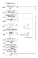
この物標検出処理は、起動されると、図3に示すように、まず、発振器32を起動してレーダ波の送信を開始する(ステップS110)。続いて、A/D変換器46を介してビート信号BTのサンプリング値を取得し(ステップS120)、必要なだけサンプリング値を取得すると、発振器32を停止することにより、レーダ波の送信を停止する(ステップS130)。
次に、ステップS130にて取得したビート信号BTのサンプリング値について周波数解析(本実施形態では、FFT処理)を実行し、受信チャンネルCH1~CHN毎かつ上り/下り区間毎にビート信号BTのパワースペクトルを求める(ステップS140)。このパワースペクトルは、ビート信号BTに含まれる周波数と、各周波数の強度とを表したものである。
さらに、ステップS140では、上り区間について、パワースペクトル上に存在する各周波数ピークfbu1~mを検出すると共に、下り区間について、パワースペクトル上に存在する各周波数ピークfbd1~mを検出する。なお、検出された周波数ピークfbu、fbdの各々は、反射波の発生源となった物標の候補(以下、物標候補と称す)が存在する可能性があることを意味する。
物標検出処理では、続いて、設置基準軸SAに対して基準軸BAが垂直方向(車高方向)に沿って規定角度以上の傾きを有した軸ズレ状態であるか否かを判定する垂直軸ズレ判定処理を実行する(ステップS150)。なお、この垂直軸ズレ判定処理の実施理由は、設置基準軸SAに基準軸BAが一致するように取り付けられたレーダ装置10であっても、自動車AMが走行することによる振動や経年変化などにより、軸ズレ状態となる可能性があるためである。この垂直軸ズレ判定処理の詳細については、後述する。
物標検出処理では、続いて、周波数ピークfbu、fbdの各々について、当該周波数ピークfbu、fbdに対応する物標候補の到来方位、及び当該物標候補からの反射波を受信した受信電力を表す到来電力を推定する方位検出処理を実行する(ステップS160)。この方位検出処理としては、例えば、周知のMUSIC(multiple signal classification)や、デジタルビームフォーミングなどの手法を用いれば良い。なお、本実施形態における到来方位とは、レーダ装置10に設定された基準軸BAに対して、物標が存在する方位(角度)である。
そのステップS160にて推定した到来方位及び到来電力に基づいて、上り区間のビート信号BTから求められた周波数ピークfbu1~mと、下り区間のビート信号BTから求められた周波数ピークfbd1~mとを、同一物標にてレーダ波を反射したとみなせるもの同士でマッチングして登録するペアマッチングを実行する(ステップS170)。以下、マッチングして登録された周波数ピークfbu、fbdの組を、周波数ペアと称す。
具体的に本実施形態のステップS170では、上り区間の周波数ピークfbuと下り区間の周波数ピークfbdとの全ての組合せについて、到来電力の差、及び到来方位の角度差が予め規定された許容範囲内であるか否かを判定する。その判定の結果、到来電力の差及び到来方位の角度差が共に、許容範囲内であれば、対応する周波数ピークの組を周波数ペアとする。
さらに、ステップS170では、登録された周波数ペアに対して、FMCW方式のレーダ装置に周知の手法により、レーダ装置10から物標候補までの距離、物標候補と自車両との相対速度を導出する。本実施形態のステップS170では、物標候補と自車両との相対速度、及び自車両の車速に基づいて、各物標候補の速度を導出すると共に、その物標候補が、停止物体であるか移動物体であるかを判定する。それらの導出した距離及び相対速度(速度)に物標候補が存在する方位を加えた情報を、各周波数ペアと対応付けた上で、物標候補として登録する。
さらに、今回の送受信サイクルのステップS170で登録された周波数ペア(以下、今サイクルペアと称す)の情報(即ち、距離、速度、方位など)と、前回の送受信サイクルで登録された周波数ペア(以下、前サイクルペアと称す)の情報とに基づき、同一物標に対応する周波数ペアを検出する履歴接続処理を実行する(ステップS180)。
具体的に本実施形態の履歴接続処理(ステップS180)では、前サイクルペアと今サイクルペアとの全ての組み合わせ(以下、組合せペアと称す)を設定し、その組合せペアの中からいずれか1つを取り出す。そして、取り出した組合せペアにおける前サイクルペアの情報に基づいて予測され、その前サイクルペアに対応する今サイクルペアが存在する位置(以下、予測位置とする)、及び今サイクルペアの速度(以下、予測速度とする)を導出する。この予測位置及び予測速度の導出は、周知の処理であるため、ここでの詳しい説明は省略するが、例えば、カルマンフィルタなどを用いて、時系列に沿った周波数ペア(即ち、物標候補)の挙動を予測し、その予測した結果を、予測位置及び予測速度とすることが考えられる。
そして、履歴接続処理では、導出した予測位置及び予測速度と、今サイクルペアから導出された位置及び速度とに基づいて、両者の位置差分、及び速度差分を導出する。すなわち、位置差分とは、今サイクルペアから導出された位置(即ち、今サイクルペアに対応する物標候補の位置)と予測位置との差分であり、速度差分とは、今サイクルペアから導出された速度(即ち、今サイクルペアに対応する物標候補の速度)と予測速度との差分である。
さらに、位置差分が予め規定された基準距離より小さく、かつ速度差分が予め規定された上限速度差よりも小さい場合にのみ、当該組合せペアを構成する周波数ペアは同一物標に対応するもの(即ち、履歴接続があるもの)として、今サイクルペアの接続カウンタのカウント値を、前サイクルペアの接続カウンタのカウント値に1を加算した値へと更新する。
つまり、本実施形態の履歴接続処理では、前サイクルペアとの履歴接続がある今サイクルペアは、対応する前サイクルペアの情報(接続カウンタのカウント値)が引き継がれ、前サイクルペアとの履歴接続が無い今サイクルペアについては、接続カウンタのカウント値が0に維持される。
物標検出処理では、さらに、予め規定された認識閾値以上の履歴接続が確認された周波数ペアを物体として認識して登録し、その登録された物標についての物標情報を運転支援ECU60に出力する(ステップS190)。具体的に本実施形態のステップS190では、接続カウンタのカウント値が認識閾値以上である場合に、認識閾値以上の履歴接続が確認されたものとする。
その後、今サイクルの物標検出処理を終了し、次の起動タイミングまで待機する。
〈垂直軸ズレ判定処理〉
次に、物標検出処理のステップS150にて起動される垂直軸ズレ判定処理について説明する。
次に、物標検出処理のステップS150にて起動される垂直軸ズレ判定処理について説明する。
この垂直軸ズレ判定処理は、図4に示すように、先の物標検出処理のS140にて求められた下り区間のパワースペクトルから、予め規定された特定距離の範囲内に含まれる一つの距離FFTビンに対応する路面からの反射強度(受信電力)を抽出する(ステップS210)。
なお、本実施形態における特定距離とは、水平軸(設置基準軸SA)に対する基準軸BAの車高方向に沿った下向きの傾きが規定角度以上となった場合に、レーダ波の主ビームが反射される路面までの受信アンテナ部40からの距離の範囲である。また、反射強度を抽出する対象としてのパワースペクトルは、レーダ装置10からの距離と各距離における反射強度(受信強度)とを、予め規定された距離FFTビンごとに示したものへと変換されている。
そして、路面からの反射強度Prは、下記(1)式によって求めることができる。ただし、(1)式における符号Gtrは、指向性を含む送受信合成利得である。さらに、(1)式において、符号Hは、路面からレーダ装置10までの高さ[m]であり、符号Lは、自車両AMから当該距離FFTビンに対応する路面までの水平方向に沿った距離[m]である(図8(A)参照)。また、(1)式における符号C2は、予め規定された定数である。

そのS210にて抽出した一つの距離FFTビンにおける受信電力(以下、「現反射強度」と称す)を、信号処理部50のRAMに記憶されている当該距離FFTビンにおける受信電力の最小値(以下、「強度最小値」と称す)と比較する(ステップS220)。そのステップS220での比較の結果、現反射強度が強度最小値よりも小さければ(ステップS230:YES)、ステップS210にて抽出した現反射強度を強度最小値として、信号処理部50のRAMに記憶する(ステップS240)。すなわち、ステップS240では、強度最小値を更新する。
その後、ステップS250へと移行する。一方、ステップS220での比較の結果、現反射強度が強度最小値以上であれば(ステップS230:NO)、ステップS240を実行することなく、ステップS250へと進む。
そのステップS250では、特定距離の範囲内に含まれる全ての距離FFTビンの受信電力(反射強度)について、ステップ210からステップS240を実行したか否かを判定する。その判定の結果、全ての距離FFTビンの受信電力(反射強度)について、ステップS210からステップS240を実行していなければ(ステップS250:NO)、ステップS210へと戻る。ステップS250を経て移行したステップS210では、ステップS210からステップS250を未実行である一つの距離FFTビンの受信電力(反射強度)を抽出して、ステップS220へと移行する。
一方、ステップS250での判定の結果、全ての距離FFTビンの受信電力(反射強度)について、ステップS210からステップS240を実行していれば(ステップS250:YES)、ステップS260へと移行する。
そのステップS260では、予め規定された周期の回数(以下、「規定回数」と称す)分、物標検出処理が終了したか否かを判定する。ここで言う規定回数とは、レーダ装置10が起動されてから、所定の時間(例えば、30分)に実行可能な変調周期の回数として規定されたものである。
そして、ステップS260での判定の結果、物標検出処理を規定回数終了していなければ(ステップS260:NO)、本垂直軸ズレ判定処理を終了し、物標検出処理へと戻る。一方、ステップS260での判定の結果、物標検出処理を規定回数終了していれば(ステップS260:YES)、信号処理部50のRAMから路面反射強度を抽出する(ステップS270)。
このステップS270にて抽出される路面反射強度とは、信号処理部50のRAMに記憶されている強度最小値を、各距離FFTビンについて受信アンテナ部40からの距離に沿って配置した反射強度の分布である。この路面反射強度は、特許請求の範囲に記載された「最小反射強度」に相当する。
続いて、ステップS270にて抽出した路面反射強度を、予め用意された基準強度分布それぞれに照合する(ステップS280)。本実施形態における基準強度分布は、図5に示すように、路面からのレーダ波の主ビームの散乱強度を受信アンテナ部40からの距離に沿って表したものである。この基準強度分布には、受信アンテナ部40から特定距離内の路面からのレーダ波の主ビームの反射強度、即ち、特定距離に位置する路面からの反射波の受信強度(以下、「特定反射強度」と称す)が含まれる。
この特定反射強度は、設置基準軸SAに対する基準軸BAのなす角度として規定されたズレ角度(即ち、傾斜角度)θ(図8参照)ごとに、予め実験などで求められたものである。そして、基準反射強度それぞれは、ズレ角度θごとに予め用意されている。特定反射強度が求められるズレ角度θには、0度、即ち、非軸ズレ状態である場合を含む。この非軸ズレ状態である場合に求められた特定反射強度が、特許請求の範囲に記載された基準反射強度に相当する。
さらに、特定反射強度が求められるズレ角度θには、設置基準軸SAに対して基準軸BAが垂直方向に沿った下向きの複数の角度(例えば、-1.6度や、-3.0度)を含む。
なお、本実施形態のステップS280では、非軸ズレ状態である場合の基準強度分布に路面反射強度を照合した結果、相関値が、予め規定された規定閾値以上であれば、軸ズレ状態であるものとする。そして、基準強度分布それぞれに路面反射強度を照合した結果、相関値が最大となる基準強度分布に対応するズレ角度θを、設置基準軸SAに対する受信アンテナ部40の傾き角として特定する。
ステップS280での照合結果を報知装置80から報知する(ステップS290)。すなわち、ステップS290では、軸ズレ状態であれば、軸ズレ状態である旨、及び設置基準軸SAに対する受信アンテナ部40の傾き角が報知される。
その後、本垂直軸ズレ判定処理を終了し、物標検出処理のステップS160へと戻る。
ここで、図6、図7は、受信アンテナ部40からの距離を縦軸とし、時間の進行を横軸として、各距離FFTビンにおける受信電力(反射強度)を表した図(スペクトログラム)である。このうち、図6(A)は、非軸ズレ状態である場合のスペクトログラムであり、図6(B)は、ズレ角度θが-1.6度である場合のスペクトログラムである。また、図7(A)は、ズレ角度θが-2.2度である場合のスペクトログラムであり、図7(B)は、ズレ角度θが-3.0度である場合のスペクトログラムである。
なお、図6、図7における破線で囲った枠は、特定距離の範囲を表し、この特定距離の範囲においては、明度が低いほど受信電力(反射強度)が小さく、かつ、明度が高いほど受信電力(反射強度)が大きいことを表す。ただし、特定距離の範囲を距離方向(縦軸)に沿って横切る低い明度は、他の車両などが通過したことを意味している。
通常、レーダ装置10は、設置基準軸SAに基準軸BAが一致するように取り付けられる。このように取り付けられたレーダ装置10から出射されたレーダ波の主ビームは、通常、路面では反射されない。
したがって、図6(A)に示すように、特定距離の範囲内における各距離FFTビンでの受信電力(反射強度)は小さなものとなる。しかしながら、自動車AMが走行することによる振動や経年変化などにより、設置基準軸SAに対して垂直方向に沿った下向きに基準軸BAが傾くと、図8(A)に示すように、レーダ波の主ビームが路面にて反射される。この路面にて反射されたレーダ波(反射波)は、レーダ装置10にて受信される。
そして、図8(B)に示すように、設置基準軸SAに対する垂直方向に沿った基準軸BAの下向きの角度が大きくなると、レーダ波の主ビームを反射する路面の位置がレーダ装置に近くなる。この場合、レーダ装置10にて受信される路面からのレーダ波の反射強度は大きくなる。しかも、図6(B)、図7(A)、図7(B)に示すように、ズレ角度θが大きくなるほど、受信電力(反射強度)は大きくなる。
[第1実施形態の効果]
以上説明したように、レーダ装置10によれば、基準強度分布それぞれに路面反射強度を照合することで、軸ズレ状態であるか否かを判定できる。
以上説明したように、レーダ装置10によれば、基準強度分布それぞれに路面反射強度を照合することで、軸ズレ状態であるか否かを判定できる。
特に、垂直軸ズレ判定処理のステップS280においては、非軸ズレ状態である場合の基準強度分布に路面反射強度を照合した結果、相関値が、予め規定された規定閾値以上であれば、軸ズレ状態であるものとする。これと共に、基準強度分布それぞれに路面反射強度を照合した結果、相関値が最大となる基準強度分布に対応するズレ角度θを、設置基準軸SAに対する受信アンテナ部40の傾き角として特定している。
このため、レーダ装置10においては、軸ズレ状態であることを検知できると共に、その軸ズレ状態である場合の傾き角を特定できる。また、レーダ装置10においては、軸ズレ状態であるか否かを判定するために、レーダ装置10に新たな構成(構造)を付加する必要がない。
したがって、レーダ装置10によれば、レーダ装置10の構成が大型化することを抑制しつつ、軸ズレの発生を検知することができる。また、レーダ装置10にて導出される路面反射強度は、特定距離範囲からの反射波の受信強度の時間軸に沿った推移の中で、各距離FFTビンについて最小の受信強度を抽出することで生成されている。この結果、路面反射強度は、特定距離範囲からの反射波の受信強度の時間軸に沿った推移を最小値フィルタに通したものである。
つまり、レーダ装置10によれば、先行車両が自車両AMの前方を横切った場合などに一時的に強くなった反射強度を路面反射強度から除去することができる。これにより、路面反射強度について、路面からの反射強度をより正確に表したものとすることができる。換言すれば、レーダ装置10によれば、軸ズレ状態であるか否かの検知精度をより向上させることができる。
さらに、垂直軸ズレ判定処理を実行するレーダ装置10は、FMCWレーダである。このため、レーダ装置10では、自車両AMが走行中である場合には、ドップラーシフトによって、静止物からの反射波に基づくビート信号の周波数は高くなる。
このようなレーダ装置10によれば、路面のような静止物からの反射は自車両AMの速度Vamに応じて周波数すなわち見かけのレンジ距離(観測値)Robsが偏移する。真のレンジ距離(理想値)をRtruとし、路面からのレーダの高さをH、適切な変換係数をCrとすれば、下記(2)式の関係がある。

ところで、垂直軸ズレ判定処理では、ステップS280での照合の結果、軸ズレ状態であれば、軸ズレ状態である旨、及び設置基準軸SAに対する受信アンテナ部40の傾き角を報知している。
このため、車載システム1によれば、自車両AMの乗員に軸ズレ状態であることを認識させることができる。この結果、レーダ装置10の設置状態をディーラなどにて調整させることができる。
[第2実施形態]
第2実施形態の車載システムは、第1実施形態の車載システム1とは、主として、レーダ装置10の信号処理部50が実行する垂直軸ズレ判定処理が異なる。このため、本実施形態においては、第1実施形態と同様の構成及び処理には、同一の符号を付して説明を省略し、第1実施形態とは異なる垂直軸ズレ判定処理を中心に説明する。
第2実施形態の車載システムは、第1実施形態の車載システム1とは、主として、レーダ装置10の信号処理部50が実行する垂直軸ズレ判定処理が異なる。このため、本実施形態においては、第1実施形態と同様の構成及び処理には、同一の符号を付して説明を省略し、第1実施形態とは異なる垂直軸ズレ判定処理を中心に説明する。
<垂直軸ズレ判定処理>
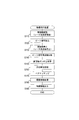
本実施形態における垂直軸ズレ判定処理は、図10に示すように、まず、予め規定された規定回数の測定サイクル分、物標検出処理を実行したか否かを判定する(ステップS410)。このステップS410での判定の結果、物標検出処理を規定回数実行していなければ(ステップS410:NO)、本垂直軸ズレ判定処理を終了して、物標検出処理のステップS160へと戻る。
本実施形態における垂直軸ズレ判定処理は、図10に示すように、まず、予め規定された規定回数の測定サイクル分、物標検出処理を実行したか否かを判定する(ステップS410)。このステップS410での判定の結果、物標検出処理を規定回数実行していなければ(ステップS410:NO)、本垂直軸ズレ判定処理を終了して、物標検出処理のステップS160へと戻る。
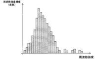
一方、ステップS410での判定の結果、物標検出処理を規定回数実行していれば(ステップS410:YES)、ステップS140にて求めたパワースペクトルにおける距離FFTビンそれぞれについて、強度度数分布を導出する(ステップS420)。具体的に、ステップS410では、先のステップS140にて求めたパワースペクトル(即ち、スペクトル分布)における1つの周波数(即ち、距離FFTビン)を特定する。その特定した距離FFTビンについて、規定回数分の測定サイクルに渡る周波数強度を集計する。そして、図11に示すような強度度数分布を導出する。
この強度度数分布は、周波数強度を集計した結果(以下、周波数強度頻度と称す)と、先に特定した距離FFTビンにおける周波数強度との対応関係(即ち、分布)表すものである。
この一連の処理を、パワースペクトルにおける全ての距離FFTビンについて実行する。続いて、垂直軸ズレ判定処理では、ステップS420で導出した強度度数分布の中から、特定の距離の範囲内に対応する距離FFTビン(以下、「対象FFTビン」と称す)での強度度数分布を抽出する(ステップS430)。さらに、ステップS430で抽出した強度度数分布に基づいて、下記(3)式に従って、χ(カイ)二乗分布重付き平均mp+1を算出する(ステップS440)。

すなわち、ステップS440では、ステップS420で導出した強度度数分布における周波数強度頻度、及び平均mpを、上記(3)式に代入することで、繰り返し回数pにおけるχ(カイ)二乗分布重付き平均mpを算出する。
さらに、垂直軸ズレ判定処理では、χ(カイ)二乗分布重付き平均mp+1と、χ(カイ)二乗分布重付き平均mpとの差分が収束条件を満たしているか否かを判定する(ステップS450)。このステップS450における収束条件は、例えば、「0」とみなせるものとして予め設定された設定値以下であることである。
そして、ステップS450での判定の結果、χ(カイ)二乗分布重付き平均mp+1と、χ(カイ)二乗分布重付き平均mpとの差分が収束条件を満たしていなければ(ステップS450:NO)、繰り返し回数pを1つインクリメントする(ステップS460)。その後、ステップS440へと戻り、その1つインクリメントした繰り返し回数pについてのχ(カイ)二乗分布重付き平均mpを算出する(S440)。具体的に、S440では、繰り返し回数p-1についてのχ(カイ)二乗分布重付き平均mp-1を、繰り返し回数pでのχ(カイ)二乗分布における中心として設定し、χ(カイ)二乗分布重付き平均mpを算出する。
一方、ステップS450での判定の結果、χ(カイ)二乗分布重付き平均mp+1と、χ(カイ)二乗分布重付き平均mpとの差分が収束条件を満たしていれば(ステップS450:YES)、ステップS470へと移行する。そのステップS470では、繰り返し回数pのχ(カイ)二乗分布重付き平均mpに対応する周波数強度頻度を、対象FFTビンに対する路面反射強度として特定する。
続いて、予め規定された全ての距離FFTビンに対して、ステップS430からステップS470を実行したか否かを判定する(ステップS480)。このステップS480での判定の結果、予め規定された全ての距離FFTビンに対して、ステップS430からステップS470を実行していなければ(ステップS480:NO)、対象FFTビンを変更して(ステップS490)、ステップS430へと戻る。そのステップS430では、変更された対象FFTビンに対応する強度度数分布を抽出し、その後、ステップS480までのステップを実行する。
一方、ステップS480での判定の結果、予め規定された全ての距離FFTビンに対して、ステップS430からステップS470を実行していれば(ステップS480:YES)、反射強度分布を生成する(ステップS500)。この反射強度分布は、ステップS470にて特定した各距離FFTビンにおける路面反射強度と、各距離FFTビンのそれぞれとを対応付けることで生成される。
続いて、ステップS500で生成された反射強度分布に基づいて、強度ピークFFTビンを特定する(ステップS510)。強度ピークFFTビンとは、反射強度分布において、路面反射強度が最大となる距離FFTビンである。
そして、ステップS510にて特定した強度ピークFFTビンを、その強度ピークFFTビンに対応する距離(以下、「ピーク距離」と称す)へと変換する(ステップS520)。さらに、そのピーク距離をズレ角度マップに照合し、ズレ角度を特定する(ステップS530)。
ここで言うズレ角度マップとは、水平軸に対する基準軸の垂直方向に沿った角度(即ち、ズレ角度)とピーク距離との対応関係を表すものであり、実験などにより予め求められたものである。ただし、本実施形態におけるズレ角度マップは、図12に示すように、ピーク距離は、常用対数を用いて表され、ピーク距離が近距離になるほど下向きの軸ズレ量が大きくなっている。
さらに、垂直軸ズレ判定処理では、ステップS530で特定したズレ角度に基づく各種制御を実行する(ステップS540)。ここで言う各種制御とは、水平軸に対する基準軸のズレ角度の絶対値が、予め規定された規定角度未満となるように、モータ70を駆動することでも良いし、報知装置80を介してズレ角度を報知することでも良い。特に、ステップS540における各種制御は、ズレ角度が規定角度以上となった場合にだけ実行しても良い。
その後、本垂直軸ズレ判定処理を終了して、物標検出処理のステップS160へと戻る。つまり、本実施形態の垂直軸ズレ判定処理では、各距離FFTビンにおける路面にて、レーダ波を反射した反射強度として最も可能性が高い周波数強度(即ち、路面反射強度)を特定する。そして、本実施形態の垂直軸ズレ判定処理では、その路面反射強度と、距離FFTビンとの対応関係を表す反射強度分布において、路面反射強度が最も強い距離FFTビンを、強度ピークFFTビンとして特定している。
さらに、本実施形態の垂直軸ズレ判定処理では、その特定した強度ピークFFTビンをズレ角度マップに照合することで、ズレ角度を特定し、その特定したズレ角度に基づく処理を実行している。
[第2実施形態の効果]
すなわち、レーダ装置10が搭載された自動車AMが走行する道路上には、通常、先行車両や障害物などが存在する。このため、レーダ装置10においては、路面からの反射波だけでなく、先行車両や障害物などからの反射波も受信する。
すなわち、レーダ装置10が搭載された自動車AMが走行する道路上には、通常、先行車両や障害物などが存在する。このため、レーダ装置10においては、路面からの反射波だけでなく、先行車両や障害物などからの反射波も受信する。
このように、先行車両や障害物などからの反射波を受信すると、従来のレーダ装置では、軸ズレ状態であるか否かを判定する際に、路面からの反射波、ひいては、路面からの反射強度だけを用いることができず、軸ズレ状態であるか否かの判定精度が悪いという課題があった。つまり、従来の技術においては、軸ズレ状態であるか否かの判定精度をより向上させることが求められている。
これに対し、本実施形態のレーダ装置10では、軸ズレ状態であるか否かを判定する際に、反射強度分布における強度ピークFFTビンを用いている。この強度ピークFFTビンは、規定回数分の測定サイクルに渡って生成された複数のスペクトル分布から検出され、レーダ波の主ビームが反射される路面までの距離として最も可能性が高いものである。
したがって、本実施形態のレーダ装置10によれば、軸ズレ状態であるか否かを判定する際の指標を、路面からの反射波とすることができ、路面以外の物標からの反射波を除外できる。この結果、本実施形態のレーダ装置10によれば、軸ズレ状態であるか否かの判定精度を向上させることができる。
特に、本実施形態のレーダ装置10においては、軸ズレ状態であるか否かを判定するために、レーダ装置10に新たな構成(構造)を付加する必要がない。つまり、本実施形態のレーダ装置10によれば、レーダ装置10の構成が大型化することを抑制しつつ、軸ズレの発生を検知することができる。
ところで、一様な平面からのレーダ波の反射強度の分布(即ち、路面強度分布)は、一般的に、カイ二乗分布にて近似でき、理想的な路面は、一様な平面である。そして、本実施形態のレーダ装置10では、各距離FFTビンでの路面反射強度を、強度度数分布において、カイ二乗分布の重み付き平均mが収束する値としている。
このため、本実施形態のレーダ装置10によれば、各距離FFTビンでの路面反射強度をより正確に特定することができ、ひいては、より高精度な反射強度分布を生成できる。したがって、レーダ装置10によれば、軸ズレ状態であるか否かの判定精度をより向上させることができる。
また、本実施形態のレーダ装置10では、強度ピークFFTビンをズレ角度マップに照合することで、ズレ角度を特定し、その特定したズレ角度に基づく処理を実行している。このため、レーダ装置10によれば、ズレ角度をより確実に特定できる。
しかも、レーダ装置10によれば、水平軸に対する基準軸の角度が規定角度未満となるように、レーダ装置10の取り付け角度を修正しているため、レーダ装置10における物標の存在位置の検出精度を維持できる。
[その他の実施形態]
以上、本発明の実施形態について説明したが、本発明は上記実施形態に限定されるものではなく、本発明の要旨を逸脱しない範囲において、様々な態様にて実施することが可能である。
以上、本発明の実施形態について説明したが、本発明は上記実施形態に限定されるものではなく、本発明の要旨を逸脱しない範囲において、様々な態様にて実施することが可能である。
例えば、上記第1実施形態における垂直軸ズレ判定処理におけるステップS280では、以下の(1)、(2)の2つの処理を実行していたが、ステップS280にて実行する処理は、これに限るものではない。
(1) 非軸ズレ状態である場合の基準強度分布に路面反射強度を照合した結果、相関値が、予め規定された規定閾値以上であれば、軸ズレ状態であるものとする処理。
(2) 基準強度分布それぞれに路面反射強度を照合した結果、相関値が最大となる基準強度分布に対応するズレ角度θを、設置基準軸SAに対する受信アンテナ部40の傾き角として特定する処理。
すなわち、垂直軸ズレ判定処理のステップS280では、上記(1)、(2)のいずれか一方のみを実行しても良い。さらに、上記(1)に換えて、路面反射強度の中で最小の反射強度(即ち、最小反射強度)が、非軸ズレ状態である場合における受信アンテナ部40から特定距離内の路面からのレーダ波の主ビームの散乱強度である基準反射強度以上であれば、軸ズレ状態であるものと判定しても良い。
また、上記第1実施形態、及び第2実施形態におけるレーダ装置10では、レーダ波における周波数の変調周期を、時間に対して周波数が直線的に増加(漸増)する上り区間、及び周波数が直線的に減少(漸減)する下り区間を一変調周期として有するものとしていたが、レーダ波における周波数の変調周期は、周波数が直線的に減少(漸減)する下り区間のみを一変調周期としていても良い。
ところで、第2実施形態における垂直軸ズレ判定処理では、χ(カイ)二乗分布重付き平均mp+1を算出して、路面反射強度を求めていたが、路面反射強度を求めるために用いる、路面からの反射波の分布は、カイ二乗分布に限るものではなく、ガウス分布(正規分布)で近似してもよい。
さらに、上記第1実施形態のレーダ装置10は、FMCWレーダであったが、特許請求の範囲の記載における第2発明が適用されるレーダ装置は、FMCWレーダに限るものではなく、垂直方向に指向性を有した受信アンテナにて受信した信号に基づいて、距離ごとの反射強度を特定可能なレーダ装置であれば、どのようなレーダ装置であっても良い。
また、上記第2実施形態のレーダ装置10は、FMCWレーダであったが、特許請求の範囲の記載における第1発明が適用されるレーダ装置は、FMCWレーダに限るものではなく、垂直方向に指向性を有した受信アンテナにて受信した信号に基づいて、距離ごとの反射強度を特定可能なレーダ装置、例えば、CW(continuous wave)レーダであっても良いし、2周波CWレーダであっても良い。
なお、上記実施形態の構成の一部を、課題を解決できる限りにおいて省略した態様も本発明の実施形態である。また、上記実施形態と変形例とを適宜組み合わせて構成される態様も本発明の実施形態である。また、特許請求の範囲に記載した文言によって特定される発明の本質を逸脱しない限度において考え得るあらゆる態様も本発明の実施形態である。
例えば、第1実施形態に係るレーダ装置10の内、発振器32、増幅器33、分配器34、送信アンテナ36、アンテナ41、受信スイッチ42、ミキサ43、増幅器44、フィルタ45、及びA/D変換器46が送受信手段を構成している。また、信号処理部50が物標検出手段(ステップS110~S140及びステップS150~S180)、ズレ判定手段(ステップS210~S270:分布導出手段(ステップS260)、判定手段(ステップS270))、及び報知手段(S280)を構成している。しかし、本発明はこれに限定されず、各手段の機能を実現可能な構成であれば、いずれの構成でも適用可能である。
また、第2実施形態に係るレーダ装置10の内、発振器32、増幅器33、分配器34、及び送信アンテナ36が送信手段を構成し、アンテナ41、受信スイッチ42、ミキサ43、増幅器44、フィルタ45、A/D変換器46が受信手段を構成している。また、信号処理部50が解析手段(ステップS140)、生成手段(ステップS410~S490:度数導出手段(ステップS420)、特定手段(ステップS430~S460)、分布生成手段(ステップS470))、検出手段(ステップS510)、ズレ判定手段(ステップS520、S530)、補正手段(ステップS540)、報知手段(ステップS540)を構成している。しかし、本発明はこれに限定されず、各手段の機能を実現可能な構成であれば、いずれの構成でも適用可能である。
1…車載システム 10…レーダ装置 32…発振器 33…増幅器 34…分配器 36…送信アンテナ 40…受信アンテナ部 41…アンテナ 42…受信スイッチ 43…ミキサ 44…増幅器 45…フィルタ 46…A/D変換器 50…信号処理部 60…運転支援ECU 80…報知装置
Claims (15)
- 車両に搭載されるレーダ装置(10)であって、
連続波からなるレーダ波を、規定された測定サイクルごとに送信する送信手段(32~36)と、
前記送信手段にて送信されたレーダ波の反射波を垂直指向性を有した受信アンテナにて受信し、その受信した反射波に前記送信手段にて送信するレーダ波を混合して、前記測定サイクルごとにビート信号を生成する受信手段(41~46)と、
前記受信手段でビート信号を生成するごとに、該ビート信号を周波数解析し、前記ビート信号に含まれる周波数と各周波数成分の強度である周波数強度とを対応付けたスペクトル分布を生成する解析手段(50、S140)と、
予め規定された規定回数分の測定サイクルに渡って前記解析手段で生成された複数のスペクトル分布に基づいて、各周波数と、各周波数における路面からのレーダ波の反射強度を表す路面反射強度とを対応付けた反射強度分布を生成する生成手段(50、S410~S490)と、
前記生成手段で生成した反射強度分布において、前記路面反射強度が最大となる周波数を表す強度ピークを検出する検出手段(50、S510)と、
前記車両に規定された水平軸に対して、当該レーダ装置の基準軸が車高方向に沿って予め規定された規定角度以上の傾きを有した状態を軸ズレ状態としたときに、前記検出手段で検出した強度ピークに基づいて、少なくとも、軸ズレ状態であるか否かを判定するズレ判定手段(50、S520、S530)と
を備えることを特徴とするレーダ装置。 - 前記生成手段は、
前記解析手段で生成されたスペクトル分布における各周波数について、規定回数分の測定サイクルに渡る周波数強度の度数を算出し、その算出した周波数強度の度数と該周波数強度との対応関係を表す強度度数分布を導出する度数導出手段(50、S420)と、
前記路面からのレーダ波の反射強度の分布を表す路面強度分布を、前記度数導出手段で導出された強度度数分布に、前記周波数強度を変更しながら照合した結果、相関が最も高い周波数強度を該周波数における路面反射強度として特定することを、前記強度度数分布それぞれについて実行する特定手段(50、S430~S460)と、
前記特定手段にて特定された路面反射強度と前記周波数のそれぞれとを対応付けることで、前記反射強度分布を生成する分布生成手段(50、S470)と
を備えることを特徴とする請求項1に記載のレーダ装置。 - 前記路面強度分布は、カイ二乗分布であることを特徴とする請求項2に記載のレーダ装置。
- 前記ズレ判定手段は、前記水平軸に対する前記基準軸の角度であるズレ角度を特定することを特徴とする請求項1から請求項3までのいずれか一項に記載のレーダ装置。
- 前記ズレ判定手段は、前記水平軸に対する前記基準軸の角度と前記強度ピークとの対応関係を表すズレ角度マップに、前記検出手段で検出した前記強度ピークを照合することで、前記ズレ角度を特定することを特徴とする請求項4に記載のレーダ装置。
- 前記ズレ判定手段にて特定されたズレ角度が前記規定角度未満となるように、前記レーダ装置自身を駆動する補正手段(50、S540)を備えることを特徴とする請求項4または請求項5に記載のレーダ装置。
- 車両に搭載されるレーダ装置(10)であって、
電磁波からなるレーダ波を送信し、その送信されたレーダ波の反射波を、車両の車高方向に沿った垂直指向性を有した受信アンテナ(40)で受信する送受信手段(32~46)と、
前記送受信手段にてレーダ波を送受信した結果に基づいて、前記レーダ波を反射した物標を検出する物標検出手段(50、S110~S140、S150~S180)と、
前記受信アンテナから延出する水平軸に対して基準軸が車高方向に沿って予め規定された規定角度以上の傾きを有した状態を軸ズレ状態とし、非軸ズレ状態である場合における前記受信アンテナから予め規定された特定距離内の路面からの前記レーダ波の主ビームの散乱強度を基準反射強度としたときに、前記送受信手段にてレーダ波を送受信した結果に基づいて、前記特定距離内における最小の反射強度である最小反射強度が前記基準反射強度以上であれば、前記軸ズレ状態であるものと判定するズレ判定手段(50、S210~S270)と
を備えることを特徴とするレーダ装置。 - 前記基準反射強度は、前記特定距離内の前記散乱強度を前記受信アンテナからの距離に沿って配置した前記散乱強度の分布である基準強度分布として予め用意され、
前記送受信手段は、前記レーダ波の送受信を、時間の進行に沿って繰り返し実行し、
前記ズレ判定手段は、
前記特定距離内の各距離分解能について、前記送受信手段にて繰り返し受信した反射波の受信強度の中で最小の反射強度を前記受信アンテナからの距離に沿って配置した前記反射強度の分布を、前記最小反射強度として導出する分布導出手段(S260)と、
前記分布導出手段にて導出された最小反射強度を前記基準強度分布に照合した結果、相関値が、予め規定された規定閾値以上であれば、前記最小反射強度が前記基準反射強度以上であるものと判定する判定手段(S270)と
を備えることを特徴とする請求項7に記載のレーダ装置。 - 前記基準反射強度は、前記基準強度分布の一つとして予め用意され、
前記基準強度分布は、前記受信アンテナからの水平軸に対する基準軸のなす角度として規定された傾斜角度ごとに予め用意され、
前記判定手段は、前記最小反射強度を前記基準強度分布それぞれに照合し、その照合の結果、相関値が最大となる基準強度分布に対応する傾斜角度を、前記水平軸に対する前記受信アンテナの傾き角として特定することを特徴とする請求項8に記載のレーダ装置。 - 前記送受信手段は、時間の進行に沿って周波数が低減するように周波数変調した前記レーダ波を送信し、
前記ズレ判定手段は、前記反射波に前記レーダ波を混合したビート信号に基づいて、前記軸ズレ状態であるか否かを判定することを特徴とする請求項7から請求項9までのいずれか一項に記載のレーダ装置。 - 前記ズレ判定手段にて軸ズレ状態であるものと判定した場合、前記軸ズレ状態である旨を報知する報知手段(50、S280、S540)を備えることを特徴とする請求項1から請求項10までのいずれか一項に記載のレーダ装置。
- 連続波からなるレーダ波を、規定された測定サイクルごとに送信する送信手段(32~36)と、前記送信手段にて送信されたレーダ波の反射波を垂直指向性を有した受信アンテナ(40)で受信し、その受信した反射波に前記送信手段にて送信するレーダ波を混合して、前記測定サイクルごとにビート信号を生成する受信手段(41~46)とを備え、車両に搭載されるレーダ装置(1)が有するコンピュータ(50)が実行するプログラムを記録したコンピュータ読み取り可能な記録媒体であって、
前記受信手段でビート信号を生成するごとに、該ビート信号を周波数解析し、前記ビート信号に含まれる周波数と各周波数成分の強度である周波数強度とを対応付けたスペクトル分布を生成する解析手順(S140)と、
予め規定された規定回数分の測定サイクルに渡って前記解析手順で生成された複数のスペクトル分布に基づいて、各周波数と、各周波数における路面からのレーダ波の反射強度を表す路面反射強度とを対応付けた反射強度分布を生成する生成手順(S410~S490)と、
前記生成手順で生成した反射強度分布において、前記路面反射強度が最大となる周波数を表す強度ピークを検出する検出手順(S510)と、
前記車両に規定された水平軸に対して、当該レーダ装置の基準軸が車高方向に沿って予め規定された規定角度以上の傾きを有した状態を軸ズレ状態としたときに、前記検出手順で検出した強度ピークに基づいて、少なくとも、軸ズレ状態であるか否かを判定するズレ判定手順(S520、S530)と
を前記コンピュータに実行させるためのプログラムを記録したコンピュータ読み取り可能な記録媒体。 - 電磁波からなるレーダ波を送信し、その送信されたレーダ波の反射波を、車両の車高方向に沿った垂直指向性を有した受信アンテナ(40)で受信する送受信手段(32~42)を備え、車両に搭載されるレーダ装置(1)が有するコンピュータが実行するプログラムを記録したコンピュータ読み取り可能な記録媒体であって、
前記送受信手段にてレーダ波を送受信した結果に基づいて、前記レーダ波を反射した物標を検出する物標検出手順(50、S160~S180)と、
前記受信アンテナから延出する水平軸に対して基準軸が車高方向に沿って予め規定された規定角度以上の傾きを有した状態を軸ズレ状態とし、非軸ズレ状態である場合における前記受信アンテナから予め規定された特定距離内の路面からの前記レーダ波の主ビームの散乱強度を基準反射強度としたときに、前記送受信手段にてレーダ波を送受信した結果に基づいて、前記特定距離内における最小の反射強度である最小反射強度が前記基準反射強度以上であれば、前記軸ズレ状態であるものと判定するズレ判定手順(50、S210~270)とを、
前記コンピュータが実行させるためのプログラムを記録したコンピュータ読み取り可能な記録媒体。 - 車両に搭載されるレーダ装置(10)の軸ズレ検査方法であって、
送信手段(32~36)が、連続波からなるレーダ波を、規定された測定サイクルごとに送信し、
受信手段(41~46)が、前記送信手段にて送信されたレーダ波の反射波を垂直指向性を有した受信アンテナにて受信し、その受信した反射波に前記送信手段にて送信するレーダ波を混合して、前記測定サイクルごとにビート信号を生成し、
解析手段(50、S140)が、前記受信手段でビート信号を生成するごとに、該ビート信号を周波数解析し、前記ビート信号に含まれる周波数と各周波数成分の強度である周波数強度とを対応付けたスペクトル分布を生成し、
生成手段(50、S410~S490)が、予め規定された規定回数分の測定サイクルに渡って前記解析手段で生成された複数のスペクトル分布に基づいて、各周波数と、各周波数における路面からのレーダ波の反射強度を表す路面反射強度とを対応付けた反射強度分布を生成し、
検出手段(50、S510)が、前記生成手段で生成した反射強度分布において、前記路面反射強度が最大となる周波数を表す強度ピークを検出し、
ズレ判定手段(50、S520、S530)が、前記車両に規定された水平軸に対して、当該レーダ装置の基準軸が車高方向に沿って予め規定された規定角度以上の傾きを有した状態を軸ズレ状態としたときに、前記検出手段で検出した強度ピークに基づいて、少なくとも、軸ズレ状態であるか否かを判定する
ことを特徴とするレーダ装置の軸ズレ検査方法。 - 車両に搭載されるレーダ装置(10)の軸ズレ検査方法であって、
送受信手段(32~46)が、電磁波からなるレーダ波を送信し、その送信されたレーダ波の反射波を、車両の車高方向に沿った垂直指向性を有した受信アンテナ(40)で受信し、
物標検出手段(50、S110~S140、S150~S180)が、前記送受信手段にてレーダ波を送受信した結果に基づいて、前記レーダ波を反射した物標を検出し、
ズレ判定手段(50、S210~270)が、前記受信アンテナから延出する水平軸に対して基準軸が車高方向に沿って予め規定された規定角度以上の傾きを有した状態を軸ズレ状態とし、非軸ズレ状態である場合における前記受信アンテナから予め規定された特定距離内の路面からの前記レーダ波の主ビームの散乱強度を基準反射強度としたときに、前記送受信手段にてレーダ波を送受信した結果に基づいて、前記特定距離内における最小の反射強度である最小反射強度が前記基準反射強度以上であれば、前記軸ズレ状態であるものと判定する
ことを特徴とするレーダ装置の軸ズレ検査方法。
Priority Applications (1)
| Application Number | Priority Date | Filing Date | Title |
|---|---|---|---|
| US14/895,460 US10353050B2 (en) | 2013-06-03 | 2014-06-03 | Radar apparatus, method for inspecting axis deviation thereof, and computer-readable recording medium with program recorded thereon |
Applications Claiming Priority (4)
| Application Number | Priority Date | Filing Date | Title |
|---|---|---|---|
| JP2013-117234 | 2013-06-03 | ||
| JP2013117234 | 2013-06-03 | ||
| JP2014102313A JP6321448B2 (ja) | 2013-06-03 | 2014-05-16 | レーダ装置、及びプログラム |
| JP2014-102313 | 2014-05-16 |
Publications (1)
| Publication Number | Publication Date |
|---|---|
| WO2014196541A1 true WO2014196541A1 (ja) | 2014-12-11 |
Family
ID=52008179
Family Applications (1)
| Application Number | Title | Priority Date | Filing Date |
|---|---|---|---|
| PCT/JP2014/064769 Ceased WO2014196541A1 (ja) | 2013-06-03 | 2014-06-03 | レーダ装置、その軸ズレ検査方法、及びプログラムを記録したコンピュータ読み取り可能な記録媒体 |
Country Status (3)
| Country | Link |
|---|---|
| US (1) | US10353050B2 (ja) |
| JP (1) | JP6321448B2 (ja) |
| WO (1) | WO2014196541A1 (ja) |
Cited By (3)
| Publication number | Priority date | Publication date | Assignee | Title |
|---|---|---|---|---|
| CN107064922A (zh) * | 2017-04-06 | 2017-08-18 | 北京青云航空仪表有限公司 | 一种多通道测高无线电高度表 |
| US10353050B2 (en) | 2013-06-03 | 2019-07-16 | Denso Corporation | Radar apparatus, method for inspecting axis deviation thereof, and computer-readable recording medium with program recorded thereon |
| CN114488043A (zh) * | 2022-01-12 | 2022-05-13 | 同致电子科技(厦门)有限公司 | 一种雷达安装角度的标定方法 |
Families Citing this family (24)
| Publication number | Priority date | Publication date | Assignee | Title |
|---|---|---|---|---|
| US9664779B2 (en) * | 2014-07-03 | 2017-05-30 | GM Global Technology Operations LLC | Object classification for vehicle radar systems |
| JP6265149B2 (ja) * | 2014-08-27 | 2018-01-24 | 株式会社デンソー | 検出装置 |
| JP6534808B2 (ja) * | 2014-11-28 | 2019-06-26 | 株式会社デンソーテン | レーダ装置、および、信号処理方法 |
| US20160223649A1 (en) * | 2015-01-30 | 2016-08-04 | Robert Bosch Gmbh | Systems and methods for radar vertical misalignment detection |
| JP2016151424A (ja) * | 2015-02-16 | 2016-08-22 | パナソニックIpマネジメント株式会社 | レーダ装置 |
| JP6475543B2 (ja) * | 2015-03-31 | 2019-02-27 | 株式会社デンソー | 車両制御装置、及び車両制御方法 |
| WO2017112903A1 (en) * | 2015-12-23 | 2017-06-29 | Ascentia Imaging, Inc. | Localization system and associated method |
| JP2017227468A (ja) | 2016-06-20 | 2017-12-28 | 株式会社デンソーテン | レーダ装置および上下軸ずれ検知方法 |
| DE102016220504A1 (de) * | 2016-10-19 | 2018-04-19 | Robert Bosch Gmbh | 3D-LIDAR-Sensor |
| DE102017123969B4 (de) * | 2017-10-16 | 2019-11-28 | Conti Temic Microelectronic Gmbh | Verfahren zur Klassifikation von flächigen Strukturen |
| JP7160561B2 (ja) | 2018-05-15 | 2022-10-25 | 株式会社デンソーテン | 方位演算装置及び方位演算方法 |
| JP6958500B2 (ja) * | 2018-07-20 | 2021-11-02 | 株式会社デンソー | 移動物体検出装置 |
| US10948590B2 (en) * | 2018-07-26 | 2021-03-16 | GM Global Technology Operations LLC | Estimation and compensation of transceiver position offsets in a radar system for targets at unknown positions |
| US10914819B2 (en) * | 2018-08-02 | 2021-02-09 | GM Global Technology Operations LLC | Mitigating vibration in a radar system on a moving platform |
| JP7215568B2 (ja) | 2019-04-03 | 2023-01-31 | 日本電気株式会社 | 表面異常検知装置、及びシステム |
| JP7447906B2 (ja) * | 2019-08-26 | 2024-03-12 | 日本電気株式会社 | 表面異常検知装置、システム、方法、及びプログラム |
| JP7252110B2 (ja) | 2019-10-09 | 2023-04-04 | 株式会社Soken | 軸ずれ推定装置 |
| JP7339114B2 (ja) | 2019-10-09 | 2023-09-05 | 株式会社Soken | 軸ずれ推定装置 |
| DE102019217257B4 (de) * | 2019-11-08 | 2024-09-05 | Zf Friedrichshafen Ag | Verfahren und Computerprogramm zur Freigabe eines Sensorsystems zur Erfassung von Objekten in einem Umfeld eines Fahrzeuges |
| JP7485526B2 (ja) | 2020-03-18 | 2024-05-16 | 株式会社Soken | 軸ずれ推定装置 |
| JP7477329B2 (ja) * | 2020-03-18 | 2024-05-01 | 株式会社Soken | 軸ずれ推定装置 |
| KR102859813B1 (ko) * | 2020-05-08 | 2025-09-16 | 주식회사 에이치엘클레무브 | 차량용 레이더의 수직 장착 오정렬 감지 장치, 방법 및 그를 포함하는 레이더 장치 |
| JP7298538B2 (ja) * | 2020-05-15 | 2023-06-27 | 株式会社デンソー | 軸ずれ推定装置 |
| CN113740818B (zh) * | 2021-08-30 | 2023-07-04 | 日立楼宇技术(广州)有限公司 | 一种雷达状态检测方法、装置、电子设备和存储介质 |
Citations (3)
| Publication number | Priority date | Publication date | Assignee | Title |
|---|---|---|---|---|
| JP2003035768A (ja) * | 2001-07-24 | 2003-02-07 | Hitachi Ltd | 電波レーダ装置及びそれを装着した車両 |
| JP2003057345A (ja) * | 2001-08-17 | 2003-02-26 | Nissan Motor Co Ltd | 車両用測距装置 |
| JP2012194169A (ja) * | 2011-03-17 | 2012-10-11 | Hyundai Mobis Co Ltd | 車両レーダーのアライメント方法及びシステム |
Family Cites Families (14)
| Publication number | Priority date | Publication date | Assignee | Title |
|---|---|---|---|---|
| DE19650863C1 (de) * | 1996-12-07 | 1998-04-16 | Bosch Gmbh Robert | Verfahren und Vorrichtung zur Erkennung einer vertikalen Dejustierung eines Abstandssensors |
| JP4230057B2 (ja) * | 1999-07-02 | 2009-02-25 | 富士通テン株式会社 | 車載レーダ装置 |
| JP4740449B2 (ja) * | 2000-12-27 | 2011-08-03 | 富士通テン株式会社 | 車載用レーダの上下軸ずれ検出装置 |
| DE10207437A1 (de) * | 2002-02-22 | 2003-09-11 | Bosch Gmbh Robert | Radarsensor für Kraftfahrzeuge |
| US6714156B1 (en) * | 2002-11-22 | 2004-03-30 | Visteon Global Technologies, Inc. | Method for correcting radar misalignment |
| JP4232570B2 (ja) * | 2003-07-31 | 2009-03-04 | 株式会社デンソー | 車両用レーダ装置 |
| JP4109679B2 (ja) * | 2005-02-07 | 2008-07-02 | 三菱電機株式会社 | 車載用レーダの電波軸調整装置 |
| JP5141036B2 (ja) * | 2007-02-21 | 2013-02-13 | 株式会社デンソー | 軸調整機能付き車載レーダ |
| US8344940B2 (en) * | 2009-01-22 | 2013-01-01 | Mando Corporation | Apparatus and sensor for adjusting sensor vertical alignment |
| JP5551892B2 (ja) * | 2009-06-19 | 2014-07-16 | 富士通テン株式会社 | 信号処理装置、及びレーダ装置 |
| JP5450481B2 (ja) | 2010-03-17 | 2014-03-26 | 株式会社豊田中央研究所 | アンテナ |
| DE102011079522A1 (de) * | 2011-07-21 | 2013-01-24 | Robert Bosch Gmbh | Erkennung einer dejustage eines radarsensors eines fahrzeugs |
| JP6321448B2 (ja) | 2013-06-03 | 2018-05-09 | 株式会社デンソー | レーダ装置、及びプログラム |
| KR102214332B1 (ko) * | 2014-04-30 | 2021-02-10 | 주식회사 만도 | 운전자 편의 시스템 및 운전자 편의 시스템에서 레이더 센서의 수직각도 이상 판정 방법 |
-
2014
- 2014-05-16 JP JP2014102313A patent/JP6321448B2/ja active Active
- 2014-06-03 WO PCT/JP2014/064769 patent/WO2014196541A1/ja not_active Ceased
- 2014-06-03 US US14/895,460 patent/US10353050B2/en active Active
Patent Citations (3)
| Publication number | Priority date | Publication date | Assignee | Title |
|---|---|---|---|---|
| JP2003035768A (ja) * | 2001-07-24 | 2003-02-07 | Hitachi Ltd | 電波レーダ装置及びそれを装着した車両 |
| JP2003057345A (ja) * | 2001-08-17 | 2003-02-26 | Nissan Motor Co Ltd | 車両用測距装置 |
| JP2012194169A (ja) * | 2011-03-17 | 2012-10-11 | Hyundai Mobis Co Ltd | 車両レーダーのアライメント方法及びシステム |
Cited By (3)
| Publication number | Priority date | Publication date | Assignee | Title |
|---|---|---|---|---|
| US10353050B2 (en) | 2013-06-03 | 2019-07-16 | Denso Corporation | Radar apparatus, method for inspecting axis deviation thereof, and computer-readable recording medium with program recorded thereon |
| CN107064922A (zh) * | 2017-04-06 | 2017-08-18 | 北京青云航空仪表有限公司 | 一种多通道测高无线电高度表 |
| CN114488043A (zh) * | 2022-01-12 | 2022-05-13 | 同致电子科技(厦门)有限公司 | 一种雷达安装角度的标定方法 |
Also Published As
| Publication number | Publication date |
|---|---|
| JP6321448B2 (ja) | 2018-05-09 |
| JP2015014593A (ja) | 2015-01-22 |
| US20160124076A1 (en) | 2016-05-05 |
| US10353050B2 (en) | 2019-07-16 |
Similar Documents
| Publication | Publication Date | Title |
|---|---|---|
| JP6321448B2 (ja) | レーダ装置、及びプログラム | |
| US9128174B2 (en) | Radar apparatus | |
| JP5989353B2 (ja) | レーダ装置 | |
| US8994582B2 (en) | Calculation device for radar apparatus, radar apparatus and calculation method | |
| CN104303072B (zh) | 雷达装置以及雷达装置的入射波处理方法 | |
| JP4356758B2 (ja) | Fmcwレーダ | |
| JP5874824B2 (ja) | レーダ装置、角度検証方法 | |
| JP6009775B2 (ja) | レーダ装置 | |
| JP4045043B2 (ja) | レーダ装置 | |
| JP6205729B2 (ja) | レーダ装置 | |
| US20110084872A1 (en) | Signal processing apparatus and radar apparatus | |
| US20100033365A1 (en) | Signal processing apparatus, radar apparatus, and signal processing method | |
| US10473774B2 (en) | Precipitation determining device | |
| US10983195B2 (en) | Object detection apparatus | |
| JP6127554B2 (ja) | レーダ装置 | |
| JP6464241B2 (ja) | レーダ装置、及びプログラム | |
| US9638788B2 (en) | Apparatus for detecting creeping of radar waves | |
| WO2013172427A1 (ja) | レーダ装置及びレーダ装置の到来波処理方法 | |
| JP2000028714A (ja) | 車載用fm−cwレーダ装置 | |
| JP4913646B2 (ja) | レーダ装置、レーダ装置の制御装置、レーダ装置の制御プログラム、及びレーダ装置の制御方法 | |
| JP2007232499A (ja) | 車載用レーダ装置 |
Legal Events
| Date | Code | Title | Description |
|---|---|---|---|
| 121 | Ep: the epo has been informed by wipo that ep was designated in this application |
Ref document number: 14807359 Country of ref document: EP Kind code of ref document: A1 |
|
| WWE | Wipo information: entry into national phase |
Ref document number: 14895460 Country of ref document: US |
|
| NENP | Non-entry into the national phase |
Ref country code: DE |
|
| 122 | Ep: pct application non-entry in european phase |
Ref document number: 14807359 Country of ref document: EP Kind code of ref document: A1 |