WO2014192382A1 - ブレイトンサイクル冷凍機 - Google Patents
ブレイトンサイクル冷凍機 Download PDFInfo
- Publication number
- WO2014192382A1 WO2014192382A1 PCT/JP2014/057679 JP2014057679W WO2014192382A1 WO 2014192382 A1 WO2014192382 A1 WO 2014192382A1 JP 2014057679 W JP2014057679 W JP 2014057679W WO 2014192382 A1 WO2014192382 A1 WO 2014192382A1
- Authority
- WO
- WIPO (PCT)
- Prior art keywords
- refrigerant
- compressor
- brayton cycle
- valve
- buffer tank
- Prior art date
- Legal status (The legal status is an assumption and is not a legal conclusion. Google has not performed a legal analysis and makes no representation as to the accuracy of the status listed.)
- Ceased
Links
Images



Classifications
-
- F—MECHANICAL ENGINEERING; LIGHTING; HEATING; WEAPONS; BLASTING
- F02—COMBUSTION ENGINES; HOT-GAS OR COMBUSTION-PRODUCT ENGINE PLANTS
- F02C—GAS-TURBINE PLANTS; AIR INTAKES FOR JET-PROPULSION PLANTS; CONTROLLING FUEL SUPPLY IN AIR-BREATHING JET-PROPULSION PLANTS
- F02C1/00—Gas-turbine plants characterised by the use of hot gases or unheated pressurised gases, as the working fluid
- F02C1/04—Gas-turbine plants characterised by the use of hot gases or unheated pressurised gases, as the working fluid the working fluid being heated indirectly
- F02C1/10—Closed cycles
-
- F—MECHANICAL ENGINEERING; LIGHTING; HEATING; WEAPONS; BLASTING
- F25—REFRIGERATION OR COOLING; COMBINED HEATING AND REFRIGERATION SYSTEMS; HEAT PUMP SYSTEMS; MANUFACTURE OR STORAGE OF ICE; LIQUEFACTION SOLIDIFICATION OF GASES
- F25B—REFRIGERATION MACHINES, PLANTS OR SYSTEMS; COMBINED HEATING AND REFRIGERATION SYSTEMS; HEAT PUMP SYSTEMS
- F25B1/00—Compression machines, plants or systems with non-reversible cycle
- F25B1/10—Compression machines, plants or systems with non-reversible cycle with multi-stage compression
-
- F—MECHANICAL ENGINEERING; LIGHTING; HEATING; WEAPONS; BLASTING
- F25—REFRIGERATION OR COOLING; COMBINED HEATING AND REFRIGERATION SYSTEMS; HEAT PUMP SYSTEMS; MANUFACTURE OR STORAGE OF ICE; LIQUEFACTION SOLIDIFICATION OF GASES
- F25B—REFRIGERATION MACHINES, PLANTS OR SYSTEMS; COMBINED HEATING AND REFRIGERATION SYSTEMS; HEAT PUMP SYSTEMS
- F25B11/00—Compression machines, plants or systems, using turbines, e.g. gas turbines
- F25B11/02—Compression machines, plants or systems, using turbines, e.g. gas turbines as expanders
-
- F—MECHANICAL ENGINEERING; LIGHTING; HEATING; WEAPONS; BLASTING
- F25—REFRIGERATION OR COOLING; COMBINED HEATING AND REFRIGERATION SYSTEMS; HEAT PUMP SYSTEMS; MANUFACTURE OR STORAGE OF ICE; LIQUEFACTION SOLIDIFICATION OF GASES
- F25B—REFRIGERATION MACHINES, PLANTS OR SYSTEMS; COMBINED HEATING AND REFRIGERATION SYSTEMS; HEAT PUMP SYSTEMS
- F25B40/00—Subcoolers, desuperheaters or superheaters
-
- F—MECHANICAL ENGINEERING; LIGHTING; HEATING; WEAPONS; BLASTING
- F25—REFRIGERATION OR COOLING; COMBINED HEATING AND REFRIGERATION SYSTEMS; HEAT PUMP SYSTEMS; MANUFACTURE OR STORAGE OF ICE; LIQUEFACTION SOLIDIFICATION OF GASES
- F25B—REFRIGERATION MACHINES, PLANTS OR SYSTEMS; COMBINED HEATING AND REFRIGERATION SYSTEMS; HEAT PUMP SYSTEMS
- F25B45/00—Arrangements for charging or discharging refrigerant
-
- F—MECHANICAL ENGINEERING; LIGHTING; HEATING; WEAPONS; BLASTING
- F25—REFRIGERATION OR COOLING; COMBINED HEATING AND REFRIGERATION SYSTEMS; HEAT PUMP SYSTEMS; MANUFACTURE OR STORAGE OF ICE; LIQUEFACTION SOLIDIFICATION OF GASES
- F25B—REFRIGERATION MACHINES, PLANTS OR SYSTEMS; COMBINED HEATING AND REFRIGERATION SYSTEMS; HEAT PUMP SYSTEMS
- F25B7/00—Compression machines, plants or systems, with cascade operation, i.e. with two or more circuits, the heat from the condenser of one circuit being absorbed by the evaporator of the next circuit
-
- F—MECHANICAL ENGINEERING; LIGHTING; HEATING; WEAPONS; BLASTING
- F25—REFRIGERATION OR COOLING; COMBINED HEATING AND REFRIGERATION SYSTEMS; HEAT PUMP SYSTEMS; MANUFACTURE OR STORAGE OF ICE; LIQUEFACTION SOLIDIFICATION OF GASES
- F25B—REFRIGERATION MACHINES, PLANTS OR SYSTEMS; COMBINED HEATING AND REFRIGERATION SYSTEMS; HEAT PUMP SYSTEMS
- F25B2345/00—Details for charging or discharging refrigerants; Service stations therefor
- F25B2345/006—Details for charging or discharging refrigerants; Service stations therefor characterised by charging or discharging valves
-
- F—MECHANICAL ENGINEERING; LIGHTING; HEATING; WEAPONS; BLASTING
- F25—REFRIGERATION OR COOLING; COMBINED HEATING AND REFRIGERATION SYSTEMS; HEAT PUMP SYSTEMS; MANUFACTURE OR STORAGE OF ICE; LIQUEFACTION SOLIDIFICATION OF GASES
- F25B—REFRIGERATION MACHINES, PLANTS OR SYSTEMS; COMBINED HEATING AND REFRIGERATION SYSTEMS; HEAT PUMP SYSTEMS
- F25B2500/00—Problems to be solved
- F25B2500/23—High amount of refrigerant in the system
-
- F—MECHANICAL ENGINEERING; LIGHTING; HEATING; WEAPONS; BLASTING
- F25—REFRIGERATION OR COOLING; COMBINED HEATING AND REFRIGERATION SYSTEMS; HEAT PUMP SYSTEMS; MANUFACTURE OR STORAGE OF ICE; LIQUEFACTION SOLIDIFICATION OF GASES
- F25B—REFRIGERATION MACHINES, PLANTS OR SYSTEMS; COMBINED HEATING AND REFRIGERATION SYSTEMS; HEAT PUMP SYSTEMS
- F25B2500/00—Problems to be solved
- F25B2500/24—Low amount of refrigerant in the system
-
- F—MECHANICAL ENGINEERING; LIGHTING; HEATING; WEAPONS; BLASTING
- F25—REFRIGERATION OR COOLING; COMBINED HEATING AND REFRIGERATION SYSTEMS; HEAT PUMP SYSTEMS; MANUFACTURE OR STORAGE OF ICE; LIQUEFACTION SOLIDIFICATION OF GASES
- F25B—REFRIGERATION MACHINES, PLANTS OR SYSTEMS; COMBINED HEATING AND REFRIGERATION SYSTEMS; HEAT PUMP SYSTEMS
- F25B2600/00—Control issues
- F25B2600/25—Control of valves
- F25B2600/2523—Receiver valves
-
- F—MECHANICAL ENGINEERING; LIGHTING; HEATING; WEAPONS; BLASTING
- F25—REFRIGERATION OR COOLING; COMBINED HEATING AND REFRIGERATION SYSTEMS; HEAT PUMP SYSTEMS; MANUFACTURE OR STORAGE OF ICE; LIQUEFACTION SOLIDIFICATION OF GASES
- F25B—REFRIGERATION MACHINES, PLANTS OR SYSTEMS; COMBINED HEATING AND REFRIGERATION SYSTEMS; HEAT PUMP SYSTEMS
- F25B2700/00—Sensing or detecting of parameters; Sensors therefor
- F25B2700/19—Pressures
- F25B2700/193—Pressures of the compressor
- F25B2700/1933—Suction pressures
-
- F—MECHANICAL ENGINEERING; LIGHTING; HEATING; WEAPONS; BLASTING
- F25—REFRIGERATION OR COOLING; COMBINED HEATING AND REFRIGERATION SYSTEMS; HEAT PUMP SYSTEMS; MANUFACTURE OR STORAGE OF ICE; LIQUEFACTION SOLIDIFICATION OF GASES
- F25B—REFRIGERATION MACHINES, PLANTS OR SYSTEMS; COMBINED HEATING AND REFRIGERATION SYSTEMS; HEAT PUMP SYSTEMS
- F25B2700/00—Sensing or detecting of parameters; Sensors therefor
- F25B2700/21—Temperatures
- F25B2700/2116—Temperatures of a condenser
- F25B2700/21163—Temperatures of a condenser of the refrigerant at the outlet of the condenser
-
- F—MECHANICAL ENGINEERING; LIGHTING; HEATING; WEAPONS; BLASTING
- F25—REFRIGERATION OR COOLING; COMBINED HEATING AND REFRIGERATION SYSTEMS; HEAT PUMP SYSTEMS; MANUFACTURE OR STORAGE OF ICE; LIQUEFACTION SOLIDIFICATION OF GASES
- F25B—REFRIGERATION MACHINES, PLANTS OR SYSTEMS; COMBINED HEATING AND REFRIGERATION SYSTEMS; HEAT PUMP SYSTEMS
- F25B2700/00—Sensing or detecting of parameters; Sensors therefor
- F25B2700/21—Temperatures
- F25B2700/2117—Temperatures of an evaporator
- F25B2700/21171—Temperatures of an evaporator of the fluid cooled by the evaporator
- F25B2700/21172—Temperatures of an evaporator of the fluid cooled by the evaporator at the inlet
-
- F—MECHANICAL ENGINEERING; LIGHTING; HEATING; WEAPONS; BLASTING
- F25—REFRIGERATION OR COOLING; COMBINED HEATING AND REFRIGERATION SYSTEMS; HEAT PUMP SYSTEMS; MANUFACTURE OR STORAGE OF ICE; LIQUEFACTION SOLIDIFICATION OF GASES
- F25B—REFRIGERATION MACHINES, PLANTS OR SYSTEMS; COMBINED HEATING AND REFRIGERATION SYSTEMS; HEAT PUMP SYSTEMS
- F25B9/00—Compression machines, plants or systems, in which the refrigerant is air or other gas of low boiling point
- F25B9/06—Compression machines, plants or systems, in which the refrigerant is air or other gas of low boiling point using expanders
Definitions
- the present invention relates to a technical field of a Brayton cycle refrigerator capable of controlling a cooling capacity with respect to a thermal load variation in a cooling target.
- the Brayton cycle used in the refrigerator is called “reverse Brayton cycle” as opposed to the Brayton cycle used as a heat engine. (See Handbook, 1993 Ohm (Cryogenic Engineering Association)).
- Refrigerators that use the Brayton cycle are known as a type of refrigeration cycle that uses a rotating machine such as a compressor or an expander.
- a refrigeration cycle for example, as in Patent Document 1 and Patent Document 2, a compressor and an expander are arranged in series over a circulation path through which a refrigerant flows to improve the cooling capacity. is there.
- the refrigerating capacity is adjusted according to the heat load by controlling the rotation speed of the compressor and the expander.
- other control parameters such as the flow rate of the refrigerant, the pressure ratio, the temperature, and the like vary with the change in the rotational speed. Therefore, it may take time to converge the refrigeration capacity to a predetermined target value corresponding to the heat load, and there is a problem that it is difficult to obtain good responsiveness.
- the present invention has been made in view of the above-mentioned problems, and in a refrigerator using a Brayton cycle using a multistage compressor, it is favorable without causing a decrease in efficiency with respect to a thermal load fluctuation of a cooling target.
- An object of the present invention is to provide a Brayton cycle refrigerator having responsiveness.
- the Brayton cycle refrigerator cools the refrigerant by the Brayton cycle that generates cold using the refrigerant compressed by the multistage compressor connected in series on the refrigerant line.
- a Brayton cycle refrigerator a thermal load detecting means for detecting a thermal load to be cooled, a low pressure line through which the refrigerant before being compressed by the compressor, and a high pressure through which the refrigerant after being compressed by the compressor flows
- a buffer tank provided between the first and second lines, a first valve capable of controlling the amount of refrigerant flowing into the buffer tank by being provided on the inlet side of the buffer tank, and provided on the outlet side of the buffer tank.
- the second valve capable of controlling the refrigerant outflow amount from the buffer tank, the first valve, and the second valve. And a control means for controlling the degree of opening of the first valve and the second valve when a change in the heat load is detected in the object to be cooled by the heat load detection means. By adjusting the flow rate of the refrigerant flowing through the Brayton cycle.
- the refrigerating capacity is controlled by controlling the flow rate of the refrigerant flowing through the Brayton cycle by adjusting the opening degree of the first valve and the second valve. Can be adjusted.
- the mass flow rate is changed while the refrigerant volume flow rate is kept constant, so that it is good for fluctuations in heat load without fluctuations in other control parameters such as pressure ratio and temperature. Responsiveness is obtained.
- the heat insulation efficiency of the expander which is a concern in the conventional rotation speed control, is not reduced, so that the coefficient of performance can be prevented from deteriorating.
- the buffer tank is provided between the low pressure line and the high pressure line having a pressure difference
- the pressure difference between the buffer tank and the high pressure line is opened and closed by opening and closing the first valve provided on the high pressure line.
- the refrigerant can be introduced into the buffer tank based on the above.
- the second valve provided on the low pressure line the refrigerant can be discharged from the buffer tank based on the pressure difference between the buffer tank and the low pressure line.
- the flow rate control using the buffer tank is excellent in energy efficiency because it does not require external power supply.
- the high-pressure line is a line through which refrigerant is discharged from the compressor arranged on the most downstream side, and the low-pressure line supplies refrigerant to the compressor arranged on the most upstream side. It may be a supply line.
- the flow rate control by introducing and discharging the refrigerant to and from the buffer tank can be performed by opening and closing the first valve and the second valve. It can be done easily.
- a cold recovery heat exchanger that exchanges heat between the refrigerant compressed by the compressor and the refrigerant after cooling the object to be cooled
- the high-pressure line extends from between the compressor and the cold recovery heat exchanger. It may be branched.
- the refrigeration capacity can be improved by pre-cooling the high-temperature refrigerant supplied to the expander using the cold heat remaining in the refrigerant after cooling the object to be cooled in the cold heat recovery heat exchanger.
- flow control is performed by introducing refrigerant into the buffer tank, the refrigerant flow supplied to the cold heat recovery heat exchanger is reduced by branching from the upstream side of the cold heat recovery heat exchanger and introducing the refrigerant into the buffer tank. And cooling of the refrigerant
- control means when the rate of change of the thermal load detected by the thermal load detection means is greater than a predetermined value, after controlling the rotation speed of the compressor and expander, The opening degree of the first valve and the second valve may be adjusted.
- the rotational speeds of the compressor and the expander are controlled prior to the refrigerant flow rate control by adjusting the valve opening described above. As a result, good responsiveness can be obtained even for large thermal load fluctuations.
- the cooling unit of the Brayton cycle cools the secondary refrigerant circulating through the object to be cooled via a heat exchanger, and the thermal load detection means is provided on a line through which the secondary refrigerant flows.
- a temperature sensor may be used.
- the thermal load detecting means for detecting the thermal load fluctuation in the cooling target is a temperature sensor provided on the line through which the secondary refrigerant flows, so that the thermal load fluctuation in the cooling target can be quickly detected. Therefore, it is possible to realize a Brayton cycle refrigerator excellent in responsiveness.
- the multistage compressor includes a first compressor, a second compressor, and a third compressor that are connected in series from the upstream side, and the first compression
- the compressor and the second compressor are connected on the output shaft of the first electric motor
- the third compressor and the expander are connected on the output shaft of the second electric motor.
- the first to third compressors are respectively provided in series on the circulation path so that multistage compression is possible.
- the first compressor is connected to the output shaft of the first electric motor together with the second compressor, so that the configuration can be simplified as compared with the case where a power source is provided for each compressor.
- the third compressor is also connected to the output shaft of the second electric motor together with the expander so that the configuration can be simplified, and the power recovered by the expander becomes the compression power of the third compressor. By contributing, efficiency can be improved.
- the refrigerating capacity is controlled by controlling the flow rate of the refrigerant flowing through the Brayton cycle by adjusting the opening degree of the first valve and the second valve. Can be adjusted.
- the mass flow rate is changed while the refrigerant volume flow rate is kept constant, so that it is good for fluctuations in heat load without fluctuations in other control parameters such as pressure ratio and temperature. Responsiveness is obtained.
- the expansion ratio of the expander and the adiabatic efficiency which are feared in the conventional rotation speed control, are not reduced, and therefore, the deterioration of the coefficient of performance can be avoided.
- the buffer tank is provided between the low pressure line and the high pressure line having a pressure difference
- the pressure difference between the buffer tank and the high pressure line is opened and closed by opening and closing the first valve provided on the high pressure line.
- the refrigerant can be introduced into the buffer tank based on the above.
- the second valve provided on the low pressure line the refrigerant can be discharged from the buffer tank based on the pressure difference between the buffer tank and the low pressure line.
- the flow rate control using the buffer tank is excellent in energy efficiency because it does not require external power supply.
- FIG. 1 is a schematic diagram conceptually showing the overall configuration of a Brayton cycle refrigerator (hereinafter referred to as “refrigerator” as appropriate) 100 according to the present embodiment.
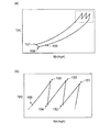
- It is a TS diagram of the Brayton cycle which a refrigerator has.
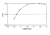
- It is a graph which shows the relationship between the compression ratio of the compressor in the refrigerator which concerns on a present Example, and a coefficient of performance ratio.
- It is a flowchart which shows the control content of the controller at the time of the fluctuation
- FIG. 1 is a schematic diagram conceptually showing the overall structure of a Brayton cycle refrigerator (hereinafter referred to as “refrigerator” as appropriate) 100 according to the present embodiment.
- FIG. 2 is a TS diagram of the Brayton cycle included in the refrigerator 100, where the vertical axis indicates the temperature T [K] and the horizontal axis indicates the entropy S [KJ / kgK].
- FIG. 2B is an enlarged view of a region surrounded by a broken line in FIG.
- a compressor 102 that compresses the refrigerant, a heat exchanger 103 that cools the compressed refrigerant by heat exchange with cooling water, and a refrigerant after cooling are expanded on a circulation path 101 through which the refrigerant flows.
- the expansion unit 104 that performs the heat exchange between the refrigerant and the cooling target, the cooling unit 105 that includes the heat exchanger, and the cold heat recovery heat exchanger 106 that collects the cold heat of the refrigerant are sequentially provided.
- a counter-current heat exchanger type Brayton cycle is formed by the refrigeration cycle.
- a superconducting device (not shown) using a superconductor in a cryogenic state is a cooling target.
- liquid nitrogen is used as a secondary refrigerant that exchanges heat with the refrigerant used in the refrigerator 100 in the cooling unit 105 (in FIG. 1, the liquid nitrogen that is the refrigerant among the objects to be cooled is Only the circulation path 150 that circulates is shown).
- the liquid nitrogen flowing through the circulation path 150 heated by the heat load of the superconducting equipment is cooled by exchanging heat with the refrigerant flowing through the circulation path 101 cooled by the refrigerator 100.
- a temperature sensor 160 that is a thermal load detecting means for detecting a thermal load to be cooled.
- the kind of gas may be selected suitably according to cooling temperature etc., for example, when helium, neon, hydrogen, nitrogen, air, a hydrocarbon etc. are used. Good.
- the refrigerator 100 includes a plurality of compressors 102a, 102b, 102c and heat exchangers 103a, 103b, 103c on a circulation path 101.
- the heat exchangers 103a, 103b, and 103c are provided on the downstream side of the compressors 102a, 102b, and 102c, respectively, and can cool the refrigerant that has been heated by adiabatic compression by exchanging heat with cooling water. ing.
- the refrigerant flowing in the circulation path 101 is first adiabatically compressed by the compressor 102a on the most upstream side and the temperature rises (corresponding to reference numeral 151 in FIG. 2B), and then the heat exchanger 103a provided on the downstream side. Is cooled by exchanging heat with cooling water (corresponding to reference numeral 152 in FIG. 2B). Then, after the refrigerant is adiabatically compressed again by the compressor 102b and the temperature rises (corresponding to the reference numeral 153 in FIG. 2B), heat is exchanged with cooling water in the heat exchanger 103b provided on the downstream side. It is cooled (corresponding to reference numeral 154 in FIG. 2B).
- the refrigerant is adiabatically compressed again by the compressor 102c and the temperature rises (corresponding to reference numeral 155 in FIG. 2b), the refrigerant is cooled by exchanging heat with cooling water in the heat exchanger 103c provided on the downstream side. (Corresponding to reference numeral 156 in FIG. 2B).
- efficiency is improved by repeating adiabatic compression by the compressor 102 and cooling by the heat exchanger 103 over a plurality of stages. That is, by repeating adiabatic compression and cooling over a plurality of stages, the Brayton cycle compression process is brought close to ideal isothermal compression.
- the temperature of the refrigerant that has passed through the heat exchanger 103c is further cooled by the cold recovery heat exchanger 106 (corresponding to reference numeral 157 in FIG. 2A), and then adiabatically expanded by the expander 104 to generate cold ( This corresponds to the reference numeral 158 in FIG.
- the refrigerator 100 having a single expander 104 is shown.
- a plurality of expanders may be provided in series with the circulation path 101. Good.
- the refrigerant discharged from the expander 104 is heat-exchanged with the liquid nitrogen flowing through the circulation path 150 in the superconducting device to be cooled in the cooling unit 105, and the temperature rises due to the thermal load (reference numeral in FIG. 2A). 159).
- the refrigerant whose temperature has been raised in the cooling unit 105 is introduced into the cold heat recovery heat exchanger 106, and the remaining cold heat is recovered by exchanging heat with the high-temperature compressed refrigerant that has passed through the heat exchanger 103c.
- transduced into the expander 104 can be reduced using the cold heat which remains in the refrigerant
- a Brayton cycle is configured using a plurality of rotating machines such as the compressor 102 and the expander 104.
- the two upstream compressors 102a and 102b are connected to both ends of the output shaft 108a of the electric motor 107a which is a common power source, respectively, thereby reducing the number of parts and laying in a small installation space.
- the compressor 102c and the expander 104 on the downstream side are also connected to both ends of the output shaft 108b of the electric motor 107b, which is a common power source, so that the number of parts can be reduced and installed in a small installation space.
- the power recovered by the expander 104 contributes to the compression power of the compressor 102c, thereby improving efficiency.
- FIG. 3 is a graph showing the relationship between the compression ratio of the compressor 102 and the coefficient of performance ratio (COP ratio) in the refrigerator 100 according to the present embodiment. According to this graph, it is analytically shown that the COP takes the maximum value when the compression ratio of the compressor 102 is about 1.40. According to the applicant's research, in order to set the compression ratio to about 1.40, it is optimal to set the number of stages of the compressor to “3” and the number of stages of the expander to “1”. It was found that
- the low-pressure line 109 through which the refrigerant before being compressed by the compressor 102 flows and the refrigerant after being compressed by the compressor flows.
- a buffer tank 111 is provided between the high pressure line 110.
- a first valve 112 that can control the amount of refrigerant flowing into the buffer tank 111 is provided on the inlet side (the high pressure line 110 side) of the buffer tank 111, and the outlet side (the low pressure line 109 side) of the buffer tank 111. ) Is provided with a second valve 113 capable of controlling the refrigerant outflow amount from the buffer tank 111.
- the first valve 112 and the second valve 113 are motor-operated valves whose opening degree can be adjusted based on a control signal from the controller 200 which is an example of the control means according to the present invention, and a circulation path constituting a Brayton cycle
- the refrigerant is allowed to flow in and out between 101 and the buffer tank 111.
- the controller 200 is a control unit that comprehensively controls the operation of the refrigerator 100, and controls each component of the refrigerator 100 based on the detection value of the temperature sensor 160 described above, thereby controlling the heat load to be cooled. Adjust the refrigerating capacity according to the fluctuation.
- the temperature sensor 160 on the circulation path 150 through which the secondary refrigerant flows, it is possible to quickly detect the fluctuation of the heat load on the cooling target, so the Brayton cycle refrigerator excellent in responsiveness. Is realized.
- a pressure sensor 170 for detecting the refrigerant pressure before being compressed by each compressor 102 is provided in the vicinity of the inlet of the compressor 102a disposed on the most upstream side.
- the detection value of the pressure sensor 170 corresponds to the flow rate of the refrigerant flowing through the circulation path 101, and is transmitted to the controller 200 and used for various controls, similarly to the detection value of the temperature sensor 160 described above. .
- FIG. 4 is a flowchart showing the control contents of the controller 200 when the heat load varies.
- the controller 200 determines whether there is a change in the thermal load on the cooling target based on the detection value of the temperature sensor 160 (step S101).
- step S101 YES
- the controller 200 calculates the rate of change of the thermal load and determines whether it is positive or negative (step S102).
- step S101 NO
- step S102 When the change rate of the thermal load is positive (step S102: YES), that is, when the thermal load is increasing, the controller 200 controls to open the second valve 113 with the first valve 112 closed. (Step S103). Then, due to the pressure difference between the buffer tank 111 and the low pressure line 109, the refrigerant stored in the buffer tank 111 is discharged to the low pressure line 109, and the refrigerant flow rate (pressure) flowing through the Brayton cycle increases. . As a result, the cooling capacity of the refrigerator 100 is adjusted to increase as the heat load to be cooled increases.
- step S102 when the rate of change of the thermal load is negative (step S102: NO), that is, when the thermal load is decreasing, the controller 200 opens the first valve 112 with the second valve 113 closed. Control (step S104). Then, due to the pressure difference between the high pressure line 110 and the buffer tank 111, a part of the refrigerant flowing through the high pressure line 110 is introduced into the buffer tank 111, and the refrigerant flow rate (pressure) flowing through the circulation path 101 is reduced. As a result, the cooling capacity of the refrigerator 100 is adjusted to be lowered according to the decrease in the heat load to be cooled.
- first valve 112 and the second valve 113 preferably use motor-operated valves because the opening degree needs to be adjusted during such flow rate control.
- the opening degree control of the first valve 112 and the second valve 113 by the controller 200 is performed so that, for example, the flow rate of refrigerant flowing through the circulation path 101 becomes a target flow rate corresponding to the rate of change of the thermal load detected by the temperature sensor 160. It is good to control.
- the target flow rate at this time for example, the relationship between the target opening degree of each valve corresponding to the target flow rate and the rate of change of the detected value of the temperature sensor 160 is stored in a storage unit such as a memory in advance as a map. It is preferable to control the opening degree of the valve in light of the actually measured value.
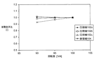
- FIG. 5 is a graph showing the relationship between the detection value of the pressure sensor 170 in the refrigerator 100 according to the present embodiment and the adiabatic efficiency ratio in each compressor 102 and the expander 104
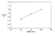
- FIG. 6 is the detection of the pressure sensor 170. It is a graph which shows the relationship between a value and a coefficient of performance (COP). 5 and 6 show the results of calculating the adiabatic efficiency ratio and COP based on the detected value of the pressure sensor 170 being 170 kPa.
- COP coefficient of performance
- FIGS. 7 and 8 show the relationship between the rotational speed, the adiabatic efficiency ratio, and the coefficient of performance (COP) when the refrigerating capacity is adjusted only by controlling the rotational speed of the compressor 102 and the expander 104 as in the prior art. It is a graph which shows. That is, FIG. 7 and FIG. 8 are comparative examples showing the case where the conventional rotational speed control is performed. 7 and 8 show the calculation results of the adiabatic efficiency ratio and the COP based on the rotation speed of 100%. In this case, as shown in FIG. 7, the adiabatic efficiency ratio in the rotating machine also decreases with the fluctuation of the rotational speed, and this tendency is particularly noticeable in the expander 104. Further, the expansion ratio also decreases as the rotational speed varies. As a result, as shown in FIG. 8, COP is reduced, and the refrigeration performance of the refrigerator is reduced.
- COP coefficient of performance
- the circulation path 101 is adjusted by adjusting the opening degree of the first valve 112 and the second valve 113 when a change in the thermal load is detected in the cooling target.
- Refrigeration capacity is controlled by changing the flow rate of refrigerant flowing through
- the mass flow rate is changed while keeping the volume flow rate of the refrigerant constant, so that there is no fluctuation in other control parameters such as pressure ratio and temperature, so that it is quick against fluctuations in heat load. Responsiveness can be obtained.
- the heat insulation efficiency of the expander which is a concern in the conventional rotational speed control, is not reduced, so that the refrigeration capacity can be kept constant.
- the buffer tank 111 is provided between the low pressure line 109 and the high pressure line 110 having a pressure difference. Therefore, the refrigerant can be introduced into the buffer tank 111 based on the pressure difference between the buffer tank 111 and the high pressure line 110 by opening and closing the first valve 112 provided on the high pressure line 110. On the other hand, by opening and closing the second valve 113 provided on the low pressure line 109, the refrigerant can be discharged from the buffer tank 111 based on the pressure difference between the buffer tank 111 and the low pressure line 109. As described above, the flow rate control by the buffer tank 111 does not require external power supply, and thus is excellent in energy efficiency.
- the buffer tank 111 is provided between a high-pressure line 110 through which the refrigerant is discharged from the compressor 102c arranged on the most downstream side and a low-pressure line 109 that supplies the refrigerant to the compressor 102a arranged on the most upstream side.
- a large pressure difference can be secured, so that the refrigerant can be easily introduced into and discharged from the buffer tank 111 by opening / closing control of the first valve 112 and the second valve 113.
- the high-pressure line 110 to which the buffer tank 111 is connected is branched from between the compressor 102 c and the cold heat recovery heat exchanger 106.
- the refrigerating capacity can be improved by precooling the high-temperature refrigerant supplied to the expander 104 using the cold heat remaining in the refrigerant after cooling the object to be cooled in the cooling unit 105.
- the refrigerant flow into the cooling unit 105 is reduced by branching from the upstream side of the cold recovery heat exchanger 106 and introducing the refrigerant into the buffer tank 111. Cooling of the refrigerant by the cold heat recovery heat exchanger 106 can be obtained more effectively.
- a bypass line 114 that bypasses the buffer tank 111 from the high pressure line 110 and connects to the low pressure line 109 is provided.
- a third valve 115 is provided. The third valve 115 is switched to an open state when the refrigerator 100 is started based on a control signal from the controller 200, so that the compressor 102 and the expander 104 are pre-cooled by operating at a high speed, and smooth. Allow cooling. In addition, it is good to perform such high rotation operation at the time of a start within the tolerance
- the third valve 115 is controlled to open so that the high pressure line 110 is changed to the low pressure line 109.
- the surging of the compressor 102 during pre-cooling can be prevented by releasing the refrigerant (bypassing the buffer tank 111) and securing the flow rate of the refrigerant.
- the second temperature sensor 180 is provided near the inlet of the expander 104, and the controller 200 determines that the possibility of surging is high based on the detection value of the temperature sensor 180.
- the third valve 115 may be automatically controlled to open.
- the opening degree adjustment by the controller 200 is also necessary for the third valve 115 as described above, it is preferable to use an electric valve.
- a second bypass line 116 that branches from between the compressor 102 b and the compressor 102 c in the circulation path 101 to the buffer tank 111 is provided, and a fourth valve 117 is provided on the second bypass line 116. Is provided. If any compressor 102 stops due to a malfunction in a control system such as a rotating machine such as the compressor 102 or the expander 104 or an inverter (not shown) for supplying power to the rotating machine, the Brayton There is a possibility that the flow rate of the refrigerant flowing through the cycle is reduced, and surging occurs in the other compressors 102 as well.
- surging can be prevented by releasing the refrigerant to the buffer tank 111 by controlling the opening of the fourth valve 117 by the controller 200.
- opening / closing control of the fourth valve 117 is performed by, for example, monitoring the rotation speed of the compressor 102 and the expander 104 and the output of various control systems such as an inverter by a sensor (not shown) in the controller 200. It is preferable to perform control so as to determine that surging has occurred when a decrease in the rotation speed or an error signal is detected, and control to open the fourth valve 117.
- the fourth valve 117 is preferably an electromagnetic valve because it requires a quick response to the opening command from the controller 200. Furthermore, a solenoid valve 118 is provided from the high pressure line 110 to the buffer tank 111, and is opened and closed based on a control signal from the controller 200, so that if any abnormality occurs, the refrigerant flowing through the high pressure line 110 is supplied to the buffer tank 111. You may comprise so that it may escape.
- the first to fourth valves described above allow the refrigerant flowing in the circulation path 101 to escape to the buffer tank 111 by opening and closing when an emergency such as an abnormality occurs in the refrigerator 100, for example. It may be. Thereby, since the unintended rise of the refrigerant pressure in the circulation path 101 and the surging in the compressor 102 can be avoided in advance, the refrigerator 100 having excellent safety can be realized.
- the flow rate and pressure ratio of the refrigerant may be monitored by a sensor to control the opening degree of various valves.
- stepless control of the rotation speed is preferable.
- the apparatus configuration becomes complicated in order to perform stepless control of the rotational speed.
- surging can be avoided by controlling the flow rate of the refrigerant, so that safety can be improved while simplifying the device configuration.
- the buffer tank 111 may also be used for absorbing the volume change of the refrigerant during the cycle when the refrigerator 100 is stopped.
- the refrigerant flow rate control using the buffer tank 11 in the present invention has been conventionally used. Since it can be realized by using a tank together, it is advantageous in terms of cost.
- the refrigerator 100 according to the present embodiment can function by opening / closing control of various valves, component deterioration due to friction or the like hardly occurs. Therefore, the apparatus life is long, and durability, reliability, and soundness can be ensured over a long period of time.
- the valve opening / closing operation can be easily performed even in an extremely low temperature state, the valve can be introduced into a system used in a severe temperature environment such as a superconductor device.
- adiabatic compression is performed in the compression step in the Brayton cycle
- the present invention may also be applied to a so-called Ericsson cycle in which adiabatic compression is replaced with isothermal compression.
- the compression heating by the compressor 102 and the cooling by the heat exchanger 103 are repeatedly performed in multiple stages.
- substantially isothermal compression can be realized. Therefore, the case where it can be substantially regarded as an Ericsson cycle refrigerator by increasing the number of compression stages of the Brayton cycle refrigerator according to the present embodiment is also included in the scope of the present invention.
- the refrigerator using the Brayton cycle has been described.
- the present invention can be similarly applied to a heat pump device using the Brayton cycle.
- the present invention can be used for a Brayton cycle refrigerator that can control the cooling capacity with respect to the thermal load fluctuation in the cooling target.
Landscapes
- Engineering & Computer Science (AREA)
- Mechanical Engineering (AREA)
- General Engineering & Computer Science (AREA)
- Physics & Mathematics (AREA)
- Thermal Sciences (AREA)
- Chemical & Material Sciences (AREA)
- Combustion & Propulsion (AREA)
- Control Of Positive-Displacement Pumps (AREA)
- Devices That Are Associated With Refrigeration Equipment (AREA)
- Applications Or Details Of Rotary Compressors (AREA)
- Air Conditioning Control Device (AREA)
- Compression-Type Refrigeration Machines With Reversible Cycles (AREA)
Abstract
Description
尚、冷凍機に用いられるブレイトンサイクルは、熱機関として用いられるブレイトンサイクルに対して「逆ブレイトンサイクル」と呼ばれるが、本明細書は単に「ブレイトンサイクル」と称することとする(「超電導・低温工学ハンドブック」1993オーム社(社団法人低温工学協会編)を参照)。
この態様によれば、高圧ラインと低圧ラインとの間の圧力差を大きく確保できるので、第1のバルブ及び第2のバルブの開閉制御によって、バッファタンクへの冷媒の導入・排出による流量制御を容易に行うことができる。
この態様によれば、冷熱回収熱交換器において冷却対象を冷却後の冷媒に残った冷熱を用いて、膨張機に供給される高温の冷媒を予冷することで冷凍能力を向上できる。バッファタンクに冷媒を導入して流量制御する場合、冷熱回収熱交換器の上流側から分岐してバッファタンクに冷媒を導入することで、冷熱回収熱交換器に供給される冷媒流量が少なくなるので、冷熱回収熱交換器による冷媒の冷却をより効果的に発揮することができる。
この態様によれば、冷却対象において急激な熱負荷変動が生じた場合には、上述のバルブの開度調整による冷媒の流量制御に先じて、圧縮機及び膨張機の回転数を制御することにより、大きな熱負荷変動に対しても良好な応答性が得えられる。
この態様によれば、冷却対象における熱負荷の変動を検出するための熱負荷検出手段を二次冷媒が流れるライン上に設けられた温度センサとすることで、冷却対象における熱負荷の変動を迅速に検出することができるので、応答性に優れたブレイトンサイクル冷凍機を実現できる。
この態様によれば、第1から第3の圧縮機をそれぞれ循環経路上に直列に設けることによって多段圧縮が可能に構成されている。特に第1の圧縮機は第2の圧縮機と共に第1の電動モータの出力軸上に連結されることにより、圧縮機毎に動力源を設ける場合に比べて構成をシンプル化できる。第3の圧縮機もまた、膨張機と共に第2の電動モータの出力軸上に連結されることにより構成をシンプル化できることに加えて膨張機で回収した動力が第3の圧縮機の圧縮動力に寄与することによって、効率化を図ることができる。
そして、二次冷媒が流れる循環経路150上には、冷却対象の熱負荷を検出する熱負荷検出手段である温度センサ160が設けられている。
尚、図1の例では、単一の膨張機104を有する冷凍機100を示しているが、圧縮機102と同様に、循環経路101に対して直列に複数の膨張機が設けられていてもよい。
上流側の2つの圧縮機102a及び102bは、共通の動力源である電動機107aの出力軸108aの両端にそれぞれ連結されることによって、部品填数を削減し、少ない設置スペースに敷設可能に構成されている。下流側の圧縮機102c及び膨張機104もまた、共通の動力源である電動機107bの出力軸108bの両端にそれぞれ連結されることによって部品填数を削減し、少ない設置スペースに敷設可能に構成されているが、これに加えて、膨張機104で回収した動力が圧縮機102cの圧縮動力に寄与することによって、効率化が図られている。
本実施例では特に、温度センサ160を二次冷媒が流れる循環経路150上に設けることによって、冷却対象における熱負荷の変動を迅速に検出することができるので、応答性に優れたブレイトンサイクル冷凍機を実現している。
これらのグラフに示されているように、本実施例に係る冷凍機100では、各圧縮機102で圧縮される前の冷媒圧力が変化した場合であっても、断熱効率比と成績係数(COP)とは共に略一定に維持され、変化しないとの結果が得られた。
この場合、図7に示すように、回転数の変動に伴って回転機における断熱効率比も低下しており、特に膨張機104においてその傾向が顕著に現れている。また、回転数の変動に伴い、膨張比も低下する。その結果、図8に示すようにCOPが低下しており、冷凍機の冷凍性能が低下してしまっている。
尚、このような始動時の高回転運転は、冷凍機100に用いられる熱交換器等の冷却速度の許容範囲内で行うとよい。
Claims (6)
- 冷媒ライン上にて直列接続された多段式の圧縮機によって圧縮された冷媒を用いて冷熱を発生させるブレイトンサイクルにより冷媒を冷却するブレイトンサイクル冷凍機であって、
冷却対象の熱負荷を検出する熱負荷検出手段と、
前記圧縮機で圧縮される前の冷媒が流れる低圧ラインと前記圧縮機で圧縮された後の冷媒が流れる高圧ラインとの間に設けられたバッファタンクと、
前記バッファタンクの入口側に設けられることにより、前記バッファタンクへの冷媒流入量を制御可能な第1のバルブと、
前記バッファタンクの出口側に設けられることにより、前記バッファタンクからの冷媒流出量を制御可能な第2のバルブと、
前記第1のバルブ及び前記第2のバルブの開度を制御する制御手段と、
を備え、
前記制御手段は、前記熱負荷検出手段によって前記冷却対象において熱負荷の変動が検出された場合に、前記第1のバルブ及び前記第2のバルブの開度を調整することにより、前記ブレイトンサイクルを流れる冷媒流量を変化させることを特徴とするブレイトンサイクル冷凍機。 - 前記高圧ラインは、最下流側に配置された前記圧縮機から冷媒が排出されるラインであり、
前記低圧ラインは、最上流側に配置された前記圧縮機に冷媒を供給するラインであることを特徴とする請求項1に記載のブレイトンサイクル冷凍機。 - 前記圧縮機で圧縮された冷媒と冷却対象を冷却後の冷媒とを熱交換する冷熱回収熱交換器を備え、
前記高圧ラインは前記圧縮機と前記冷熱回収熱交換器との間から分岐されていることを特徴とする請求項2に記載のブレイトンサイクル冷凍機。 - 前記制御手段は、前記熱負荷検出手段により検出された熱負荷の変化率が予め設定された所定値より大きい場合、前記圧縮機及び膨張機の回転数を制御した後に、前記第1のバルブ及び前記第2のバルブの開度を調整することを特徴とする請求項1から3のいずれか一項に記載のブレイトンサイクル冷凍機。
- 前記ブレイトンサイクルの冷却部は、熱交換器を介して冷却対象を循環する二次冷媒を冷却し、
前記熱負荷検出手段は、前記二次冷媒が流れるライン上に設けられた温度センサであることを特徴とする請求項1から4のいずれか一項に記載のブレイトンサイクル冷凍機。 - 前記多段式の圧縮機は、上流側から順に第1の圧縮機、第2の圧縮機及び第3の圧縮機が直列接続されて構成されており、
前記第1の圧縮機及び前記第2の圧縮機は、第1の電動モータの出力軸上に連結されており、
前記第3の圧縮機及び前記膨張機は、第2の電動モータの出力軸上に連結されていることを特徴とする請求項1から5のいずれか一項に記載のブレイトンサイクル冷凍機。
Priority Applications (8)
| Application Number | Priority Date | Filing Date | Title |
|---|---|---|---|
| CN201480031067.XA CN105247299B (zh) | 2013-05-31 | 2014-03-20 | 布雷顿循环冷冻机 |
| ES14804125.4T ES2640631T3 (es) | 2013-05-31 | 2014-03-20 | Dispositivo de refrigeración de ciclo Brayton |
| KR1020157022659A KR101735623B1 (ko) | 2013-05-31 | 2014-03-20 | 브레이턴 사이클 냉동기 |
| RU2015150778A RU2631841C2 (ru) | 2013-05-31 | 2014-03-20 | Устройство охлаждения на основе цикла брайтона |
| US14/773,798 US9863669B2 (en) | 2013-05-31 | 2014-03-20 | Brayton cycle type refrigerating apparatus |
| EP16197194.0A EP3153795B1 (en) | 2013-05-31 | 2014-03-20 | Brayton cycle refrigerating apparatus |
| JP2015519709A JP5985746B2 (ja) | 2013-05-31 | 2014-03-20 | ブレイトンサイクル冷凍機 |
| EP14804125.4A EP2940406B1 (en) | 2013-05-31 | 2014-03-20 | Brayton cycle refrigeration device |
Applications Claiming Priority (2)
| Application Number | Priority Date | Filing Date | Title |
|---|---|---|---|
| JP2013116116 | 2013-05-31 | ||
| JP2013-116116 | 2013-05-31 |
Publications (1)
| Publication Number | Publication Date |
|---|---|
| WO2014192382A1 true WO2014192382A1 (ja) | 2014-12-04 |
Family
ID=51988426
Family Applications (1)
| Application Number | Title | Priority Date | Filing Date |
|---|---|---|---|
| PCT/JP2014/057679 Ceased WO2014192382A1 (ja) | 2013-05-31 | 2014-03-20 | ブレイトンサイクル冷凍機 |
Country Status (8)
| Country | Link |
|---|---|
| US (1) | US9863669B2 (ja) |
| EP (2) | EP2940406B1 (ja) |
| JP (1) | JP5985746B2 (ja) |
| KR (1) | KR101735623B1 (ja) |
| CN (1) | CN105247299B (ja) |
| ES (2) | ES2689656T3 (ja) |
| RU (1) | RU2631841C2 (ja) |
| WO (1) | WO2014192382A1 (ja) |
Cited By (3)
| Publication number | Priority date | Publication date | Assignee | Title |
|---|---|---|---|---|
| WO2018155209A1 (ja) * | 2017-02-24 | 2018-08-30 | 株式会社前川製作所 | 圧縮機用ピストン、圧縮機及びヒートポンプユニット |
| WO2022153944A1 (ja) * | 2021-01-14 | 2022-07-21 | 大陽日酸株式会社 | 冷凍機の制御方法、冷凍機の制御プログラム及び冷凍機 |
| WO2022191166A1 (ja) | 2021-03-10 | 2022-09-15 | 大陽日酸株式会社 | 冷凍機 |
Families Citing this family (30)
| Publication number | Priority date | Publication date | Assignee | Title |
|---|---|---|---|---|
| US10094219B2 (en) | 2010-03-04 | 2018-10-09 | X Development Llc | Adiabatic salt energy storage |
| WO2014052927A1 (en) | 2012-09-27 | 2014-04-03 | Gigawatt Day Storage Systems, Inc. | Systems and methods for energy storage and retrieval |
| US10415857B2 (en) * | 2015-05-01 | 2019-09-17 | Mayekawa Mfg. Co., Ltd. | Refrigerator and operation method for refrigerator |
| US10082045B2 (en) * | 2016-12-28 | 2018-09-25 | X Development Llc | Use of regenerator in thermodynamic cycle system |
| US11053847B2 (en) | 2016-12-28 | 2021-07-06 | Malta Inc. | Baffled thermoclines in thermodynamic cycle systems |
| US10233787B2 (en) | 2016-12-28 | 2019-03-19 | Malta Inc. | Storage of excess heat in cold side of heat engine |
| US10458284B2 (en) | 2016-12-28 | 2019-10-29 | Malta Inc. | Variable pressure inventory control of closed cycle system with a high pressure tank and an intermediate pressure tank |
| US10233833B2 (en) | 2016-12-28 | 2019-03-19 | Malta Inc. | Pump control of closed cycle power generation system |
| US10280804B2 (en) | 2016-12-29 | 2019-05-07 | Malta Inc. | Thermocline arrays |
| US10221775B2 (en) | 2016-12-29 | 2019-03-05 | Malta Inc. | Use of external air for closed cycle inventory control |
| US10082104B2 (en) | 2016-12-30 | 2018-09-25 | X Development Llc | Atmospheric storage and transfer of thermal energy |
| US10801404B2 (en) | 2016-12-30 | 2020-10-13 | Malta Inc. | Variable pressure turbine |
| US10436109B2 (en) | 2016-12-31 | 2019-10-08 | Malta Inc. | Modular thermal storage |
| EP4451551A3 (en) | 2018-01-11 | 2025-01-22 | Lancium Llc | Method and system for dynamic power delivery to a flexible datacenter using unutilized energy sources |
| CN109059347B (zh) * | 2018-06-19 | 2021-03-12 | 李华玉 | 第三类热驱动压缩式热泵 |
| CN111023620A (zh) * | 2018-10-09 | 2020-04-17 | 山东新华能节能科技有限公司 | 一种涡旋式空气源热泵双级系统 |
| WO2021097413A1 (en) | 2019-11-16 | 2021-05-20 | Malta Inc. | Pumped heat electric storage system |
| EP4080137A4 (en) * | 2019-12-18 | 2024-02-21 | Universitat Politècnica de València | METHOD AND APPARATUS FOR COOLING |
| BR112023002535A2 (pt) | 2020-08-12 | 2023-04-18 | Malta Inc | Sistema de armazenamento de energia térmica bombeada com ciclo de vapor |
| US11454167B1 (en) | 2020-08-12 | 2022-09-27 | Malta Inc. | Pumped heat energy storage system with hot-side thermal integration |
| US11396826B2 (en) | 2020-08-12 | 2022-07-26 | Malta Inc. | Pumped heat energy storage system with electric heating integration |
| US11486305B2 (en) | 2020-08-12 | 2022-11-01 | Malta Inc. | Pumped heat energy storage system with load following |
| US11480067B2 (en) | 2020-08-12 | 2022-10-25 | Malta Inc. | Pumped heat energy storage system with generation cycle thermal integration |
| US11286804B2 (en) | 2020-08-12 | 2022-03-29 | Malta Inc. | Pumped heat energy storage system with charge cycle thermal integration |
| EP4296477A3 (en) | 2020-08-12 | 2024-02-28 | Malta Inc. | Pumped heat energy storage system with modular turbomachinery |
| KR102341074B1 (ko) * | 2020-11-17 | 2021-12-20 | 주식회사 에프에스티 | 극저온 냉동기 |
| JP2022087598A (ja) * | 2020-12-01 | 2022-06-13 | 株式会社前川製作所 | 冷凍機及び冷凍機の予冷時の運転方法 |
| EP4430285A4 (en) | 2021-12-14 | 2025-11-26 | Malta Inc | PUMPED THERMAL ENERGY STORAGE SYSTEM INTEGRATED INTO A COAL-FIRED POWER GENERATION UNIT |
| EP4653680A1 (en) | 2024-05-09 | 2025-11-26 | SIT Technologies S.r.l. | Open brayton type reverse cycle for thermal recovery |
| CN119084799B (zh) * | 2024-09-27 | 2025-09-16 | 中国科学院理化技术研究所 | 一种基于逆布雷顿循环的低温高压储氢系统 |
Citations (5)
| Publication number | Priority date | Publication date | Assignee | Title |
|---|---|---|---|---|
| JPH05272357A (ja) * | 1992-03-27 | 1993-10-19 | Nippon Sanso Kk | 圧縮機及びその運転方法 |
| JPH09329034A (ja) | 1996-06-11 | 1997-12-22 | Ishikawajima Harima Heavy Ind Co Ltd | 閉サイクルガスタービン |
| JP2003148824A (ja) | 2001-11-13 | 2003-05-21 | Daikin Ind Ltd | 空気調和装置 |
| JP2011106755A (ja) * | 2009-11-18 | 2011-06-02 | Taiyo Nippon Sanso Corp | 極低温冷凍装置及びその運転方法 |
| JP2012251667A (ja) * | 2011-05-31 | 2012-12-20 | Mayekawa Mfg Co Ltd | 空気冷媒式冷凍装置のデフロスト方法及び装置 |
Family Cites Families (15)
| Publication number | Priority date | Publication date | Assignee | Title |
|---|---|---|---|---|
| US10303A (en) * | 1853-12-06 | Shower-sybinoke | ||
| GB487026A (en) | 1936-11-05 | 1938-06-14 | Bbc Brown Boveri & Cie | Improvements in compression heating and refrigerating apparatus |
| FR2349799A1 (fr) * | 1976-04-28 | 1977-11-25 | Abg Semca | Procede et dispositif de conditionnement de l'air d'une enceinte |
| GB1555522A (en) | 1976-08-06 | 1979-11-14 | Normalair Garrett Ltd | Environmental temperature control systems |
| US4175397A (en) | 1977-02-18 | 1979-11-27 | The Rovac Corporation | Closed loop air conditioning system including pressurization by blockage and aspiration |
| DE2834256C2 (de) | 1978-08-04 | 1985-05-23 | Messerschmitt-Bölkow-Blohm GmbH, 8012 Ottobrunn | Anordnung zur Klimatisierung von Luftfahrzeugkabinen |
| JP2873388B2 (ja) * | 1990-05-15 | 1999-03-24 | 日本酸素株式会社 | 冷凍機及びその冷凍能力の調整方法 |
| US5524442A (en) * | 1994-06-27 | 1996-06-11 | Praxair Technology, Inc. | Cooling system employing a primary, high pressure closed refrigeration loop and a secondary refrigeration loop |
| US6209338B1 (en) * | 1998-07-15 | 2001-04-03 | William Bradford Thatcher, Jr. | Systems and methods for controlling refrigerant charge |
| US7185501B2 (en) | 2004-12-16 | 2007-03-06 | General Electric Company | Cryogenic cooling system and method with backup cold storage device |
| RU2295097C1 (ru) | 2005-09-23 | 2007-03-10 | Грамш Владимир Анатольевич | Способ охлаждения воздуха и устройство для осуществления этого способа |
| JP2009121786A (ja) | 2007-11-19 | 2009-06-04 | Ihi Corp | 極低温冷凍装置とその制御方法 |
| FR2943768B1 (fr) | 2009-03-24 | 2011-04-29 | Commissariat Energie Atomique | Systeme cryogenique pour le refroidissement d'un consommateur presentant une charge thermique variable dans le temps. |
| US9546647B2 (en) | 2011-07-06 | 2017-01-17 | Sumitomo (Shi) Cryogenics Of America Inc. | Gas balanced brayton cycle cold water vapor cryopump |
| JP5599766B2 (ja) | 2011-09-30 | 2014-10-01 | 住友重機械工業株式会社 | 極低温冷凍機 |
-
2014
- 2014-03-20 ES ES16197194.0T patent/ES2689656T3/es active Active
- 2014-03-20 ES ES14804125.4T patent/ES2640631T3/es active Active
- 2014-03-20 WO PCT/JP2014/057679 patent/WO2014192382A1/ja not_active Ceased
- 2014-03-20 RU RU2015150778A patent/RU2631841C2/ru active
- 2014-03-20 CN CN201480031067.XA patent/CN105247299B/zh active Active
- 2014-03-20 US US14/773,798 patent/US9863669B2/en active Active
- 2014-03-20 EP EP14804125.4A patent/EP2940406B1/en active Active
- 2014-03-20 EP EP16197194.0A patent/EP3153795B1/en active Active
- 2014-03-20 KR KR1020157022659A patent/KR101735623B1/ko active Active
- 2014-03-20 JP JP2015519709A patent/JP5985746B2/ja active Active
Patent Citations (5)
| Publication number | Priority date | Publication date | Assignee | Title |
|---|---|---|---|---|
| JPH05272357A (ja) * | 1992-03-27 | 1993-10-19 | Nippon Sanso Kk | 圧縮機及びその運転方法 |
| JPH09329034A (ja) | 1996-06-11 | 1997-12-22 | Ishikawajima Harima Heavy Ind Co Ltd | 閉サイクルガスタービン |
| JP2003148824A (ja) | 2001-11-13 | 2003-05-21 | Daikin Ind Ltd | 空気調和装置 |
| JP2011106755A (ja) * | 2009-11-18 | 2011-06-02 | Taiyo Nippon Sanso Corp | 極低温冷凍装置及びその運転方法 |
| JP2012251667A (ja) * | 2011-05-31 | 2012-12-20 | Mayekawa Mfg Co Ltd | 空気冷媒式冷凍装置のデフロスト方法及び装置 |
Non-Patent Citations (1)
| Title |
|---|
| "Handbook of Superconductivity and Cryogenic Engineering", 1993, OHMSHA |
Cited By (6)
| Publication number | Priority date | Publication date | Assignee | Title |
|---|---|---|---|---|
| WO2018155209A1 (ja) * | 2017-02-24 | 2018-08-30 | 株式会社前川製作所 | 圧縮機用ピストン、圧縮機及びヒートポンプユニット |
| JP2018138780A (ja) * | 2017-02-24 | 2018-09-06 | 株式会社前川製作所 | 圧縮機用ピストン、圧縮機及びヒートポンプユニット |
| WO2022153944A1 (ja) * | 2021-01-14 | 2022-07-21 | 大陽日酸株式会社 | 冷凍機の制御方法、冷凍機の制御プログラム及び冷凍機 |
| JP2022109068A (ja) * | 2021-01-14 | 2022-07-27 | 大陽日酸株式会社 | 冷凍機の制御方法、冷凍機の制御プログラム及び冷凍機 |
| WO2022191166A1 (ja) | 2021-03-10 | 2022-09-15 | 大陽日酸株式会社 | 冷凍機 |
| US12078401B2 (en) | 2021-03-10 | 2024-09-03 | Taiyo Nippon Sanso Corporation | Refrigeration machine |
Also Published As
| Publication number | Publication date |
|---|---|
| KR20160016748A (ko) | 2016-02-15 |
| EP3153795B1 (en) | 2018-09-05 |
| ES2640631T3 (es) | 2017-11-03 |
| EP2940406A4 (en) | 2016-06-15 |
| RU2015150778A (ru) | 2017-07-05 |
| ES2689656T3 (es) | 2018-11-15 |
| JP5985746B2 (ja) | 2016-09-06 |
| US9863669B2 (en) | 2018-01-09 |
| JPWO2014192382A1 (ja) | 2017-02-23 |
| CN105247299B (zh) | 2017-08-04 |
| EP3153795A1 (en) | 2017-04-12 |
| US20160018134A1 (en) | 2016-01-21 |
| EP2940406B1 (en) | 2017-08-16 |
| KR101735623B1 (ko) | 2017-05-15 |
| RU2631841C2 (ru) | 2017-09-26 |
| CN105247299A (zh) | 2016-01-13 |
| EP2940406A1 (en) | 2015-11-04 |
Similar Documents
| Publication | Publication Date | Title |
|---|---|---|
| JP5985746B2 (ja) | ブレイトンサイクル冷凍機 | |
| US20100275616A1 (en) | Cryogenic refrigerator and control method therefor | |
| EP2693136A1 (en) | Expansion valve control device, heat source machine, and expansion valve control method | |
| CN113137691A (zh) | 磁悬浮空调机组的控制方法 | |
| CN112594866A (zh) | 一种多联机水力模块防冻控制系统及其控制方法 | |
| US20130125573A1 (en) | Heat source system and control method therefor | |
| JP6422590B2 (ja) | 熱源システム | |
| KR20140022619A (ko) | 공기조화기 및 공기조화기의 제어방법 | |
| JP6316452B2 (ja) | 冷凍サイクル装置 | |
| US20230417465A1 (en) | Refrigerator and operation method during precooling of refrigerator | |
| JP7080801B2 (ja) | ターボ冷凍機 | |
| JP2008057874A (ja) | 冷凍サイクル装置 | |
| JP2019095079A (ja) | 高温超電導電力機器用冷却システム及びその運転方法 | |
| JP5485022B2 (ja) | 低温蓄熱冷却装置 | |
| JP2014001916A (ja) | 冷凍サイクル装置 | |
| JP2013217602A (ja) | 熱源機、冷凍空調装置、制御装置 | |
| JP5412073B2 (ja) | 熱源システムおよびその制御方法 | |
| JP2021188881A (ja) | 冷凍システム及び冷凍システムの制御方法 | |
| KR102532023B1 (ko) | 초임계 냉각 시스템 및 그 제어방법 | |
| JP2014134321A (ja) | 複合型空調システム | |
| JP6438717B2 (ja) | 冷却システム | |
| JPH11148735A (ja) | ヘリウム冷凍液化機の運転制御装置 | |
| JP2023079334A (ja) | 冷蔵庫 | |
| JPH05322344A (ja) | 冷凍装置におけるタービン式膨張機の運転状態制御方法及び装置 | |
| JPWO2014109079A1 (ja) | 複数温度システム |
Legal Events
| Date | Code | Title | Description |
|---|---|---|---|
| 121 | Ep: the epo has been informed by wipo that ep was designated in this application |
Ref document number: 14804125 Country of ref document: EP Kind code of ref document: A1 |
|
| ENP | Entry into the national phase |
Ref document number: 2015519709 Country of ref document: JP Kind code of ref document: A |
|
| REEP | Request for entry into the european phase |
Ref document number: 2014804125 Country of ref document: EP |
|
| WWE | Wipo information: entry into national phase |
Ref document number: 2014804125 Country of ref document: EP |
|
| ENP | Entry into the national phase |
Ref document number: 20157022659 Country of ref document: KR Kind code of ref document: A |
|
| WWE | Wipo information: entry into national phase |
Ref document number: 14773798 Country of ref document: US |
|
| NENP | Non-entry into the national phase |
Ref country code: DE |
|
| ENP | Entry into the national phase |
Ref document number: 2015150778 Country of ref document: RU Kind code of ref document: A |