WO2014192169A1 - 照明器具 - Google Patents
照明器具 Download PDFInfo
- Publication number
- WO2014192169A1 WO2014192169A1 PCT/JP2013/072432 JP2013072432W WO2014192169A1 WO 2014192169 A1 WO2014192169 A1 WO 2014192169A1 JP 2013072432 W JP2013072432 W JP 2013072432W WO 2014192169 A1 WO2014192169 A1 WO 2014192169A1
- Authority
- WO
- WIPO (PCT)
- Prior art keywords
- reflector
- end side
- base end
- led
- side part
- Prior art date
Links
Images

Classifications
-
- F—MECHANICAL ENGINEERING; LIGHTING; HEATING; WEAPONS; BLASTING
- F21—LIGHTING
- F21V—FUNCTIONAL FEATURES OR DETAILS OF LIGHTING DEVICES OR SYSTEMS THEREOF; STRUCTURAL COMBINATIONS OF LIGHTING DEVICES WITH OTHER ARTICLES, NOT OTHERWISE PROVIDED FOR
- F21V7/00—Reflectors for light sources
- F21V7/0083—Array of reflectors for a cluster of light sources, e.g. arrangement of multiple light sources in one plane
-
- F—MECHANICAL ENGINEERING; LIGHTING; HEATING; WEAPONS; BLASTING
- F21—LIGHTING
- F21V—FUNCTIONAL FEATURES OR DETAILS OF LIGHTING DEVICES OR SYSTEMS THEREOF; STRUCTURAL COMBINATIONS OF LIGHTING DEVICES WITH OTHER ARTICLES, NOT OTHERWISE PROVIDED FOR
- F21V17/00—Fastening of component parts of lighting devices, e.g. shades, globes, refractors, reflectors, filters, screens, grids or protective cages
- F21V17/002—Fastening of component parts of lighting devices, e.g. shades, globes, refractors, reflectors, filters, screens, grids or protective cages with provision for interchangeability, i.e. component parts being especially adapted to be replaced by another part with the same or a different function
-
- F—MECHANICAL ENGINEERING; LIGHTING; HEATING; WEAPONS; BLASTING
- F21—LIGHTING
- F21V—FUNCTIONAL FEATURES OR DETAILS OF LIGHTING DEVICES OR SYSTEMS THEREOF; STRUCTURAL COMBINATIONS OF LIGHTING DEVICES WITH OTHER ARTICLES, NOT OTHERWISE PROVIDED FOR
- F21V23/00—Arrangement of electric circuit elements in or on lighting devices
- F21V23/02—Arrangement of electric circuit elements in or on lighting devices the elements being transformers, impedances or power supply units, e.g. a transformer with a rectifier
-
- F—MECHANICAL ENGINEERING; LIGHTING; HEATING; WEAPONS; BLASTING
- F21—LIGHTING
- F21V—FUNCTIONAL FEATURES OR DETAILS OF LIGHTING DEVICES OR SYSTEMS THEREOF; STRUCTURAL COMBINATIONS OF LIGHTING DEVICES WITH OTHER ARTICLES, NOT OTHERWISE PROVIDED FOR
- F21V7/00—Reflectors for light sources
- F21V7/04—Optical design
-
- F—MECHANICAL ENGINEERING; LIGHTING; HEATING; WEAPONS; BLASTING
- F21—LIGHTING
- F21V—FUNCTIONAL FEATURES OR DETAILS OF LIGHTING DEVICES OR SYSTEMS THEREOF; STRUCTURAL COMBINATIONS OF LIGHTING DEVICES WITH OTHER ARTICLES, NOT OTHERWISE PROVIDED FOR
- F21V7/00—Reflectors for light sources
- F21V7/10—Construction
-
- F—MECHANICAL ENGINEERING; LIGHTING; HEATING; WEAPONS; BLASTING
- F21—LIGHTING
- F21V—FUNCTIONAL FEATURES OR DETAILS OF LIGHTING DEVICES OR SYSTEMS THEREOF; STRUCTURAL COMBINATIONS OF LIGHTING DEVICES WITH OTHER ARTICLES, NOT OTHERWISE PROVIDED FOR
- F21V29/00—Protecting lighting devices from thermal damage; Cooling or heating arrangements specially adapted for lighting devices or systems
- F21V29/50—Cooling arrangements
- F21V29/70—Cooling arrangements characterised by passive heat-dissipating elements, e.g. heat-sinks
- F21V29/74—Cooling arrangements characterised by passive heat-dissipating elements, e.g. heat-sinks with fins or blades
- F21V29/76—Cooling arrangements characterised by passive heat-dissipating elements, e.g. heat-sinks with fins or blades with essentially identical parallel planar fins or blades, e.g. with comb-like cross-section
-
- F—MECHANICAL ENGINEERING; LIGHTING; HEATING; WEAPONS; BLASTING
- F21—LIGHTING
- F21Y—INDEXING SCHEME ASSOCIATED WITH SUBCLASSES F21K, F21L, F21S and F21V, RELATING TO THE FORM OR THE KIND OF THE LIGHT SOURCES OR OF THE COLOUR OF THE LIGHT EMITTED
- F21Y2105/00—Planar light sources
- F21Y2105/10—Planar light sources comprising a two-dimensional array of point-like light-generating elements
-
- F—MECHANICAL ENGINEERING; LIGHTING; HEATING; WEAPONS; BLASTING
- F21—LIGHTING
- F21Y—INDEXING SCHEME ASSOCIATED WITH SUBCLASSES F21K, F21L, F21S and F21V, RELATING TO THE FORM OR THE KIND OF THE LIGHT SOURCES OR OF THE COLOUR OF THE LIGHT EMITTED
- F21Y2115/00—Light-generating elements of semiconductor light sources
- F21Y2115/10—Light-emitting diodes [LED]
Definitions
- the present invention relates to a lighting fixture.
- Luminaires using multiple LEDs as light sources are widely known.
- the lighting fixture which provided the concave-surface reflective mirror in each of several LED and controlled light distribution is known (for example, patent document 1).
- the main light distribution is defined by the concave reflecting mirror. For this reason, it is difficult to change the light distribution appropriately according to the installation location, the purpose of illumination, and the like.
- This invention is made
- the present invention provides a lighting fixture in which a light source and a reflector having a reflecting surface having a rotational curved surface are housed in a fixture main body, wherein the reflector is a base end side and a tip end side of the reflecting surface. And at least the distal end of the base end side part protrudes from the instrument body.
- the present invention is characterized in that the above-mentioned lighting apparatus includes a coupling portion that couples a part on the proximal end side of the reflector and a part on the distal end side.
- the present invention provides the above-described lighting device, wherein the reflector has a plurality of reflecting surfaces connected by a connecting portion, and the coupling portion that inserts and couples the base-side part and the tip-side part, The connecting portion is provided.
- the present invention is characterized in that in the above-mentioned lighting fixture, a plurality of the reflectors are provided, and each of the reflectors is arranged inside the fixture body.
- the present invention provides the lighting apparatus, wherein the light source includes a light-emitting element and a light-emitting element substrate on which the light-emitting element is mounted, and is provided between a part on the base end side of the reflector and the light-emitting element substrate. It is characterized by providing a spacer.
- the present invention provides the lighting apparatus, wherein the spacer has a surface continuous with a reflection surface of a part on the proximal end side of the reflector, and the shape of the surface is defined as the reflection surface of the light emitting element substrate. It is characterized in that it matches the shape when extended to the side.
- the present invention is characterized in that, in the above-mentioned lighting apparatus, the reflector integrally includes a plurality of the reflecting surfaces arranged so that rotation axes thereof are parallel to each other.
- the present invention provides the above-described lighting fixture, further comprising a power supply box in which an electric circuit for supplying electric power to the light source is housed, and a plurality of radiating fins extending in one direction on a back surface of the luminaire body, A boss that supports the power supply box is erected in a space formed by removing a part of the power supply box with a gap between the radiating fin.
- the present invention is characterized in that in the above-mentioned lighting apparatus, at least one of the heat radiating fins is connected to the boss.
- the reflector is separable at the base end side and the tip end side of the reflecting surface, the tip end side is removed or used, or the tip end side has different reflection characteristics and light distribution characteristics.
- the orientation pattern of the reflecting surface of the reflector can be arbitrarily and easily changed by changing to.
- the tip of the base side part protrudes from the instrument body, the emitted light from the reflector is not shielded by the instrument body even when the tip side is removed from the reflector. Instrument efficiency is not reduced.
- the instrument body can reduce the depth in which the reflector is accommodated, the instrument body can be reduced in weight.
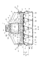
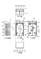
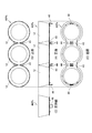
- FIG. 1A and 1B are diagrams showing an external configuration of an LED lighting apparatus according to an embodiment of the present invention.
- FIG. 1A is a front view
- FIG. 1B is a side view
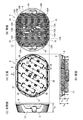
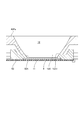
- FIG. 2 is a cross-sectional view taken along the line AA in FIG. 3A and 3B are diagrams showing the configuration of the instrument main body.
- FIG. 3A is a front view
- FIG. 3B is a rear view
- FIG. 3C is a side view
- FIG. 3D is a bottom view. is there.
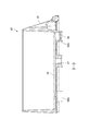
- FIG. 4 is a cross-sectional view taken along line BB in FIG.
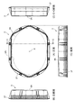
- FIG. 5 is a configuration diagram of the front cover
- FIG. 5 (A) is a front view
- FIG. 5 (B) is a side view
- FIG. 6 is a configuration diagram of the power supply box body
- FIG. 6 (A) is a front view
- FIG. 6 (B) is a top view
- FIG. 6 (C) is a bottom view
- FIG. 6 (D) is a left side view
- FIG. 6E is a rear view
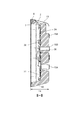
- FIG. 7 is a cross-sectional view taken along the line DD of FIG.
- FIG. 8 is a cross-sectional view of the reflector.
- FIG. 9 is a configuration diagram of the base end side part
- FIG. 9 (A) is a front view
- FIG. 9 (B) is a top view
- FIG. 9 (C) is a bottom view
- FIG. 9 (A) is a front view
- FIG. 9 (B) is a top view
- FIG. 9 (C) is a bottom view
- FIG. 9 (A) is a front view
- FIG. 9 (B) is a top view
- FIG. 9 (C) is a bottom view
- FIG. 10 is a configuration diagram of the tip side part
- FIG. 10 (A) is a front view
- FIG. 10 (B) is a top view
- FIG. 10 (C) is a bottom view
- FIG. 10 (D) is a left side view. is there.
- FIG. 11 is an explanatory diagram of the spacer.
- FIG. 1 is a diagram showing an external configuration of an LED lighting apparatus 1 according to the present embodiment
- FIG. 1 (A) is a front view
- FIG. 1 (B) is a side view
- FIG. 2 is a cross-sectional view taken along line AA in FIG.
- the LED luminaire 1 is a projector mainly used for outdoor light-up lighting, production lighting, sports lighting, stadium lighting, and the like, and is suitably configured for distant lighting that is several tens to hundreds of meters away.
- the LED lighting device 1 includes a device main body 2, a front cover 3, a power supply box 4, a connection box 5, and an arm 6.
- FIGS. 3A and 3B are diagrams showing the configuration of the instrument main body 2.
- FIG. 3A is a front view
- FIG. 3B is a rear view
- FIG. 3C is a left side view
- FIG. 3D is a bottom view.
- FIG. 4 is a cross-sectional view taken along the line BB of FIG.
- the instrument body 2 has a tray shape with an open front, and is manufactured by die casting using an aluminum alloy or the like as a high thermal conductivity material.
- a plurality of LEDs 9 that are light sources and a plurality of reflectors 10 that control the light distribution of the LEDs 9 are housed in the instrument body 2.
- the LED 9 has a chip-on-board (COB) in which a large number of LED elements are densely arranged to form a planar light emitting portion 9A having a substantially circular shape (which may also be a quadrangle) in order to increase the amount of light and increase the brightness.
- COB type LED Structure light emitting device
- the LED 9 is mounted on a ceramic substrate 11 having excellent electrical insulation and thermal conductivity, and is placed on the bottom surface 2A of the instrument body 2. Thereby, while maintaining the electrical insulation of LED9 and the instrument main body 2 with the ceramic substrate 11, the heat_generation
- the LED 9 is not necessarily limited to a COB type LED. Further, the mounting substrate of the LED 9 is not limited to the ceramic substrate 11.
- the reflector 10 has a reflecting surface 12 corresponding to the LED 9 as shown in FIG.
- the reflecting surface 12 is formed as a rotating paraboloid, which is one form of a rotational curved surface.
- a bottom opening 12A1 is formed at the base end portion 12A of the reflecting surface 12, and the LED 9 is disposed at a position facing the bottom opening 12A1.
- the optical axis of the LED 9 and the rotation axis (center axis O (FIG. 8)) of the reflection surface 12 are coaxially arranged, and the light of the LED 9 is collimated from the tip portion 12B and emitted from the reflection surface 12.
- the reflector 10 is made of a resin material and is reduced in weight as compared with a case where a metal material is used as a base material. A high reflectivity is obtained by applying a mirror finish such as metal coating to the reflecting surface 12.
- the LED lighting apparatus 1 includes a plurality of sets of LEDs 9 and reflecting surfaces 12, and the reflecting surfaces 12 are arranged with the central axes O parallel to each other. More specifically, as shown in FIG. 1, the respective reflecting surfaces 12 are arranged closest in the front view. As a result, parallel light having a large light beam cross section (so-called spot diameter) can be obtained as irradiation light without separating the respective outgoing lights from the reflecting surface 12. Further, since a high-brightness LED is used for the LED 9 as a light source, it is possible to illuminate a distant object at a distance of several tens to hundreds of meters with high illuminance. Moreover, in this LED lighting fixture 1, as shown in FIG. 1, the sighting device 14 is provided in the upper part of the instrument main body 2, and it is easy to match
- an engagement piece 31 for positioning the ceramic substrate 11 of the LED 9 is provided on the bottom surface 2 ⁇ / b> A of the instrument body 2, and the reflector 10 is screwed corresponding to the engagement piece 31.
- a screwing portion 32 for fastening and fixing is provided.
- the reflecting surface 12 may be a spheroidal surface instead of the rotating paraboloid, and may be configured to emit light that is condensed at a distance, or may be another rotating curved surface shape such as a rotating hyperbolic surface. Moreover, you may use combining the reflective surface 12 of a different rotational curved surface shape. For example, some of the plurality of reflecting surfaces 12 may be rotating paraboloids, and the others may be rotating ellipsoids to irradiate parallel light and condensed light exclusively or simultaneously.
- FIG. 5A and 5B are configuration diagrams of the front cover 3.
- FIG. 5A is a front view
- FIG. 5B is a left side view
- FIG. 5C is a bottom view
- the front cover 3 is a cover member made of a transparent resin that covers the front surface of the instrument main body 2.
- the front cover 3 has a tray shape having a flat portion 3 ⁇ / b> A having substantially the same size and shape as the front opening 7 of the instrument main body 2.
- the flange 37 is formed in the edge part.
- a flange 8 is integrally provided at the edge of the front opening 7 of the instrument body 2, and a flange 37 of the front cover 3 is fixed to the flange 8 by screwing.
- the opening area of the front opening 7 and the area of the flat portion 3 ⁇ / b> A of the front cover 3 are also proportional to the number of the reflecting surfaces 12. growing.
- the flat surface portion 3A becomes wider, distortion in the surface tends to occur, and distortion in which the central portion in the surface is recessed toward the instrument body 2 may occur. If there is a dent associated with the flat surface portion 3A, a spider web covering the dent portion is likely to be formed, and problems such as frequent maintenance for cleaning arise. Therefore, in the LED lighting device 1, as shown in FIG.
- the flat portion 3A of the front cover 3 is slightly bulged at least in a region including the central portion X to form a bulging portion 3A1. Yes. Since the bulging portion 3A1 suppresses the depression of the flat surface portion 3A, it is difficult to make a spider web.
- the power supply box 4 is a container for housing the power supply circuit 21 (FIG. 2) of the LED 9, and is formed of an aluminum alloy or the like that is a high thermal conductivity material. As shown in FIG. A lid body 23 that closes the front opening is provided, and the connection box 5 is fixed to the lid body 23.
- the connection box 5 is a box containing a terminal block 19 for connecting wiring of an external power source such as a commercial power source.
- the connection box 5 and the lid body 23 are provided with through holes (not shown), and the wiring of the power supply circuit 21 is drawn into the connection box 5 through this through hole and connected to the terminal block 19.
- the power supply circuit 21 is a power conversion circuit that converts the power of the external power supply into DC power necessary for driving the LED 9. In addition to the power supply circuit 21, various electric circuits are housed in the power supply box 4 as necessary.
- FIG. 6A and 6B are configuration diagrams of the power supply box main body 22.
- FIG. 6A is a front view
- FIG. 6B is a top view
- FIG. 6C is a bottom view
- FIG. 6D is a left side view
- FIG. 6E is a rear view.
- FIG. 7 is a cross-sectional view taken along the line DD of FIG.
- the power supply box main body 22 is a rectangular parallelepiped case body having an open front, and a large number of heat radiation fins 20 are formed on the left and right side surfaces to enhance internal heat dissipation.
- the lid body 23 is a substantially rectangular plate-like body that covers the front opening 25 of the power supply box body 22 and is fixed with screws. As described above, the connection box 5 is fixed to the front side thereof.
- a plurality of wiring holes 27 are opened in the bottom surface 26 of the power supply box main body 22, and the wiring of the power supply circuit 21 is drawn out to the instrument main body 2 side through the wiring holes 27.
- screw holes 28 for screwing the power box main body 22 to the back surface of the instrument main body 2 are provided at the four corners of the bottom surface 26, and bosses 29 ⁇ / b> A corresponding to these screw holes 28 are on the front side of the bottom surface 26. Is erected.
- These bosses 29A have a columnar shape with a predetermined height provided with screw holes along the central axis, thereby providing a gap between the back surface of the instrument body 2 and fixing the power box body 22 with screws.
- the Each of the wiring holes 27 is also provided with a cylindrical boss 29B having a predetermined height, and the wiring of the power supply circuit 21 is introduced into the instrument body 2 through the boss 29B.
- the power box main body 22 is attached with a gap between the appliance main body 2 and the heat flow between the power supply box main body 22 and the appliance main body 2 is blocked.
- the power supply circuit 21 is attached to the back surface 23 ⁇ / b> A of the lid body 23, thereby more reliably suppressing the influence of the heat generated by the power supply circuit 21 on the instrument body 2. It is said.
- a difference in height is provided between the bosses 15A and 15B for the wiring holes 27 erected on the back surface of the appliance body 2 and the power supply box body 22 and the bosses 29A and 29B having the screw holes 28.
- the height of the bosses 29A, 29B for the screw holes 28 is slightly lower than the height of 15A, 15B, and a gap is provided on the contact surface of the boss having the screw holes 28 when the bosses for the wiring holes 27 are in contact.
- the arm 6 is a fixing bracket for mounting and fixing the instrument body 2 to the installation surface, and is rotatably attached so as to be sandwiched between the left and right sides of the instrument body 2 as shown in FIGS. 1 and 2. Yes.
- a rotation shaft of the arm 6 is provided with a nut 17, and the tightening of the nut 17 restricts the rotation of the instrument body 2.
- the arm 6 is provided with a lever 18 that is used to rotate the instrument body 2.
- the LED lighting apparatus 1 since the reflector 10 protrudes to the front side of the apparatus main body 2, the center of gravity is biased to the front side if no measures are taken. Therefore, as shown in FIG. 1B, the LED lighting is achieved by forming the thickness Tb of the power supply box 4 to be equal to or greater than the thickness Ta of the appliance body 2 (Tb> Ta in this embodiment). The bias of the center of gravity toward the front side of the instrument 1 is suppressed.
- the power supply box 4 is arranged away from the instrument body 2 and the power supply circuit 21 and the connection box 5 are provided on the lid 23 side of the power supply box 4, so Is suppressed more effectively. That is, in this LED lighting device 1, the weight balance in the front-rear direction (the direction connecting the front and the back) when the device body 2 is rotatably supported by the arm 6 is improved, and the installation stability is improved.
- a COB type LED that is an example of a high-power light emitting element is used for the LED 9.
- the temperature of the LED 9 does not exceed a predetermined operating temperature by directly attaching the ceramic substrate 11 on which the LED 9 is mounted to the instrument body 2 made of a high thermal conductivity material and transmitting the heat generated by the LED 9 to the instrument body 2. It is like that.
- a large number of heat radiation fins 13 are integrally formed on the back surface of the instrument main body 2, so that the heat dissipation of the instrument main body 2 is enhanced.
- Each of the radiating fins 13 is formed in a thin plate shape extending from the upper surface to the bottom surface of the instrument main body 2 and is arranged at regular intervals in the left-right width direction.
- the thickness Ta of the instrument main body 2 described above is a value including the depth Tc of the container of the instrument main body 2 and the height Td of the radiating fins 13 as shown in FIG.
- bosses 15A and 15B are erected integrally on the back surface of the instrument body 2.
- the boss 15A is a member that is screwed to the boss 29A of the power supply box 4, and the boss 15B is a cylindrical member that is connected to the boss 29B and has a through hole 38 through which wiring passes.
- these bosses 15A and 15B are provided in a standing space 16 in which a part of the plurality of radiating fins 13 is cut out.
- connection portions 13A to which any of the radiating fins 13 are connected. Heat accumulation is prevented.
- the radiating fins 13 and the bosses 15 ⁇ / b> A and 15 ⁇ / b> B are integrally formed by die casting of the instrument body 2.
- this LED lighting fixture 1 is equipped with the reflector 10 for controlling light distribution as above-mentioned, and is comprised so that light distribution by this reflector 10 can be changed easily. That is, as shown in FIG. 2, the reflector 10 is configured to be separable into a base end part 40Pa and a front end part 40Pb between the base end 12A on the bottom side of the reflecting surface 12 and the front end 12B. Has been. With this configuration, the base end part 40Pb is removed from the base end side part 40Pa and used, or the base end part 40Pb having a different reflection characteristic and light distribution characteristic is used.
- the orientation pattern of the reflecting surface 12 composed of the combination of the side part 40Pa and the tip side part 40Pb can be arbitrarily changed easily. Also, the light distribution can be changed by the combination of the reflecting surface 12 and the optical characteristics of the front cover 3.
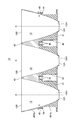
- the reflector 10 is configured such that a medium angle light distribution with a 1/10 beam angle of 62 ° is obtained when only the base end side part 40 Pa in which the reflection surface 12 is mirror-finished is used.
- the reflector 10 is configured so that a medium-wide-angle light distribution with a 1/10 beam angle of 63 ° can be obtained by using a stamped cover with a light diffusion effect as the front cover 3 in combination.
- the reflector 10 has a wide-angle distribution in which the 1/10 beam angle is 87 ° in this configuration 2 by applying a white coating (that is, a light diffusing treatment) instead of the mirror surface treatment to the treatment of the reflection surface of the base part 40Pa.
- the reflector 10 has a narrow-angle light distribution with a 1/10 beam angle of 38 ° by attaching the distal end side part 40Pb having a mirror-finished reflective surface 12 to the proximal end side part 40Pa.
- Configuration 4 similarly to the configuration 2, by using together with the front cover 3 a stamping cover having a light diffusion effect, a narrow medium angle light distribution with a 1/10 beam angle of 40 ° is obtained. (Configuration 5).
- the proximal end side part 40Pa is disposed at a position recessed from the front opening 7. There is a possibility that a lot of light is shielded and the efficiency of the instrument is lowered.
- the depth Tc of the apparatus main body 2 is set to the base end side part 40Pa.
- the height is set to be shallower than the height Te.
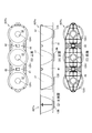
- FIG. 8 is a cross-sectional view of the reflector 10.
- 9 is a configuration diagram of the base end side part 40Pa
- FIG. 9 (A) is a front view
- FIG. 9 (B) is a top view
- FIG. 9 (C) is a bottom view
- FIG. 9 (D) is a left side view.
- FIG. 10 is a configuration diagram of the tip side part 40Pb
- FIG. 10 (A) is a front view
- FIG. 10 (B) is a top view
- FIG. 10 (C) is a bottom view
- FIG. 10 (D) is a left side view. is there.
- FIG. 10 is a configuration diagram of the tip side part 40Pb
- the reflector 10 integrally includes a plurality of reflecting surfaces 12, and the reflecting surfaces 12 are arranged side by side in parallel with the central axis O.
- the reflector 10 includes a proximal side part 40Pa and a distal side part 40Pb so as to separate the reflecting surfaces 12 on the proximal side and the distal side.
- an insertion fixing structure is used for fixing both.
- the base end part 40Pa has a connecting portion 41 that connects adjacent ones of the plurality of reflecting surfaces 12.
- an insertion hole portion 42 is formed in the connecting portion 41 in the contact surface of the tip side part 40Pb.
- the front end side part 40Pb similarly to the base end part 40Pa, has a connecting portion 43 that connects the reflecting surfaces 12 to each other as shown in FIGS. 8 and 10A.
- a claw portion 44 is provided corresponding to the insertion hole 42 in the contact surface of the end part 40Pa.
- the claw portion 44 and the insertion hole portion 42 constitute a coupling portion that couples the proximal end side part 40Pa and the distal end side portion 40Pb, and the claw portion 44 is inserted into the insertion hole portion 42 and locked, so that the proximal side
- the tip side part 40Pb is coupled to the part 40Pa.
- hook claws 46 that are hooked on the convex portions 45 on both ends of the base end side part 40Pa are provided on both ends of the tip end part 40Pb, and the coupling between both is made stronger. ing.
- the plurality of reflectors 10 are arranged in the fixture body 2 so that the reflecting surfaces 12 are in contact with each other, that is, the plurality of reflecting surfaces 12 are arranged in a close-packed manner in a front view.
- each reflector 10 is integrally provided with a screw-fastening piece 47 at the base end portion 12 ⁇ / b> A of the base-side part 40 ⁇ / b> Pa.
- the stopper 32 is fixed with screws. After fixing to the instrument body 2, the bottom opening 12A1 of each reflecting surface 12 is arranged immediately above the LED 9, but if there is a gap between the LED 9 and the bottom opening 12A1, the light of the LED 9 leaks from this gap. Incurs efficiency loss.
- a spacer 50 is provided that is sandwiched between the base end portion 12A of the base end side part 40Pa and the ceramic substrate 11 and fills the gap between the LED 9 and the bottom opening 12A1.
- the spacer 50 is provided with a surface 50A continuous to the reflecting surface 12 of the base end side part 40Pa.
- the surface 50A is reflective, and the shape of the surface 50A is such that the reflecting surface 12 is on the LED 9 side. This coincides with the surface that is formed when extended to the ceramic substrate 11 side.
- the light distribution is also controlled by the surface 50A in the same manner as the reflecting surface 12, and the efficiency is improved and the uneven illumination is prevented.
- the spacer 50 is formed of a resin material as an example of an elastic material, and is pressed against the ceramic substrate 11 by the base end portion 12A as the reflector 10 is screwed to the instrument body 2. Thereby, the adhesiveness of the ceramic substrate 11 and the bottom face 2A of the instrument body 2 is enhanced, and the heat dissipation is enhanced.
- the distal end side part 40Pb can be removed and used, or the distal end side part 40Pb can be used. Can be changed arbitrarily and easily by changing the pattern to one having different reflection characteristics and light distribution characteristics. Furthermore, since at least the distal end of the base end part 40Pa protrudes from the instrument body 2, even when the distal end part 40Pb is detached from the reflector 10 and used, the emitted light of the reflector 10 is transmitted to the instrument body 2. It is not shielded and instrument efficiency is not reduced. Moreover, since the depth Tc in which the instrument main body 2 accommodates the reflector 10 can be made shallow, the weight reduction of the instrument main body 2 is also achieved.
- bond part is cancelled
- the coupling portion is coupled by insertion, it can be easily removed by inserting / removing the distal end side part 40Pb with respect to the proximal end side part 40Pa.
- the coupling portion 41 that couples the reflective surfaces 12 to each other, it is possible to insert and remove the tip side part 40Pb at a time with respect to the plurality of reflective surfaces 12.
- the spacer 50 is provided between the base end side part 40Pa of the reflector 10 and the ceramic substrate 11, light leaking from the gap between the base end side part 40Pa and the ceramic substrate 11 can be prevented. Further, when the reflector 10 presses the ceramic substrate 11 through the spacer 50, the adhesion between the ceramic substrate 11 and the instrument body 2 is enhanced.
- the spacer 50 is provided with a surface 50A continuous to the reflecting surface 12 of the base end side part 40Pa, and the shape of the surface 50A is made to coincide with the shape when the reflecting surface 12 is extended to the ceramic substrate 11 side. Yes. Thereby, the light distribution is controlled by the surface 50A in the same manner as the reflecting surface 12, and the efficiency is improved and the uneven illumination is prevented.
- the reflector 10 is configured to integrally include a plurality of reflecting surfaces 12 arranged so that the rotation axes (center axes O) are parallel to each other. Thereby, the light distribution can be changed by attaching and detaching the tip side parts 40Pb of the plurality of reflecting surfaces 12 all at once.
- the bosses 15A and 15B are erected. According to this configuration, since the power supply box 4 is supported by the bosses 15 ⁇ / b> A and 15 ⁇ / b> B, the heat radiation fins 13 can be provided also on the portion of the back surface of the instrument body 2 that is covered with the power supply box 4. In particular, since at least one radiating fin 13 is connected to the bosses 15A and 15B, heat accumulation in the bosses 15A and 15B is prevented.
- the LED is illustrated as an example of the light-emitting element, but other light-emitting elements such as an organic EL can also be used.
- the light source is not limited to the light emitting element.
- separate the reflective surface 12 into two of the base end side part 40Pa and the front end side part 40Pb was illustrated as the reflector 10.
- the tip side part 40Pb may be further separable into two or more.
- the LED lighting device 1 when the LED lighting device 1 is installed at an angle, the light distribution due to the tilt of the optical axis is likely to occur due to vibration or the weight of the reflector 10, so that the front surface of the device main body 2 is placed in order to obtain a more stable light distribution.
- the inner surface of the front cover 3 to be covered is brought into contact with the tip of the reflector 10 (the tip of the tip side part 40Pb in this embodiment), and the reflector 10 is pressed by the front cover 3 to prevent the optical axis from being tilted. good.
- the LED lighting apparatus 1 described in the above-described embodiment can illuminate an irradiation field separated by several tens of meters to hundreds of tens of meters with sufficient brightness, and thus is suitably used as a projector that produces a high-rise building. Can do. Moreover, it can use suitably also for the stadium lighting which needs to illuminate the wide range from a distant place, such as a baseball field and a stadium, by arranging the LED lighting fixture 1 side by side.
Abstract
Description
本発明は、上述した事情に鑑みてなされたものであり、配光を簡単に変更できる照明器具を提供することを目的とする。
さらに、少なくとも基端側のパーツの先端が器具本体より突出することから、反射体から先端側を取り外して使用した場合であっても、反射体の出射光が器具本体に遮蔽されることがなく器具効率が低下することがない。また、器具本体が反射体を納める深さを浅くできるから、器具本体の軽量化も図られる。
図1は本実施形態に係るLED照明器具1の外観構成を示す図であり、図1(A)は正面図、図1(B)は側面図である。また図2は図1(A)のA-A線断面図である。
LED照明器具1は、主に屋外のライトアップ照明や演出照明、スポーツ照明、スタジアム照明等に用いられる投光器であり、数十メートル~百数十メートル離れた遠方の照明に好適に構成されている。具体的には、図1、及び図2に示すように、LED照明器具1は、器具本体2と、前面カバー3と、電源ボックス4と、結線ボックス5と、アーム6とを備えている。
器具本体2は、図3、及び図4に示すように、正面が開口したトレー状を成し、高熱伝導性材であるアルミニウム合金等を材料に用いたダイカスト成型によって造られている。器具本体2には、図2に示すように、光源たる複数のLED9と、LED9の配光を制御する複数の反射体10とが納められている。
前面カバー3は、器具本体2の正面を覆う透明樹脂製のカバー部材であり、図5に示すように、器具本体2の正面開口7と略同じ寸法形状の平面部3Aを有したトレー状を成し、縁部にはフランジ37が形成されている。図3に示すように、器具本体2の正面開口7の縁部にもフランジ8が一体に設けられており、このフランジ8に前面カバー3のフランジ37をネジ止めして固定される。
そこで、このLED照明器具1では、図5(A)に示すように、前面カバー3の平面部3Aに、少なくとも中央部Xを含む領域を僅かに膨出させて膨出部3A1が形成されている。この膨出部3A1により平面部3Aの凹みが抑えられることから蜘蛛の巣が作られにくくなる。
電源ボックス本体22は、正面が開口した直方体形状のケース体であり、左右の側面には、多数の放熱フィン20が形成されて内部の放熱性が高められている。蓋体23は、電源ボックス本体22の正面開口25を覆ってネジ止め固定される略矩形板状体であり、上述の通り、その表側に結線ボックス5が固定される。
このように電源ボックス本体22が器具本体2との間に隙間を設けて取り付けられることで、電源ボックス本体22と器具本体2の間の熱の流通が遮断される。これに加え、この電源ボックス4では、図2に示すように、電源回路21を蓋体23の裏面23Aに取付けており、電源回路21の発熱が器具本体2に及ぼす影響をより確実に抑えることとしている。
更に、ボス15A、15Bとボス29A、29Bの間にリング状のパッキン(本実施例ではOリング(図示せず))を介在させているため、ボス29A、29Bのネジ孔28にボルトを装着して固定したときに、器具本体2と電源ボックス本体22との間の配線孔27の防水性が高められる構成となっている。
すなわち、このLED照明器具1では、器具本体2をアーム6で回動自在に支持したときの前後方向(正面と背面を結ぶ方向)の重量バランスが良好となり設置の安定性が向上する。
更に、この器具本体2の背面に、図3に示すように、多数の放熱フィン13が一体に形成されており、器具本体2の放熱性が高められている。それぞれの放熱フィン13は、器具本体2の上面から底面まで延びた薄板状に形成されており、左右の幅方向に一定間隔で配列されている。なお、上述した器具本体2の厚さTaは、図3(D)に示すように、器具本体2の容器の深さTcと放熱フィン13の高さTdを含む値である。
すなわち、この反射体10は、図2に示すように、反射面12の底部側である基端部12Aから先端部12Bの間で基端側パーツ40Pa、及び先端側パーツ40Pbに分離可能に構成されている。この構成により、基端側パーツ40Paから先端側パーツ40Pbを取り外して使用したり、或いは、異なった反射特性や配光特性を有する先端側パーツ40Pbに変えて使用したりすることで、これら基端側パーツ40Pa、及び先端側パーツ40Pbの組み合わせから成る反射面12の配向パターンを任意に簡単に変更可能となっている。また、反射面12と前面カバー3の光学特性との組み合わせによっても、配光が変更可能に成されている。
これにより、反射体10から先端側パーツ40Pbを取り外して使用した場合であっても、基端側パーツ40Paの先端が器具本体2より突出することから、器具本体2に遮蔽されることなく反射体10から出射させることができ、器具効率の低下が防止される。また、器具本体2の深さTcが浅くなることで軽量化も図られる。
反射体10は、図8に示すように、複数の反射面12を一体に有し、各反射面12が中心軸Oを平行に横並びに配置されている。そして反射体10は、各反射面12を基端側、及び先端側で分離するように、基端側パーツ40Pa、及び先端側パーツ40Pbを備えている。この反射体10では、基端側パーツ40Paと先端側パーツ40Pbの着脱を容易とするために、両者の固定には差し込み固定構造が用いられている。
爪部44、及び挿入穴部42による差し込み結合構造により、基端側パーツ40Paに対し先端側パーツ40Pbを簡単に抜き差しして取り外しや交換等が容易になる。
それぞれの反射体10は、基端側パーツ40Paの基端部12Aに、図9に示すように、ネジ止め片47が一体に設けられており、このネジ止め片47を、器具本体2のネジ止め部32にネジ止めして固定される。器具本体2への固定後には、LED9の直上に各反射面12の底部開口12A1が配置されるが、LED9と底部開口12A1の間に隙間が存在すると、この隙間からLED9の光が漏れてしまい効率低下を招く。
さらに、少なくとも基端側パーツ40Paの先端が器具本体2より突出することから、反射体10から先端側パーツ40Pbを取り外して使用した場合であっても、反射体10の出射光が器具本体2に遮蔽されることがなく器具効率が低下することがない。また、器具本体2が反射体10を納める深さTcを浅くできるから、器具本体2の軽量化も図られる。
また、反射面12同士を連結する連結部41に結合部を設けることで、複数の反射面12に対して一度に先端側パーツ40Pbの抜き差しが可能になる。
これにより、面50Aによっても反射面12と同様に配光が制御され、効率の向上とともに照度ムラの防止が図られる。
この構成によれば、ボス15A、15Bで電源ボックス4を支持するため、器具本体2の背面のうち、当該電源ボックス4で覆われる箇所にも放熱フィン13を設けることがでる。
特に、少なくとも1つの放熱フィン13をボス15A、15Bに接続する構成としたため、ボス15A、15Bへの熱溜まりが防止される。
上述した実施形態では、発光素子の一例としてLEDを例示したが、例えば有機EL等の他の発光素子を用いることもできる。また光源は、発光素子に限定されるものではない。
また、反射体10として、反射面12を基端側パーツ40Paと先端側パーツ40Pbとの2つに分離可能な構成を例示した。しかしながら、先端側パーツ40Pbを2つ以上に更に分離可能に構成しても良い。
また、LED照明器具1を傾けて設置する場合、振動や反射体10の自重により光軸の傾きによる配光のズレが生じ易いため、より安定した配光を得るために器具本体2の正面を覆う前面カバー3の内面を、反射体10の先端(本実施例では先端側パーツ40Pbの先端)へ当接させ、前面カバー3で反射体10を押さえて光軸の傾きを防止する構成としても良い。
2 器具本体
3 前面カバー
3A 平面部
4 電源ボックス
9 LED(光源、発光素子)
10 反射体
11 セラミック基板(実装基板)
12 反射面
12A 基端部
12B 先端部
12A1 底部開口
13 放熱フィン
13A 接続部
15A、15B、29A、29B ボス
16 立設スペース
3A1 膨出部
40Pa 基端側パーツ
40Pb 先端側パーツ
42 挿入穴部(結合部)
44 爪部(結合部)
50 スペーサ
50A 面
O 中心軸(回転軸)
Claims (9)
- 光源と、回転曲面形状の反射面を有する反射体とを器具本体に収めた照明器具において、
前記反射体を前記反射面の基端側と先端側とに分離可能にし、基端側のパーツの先端を前記器具本体より突出させたことを特徴とする照明器具。 - 前記反射体の基端側のパーツと前記先端側のパーツを結合する結合部を備えることを特徴とする請求項1に記載の照明器具。
- 前記反射体は、連結部で連結された複数の反射面を有し、
前記基端側のパーツと前記先端側のパーツを差し込み結合する前記結合部を、前記連結部に備えることを特徴とする請求項2に記載の照明器具。 - 複数の前記反射体を備え、前記反射体の各々を前記器具本体の内部に配列したことを特徴とする請求項3に記載の照明器具。
- 前記光源は、発光素子と、当該発光素子を実装した発光素子基板と、を備え、
前記反射体の基端側のパーツと、前記発光素子基板との間にスペーサを設けたことを特徴とする請求項1~4のいずれかに記載の照明器具。 - 前記スペーサには、前記反射体の基端側のパーツの反射面に連続する面を有し、当該面の形状を、前記反射面を前記発光素子基板の側に延長したときの形状と一致させたことを特徴とする請求項5に記載の照明器具。
- 前記反射体は、回転軸が互いに平行になるように配置された複数の前記反射面を一体に備えることを特徴とする請求項1~6のいずれかに記載の照明器具。
- 前記光源に電力を供給する電気回路を納めた電源ボックスを備え、
前記器具本体の背面には、一方向に延びる複数の放熱フィンを有し、
前記放熱フィンの一部が除かれてできたスペースに、前記放熱フィンとの間に隙間をあけて前記電源ボックスを支持するボスを立設したことを特徴とする請求項1~7のいずれかに記載の照明器具。 - 少なくとも1つの前記放熱フィンを前記ボスに接続したことを特徴とする請求項8に記載の照明器具。
Priority Applications (4)
| Application Number | Priority Date | Filing Date | Title |
|---|---|---|---|
| CN201380076922.4A CN105247271B (zh) | 2013-05-31 | 2013-08-22 | 照明器具 |
| US14/890,274 US20160084475A1 (en) | 2013-05-31 | 2013-08-22 | Lighting apparatus |
| JP2015519601A JP6004101B2 (ja) | 2013-08-22 | 2013-08-22 | 照明器具 |
| HK16104064.5A HK1216113A1 (zh) | 2013-05-31 | 2016-04-08 | 照明器具 |
Applications Claiming Priority (2)
| Application Number | Priority Date | Filing Date | Title |
|---|---|---|---|
| JP2013-115351 | 2013-05-31 | ||
| JP2013115351A JP5753221B2 (ja) | 2013-05-31 | 2013-05-31 | 照明器具 |
Publications (1)
| Publication Number | Publication Date |
|---|---|
| WO2014192169A1 true WO2014192169A1 (ja) | 2014-12-04 |
Family
ID=51988234
Family Applications (1)
| Application Number | Title | Priority Date | Filing Date |
|---|---|---|---|
| PCT/JP2013/072432 WO2014192169A1 (ja) | 2013-05-31 | 2013-08-22 | 照明器具 |
Country Status (5)
| Country | Link |
|---|---|
| US (1) | US20160084475A1 (ja) |
| JP (1) | JP5753221B2 (ja) |
| CN (1) | CN105247271B (ja) |
| HK (1) | HK1216113A1 (ja) |
| WO (1) | WO2014192169A1 (ja) |
Cited By (5)
| Publication number | Priority date | Publication date | Assignee | Title |
|---|---|---|---|---|
| JP2017033680A (ja) * | 2015-07-29 | 2017-02-09 | パナソニックIpマネジメント株式会社 | 照明器具 |
| JP2017147290A (ja) * | 2016-02-16 | 2017-08-24 | 岩崎電気株式会社 | Ledユニット、及び照明装置 |
| JP2018081893A (ja) * | 2016-11-18 | 2018-05-24 | アイリスオーヤマ株式会社 | 照明装置 |
| JP2019515422A (ja) * | 2016-04-25 | 2019-06-06 | シャット−アール−シールド インコーポレイテッド | Led照明器具 |
| KR102273709B1 (ko) * | 2020-11-25 | 2021-07-06 | (주) 매그나텍 | 배광각 제어를 통한 집중적이고 균일한 광 조사가 가능한 고출력 비대칭 led 조명장치 |
Families Citing this family (8)
| Publication number | Priority date | Publication date | Assignee | Title |
|---|---|---|---|---|
| FR3032516B1 (fr) * | 2015-02-06 | 2021-04-16 | Valeo Vision | Dispositif reflecteur d'un module lumineux avec blindage electromagnetique |
| JP6435995B2 (ja) * | 2015-06-04 | 2018-12-12 | 岩崎電気株式会社 | 高天井照明器具 |
| CN105757530A (zh) * | 2016-02-03 | 2016-07-13 | 南通中铁华宇电气有限公司 | 基于高散热基板及一体封装技术的高功率投光led光引擎 |
| CA3020725C (en) * | 2016-04-13 | 2021-03-16 | Thomas & Betts International Llc | Reflector and led assembly for emergency lighting head |
| USD790758S1 (en) * | 2016-05-11 | 2017-06-27 | SpeedTech Lights, Inc. | LED optical lens |
| JP6685195B2 (ja) * | 2016-07-20 | 2020-04-22 | 日立グローバルライフソリューションズ株式会社 | 照明装置 |
| WO2019162209A1 (en) * | 2018-02-20 | 2019-08-29 | Signify Holding B.V. | A stadium lighting system and luminaire |
| KR200491584Y1 (ko) * | 2018-11-14 | 2020-05-04 | 김경철 | 스팟조명용 전구소켓 |
Citations (6)
| Publication number | Priority date | Publication date | Assignee | Title |
|---|---|---|---|---|
| JPH01253101A (ja) * | 1988-03-31 | 1989-10-09 | Toshiba Lighting & Technol Corp | 投光器 |
| JPH08124402A (ja) * | 1994-10-25 | 1996-05-17 | Matsushita Electric Works Ltd | 投光照明器具 |
| JP2008098028A (ja) * | 2006-10-13 | 2008-04-24 | Ichikoh Ind Ltd | 車両用前照灯 |
| JP2009087644A (ja) * | 2007-09-28 | 2009-04-23 | Toshiba Lighting & Technology Corp | 照明装置 |
| JP2012009280A (ja) * | 2010-06-24 | 2012-01-12 | Eye Lighting Syst Corp | Led照明器具 |
| JP2013089580A (ja) * | 2011-10-24 | 2013-05-13 | Eye Lighting Syst Corp | 光源ユニット |
Family Cites Families (14)
| Publication number | Priority date | Publication date | Assignee | Title |
|---|---|---|---|---|
| CN101709857B (zh) * | 2008-09-16 | 2012-01-25 | 东芝照明技术株式会社 | 光源单元以及使用此光源单元的照明器具 |
| CN101749663A (zh) * | 2008-12-05 | 2010-06-23 | 东芝照明技术株式会社 | 照明器具 |
| CN104019386B (zh) * | 2009-02-19 | 2016-05-11 | 东芝照明技术株式会社 | 灯装置以及照明器具 |
| CN101761799B (zh) * | 2009-06-05 | 2011-06-29 | 海洋王照明科技股份有限公司 | 一种led灯具 |
| DE202010002676U1 (de) * | 2010-02-23 | 2011-07-26 | Zumtobel Lighting Gmbh | Einbauleuchte mit Basiskörper und domförmigem Reflektor |
| JP2011175868A (ja) * | 2010-02-24 | 2011-09-08 | Toshiba Lighting & Technology Corp | 照明装置 |
| CN101761811A (zh) * | 2010-02-28 | 2010-06-30 | 东莞市万丰纳米材料有限公司 | Led泛光照明装置及增加其照度的方法 |
| JP2012129003A (ja) * | 2010-12-14 | 2012-07-05 | Kyocera Corp | 照明装置 |
| CN202118810U (zh) * | 2011-05-30 | 2012-01-18 | 侯立新 | Led反光杯 |
| JP2014011045A (ja) * | 2012-06-29 | 2014-01-20 | Toshiba Lighting & Technology Corp | 照明装置及び照明システム |
| US8430536B1 (en) * | 2012-10-01 | 2013-04-30 | Zumtobel Lighting Inc. | LED lighting system including TIR optic |
| JP2014086159A (ja) * | 2012-10-19 | 2014-05-12 | Toshiba Lighting & Technology Corp | 照明器具 |
| CN202947079U (zh) * | 2012-11-30 | 2013-05-22 | 昆山安磊照明科技有限公司 | 一种灯具反射罩 |
| JP6179760B2 (ja) * | 2013-04-01 | 2017-08-16 | 東芝ライテック株式会社 | 照明器具 |
-
2013
- 2013-05-31 JP JP2013115351A patent/JP5753221B2/ja active Active
- 2013-08-22 CN CN201380076922.4A patent/CN105247271B/zh active Active
- 2013-08-22 US US14/890,274 patent/US20160084475A1/en not_active Abandoned
- 2013-08-22 WO PCT/JP2013/072432 patent/WO2014192169A1/ja active Application Filing
-
2016
- 2016-04-08 HK HK16104064.5A patent/HK1216113A1/zh unknown
Patent Citations (6)
| Publication number | Priority date | Publication date | Assignee | Title |
|---|---|---|---|---|
| JPH01253101A (ja) * | 1988-03-31 | 1989-10-09 | Toshiba Lighting & Technol Corp | 投光器 |
| JPH08124402A (ja) * | 1994-10-25 | 1996-05-17 | Matsushita Electric Works Ltd | 投光照明器具 |
| JP2008098028A (ja) * | 2006-10-13 | 2008-04-24 | Ichikoh Ind Ltd | 車両用前照灯 |
| JP2009087644A (ja) * | 2007-09-28 | 2009-04-23 | Toshiba Lighting & Technology Corp | 照明装置 |
| JP2012009280A (ja) * | 2010-06-24 | 2012-01-12 | Eye Lighting Syst Corp | Led照明器具 |
| JP2013089580A (ja) * | 2011-10-24 | 2013-05-13 | Eye Lighting Syst Corp | 光源ユニット |
Cited By (5)
| Publication number | Priority date | Publication date | Assignee | Title |
|---|---|---|---|---|
| JP2017033680A (ja) * | 2015-07-29 | 2017-02-09 | パナソニックIpマネジメント株式会社 | 照明器具 |
| JP2017147290A (ja) * | 2016-02-16 | 2017-08-24 | 岩崎電気株式会社 | Ledユニット、及び照明装置 |
| JP2019515422A (ja) * | 2016-04-25 | 2019-06-06 | シャット−アール−シールド インコーポレイテッド | Led照明器具 |
| JP2018081893A (ja) * | 2016-11-18 | 2018-05-24 | アイリスオーヤマ株式会社 | 照明装置 |
| KR102273709B1 (ko) * | 2020-11-25 | 2021-07-06 | (주) 매그나텍 | 배광각 제어를 통한 집중적이고 균일한 광 조사가 가능한 고출력 비대칭 led 조명장치 |
Also Published As
| Publication number | Publication date |
|---|---|
| CN105247271A (zh) | 2016-01-13 |
| JP5753221B2 (ja) | 2015-07-22 |
| JP2014235821A (ja) | 2014-12-15 |
| CN105247271B (zh) | 2017-08-25 |
| HK1216113A1 (zh) | 2016-10-14 |
| US20160084475A1 (en) | 2016-03-24 |
Similar Documents
| Publication | Publication Date | Title |
|---|---|---|
| WO2014192169A1 (ja) | 照明器具 | |
| JP5486001B2 (ja) | 熱消散システムを備える照明器具 | |
| JP5182634B2 (ja) | 照明器具 | |
| US20100128491A1 (en) | Recessed luminaire | |
| JP2010034546A (ja) | 発光素子ランプ及び照明器具 | |
| JP2009129809A (ja) | 照明装置 | |
| JP5919505B2 (ja) | 照明器具 | |
| JP2011175868A (ja) | 照明装置 | |
| JP6311861B2 (ja) | 照明器具 | |
| JP5958805B2 (ja) | 光源装置及び照明装置 | |
| JP2015228303A (ja) | 光源ユニット及び照明器具 | |
| JP5685722B2 (ja) | 照明器具 | |
| JP6004101B2 (ja) | 照明器具 | |
| JP2011175869A (ja) | 光源ユニット及び照明装置 | |
| JP5948293B2 (ja) | 照明装置 | |
| JP2015212997A (ja) | 照明装置 | |
| WO2013046333A1 (ja) | 照明器具 | |
| JP2014089939A (ja) | Led照明器具 | |
| JP5888624B2 (ja) | 照明器具 | |
| JP6723099B2 (ja) | 照明器具 | |
| JP6886395B2 (ja) | 照明器具 | |
| JP7182155B2 (ja) | 光源ユニット及び照明器具 | |
| JP6931833B2 (ja) | 照明器具 | |
| JP2021007114A (ja) | 照明器具 | |
| JP5897744B2 (ja) | 照明器具及びled光源ユニット |
Legal Events
| Date | Code | Title | Description |
|---|---|---|---|
| 121 | Ep: the epo has been informed by wipo that ep was designated in this application |
Ref document number: 13885876 Country of ref document: EP Kind code of ref document: A1 |
|
| ENP | Entry into the national phase |
Ref document number: 2015519601 Country of ref document: JP Kind code of ref document: A |
|
| WWE | Wipo information: entry into national phase |
Ref document number: 14890274 Country of ref document: US |
|
| NENP | Non-entry into the national phase |
Ref country code: DE |
|
| 122 | Ep: pct application non-entry in european phase |
Ref document number: 13885876 Country of ref document: EP Kind code of ref document: A1 |