WO2014189090A1 - アルミニウム合金板、接合体及び自動車用部材 - Google Patents
アルミニウム合金板、接合体及び自動車用部材 Download PDFInfo
- Publication number
- WO2014189090A1 WO2014189090A1 PCT/JP2014/063512 JP2014063512W WO2014189090A1 WO 2014189090 A1 WO2014189090 A1 WO 2014189090A1 JP 2014063512 W JP2014063512 W JP 2014063512W WO 2014189090 A1 WO2014189090 A1 WO 2014189090A1
- Authority
- WO
- WIPO (PCT)
- Prior art keywords
- film
- aluminum alloy
- adhesive
- alloy plate
- amount
- Prior art date
- Legal status (The legal status is an assumption and is not a legal conclusion. Google has not performed a legal analysis and makes no representation as to the accuracy of the status listed.)
- Ceased
Links
Images





Classifications
-
- B—PERFORMING OPERATIONS; TRANSPORTING
- B32—LAYERED PRODUCTS
- B32B—LAYERED PRODUCTS, i.e. PRODUCTS BUILT-UP OF STRATA OF FLAT OR NON-FLAT, e.g. CELLULAR OR HONEYCOMB, FORM
- B32B15/00—Layered products comprising a layer of metal
- B32B15/04—Layered products comprising a layer of metal comprising metal as the main or only constituent of a layer, which is next to another layer of the same or of a different material
- B32B15/08—Layered products comprising a layer of metal comprising metal as the main or only constituent of a layer, which is next to another layer of the same or of a different material of synthetic resin
-
- B—PERFORMING OPERATIONS; TRANSPORTING
- B32—LAYERED PRODUCTS
- B32B—LAYERED PRODUCTS, i.e. PRODUCTS BUILT-UP OF STRATA OF FLAT OR NON-FLAT, e.g. CELLULAR OR HONEYCOMB, FORM
- B32B15/00—Layered products comprising a layer of metal
- B32B15/04—Layered products comprising a layer of metal comprising metal as the main or only constituent of a layer, which is next to another layer of the same or of a different material
- B32B15/043—Layered products comprising a layer of metal comprising metal as the main or only constituent of a layer, which is next to another layer of the same or of a different material of metal
-
- B—PERFORMING OPERATIONS; TRANSPORTING
- B32—LAYERED PRODUCTS
- B32B—LAYERED PRODUCTS, i.e. PRODUCTS BUILT-UP OF STRATA OF FLAT OR NON-FLAT, e.g. CELLULAR OR HONEYCOMB, FORM
- B32B15/00—Layered products comprising a layer of metal
- B32B15/20—Layered products comprising a layer of metal comprising aluminium or copper
-
- B—PERFORMING OPERATIONS; TRANSPORTING
- B32—LAYERED PRODUCTS
- B32B—LAYERED PRODUCTS, i.e. PRODUCTS BUILT-UP OF STRATA OF FLAT OR NON-FLAT, e.g. CELLULAR OR HONEYCOMB, FORM
- B32B27/00—Layered products comprising a layer of synthetic resin
- B32B27/18—Layered products comprising a layer of synthetic resin characterised by the use of special additives
-
- B—PERFORMING OPERATIONS; TRANSPORTING
- B32—LAYERED PRODUCTS
- B32B—LAYERED PRODUCTS, i.e. PRODUCTS BUILT-UP OF STRATA OF FLAT OR NON-FLAT, e.g. CELLULAR OR HONEYCOMB, FORM
- B32B27/00—Layered products comprising a layer of synthetic resin
- B32B27/30—Layered products comprising a layer of synthetic resin comprising vinyl (co)polymers; comprising acrylic (co)polymers
- B32B27/302—Layered products comprising a layer of synthetic resin comprising vinyl (co)polymers; comprising acrylic (co)polymers comprising aromatic vinyl (co)polymers, e.g. styrenic (co)polymers
-
- B—PERFORMING OPERATIONS; TRANSPORTING
- B32—LAYERED PRODUCTS
- B32B—LAYERED PRODUCTS, i.e. PRODUCTS BUILT-UP OF STRATA OF FLAT OR NON-FLAT, e.g. CELLULAR OR HONEYCOMB, FORM
- B32B27/00—Layered products comprising a layer of synthetic resin
- B32B27/30—Layered products comprising a layer of synthetic resin comprising vinyl (co)polymers; comprising acrylic (co)polymers
- B32B27/304—Layered products comprising a layer of synthetic resin comprising vinyl (co)polymers; comprising acrylic (co)polymers comprising vinyl halide (co)polymers, e.g. PVC, PVDC, PVF, PVDF
-
- B—PERFORMING OPERATIONS; TRANSPORTING
- B32—LAYERED PRODUCTS
- B32B—LAYERED PRODUCTS, i.e. PRODUCTS BUILT-UP OF STRATA OF FLAT OR NON-FLAT, e.g. CELLULAR OR HONEYCOMB, FORM
- B32B27/00—Layered products comprising a layer of synthetic resin
- B32B27/30—Layered products comprising a layer of synthetic resin comprising vinyl (co)polymers; comprising acrylic (co)polymers
- B32B27/308—Layered products comprising a layer of synthetic resin comprising vinyl (co)polymers; comprising acrylic (co)polymers comprising acrylic (co)polymers
-
- B—PERFORMING OPERATIONS; TRANSPORTING
- B32—LAYERED PRODUCTS
- B32B—LAYERED PRODUCTS, i.e. PRODUCTS BUILT-UP OF STRATA OF FLAT OR NON-FLAT, e.g. CELLULAR OR HONEYCOMB, FORM
- B32B27/00—Layered products comprising a layer of synthetic resin
- B32B27/32—Layered products comprising a layer of synthetic resin comprising polyolefins
-
- B—PERFORMING OPERATIONS; TRANSPORTING
- B32—LAYERED PRODUCTS
- B32B—LAYERED PRODUCTS, i.e. PRODUCTS BUILT-UP OF STRATA OF FLAT OR NON-FLAT, e.g. CELLULAR OR HONEYCOMB, FORM
- B32B27/00—Layered products comprising a layer of synthetic resin
- B32B27/34—Layered products comprising a layer of synthetic resin comprising polyamides
-
- B—PERFORMING OPERATIONS; TRANSPORTING
- B32—LAYERED PRODUCTS
- B32B—LAYERED PRODUCTS, i.e. PRODUCTS BUILT-UP OF STRATA OF FLAT OR NON-FLAT, e.g. CELLULAR OR HONEYCOMB, FORM
- B32B27/00—Layered products comprising a layer of synthetic resin
- B32B27/36—Layered products comprising a layer of synthetic resin comprising polyesters
-
- B—PERFORMING OPERATIONS; TRANSPORTING
- B32—LAYERED PRODUCTS
- B32B—LAYERED PRODUCTS, i.e. PRODUCTS BUILT-UP OF STRATA OF FLAT OR NON-FLAT, e.g. CELLULAR OR HONEYCOMB, FORM
- B32B27/00—Layered products comprising a layer of synthetic resin
- B32B27/40—Layered products comprising a layer of synthetic resin comprising polyurethanes
-
- B—PERFORMING OPERATIONS; TRANSPORTING
- B32—LAYERED PRODUCTS
- B32B—LAYERED PRODUCTS, i.e. PRODUCTS BUILT-UP OF STRATA OF FLAT OR NON-FLAT, e.g. CELLULAR OR HONEYCOMB, FORM
- B32B7/00—Layered products characterised by the relation between layers; Layered products characterised by the relative orientation of features between layers, or by the relative values of a measurable parameter between layers, i.e. products comprising layers having different physical, chemical or physicochemical properties; Layered products characterised by the interconnection of layers
- B32B7/04—Interconnection of layers
- B32B7/12—Interconnection of layers using interposed adhesives or interposed materials with bonding properties
-
- C—CHEMISTRY; METALLURGY
- C09—DYES; PAINTS; POLISHES; NATURAL RESINS; ADHESIVES; COMPOSITIONS NOT OTHERWISE PROVIDED FOR; APPLICATIONS OF MATERIALS NOT OTHERWISE PROVIDED FOR
- C09D—COATING COMPOSITIONS, e.g. PAINTS, VARNISHES OR LACQUERS; FILLING PASTES; CHEMICAL PAINT OR INK REMOVERS; INKS; CORRECTING FLUIDS; WOODSTAINS; PASTES OR SOLIDS FOR COLOURING OR PRINTING; USE OF MATERIALS THEREFOR
- C09D5/00—Coating compositions, e.g. paints, varnishes or lacquers, characterised by their physical nature or the effects produced; Filling pastes
- C09D5/002—Priming paints
-
- C—CHEMISTRY; METALLURGY
- C25—ELECTROLYTIC OR ELECTROPHORETIC PROCESSES; APPARATUS THEREFOR
- C25D—PROCESSES FOR THE ELECTROLYTIC OR ELECTROPHORETIC PRODUCTION OF COATINGS; ELECTROFORMING; APPARATUS THEREFOR
- C25D11/00—Electrolytic coating by surface reaction, i.e. forming conversion layers
- C25D11/02—Anodisation
- C25D11/04—Anodisation of aluminium or alloys based thereon
-
- C—CHEMISTRY; METALLURGY
- C25—ELECTROLYTIC OR ELECTROPHORETIC PROCESSES; APPARATUS THEREFOR
- C25D—PROCESSES FOR THE ELECTROLYTIC OR ELECTROPHORETIC PRODUCTION OF COATINGS; ELECTROFORMING; APPARATUS THEREFOR
- C25D11/00—Electrolytic coating by surface reaction, i.e. forming conversion layers
- C25D11/02—Anodisation
- C25D11/04—Anodisation of aluminium or alloys based thereon
- C25D11/18—After-treatment, e.g. pore-sealing
- C25D11/24—Chemical after-treatment
-
- B—PERFORMING OPERATIONS; TRANSPORTING
- B32—LAYERED PRODUCTS
- B32B—LAYERED PRODUCTS, i.e. PRODUCTS BUILT-UP OF STRATA OF FLAT OR NON-FLAT, e.g. CELLULAR OR HONEYCOMB, FORM
- B32B2255/00—Coating on the layer surface
- B32B2255/06—Coating on the layer surface on metal layer
-
- B—PERFORMING OPERATIONS; TRANSPORTING
- B32—LAYERED PRODUCTS
- B32B—LAYERED PRODUCTS, i.e. PRODUCTS BUILT-UP OF STRATA OF FLAT OR NON-FLAT, e.g. CELLULAR OR HONEYCOMB, FORM
- B32B2255/00—Coating on the layer surface
- B32B2255/20—Inorganic coating
-
- B—PERFORMING OPERATIONS; TRANSPORTING
- B32—LAYERED PRODUCTS
- B32B—LAYERED PRODUCTS, i.e. PRODUCTS BUILT-UP OF STRATA OF FLAT OR NON-FLAT, e.g. CELLULAR OR HONEYCOMB, FORM
- B32B2255/00—Coating on the layer surface
- B32B2255/24—Organic non-macromolecular coating
-
- B—PERFORMING OPERATIONS; TRANSPORTING
- B32—LAYERED PRODUCTS
- B32B—LAYERED PRODUCTS, i.e. PRODUCTS BUILT-UP OF STRATA OF FLAT OR NON-FLAT, e.g. CELLULAR OR HONEYCOMB, FORM
- B32B2255/00—Coating on the layer surface
- B32B2255/26—Polymeric coating
-
- B—PERFORMING OPERATIONS; TRANSPORTING
- B32—LAYERED PRODUCTS
- B32B—LAYERED PRODUCTS, i.e. PRODUCTS BUILT-UP OF STRATA OF FLAT OR NON-FLAT, e.g. CELLULAR OR HONEYCOMB, FORM
- B32B2255/00—Coating on the layer surface
- B32B2255/28—Multiple coating on one surface
-
- B—PERFORMING OPERATIONS; TRANSPORTING
- B32—LAYERED PRODUCTS
- B32B—LAYERED PRODUCTS, i.e. PRODUCTS BUILT-UP OF STRATA OF FLAT OR NON-FLAT, e.g. CELLULAR OR HONEYCOMB, FORM
- B32B2262/00—Composition or structural features of fibres which form a fibrous or filamentary layer or are present as additives
- B32B2262/02—Synthetic macromolecular fibres
- B32B2262/0253—Polyolefin fibres
-
- B—PERFORMING OPERATIONS; TRANSPORTING
- B32—LAYERED PRODUCTS
- B32B—LAYERED PRODUCTS, i.e. PRODUCTS BUILT-UP OF STRATA OF FLAT OR NON-FLAT, e.g. CELLULAR OR HONEYCOMB, FORM
- B32B2262/00—Composition or structural features of fibres which form a fibrous or filamentary layer or are present as additives
- B32B2262/02—Synthetic macromolecular fibres
- B32B2262/0261—Polyamide fibres
- B32B2262/0269—Aromatic polyamide fibres
-
- B—PERFORMING OPERATIONS; TRANSPORTING
- B32—LAYERED PRODUCTS
- B32B—LAYERED PRODUCTS, i.e. PRODUCTS BUILT-UP OF STRATA OF FLAT OR NON-FLAT, e.g. CELLULAR OR HONEYCOMB, FORM
- B32B2262/00—Composition or structural features of fibres which form a fibrous or filamentary layer or are present as additives
- B32B2262/10—Inorganic fibres
-
- B—PERFORMING OPERATIONS; TRANSPORTING
- B32—LAYERED PRODUCTS
- B32B—LAYERED PRODUCTS, i.e. PRODUCTS BUILT-UP OF STRATA OF FLAT OR NON-FLAT, e.g. CELLULAR OR HONEYCOMB, FORM
- B32B2262/00—Composition or structural features of fibres which form a fibrous or filamentary layer or are present as additives
- B32B2262/10—Inorganic fibres
- B32B2262/101—Glass fibres
-
- B—PERFORMING OPERATIONS; TRANSPORTING
- B32—LAYERED PRODUCTS
- B32B—LAYERED PRODUCTS, i.e. PRODUCTS BUILT-UP OF STRATA OF FLAT OR NON-FLAT, e.g. CELLULAR OR HONEYCOMB, FORM
- B32B2262/00—Composition or structural features of fibres which form a fibrous or filamentary layer or are present as additives
- B32B2262/10—Inorganic fibres
- B32B2262/106—Carbon fibres, e.g. graphite fibres
-
- B—PERFORMING OPERATIONS; TRANSPORTING
- B32—LAYERED PRODUCTS
- B32B—LAYERED PRODUCTS, i.e. PRODUCTS BUILT-UP OF STRATA OF FLAT OR NON-FLAT, e.g. CELLULAR OR HONEYCOMB, FORM
- B32B2307/00—Properties of the layers or laminate
- B32B2307/50—Properties of the layers or laminate having particular mechanical properties
-
- B—PERFORMING OPERATIONS; TRANSPORTING
- B32—LAYERED PRODUCTS
- B32B—LAYERED PRODUCTS, i.e. PRODUCTS BUILT-UP OF STRATA OF FLAT OR NON-FLAT, e.g. CELLULAR OR HONEYCOMB, FORM
- B32B2307/00—Properties of the layers or laminate
- B32B2307/50—Properties of the layers or laminate having particular mechanical properties
- B32B2307/56—Damping, energy absorption
-
- B—PERFORMING OPERATIONS; TRANSPORTING
- B32—LAYERED PRODUCTS
- B32B—LAYERED PRODUCTS, i.e. PRODUCTS BUILT-UP OF STRATA OF FLAT OR NON-FLAT, e.g. CELLULAR OR HONEYCOMB, FORM
- B32B2605/00—Vehicles
Definitions
- the present invention relates to an aluminum alloy plate, a joined body, and a member for an automobile. More specifically, the present invention relates to an aluminum alloy plate having an oxide film formed on at least one surface, a joined body using the aluminum alloy plate, and an automobile member.
- Mg-containing aluminum alloy plates such as JIS 5000-based Al—Mg-based alloy plates and JIS 6000-based Al—Mg—Si-based alloy plates are used.
- As a joining method of these aluminum alloy plates there are welding and adhesion by an adhesive, and these methods may be used in combination. Whereas welding joins aluminum alloy plates with dots or lines, bonding with an adhesive bonds the aluminum alloy plates over the entire surface, so that the joining strength is high and it is advantageous in terms of collision safety. For this reason, in recent years, adhesion by an adhesive tends to increase in automobile members.
- Patent Document 1 proposes a method of removing the Mg concentrated layer on the surface of the aluminum alloy plate by pickling and simultaneously concentrating Cu on the surface of the aluminum alloy plate.
- Patent Document 2 proposes a method in which the amount of Mg concentrated on the surface of an aluminum alloy plate and the OH absorption rate have a specific relationship.
- Patent Document 3 proposes a method in which the Mg concentration, Si concentration, and OH concentration in the oxide film surface layer of the aluminum material are set to specific ranges by continuously performing solution treatment and hot water treatment. .
- Japanese Unexamined Patent Publication No. 6-256881 Japanese Unexamined Patent Publication No. 2006-200007 Japanese Unexamined Patent Publication No. 2007-217750
- the main object of the present invention is to provide an aluminum alloy plate, a bonded body, and an automobile member that are not easily lowered in adhesive strength even when exposed to a high-temperature and humid environment and that have excellent adhesion durability.
- the present inventor has conducted extensive experiments to solve the above-described problems, and as a result, has obtained the following knowledge.
- the interface is hydrated and bonding strength (hydrogen bonding) decreases when exposed to a high temperature and wet environment. To do.
- bonding strength hydrogen bonding
- the base of the aluminum alloy plate and the adhesive layer are basically bonded by hydrogen bonding, and exposed to a high temperature and humidity environment where water, oxygen, chloride ions, etc. penetrate. As a result, the interface is hydrated and the bonding force is reduced.
- the method of performing anodization complicates the apparatus and costs equipment, and further requires a long time for film formation, resulting in a reduction in production efficiency.
- the interface deteriorates due to the hydration of the interface, and the interface peels off. Occurs and the adhesive strength decreases.
- the present inventor examined the bonding state between the substrate surface and the adhesive layer, and provided an oxide film containing a specific amount of magnesium on the substrate surface, and provided a film having a siloxane bond on the oxide film.
- the present inventors have found that it is possible to suppress a decrease in adhesive strength when exposed to a high-temperature and humid environment, and have reached the present invention.
- an aluminum alloy plate according to the present invention is formed of an aluminum alloy substrate and a first oxide film that is formed on at least one surface of the aluminum alloy substrate and includes 0.1 atomic% or more and less than 30 atomic% of Mg.
- the area of peaks arising in the vicinity of 1057cm -1 is in the 0.01 or more.
- the amount of Mg in the first film is a value measured by a high-frequency glow discharge optical emission spectrometry (GD-OES) method (GD-OES: Glow Discharge-Optical Emission Spectroscopy).
- the coating amount of the second coating is the coating amount after drying. Furthermore, it is difficult to define the amount of MO—Si bond between the first film and the second film unless the above-described spectrum peak area of FT-IR is used as an index. Therefore, in the present invention, the amount of M—O—Si bond between the first film and the second film is defined using the spectrum peak derived from this M—O—Si bond.
- the amount of Cu exposed on the surface can be less than 0.5 atomic%.
- the “Cu amount” defined here is a value measured by high-frequency glow discharge optical emission spectrometry (GD-OES).
- the aluminum alloy substrate can be formed of, for example, an Al—Mg alloy, an Al—Cu—Mg alloy, an Al—Mg—Si alloy, or an Al—Zn—Mg alloy.
- an adhesive layer made of an adhesive may be formed on the second film.
- the joined body according to the present invention uses the above-described aluminum alloy plate.
- the joined body of the present invention has, for example, a configuration in which the above-described aluminum alloy plates are arranged so that the surfaces on which the first film and the second film are formed face each other, and are joined via an adhesive. It can be. Or the other aluminum in which the said 1st film
- An alloy plate or a resin molded body may be joined.
- the aluminum alloy plate provided with the adhesive layer described above and the aluminum alloy plate not provided with the adhesive layer described above, the surface on which the adhesive layer is formed, the first film and the second film It may be arranged so as to face the surface on which the is formed and bonded via the adhesive layer.
- the surface of the above-described aluminum alloy plate on which the adhesive layer is formed is joined to another aluminum alloy plate or resin molded body on which the first film and the second film are not formed.
- a fiber reinforced plastic molding is mentioned, for example.
- the automotive member according to the present invention is manufactured using the above-described joined body.
- an aluminum alloy plate that is less likely to decrease the adhesive strength even when exposed to a high-temperature and humid environment and that has excellent adhesion durability.
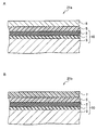
- a and B are sectional views schematically showing another configuration example of the joined body according to the second embodiment of the present invention.
- a and B are side views schematically showing a method for measuring the cohesive failure rate.
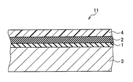
- FIG. 1 is a cross-sectional view schematically showing the configuration of the aluminum alloy plate of the present embodiment.
- a first film 1 made of an oxide film is formed on at least one surface of an aluminum alloy substrate 3, and at least one first film 1 is further formed.
- a second film 2 having a siloxane bond is formed on the part.
- the substrate 3 is made of an aluminum alloy.
- the type of the aluminum alloy forming the substrate 3 is not particularly limited, and various non-heat-treatable or heat-treatable aluminum alloys that are defined in JIS or approximate to JIS depending on the application of the processed member Can be appropriately selected and used.
- the non-heat treatment type aluminum alloy there are pure aluminum (1000 series), Al—Mn series alloy (3000 series), Al—Si series alloy (4000 series), and Al—Mg series alloy (5000 series).
- the heat-treatable aluminum alloy there are an Al—Cu—Mg alloy (2000 series), an Al—Mg—Si alloy (6000 series), and an Al—Zn—Mg alloy (7000 series).
- the substrate 3 preferably has a 0.2% proof stress of 100 MPa or more from the viewpoint of strength.
- Aluminum alloys that can form a substrate that satisfies such characteristics include those containing a relatively large amount of magnesium, such as 2000 series, 5000 series, 6000 series, and 7000 series. These alloys are necessary. It may be tempered accordingly.
- it is preferable to use a 6000 series aluminum alloy because it has excellent age-hardening ability, has a relatively small amount of alloy elements, and is excellent in scrap recyclability and formability.
- Cu copper
- the amount of Cu exposed on the surface of the substrate 3 is less than 0.5 atomic%, so that even when used in a high temperature and humid environment, the adhesive is deteriorated and the substrate 3 is corroded. Can be suppressed.
- the amount of Cu exposed on the surface of the substrate 3 can be measured by high-frequency glow discharge optical emission spectrometry (GD-OES).
- each element except oxygen (O), nitrogen (N), and carbon (C) is specifically formed in the thickness direction of the substrate 3 by high-frequency glow discharge optical emission spectrometry (GD-OES).
- the film 1 is made of an oxide film containing 0.1 atomic percent or more and less than 30 atomic percent of Mg. This coating 1 is provided in order to improve adhesion durability when exposed to a high-temperature and humid environment.
- the aluminum alloy constituting the substrate of the aluminum alloy plate usually contains Mg as an alloy component. When an oxide film that is a composite oxide of aluminum and magnesium is formed on the surface of such a substrate 3, the surface is formed on the surface. Magnesium is present in a concentrated state.
- Mg on the surface becomes a weak boundary layer of the adhesive interface, and the initial adhesiveness is lowered.
- Mg on the surface becomes a weak boundary layer of the adhesive interface, and the initial adhesiveness is lowered.
- it causes hydration of the interface with the adhesive layer and dissolution of the substrate, thereby lowering the adhesion durability of the aluminum alloy plate.
- the amount of Mg in the oxide film is 30 atomic% or more, the adhesion durability of the aluminum alloy plate is lowered.
- the amount of magnesium in the first film 1 made of an oxide film is restricted to less than 30 atomic%.
- adhesion durability can be improved.
- the amount of Mg in the film 1 is preferably less than 20 atomic%, more preferably less than 10 atomic%, from the viewpoint of improving adhesion durability.
- the lower limit of the Mg content of the coating 1 is set to 0.1 atomic% or more from the viewpoint of economy.
- the amount of Mg in the film 1 can be measured by high-frequency glow discharge optical emission spectrometry (GD-OES), similarly to the amount of Cu described above.
- the method for adjusting the amount of Mg in the film 1 is not particularly limited, but examples thereof include acids or mixed acids such as nitric acid, sulfuric acid and hydrofluoric acid, or potassium hydroxide, sodium hydroxide, silicate and carbonate.
- a method of surface treatment with an alkaline solution containing can be applied.
- Mg is dissolved in an acid or alkali solution to adjust the amount of magnesium in the film 1 (oxide film).
- the amount of magnesium in the film 1 can be set in the range described above.
- components other than Mg in the film 1 are oxygen, aluminum, and unavoidable impurities, and the amounts of oxygen and aluminum contained in the film 1 are each preferably 15 to 80 atomic%.
- Inevitable impurities include C, N, Si, Ca, Fe, Cu, Mn, Ti, Zn, and Ni.
- C is less than 10 atomic%
- N is less than 15 atomic%
- other impurities If it is less than 7 atomic%, the inclusion is allowed.
- the film thickness of the film 1 is preferably 1 to 30 nm.
- the ester component in the press oil used when producing a joined body or an automobile member from the rust preventive oil or the aluminum alloy plate 10 used when producing the substrate 3 Adsorption is suppressed.
- coat 1 oxide membrane
- in order to control the film thickness of the film 1 to be less than 1 nm excessive acid cleaning or the like is required, so that productivity is inferior and practicality tends to be lowered.
- excessive pickling causes the Cu contained in the substrate 3 to be concentrated on the surface, and causes a decrease in adhesion durability.
- the film thickness of the film 1 is more preferably 3 nm or more and less than 20 nm from the viewpoints of chemical conversion and productivity.
- the second film 2 has a siloxane bond, and the amount of the film is 0.1 mg / m 2 or more and less than 30 mg / m 2 .
- the MO—Si bond amount between the film 1 and the film 2 can be set within a specific range, and high adhesion durability can be realized.
- the film amount of the film 2 is less than 0.1 mg / m 2 , the influence of Cu exposed on the surface of the substrate 3 and the amount of M—O—Si bond between the film 1 and the film 2 are insufficient. Adhesive durability cannot be obtained.
- the coating amount is 30 mg / m 2 or more, the coating 2 is aggregated and broken by itself, so that the adhesion durability is lowered.
- the coating 2 having a siloxane bond is preferably thin and uniformly formed on the coating 1, but may be applied in an island shape on the coating 1 as long as it is within the range described above.
- MoO-Si bond amount When the film 2 having a siloxane bond is formed on the film 1 made of the oxide film, a MO—Si bond is formed between them.
- M is an element contained in the aluminum alloy substrate 3, specifically, Al and Mg contained in the coating 1.
- This M—O—Si bond is a main bond between the first film 1 made of an oxide film and the second film 2 having a siloxane bond. It is influenced by the structure of the oxide film.
- the amount of M—O—Si bond is analyzed by Fourier transform infrared spectroscopy with parallel polarized light having an incident angle of 75 ° incident on the surface on which the first film 1 and the second film 2 are formed.
- the spectrum obtained in this way can be obtained from the area of the peak derived from the M—O—Si bond generated in the vicinity of 1057 cm ⁇ 1 with 1026 cm ⁇ 1 to 1084 cm ⁇ 1 as the baseline. Note that the position of the peak derived from the M—O—Si bond is shifted in the range of about 1045 to 1065 cm ⁇ 1 depending on the type and ratio of M.
- the peak area generated in the vicinity of 1057 cm ⁇ 1 calculated by the above-described method is 0.01 or more.
- the area of the peak derived from this M—O—Si bond is less than 0.01, the rate of occurrence of interfacial peeling at the interface between the first film 1 and the second film 2 increases, and the desired adhesion durability I can't get sex.
- the peak area derived from the M—O—Si bond is preferably 0.17 or more, and more preferably 0.25 or more.
- additional treatment can be performed in order to increase the MO-Si bond between the first film 1 and the second film 2.
- the oxide film constituting the first film 1 and the group consisting of Si, Zr, Ti, HfV, Nb, Ta, Cr, Mo and W on the surface thereof are selected. It is desirable to contain at least one kind of element. Furthermore, in order not to reduce the MO—Si bond, it is desirable to reduce the amount of carbonate or sulfate present on the surface of the substrate 3.
- FIG. 2 is a flowchart showing a method for manufacturing the aluminum alloy plate 10 of the present embodiment. As shown in FIG. 2, when manufacturing the aluminum alloy plate 10 of this embodiment, substrate production process S1, 1st film formation process S2, and 2nd film formation process S3 are performed. Hereinafter, each step will be described.
- Step S1 Substrate manufacturing process>
- the substrate 3 is manufactured by the following procedure, for example. First, an aluminum alloy having a predetermined composition is melted by continuous casting and cast to produce an ingot (melting casting process). Next, the produced ingot is subjected to homogenization heat treatment (homogenization heat treatment step). Thereafter, the ingot subjected to homogenization heat treatment is hot-rolled to produce a hot-rolled sheet (hot-rolling step).
- the hot-rolled sheet is subjected to rough annealing or intermediate annealing at 300 to 580 ° C., and is subjected to cold rolling at a final cold rolling rate of 5% or more at least once to obtain a cold-rolled sheet (substrate 3) having a predetermined thickness. ) Is obtained (cold rolling process).
- the temperature of rough annealing or intermediate annealing it is preferable to set the temperature of rough annealing or intermediate annealing to 300 ° C. or higher, and thereby the effect of improving formability is more exhibited.
- the temperature of rough annealing or intermediate annealing shall be 580 degrees C or less, and this becomes easy to suppress the fall of the moldability by generation
- the final cold rolling rate is preferably 5% or more, and thereby, the effect of improving the formability is more exhibited.
- the conditions of homogenization heat processing and hot rolling are not specifically limited, It can carry out on the conditions in the case of obtaining a hot rolled sheet normally. Further, intermediate annealing may not be performed.
- Step S2 First film formation step>
- the first film 1 made of an oxide film is formed on the front surface, the back surface, or both of the substrate 3 manufactured in the substrate manufacturing process in step S1.
- the formed oxide film is surface-treated so that the amount of Mg and the amount of M—O—Si bonds are in a specific range.
- the substrate 3 is heated to 400 to 580 ° C. to form an oxide film constituting the first film 1 on the surface of the substrate 3.
- the heat treatment also has an effect of adjusting the strength of the aluminum alloy plate 10.
- the heat treatment performed here is a solution treatment when the substrate 3 is formed of a heat-treatable aluminum alloy, and is annealed (final) when the substrate 3 is formed of a non-heat-treatable aluminum alloy. It is a heat treatment in annealing.
- This heat treatment is preferably rapid heating at a heating rate of 100 ° C./min or more from the viewpoint of improving the strength. Moreover, by setting the heating temperature to 400 ° C. or higher and rapidly heating, the strength of the aluminum alloy plate 10 and the strength after heating (baking) of the aluminum alloy plate 10 can be further increased. On the other hand, by setting the heating temperature to 580 ° C. or less and performing rapid heating, it is possible to suppress a decrease in formability due to the occurrence of burning. Furthermore, from the viewpoint of improving strength, the holding time in the heat treatment is preferably 3 to 30 seconds. Thus, when the substrate 3 is heated at a heating temperature of 400 to 580 ° C., an oxide film having a film thickness of 1 to 30 nm, for example, is formed on the surface of the substrate 3.
- the Mg amount of the first film 1 and the siloxane bond amount formed between the first film 1 and the second film 2 are set to a specific range.
- a mixed acid such as a mixed acid of hydrofluoric acid and sulfuric acid or a mixed acid of hydrofluoric acid and nitric acid, an alkaline solution containing sodium hydroxide, potassium hydroxide, silicate or carbonate, Si, Zr, Ti, Hf, Acids containing V, Nb, Ta, Cr, Mo and W in the form of ions or salts (including mixed acids in which two or more acids are mixed) or alkali solutions (including alkali solutions in which two or more alkalis are mixed) , Alone or in combination, the oxide film formed on the surface of the substrate 3 is treated.
- the oxide film structure control that affects the amount of Mg and the amount of MO-Si bonding in the first film 1 by the treatment with the solution is performed.
- the heat treatment which is a process is also indirectly, since it affects the amount of Mg and the oxide film structure, it is necessary to appropriately adjust the treatment conditions.
- step S1 the adjustment of the amount of Mg in the first film 1 and the adjustment of the film structure for setting the MO—Si bond amount within a specific range are performed once. However, it can also be performed individually by two or more processes.
- Step S3 Second film forming step>
- the second film 2 having a siloxane bond is formed.
- the second film 2 can be formed by using, for example, a silane coupling agent having a reactive functional group such as an amino group, an epoxy group, a methacryl group, a methacryloxy group, a vinyl group, and a mercapto group.
- coat 2 is not limited to what was mentioned above, The silane coupling agent which has various functional groups can be selected suitably, and can be used. .
- the coating amount of the silane coupling agent, coating amount after drying, per side made to be 0.1 mg / m 2 or more 30 mg / m of less than 2.
- the coating amount of the coating 2 is preferably less than 23 mg / m 2 , more preferably less than 15 mg / m 2 .
- the film 2 is preferably thinner because the high adhesion durability obtained when the above-described specific MO—Si bond amount is obtained can be easily secured.
- the coating amount of the coating 2 is less than 0.1 mg / m 2 , it is easily affected by Cu concentrated on the substrate 3 and the amount of M—O—Si bond is insufficient. The cohesive failure rate becomes insufficient.
- the coating amount of the coating 2 described above is, for example, by diluting the silane coupling agent with a solvent (including water as well as an organic solvent) to reduce its solid content concentration and viscosity, or by wet coating with a coater count It can be easily controlled by adjusting the amount.
- the coating method of a silane coupling agent is not specifically limited, The existing method can be applied. Specifically, a coating method by dipping, a method using various coating machines such as a roll coater, a bar coater, a gravure coater, a micro gravure coater, a reverse gravure coater, and a dip coater, a spray coating method, and the like can be applied.
- ⁇ Other processes> In the manufacturing process of the aluminum alloy plate 10 of the present embodiment, other processes may be included between or before and after each process as long as the processes described above are not adversely affected.
- This preliminary aging treatment is preferably performed by heating at 40 to 120 ° C. within 72 hours at a low temperature of 8 to 36 hours.
- pre-aging treatment By performing pre-aging treatment under these conditions, it is possible to improve moldability and strength after baking.
- a foreign matter removing step for removing foreign matter on the surface of the aluminum alloy plate 10 or a defective product removing step for removing defective products generated in each step may be performed.
- the manufactured aluminum alloy plate 10 is coated with press oil on the surface thereof before the fabrication of the joined body or before processing into the member for an automobile.
- the press oil one containing an ester component is mainly used.
- the method and conditions for applying the press oil to the aluminum alloy plate 10 are not particularly limited, and methods and conditions for applying a normal press oil can be widely applied.
- a press containing ethyl oleate as an ester component What is necessary is just to immerse the aluminum alloy plate 10 in oil.
- the ester component is not limited to ethyl oleate, and various materials such as butyl stearate and sorbitan monostearate can be used.
- the aluminum alloy plate 10 of the present embodiment includes a specific amount of bonding between the first film 1 made of an oxide film and the second film 2 having a siloxane bond.
- the interface between the adhesive and the coating 2 having a siloxane bond is chemically bonded, and the coating 1 having the siloxane bond and the coating 1 made of an oxide film is formed. Even between them, there will be chemical bonds.
- the decrease in strength due to hydration is suppressed, so that interfacial peeling can be suppressed, and the decrease in adhesive strength can be suppressed over a long period of time.
- the aluminum alloy plate 10 of this embodiment is provided with the oxide film (coating 1) containing a specific amount of magnesium, the elution of the aluminum alloy substrate 3 can be suppressed, and the alkalinization of the surface of the substrate 3 associated therewith can be suppressed. It can suppress and degradation of adhesive resin can be suppressed. Furthermore, since the aluminum alloy plate 10 of the present embodiment includes a coating (coating 2) having a siloxane bond with a coating amount in a specific range, cohesive failure in the coating 2 is suppressed, and a decrease in adhesive strength is suppressed. Can do.
- the substrate 3 when the substrate 3 is formed of an alloy species having a relatively high Mg content, Mg is concentrated on the surface of the substrate 3 and a weak boundary layer is easily generated at the adhesion interface.
- the substrate 3 since the Mg amount of the first film 1 is controlled within a specific range, the substrate 3 is made of an Al—Mg alloy, an Al—Cu—Mg alloy, Even when formed of an Al—Mg—Si based alloy or an Al—Zn—Mg based alloy, it is possible to suppress interfacial delamination and suppress a decrease in adhesive strength.
- FIG. 3 is a cross-sectional view schematically showing the configuration of the aluminum alloy plate of this modification.
- the same components as those of the aluminum alloy plate 10 shown in FIG. 1 are denoted by the same reference numerals, and detailed description thereof is omitted.
- the aluminum alloy plate 11 of this modification is an adhesive made of an adhesive so as to cover the first film 1 and the second film 2 of the aluminum alloy plate of the first embodiment described above.
- An agent layer 4 is formed.
- the adhesive layer 4 is made of an adhesive, and the aluminum alloy plate 11 of the present modification is joined to another aluminum alloy plate via the adhesive layer 4.
- the adhesive constituting the adhesive layer 4 is not particularly limited, and various adhesives such as a reactive adhesive, a solution adhesive, a water dispersion adhesive, and a solid adhesive typified by a hot melt adhesive. Agents can be used.
- acrylic resin adhesives ⁇ -olefin adhesives, urethane resin adhesives, ethylene-vinyl acetate resin adhesives, epoxy resin adhesives, vinyl chloride resin adhesives, chloroprene rubber adhesives
- Adhesive vinyl acetate resin adhesive, cyanoacrylate adhesive, silicone adhesive, styrene-butadiene rubber adhesive, nitrile rubber adhesive, nitrocellulose adhesive, phenol resin adhesive, silicone adhesive , Polyamide resin adhesive, polyimide adhesive, polyolefin resin adhesive, polyvinyl acetate resin adhesive, polystyrene resin adhesive, polyvinyl alcohol adhesive, polyvinyl pyrrolidone resin adhesive, polyvinyl butyral resin adhesive Agent, polyaromatic adhesive, polymethacrylate resin adhesive Melamine resin adhesives, urea resin adhesives, resorcinol adhesives, and the like. These adhesives are appropriately selected according to the coating 2, the resin, the aluminum alloy, and the manufacturing process in contact with the adhesive layer 4. You can choose
- two or more types of adhesives can be used in combination, functional groups can be added to the adhesive molecules, and silane coupling agents can be added to the adhesive. You can also do it.
- the resin or the precursor thereof may be used as an adhesive.
- the thickness of the adhesive layer 4 is not particularly limited, but is preferably 10 to 500 ⁇ m, and more preferably 50 to 400 ⁇ m.
- the thickness of the adhesive layer 4 is less than 10 ⁇ m, a high adhesion durability is obtained when the aluminum alloy plate 11 and an aluminum alloy plate not provided with another adhesive layer are joined via the adhesive layer 4. Sexuality may not be obtained.
- the thickness of the adhesive layer 4 exceeds 500 ⁇ m, the adhesive strength may be reduced.
- FIG. 4 is a flowchart showing a method for manufacturing the aluminum alloy plate 11 of this modification. As shown in FIG. 4, when the aluminum alloy plate 11 of the present modification is manufactured, an adhesive layer forming step S4 is performed in addition to the steps S1 to S3 described above.
- Step S4 Adhesive Layer Formation Step
- an adhesive layer 4 made of an adhesive is formed so as to cover the first film 1 and the second film 2.
- the method for forming the adhesive layer 4 is not particularly limited. For example, when the adhesive is solid, it is melted (hot melted) by heating, laminated, or the adhesive is removed. A method of spraying or coating a solution dissolved in a solvent on the surfaces of the film 1 and the film 2 can be applied. On the other hand, when the adhesive is in a liquid state, a method of spraying or coating the surfaces of the film 1 and the film 2 as they are can be applied.
- the aluminum alloy plate of the present modification since an adhesive layer is provided in advance, when producing a joined body or a member for an automobile, operations such as applying an adhesive to the surface of the aluminum alloy plate can be omitted. .
- the configuration and effects of the aluminum alloy plate of this modification other than those described above are the same as those in the first embodiment described above.
- the joined body of the present embodiment uses the aluminum alloy plate of the first embodiment described above or its modification.
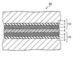
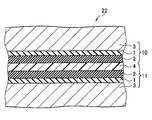
- 5 to 8 are cross-sectional views schematically showing a configuration example of the joined body of this embodiment. 5 to 8, the same components as those of the aluminum alloy plates 10 and 11 shown in FIGS. 1 and 3 are denoted by the same reference numerals, and detailed description thereof is omitted.
- the first coating 1 and the second coating 2 are formed on the two aluminum alloy plates 10 shown in FIG. 1. It can be set as the structure arrange
- the adhesive 5 in the joined body of the present embodiment is not particularly limited, and is a solid adhesive represented by a reactive adhesive, a solution adhesive, a water dispersion adhesive, and a hot melt adhesive.
- Various adhesives such as can be used. Specifically, acrylic resin adhesives, ⁇ -olefin adhesives, urethane resin adhesives, ethylene-vinyl acetate resin adhesives, epoxy resin adhesives, vinyl chloride resin adhesives, chloroprene rubber adhesives Adhesive, vinyl acetate resin adhesive, cyanoacrylate adhesive, silicone adhesive, styrene-butadiene rubber adhesive, nitrile rubber adhesive, nitrocellulose adhesive, phenol resin adhesive, silicone adhesive , Polyamide resin adhesive, polyimide adhesive, polyolefin resin adhesive, polyvinyl acetate resin adhesive, polystyrene resin adhesive, polyvinyl alcohol adhesive, polyvinyl pyrrolidone resin adhesive, polyvinyl butyral resin adhesive Agent, polyaromatic adhesive, polymeth
- the adhesive layer 4 may be used as an adhesive.
- the thickness of the adhesive 5 is not particularly limited, but is preferably 10 to 500 ⁇ m, more preferably 50 to 400 ⁇ m from the viewpoint of improving the adhesive strength.
- both surfaces of the adhesive 5 are the film 1 and the film 2 of the aluminum alloy plate 10 of the first embodiment. Even if it does, the adhesive strength of the interface of the adhesive agent 5 and the membrane
- Examples of the resin molded body 7 include glass fiber reinforced plastic (GFRP), carbon fiber reinforced plastic (CFRP), boron fiber reinforced plastic (BFRP), aramid fiber reinforced plastic (AFRP, KFRP), polyethylene fiber reinforced plastic (A fiber reinforced plastic molded body formed of various fiber reinforced plastics such as DFRP) and Zylon reinforced plastic (ZFRP) can be used. By using these fiber-reinforced plastic molded bodies, it is possible to reduce the weight of the joined body while maintaining a certain strength.
- GFRP glass fiber reinforced plastic
- CFRP carbon fiber reinforced plastic
- BFRP boron fiber reinforced plastic
- AFRP aramid fiber reinforced plastic
- KFRP polyethylene fiber reinforced plastic
- a fiber reinforced plastic molded body formed of various fiber reinforced plastics such as DFRP
- ZFRP Zylon reinforced plastic
- the resin molded body 7 is made of polypropylene (PP), acrylic-butadiene-styrene copolymer (ABS) resin, polyurethane (PU), polyethylene (PE), polyvinyl chloride (PVC). , Nylon 6, nylon 6,6, polystyrene (PS), polyethylene terephthalate (PET), polyamide (PA), polyphenylene sulfide (PPS), polybutylene terephthalate (PBT) and polyphthalamide (PPA) Not engineering plastics can be used.
- the joined bodies 21a and 21b shown in FIGS. 6A and 6B since one surface of the adhesive 5 is joined to the first film 1 or the second film 2 side, similarly to the above-described joined body 20, it is used for automobiles. When used for a member, even if it is exposed to a high temperature and humidity environment, it is not affected by the type of adhesive, and adhesion durability at the interface is improved. Moreover, since the joined body 21b shown to FIG. 6B has joined the aluminum alloy plate 10 and the resin molding 7, it is lightweight compared with the joined body of aluminum alloy plates, By using this joined body 21b, Further weight reduction of the automobile can be realized.
- the other configurations and effects of the joined bodies 21a and 21b shown in FIGS. 6A and 6B are the same as those of the joined body 20 shown in FIG.
- the film 1 and the film 2 of the aluminum alloy plate 10 are bonded to the adhesive layer 4 side of the aluminum alloy plate 11.
- the film 1 or the film 2 of the two aluminum alloy plates 10 and 11 are arranged so as to face each other through the adhesive layer 4 of the aluminum alloy plate 11.
- the first film and the first film are formed on the adhesive layer 4 side of the aluminum alloy plate 11 provided with the adhesive layer 4 shown in FIG. It can also be set as the structure which joined resin moldings 7, such as the other aluminum alloy plate 6 in which the membrane
- the joined bodies 23a and 23b since one surface of the adhesive layer 4 is joined to the film 1 and the film 2 side, when the joined body 23 is used for a member for an automobile as in the above-described joined body 20, it is wet at high temperature. Even if exposed to the environment, the adhesion durability at the interface is improved without being affected by the type of adhesive.
- the joined body 23b shown in FIG. 8B joins the aluminum alloy plate 10 and the resin molded body 7, it is lighter than the joined body of aluminum alloy plates, and an automobile that is required to be lighter. It is suitable for a vehicle member.
- the structures and effects of the joined bodies 23a and 23b shown in FIGS. 8A and 8B other than those described above are the same as those of the joined body 20 shown in FIG.
- a conventionally known joining method can be used as a manufacturing method of the joined bodies 20 to 23, particularly a joining method.
- the method of applying the adhesive 5 to the aluminum alloy plate is not particularly limited.
- an adhesive member prepared in advance with the adhesive 5 may be used, or the adhesive 5 may be bonded to the siloxane bond. You may form by spraying or apply
- the bonded bodies 20 to 23 may be coated with press oil on their surfaces before being processed into automobile members, like the aluminum alloy plates 10 and 11.
- the adhesive agent 5 or the adhesive bond layer 4 is used. Accordingly, it is possible to further join the aluminum alloy plate 6 or the other aluminum alloy plate 6 or the resin molded body 7 on which the coatings 1 and 2 are not formed.
- the joined body of this embodiment is composed of an aluminum alloy plate in which a specific amount of a second film having a siloxane bond is formed on a first film made of an oxide film containing a specific amount of Mg.
- An adhesive or an adhesive layer is bonded to the first film and the second film.
- the joined body of the present embodiment has a coating amount of a coating having a siloxane bond within a specific range, it can suppress cohesive failure in the coating, thereby suppressing a decrease in adhesive strength.
- the manufacturing method of the automobile member of the present embodiment is not particularly limited, but a conventionally known manufacturing method can be applied.
- the joined members 20 to 23 shown in FIGS. 5 to 8 are cut or pressed to produce a predetermined-shaped automobile member.
- the automobile member according to the present embodiment is manufactured from the joined body according to the second embodiment described above, the adhesive or the adhesive layer and the oxide film (first film) even when exposed to a high-temperature and humid environment. Elution of the aluminum alloy substrate can also be suppressed without being substantially affected by the hydration. As a result, in the automotive member of this embodiment, it is possible to suppress interfacial peeling when exposed to a high-temperature and humid environment, and to suppress a decrease in adhesive strength.
- an aluminum alloy plate was produced by the following method and conditions, and its adhesion durability and the like were evaluated.
- the substrate was treated with a nitric acid solution with a solution adjusted to pH 2 or lower at a temperature of 10 to 80 ° C. and a treatment time of 1 to 60 seconds, washed with water within 5 minutes, and dried within 5 minutes after washing with water.
- membrane which is an oxide film was formed.
- a silane coupling agent containing an amino group is diluted with pure water, and the second coating is formed by controlling the coating amount after drying by changing the dilution rate and the count of the bar coater. Examples 1-4 And the aluminum alloy plate of the comparative example 2 was produced. In addition, drying after application
- Examples 5 and 10 Before the nitric acid solution treatment, the substrate is treated with a sodium hydroxide solution adjusted to pH 10 or higher at a temperature of 10 to 80 ° C. and a treatment time of 1 to 60 seconds to change these conditions. As a result, the amount of Mg in the first film, the amount of the second film, the amount of M—O—Si bonds, and the amount of surface Cu were adjusted, and aluminum alloy plates of Examples 5 and 10 were produced. In Examples 5 and 10, the methods other than the above-described sodium hydroxide solution treatment were the same as in Examples 1 to 4.
- Example 6 Comparative Example 3> After the substrate was treated with a sodium hydroxide solution at a temperature of 10 to 80 ° C. and a treatment time of 1 to 60 seconds with a solution adjusted to pH 10 or more, hydrofluoric acid and sulfuric acid were added at 0.01 to 6 mol / L. A hydrofluoric acid / sulfuric acid solution treatment was performed at a temperature of 10 to 80 ° C. and a treatment time of 1 to 60 seconds with a solution adjusted to a pH of 2 or less.
- Example 6 Except for this surface treatment, the same method as in Examples 1 to 4 described above was used, and the surface treatment conditions were changed, so that the amount of Mg in the first film, the film amount of the second film, M ⁇
- the aluminum alloy plates of Example 6 and Comparative Example 3 were prepared by adjusting the O—Si bond amount and the surface Cu amount.
- Example 7 A hydrofluoric acid / sulfuric acid solution with a pH of 10 to 80 ° C. and a processing time of 1 to 60 seconds adjusted to a pH of 2 or less between 0.01 and 6 mol / L of hydrofluoric acid with respect to the substrate After the treatment, a silicate treatment was performed with a sodium silicate solution having a pH of 10 or more at a temperature of 10 to 80 ° C. and a treatment time of 1 to 60 seconds. Except for this surface treatment, the same method as in Examples 1 to 4 was used, and the amount of Mg in the first film, the amount of the second film, the amount of M—O—Si bond, and the amount of surface Cu were determined. An adjusted aluminum alloy plate of Example 7 was produced.
- Example 8> The substrate was subjected to a nitric acid solution treatment with a solution adjusted to pH 2 or lower at a temperature of 10 to 80 ° C. and a treatment time of 1 to 60 seconds, and then with a sodium silicate solution having a pH of 10 or higher at a temperature of 10 to 80 ° C. Silicate treatment was performed with a treatment time of 1 to 60 seconds. Except for this surface treatment, the same method as in Examples 1 to 4 was used, and the amount of Mg in the first film, the amount of the second film, the amount of M—O—Si bond, and the amount of surface Cu were determined. The adjusted aluminum alloy plate of Example 8 was produced.
- Example 9 The examples described above except that the substrate was treated with a nitric acid solution and then treated with a sodium silicate solution of pH 10 or higher at a temperature of 10 to 80 ° C. and a treatment time of 1 to 60 seconds.
- an aluminum alloy plate of Example 9 was prepared in which the amount of Mg in the first film, the amount of film in the second film, the amount of M—O—Si bonds, and the amount of surface Cu were adjusted.
- Comparative Example 1 The aluminum alloy plate of Comparative Example 1 was produced by performing only the acetone cleaning for the substrate without performing the treatment with the various solutions as in the above-described Examples and Comparative Examples.
- the amount of the second film having a siloxane bond was measured by fluorescent X-ray. Specifically, the amount of silicon in the composite film of the first film and the second film was quantified by fluorescent X-ray, and the calculation was performed by converting the intensity of the fluorescent X-ray and the amount of the film using a calibration curve. .
- M-O-Si bond amount The amount of M—O—Si bond was quantified by FT-IR (Fourier transform infrared spectrophotometer: Migna-750 spectrometer manufactured by Nicolet) analysis. Specifically, the FT-IR spectrum measured by the parallel polarization using the incident angle 75 °, when the baseline from 1026cm -1 to 1084cm -1, to M-O-Si bonds generated in the vicinity of 1057cm -1 The area of the derived peak was determined.
- FT-IR Fastier transform infrared spectrophotometer: Migna-750 spectrometer manufactured by Nicolet
- the amount of Mg in the first film which is a composite oxide film of aluminum and magnesium, is determined by oxygen (in the film thickness direction by high-frequency glow discharge optical emission spectrometry (GD-OES: model JY-5000RF manufactured by Horiba Joban Yvon)) in the film thickness direction.
- GD-OES high-frequency glow discharge optical emission spectrometry
- coat (oxide film) was made into the amount of Mg.
- GD-OES model JY-5000RF manufactured by Horiba Joban Yvon
- metal elements such as aluminum (Al), magnesium (Mg), copper (Cu), iron (Fe), and titanium (Ti), silicon (Si), and the like were measured. And the outermost surface amount of copper (Cu) was calculated in percentage.
- 9A and 9B are diagrams schematically showing a method of measuring the cohesive failure rate
- FIG. 9A is a side view
- FIG. 9B is a plan view.
- the adhesive 35 used here is a thermosetting epoxy resin adhesive (bisphenol A type epoxy resin amount 40 to 50%).
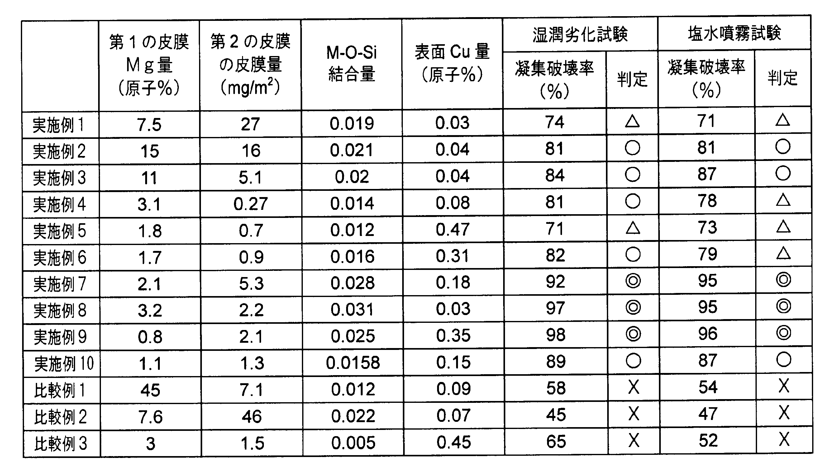
- the wet adhesion test and the salt spray test were performed on the produced adhesion test specimens, and the cohesive failure rate of the adhesive at the adhesion part was evaluated after each test.
- the wet deterioration test was performed by holding the adhesion test specimen in a high temperature and humid environment of 50 ° C. and a relative humidity of 95% for 30 days.
- the salt spray test the temperature in the test tank was set to 35 ° C. using a salt spray tester, and an aqueous sodium chloride solution having a concentration mass of 5% was sprayed onto the adhesion test specimen for 300 hours.
- the adhesion test body after each test was pulled at a rate of 50 mm / min with a tensile tester, and the cohesive failure rate was calculated based on the following formula 1 from the interfacial peel area and adhesion area.
- the test specimen a was used as one side after the tension of the adhesion test specimen, and the test specimen b was used as the other side.
- the cohesive failure rate was the average value of the three samples. Further, the evaluation criteria are that the cohesive failure rate is less than 70% as bad (x), 70% or more and less than 80% as good ( ⁇ ), 80% or more and less than 90% as good ( ⁇ ), and 90% or more as excellent ( ⁇ ), and 70% or more was accepted.
- the aluminum alloy sheets of Examples 1 to 10 had good cohesive failure rate (adhesion durability) because each item was within the scope of the present invention.
- the aluminum alloy plate of Comparative Example 1 had a low cohesive failure rate and poor adhesion durability because the amount of Mg in the first film (oxide film) exceeded the range of the present invention. .
- the aluminum alloy plate of the present invention can be bonded with an adhesive, has a low adhesive strength even under a high temperature and humidity environment, and has excellent adhesion durability. It is.
Landscapes
- Chemical & Material Sciences (AREA)
- Engineering & Computer Science (AREA)
- Materials Engineering (AREA)
- Organic Chemistry (AREA)
- Chemical Kinetics & Catalysis (AREA)
- Electrochemistry (AREA)
- Metallurgy (AREA)
- General Chemical & Material Sciences (AREA)
- Life Sciences & Earth Sciences (AREA)
- Wood Science & Technology (AREA)
- Laminated Bodies (AREA)
Abstract
Description
ここで、前記第1の皮膜中のMg量は、高周波グロー放電発光分光分析法(GD-OES:Glow Discharge-Optical Emission Spectroscopy)により測定した値である。また、前記第2の皮膜の皮膜量は、乾燥後の塗布量である。更に、第1の皮膜と第2の皮膜との間のM-O-Si結合の量は、前述したFT-IRのスペクトルピーク面積を指標にしなければ規定することが難しい。そこで、本発明においては、このM-O-Si結合に由来するスペクトルピークを用いて、第1の皮膜と第2の皮膜との間のM-O-Si結合量を規定している。
前記アルミニウム合金基板は、表面に露出しているCu量を0.5原子%未満とすることができる。なお、ここで規定する「Cu量」は、高周波グロー放電発光分光分析法(GD-OES)により測定した値である。
また、前記アルミニウム合金基板は、例えば、Al-Mg系合金、Al-Cu-Mg系合金、Al-Mg-Si系合金又はAl-Zn-Mg系合金で形成することができる。
本発明に係るアルミニウム合金板は、前記第2の皮膜上に接着剤からなる接着剤層が形成されていてもよい。
本発明の接合体は、例えば、前述したアルミニウム合金板同士が、前記第1の皮膜及び第2の皮膜が形成されている面が対向するように配置され、接着剤を介して接合された構成とすることができる。
又は、前述したアルミニウム合金板の前記第1の皮膜及び第2の皮膜が形成されている面に、接着剤を介して、前記第1の皮膜及び第2の皮膜が形成されていない他のアルミニウム合金板又は樹脂成形体が接合された構成とすることもできる。
又は、前述した接着剤層を備えるアルミニウム合金板と、前述した接着剤層を備えないアルミニウム合金板とが、前記接着剤層が形成されている面と、前記第1の皮膜及び第2の皮膜が形成されている面とが対向するように配置され、前記接着剤層を介して接合された構成にしてもよい。
又は、前述したアルミニウム合金板の前記接着剤層が形成されている面に、前記第1の皮膜及び第2の皮膜が形成されていない他のアルミニウム合金板又は樹脂成形体が接合された構成にすることもできる。
また、前記樹脂成形体としては、例えば繊維強化プラスチック成形体が挙げられる。
先ず、本発明の第1の実施形態に係るアルミニウム合金板について説明する。図1は本実施形態のアルミニウム合金板の構成を模式的に示す断面図である。図1に示すように、本実施形態のアルミニウム合金板10は、アルミニウム合金基板3の少なくとも一方の面に酸化皮膜からなる第1の皮膜1が形成されており、更に第1の皮膜1少なくとも一部にはシロキサン結合を有する第2の皮膜2が形成されている。
基板3は、アルミニウム合金からなる。基板3を形成するアルミニウム合金の種類は、特に限定されるものではなく、加工される部材の用途に応じて、JISに規定される又はJISに近似する種々の非熱処理型若しくは熱処理型のアルミニウム合金から適宜選択して使用することができる。ここで、非熱処理型アルミニウム合金としては、純アルミニウム(1000系)、Al-Mn系合金(3000系)、Al-Si系合金(4000系)及びAl-Mg系合金(5000系)がある。また、熱処理型アルミニウム合金としては、Al-Cu-Mg系合金(2000系)、Al-Mg-Si系合金(6000系)及びAl-Zn-Mg系合金(7000系)がある。
皮膜1は、Mgを0.1原子%以上30原子%未満含有する酸化皮膜からなる。この皮膜1は、高温湿潤環境に曝された場合の接着耐久性の向上を図るために設けられている。アルミニウム合金板の基板を構成するアルミニウム合金には、通常、合金成分としてMgが含まれており、このような基板3の表面にアルミニウムとマグネシウムの複合酸化物である酸化皮膜を形成すると、表面にマグネシウムが濃化した状態で存在することとなる。
第2の皮膜2は、シロキサン結合を有し、皮膜量が0.1mg/m2以上30mg/m2未満である。これにより、皮膜1と皮膜2との間のM-O-Si結合量を特定の範囲にし、高い接着耐久性を実現することができる。一方、皮膜2の皮膜量が0.1mg/m2未満の場合、基板3の表面に露出したCuの影響や皮膜1と皮膜2との間のM-O-Si結合量が不足し、十分な接着耐久性が得られない。
前述した酸化皮膜からなる皮膜1上に、シロキサン結合を有する皮膜2を形成する際に、これらの間にM-O-Si結合が形成される。ここで、「M」は、アルミニウム合金基板3に含まれる元素であり、具体的には、皮膜1中に含有されるAl及びMgなどである。
次に、本実施形態のアルミニウム合金板の製造方法について説明する。図2は本実施形態のアルミニウム合金板10の製造方法を示すフローチャート図である。図2に示すように、本実施形態のアルミニウム合金板10を製造する際は、基板作製工程S1と、第1皮膜形成工程S2と、第2皮膜形成工程S3とを行う。以下、各工程について説明する。
基板作製工程S1では、例えば下記の手順で、基板3を作製する。先ず、所定の組成を有するアルミニウム合金を、連続鋳造により溶解し、鋳造して鋳塊を作製する(溶解鋳造工程)。次に、作製した鋳塊に均質化熱処理を施す(均質化熱処理工程)。その後、均質化熱処理された鋳塊に、熱間圧延を施して熱延板を作製する(熱間圧延工程)。そして、この熱延板に300~580℃で荒焼鈍又は中間焼鈍を行い、最終冷間圧延率5%以上の冷間圧延を少なくとも1回施して、所定の板厚の冷延板(基板3)を得る(冷間圧延工程)。
第1皮膜形成工程では、ステップS1の基板作製工程で作製された基板3の表面若しくは裏面又はその両方に、酸化皮膜からなる第1の皮膜1を形成する。具体的には、基板3を加熱処理して酸化皮膜を形成した後、Mg量やM-O-Si結合量が特定の範囲になるように、形成された酸化皮膜を表面処理する。
ステップS3では、第2皮膜形成工程として、シロキサン結合を有する第2の皮膜2を形成する。この第2の皮膜2は、例えば、アミノ基、エポキシ基、メタクリル基、メタクリロキシ基、ビニル基及びメルカプト基などの反応性官能基をもつシランカップリング剤を使用することにより、形成することができる。なお、第2の皮膜2を形成するシランカップリング剤の官能基は、前述したものに限定されるものではなく、各種官能基を有するシランカップリング剤を、適宜選択して使用することができる。
本実施形態のアルミニウム合金板10の製造工程では、前述した各工程に悪影響を与えない範囲において、各工程の間又は前後に、他の工程を含めてもよい。例えば、第2皮膜形成工程S3後に、予備時効処理を施す予備時効処理工程を設けてもよい。この予備時効処理は、72時間以内に40~120℃で、8~36時間の低温加熱することにより行うことが好ましい。この条件で予備時効処理することにより、成形性及びベーキング後の強度向上を図ることができる。その他に、例えばアルミニウム合金板10の板表面の異物を除去する異物除去工程や、各工程で発生した不良品を除去する不良品除去工程などを行ってもよい。
次に、本発明の第1の実施形態の変形例に係るアルミニウム合金板について説明する。図3は本変形例のアルミニウム合金板の構成を模式的に示す断面図である。なお、図3においては、図1に示すアルミニウム合金板10の構成要素と同じものには同じ符号を付し、その詳細な説明は省略する。図3に示すように、本変形例のアルミニウム合金板11は、前述した第1の実施形態のアルミニウム合金板の第1の皮膜1及び第2の皮膜2を覆うように、接着剤からなる接着剤層4が形成されている。
接着剤層4は、接着剤からなり、本変形例のアルミニウム合金板11は、この接着剤層4を介して他のアルミニウム合金板と接合される。接着剤層4を構成する接着剤は、特に限定されるものではなく、反応系接着剤、溶液系接着剤、水分散系接着剤、ホットメルト接着剤に代表される固形接着剤などの各種接着剤を使用することができる。
次に、本変形例のアルミニウム合金板11の製造方法について説明する。図4は本変形例のアルミニウム合金板11の製造方法を示すフローチャート図である。図4に示すように、本変形例のアルミニウム合金板11を製造する際は、前述したステップS1~S3に加えて、接着剤層形成工程S4を行う。
接着剤層形成工程S4では、第1の皮膜1及び第2の皮膜2を覆うように、接着剤からなる接着剤層4を形成する。接着剤層4の形成方法は、特に限定されるものではないが、例えば、接着剤が固体である場合には、加熱により溶融(ホットメルト)させたり、ラミネートしたり、また、この接着剤を溶剤に溶解させた溶液を皮膜1及び皮膜2の表面に噴霧したり塗布したりする方法を適用することができる。一方、接着剤が液状である場合には、そのまま皮膜1及び皮膜2の表面に噴霧したり塗布する方法を適用することができる。
次に、本発明の第2の実施形態に係る接合体について説明する。本実施形態の接合体は、前述した第1の実施形態又はその変形例のアルミニウム合金板を用いたものである。図5~8は本実施形態の接合体の構成例を模式的に示す断面図である。なお、図5~8においては、図1,3に示すアルミニウム合金板10,11の構成要素と同じものには同じ符号を付し、その詳細な説明は省略する。
本実施形態の接合体は、例えば、図5に示す接合体20のように、図1に示す2枚のアルミニウム合金板10を、第1の皮膜1及び第2の皮膜2が形成されている面同士が対向するように配置し、接着剤5を介して接合した構成とすることができる。即ち、接合体20では、接着剤5は、一面が一方のアルミニウム合金板10の皮膜2側に接合され、その他面が他方のアルミニウム合金板10の皮膜2側に接合されている。
前述した接合体20~23の製造方法、特に接合方法は、従来公知の接合方法を用いることができる。そして、接着剤5をアルミニウム合金板に塗布などする方法は、特に限定されるものではないが、例えば、予め接着剤5によって作製した接着部材を用いてもよいし、接着剤5をシロキサン結合を有する皮膜2の表面に噴霧または塗布することによって形成してもよい。又は、接着剤5が固体である場合には、加熱により溶融(ホットメルト)させたり、ラミネートしたりしてもよい。なお、接合体20~23は、アルミニウム合金板10,11と同様に、自動車用部材への加工前に、その表面にプレス油を塗布してもよい。
次に、本発明の第3の実施形態に係る自動車用部材について説明する。本実施形態の自動車用部内は、前述した第2の実施形態の接合体を用いたものであり、例えば、自動車用パネルなどである。
JIS 6016(Mg:0.54質量%、Si:1.11質量%、Cu:0.14質量%)の6000系アルミニウム合金を用いて、前述した方法により板厚1mmのアルミニウム合金冷延板を作製した。そして、この冷延板を長さ100mm、幅25mmに切断して基板とした。次に、この基板をアルカリ脱脂した後、実体到達温度550℃まで加熱処理し、冷却した。
基板に対して、硝酸溶液処理を行う前に、pH10以上に調整した水酸化ナトリウム溶液を用いて、温度10~80℃、処理時間1~60秒の範囲で処理を行い、これらの条件を変更することで、第1の皮膜中のMg量、第2の皮膜の皮膜量、M-O-Si結合量、表面Cu量を調整し、実施例5,10のアルミニウム合金板を作製した。なお、実施例5,10においては、前述した水酸化ナトリウム溶液処理以外の方法は、実施例1~4と同様にした。
基板に対して、pH10以上に調整した溶液で、温度10~80℃、処理時間1~60秒とした水酸化ナトリウム溶液処理を行った後、弗酸と硫酸を0.01~6mol/Lの間でpH2以下となるように調整した溶液で、温度10~80℃、処理時間1~60秒とした弗酸・硫酸溶液処理を行った。そして、この表面処理以外は、前述した実施例1~4と同様の方法とし、表面処理の条件を変更することで、第1の皮膜中のMg量、第2の皮膜の皮膜量、M-O-Si結合量、表面Cu量を調整して、実施例6及び比較例3のアルミニウム合金板を作製した。
基板に対して、弗酸と硫酸を0.01~6mol/Lの間でpH2以下となるように調整した溶液で、温度10~80℃、処理時間1~60秒とした弗酸・硫酸溶液処理を行った後、pH10以上のケイ酸ナトリウム溶液で、温度10~80℃、処理時間1~60秒としたケイ酸塩処理を行った。そして、この表面処理以外は、前述した実施例1~4と同様の方法とし、第1の皮膜中のMg量、第2の皮膜の皮膜量、M-O-Si結合量、表面Cu量を調整した実施例7のアルミニウム合金板を作製した。
基板に対して、pH2以下に調整した溶液で、温度10~80℃、処理時間1~60秒とした硝酸溶液処理を行った後、pH10以上のケイ酸ナトリウム溶液で、温度10~80℃、処理時間1~60秒としたケイ酸塩処理を行った。そして、この表面処理以外は、前述した実施例1~4と同様の方法とし、第1の皮膜中のMg量、第2の皮膜の皮膜量、M-O-Si結合量、表面Cu量を調整した実施例8のアルミニウム合金板を作製した。
基板に対して、硝酸溶液処理を行った後、pH10以上のケイ酸ナトリウム溶液で、温度10~80℃、処理時間1~60秒としたケイ酸塩処理を行った以外は、前述した実施例5と同様の方法で、第1の皮膜中のMg量、第2の皮膜の皮膜量、M-O-Si結合量、表面Cu量を調整した実施例9のアルミニウム合金板を作製した。
基板に対して、前述した実施例及び比較例のような各種溶液での処理は行わず、アセトン洗浄のみを行って、比較例1のアルミニウム合金板を作製した。
シロキサン結合を有する第2の皮膜の皮膜量は、蛍光X線によって測定した。具体的には、蛍光X線によって第1の皮膜及び第2の皮膜の複合皮膜中のシリコンを定量し、校正曲線を用いて、蛍光X線の強度と皮膜量の換算を行うことにより算出した。
M-O-Si結合量は、FT-IR(フーリエ変換式赤外分光光度計:Nicolet社製 Magna-750 spectrometer)分析により定量した。具体的には、入射角75°の平行偏光使用により測定したFT-IRスペクトルについて、1026cm-1から1084cm-1までをベースラインとしたとき、1057cm-1近傍に生じるM-O-Si結合に由来するピークの面積を求めた。
アルミニウムとマグネシウムの複合酸化膜である第1の皮膜中のMg量は、高周波グロー放電発光分光分析法(GD-OES:ホリバ・ジョバンイボン社製 型式JY-5000RF)により膜厚方向に、酸素(O)、窒素(N)及び炭素(C)を除く各元素、具体的には、アルミニウム(Al)、マグネシウム(Mg)、銅(Cu)、鉄(Fe)及びチタン(Ti)などの金属元素、ケイ素(Si)などを測定した。そして、第1の皮膜(酸化皮膜)中におけるMgの最大ピーク値を、Mg量とした。
高周波グロー放電発光分光分析法(GD-OES:ホリバ・ジョバンイボン社製 型式JY-5000RF)により、膜厚方向に、酸素(O)、窒素(N)及び炭素(C)を除く各元素、具体的には、アルミニウム(Al)、マグネシウム(Mg)、銅(Cu)、鉄(Fe)及びチタン(Ti)などの金属元素、ケイ素(Si)などを測定した。そして、銅(Cu)の最表面量を百分率で算出した。
図9A及び図9Bは凝集破壊率の測定方法を模式的に示す図であり、図9Aは側面図であり、図9Bは平面図である。図9A及び図9Bに示すように、構成が同じ2枚の供試材31a,31b(25mm幅)の端部を、熱硬化型エポキシ樹脂系接着剤によりラップ長13mm(接着面積:25mm×13mm)となるように重ね合わせ貼り付けた。ここで用いた接着剤35は熱硬化型エポキシ樹脂系接着剤(ビスフェノールA型エポキシ樹脂量40~50%)である。

本出願は、2013年5月23日出願の日本特許出願(特願2013-109114)、2014年3月18日出願の日本特許出願(特願2014-055318)に基づくものであり、その内容はここに参照として取り込まれる。
2 第2の皮膜
3 基板
4 接着剤層
5、35 接着剤
6、10、11 アルミニウム合金板
7 樹脂成形体
20、21a、21b、22、23a、23b 接合体
31a、31b 供試材
Claims (11)
- アルミニウム合金基板と、
前記アルミニウム合金基板の少なくとも一方の面に形成され、Mgを0.1原子%以上30原子%未満含有する酸化皮膜からなる第1の皮膜と、
前記第1の皮膜の少なくとも一部に形成され、シロキサン結合を有する第2の皮膜と、を備え、
前記第2の皮膜の皮膜量が0.1mg/m2以上30mg/m2未満であり、
前記第1の皮膜及び第2の皮膜が形成されている面に入射角75°の平行偏光を入射してフーリエ変換式赤外分光法により分析して得たスペクトルにおいて、1026cm-1から1084cm-1までをベースラインとしたとき、1057cm-1近傍に生じるピークの面積が0.01以上である
アルミニウム合金板。 - 前記アルミニウム合金基板は、表面に露出しているCu量が0.5原子%未満である請求項1に記載のアルミニウム合金板。
- 前記アルミニウム合金基板は、Al-Mg系合金、Al-Cu-Mg系合金、Al-Mg-Si系合金又はAl-Zn-Mg系合金からなる請求項1又は2に記載のアルミニウム合金板。
- 前記第2の皮膜上に接着剤からなる接着剤層が形成されている請求項1または2記載のアルミニウム合金板。
- 請求項1~4のいずれか1項に記載のアルミニウム合金板を用いた接合体。
- 請求項1~4のいずれか1項に記載のアルミニウム合金板同士が、前記第1の皮膜及び第2の皮膜が形成されている面が対向するように配置され、接着剤を介して接合されている請求項5に記載の接合体。
- 請求項1~4のいずれか1項に記載のアルミニウム合金板の前記第1の皮膜及び第2の皮膜が形成されている面に、接着剤を介して、前記第1の皮膜及び第2の皮膜が形成されていない他のアルミニウム合金板又は樹脂成形体が接合されている請求項5に記載の接合体。
- 請求項4に記載のアルミニウム合金板と、請求項1~3のいずれか1項に記載のアルミニウム合金板とが、前記接着剤層が形成されている面と、前記第1の皮膜及び第2の皮膜が形成されている面とが対向するように配置され、前記接着剤層を介して接合されている請求項5に記載の接合体。
- 請求項4に記載のアルミニウム合金板の前記接着剤層が形成されている面に、前記第1の皮膜及び第2の皮膜が形成されていない他のアルミニウム合金板又は樹脂成形体が接合されている請求項5に記載の接合体。
- 前記樹脂成形体は繊維強化プラスチック成形体である請求項7又は9に記載の接合体。
- 請求項5~10のいずれか1項に記載の接合体を用いて製造された自動車用部材。
Priority Applications (2)
| Application Number | Priority Date | Filing Date | Title |
|---|---|---|---|
| CN201480028903.9A CN105228822B (zh) | 2013-05-23 | 2014-05-21 | 铝合金板、接合体和汽车用构件 |
| US14/892,123 US10357944B2 (en) | 2013-05-23 | 2014-05-21 | Aluminum alloy sheet, bonded object, and member for motor vehicle |
Applications Claiming Priority (2)
| Application Number | Priority Date | Filing Date | Title |
|---|---|---|---|
| JP2013109114 | 2013-05-23 | ||
| JP2013-109114 | 2013-05-23 |
Publications (1)
| Publication Number | Publication Date |
|---|---|
| WO2014189090A1 true WO2014189090A1 (ja) | 2014-11-27 |
Family
ID=51933642
Family Applications (1)
| Application Number | Title | Priority Date | Filing Date |
|---|---|---|---|
| PCT/JP2014/063512 Ceased WO2014189090A1 (ja) | 2013-05-23 | 2014-05-21 | アルミニウム合金板、接合体及び自動車用部材 |
Country Status (4)
| Country | Link |
|---|---|
| US (1) | US10357944B2 (ja) |
| JP (1) | JP6283240B2 (ja) |
| CN (1) | CN105228822B (ja) |
| WO (1) | WO2014189090A1 (ja) |
Cited By (3)
| Publication number | Priority date | Publication date | Assignee | Title |
|---|---|---|---|---|
| WO2017195802A1 (ja) * | 2016-05-10 | 2017-11-16 | 株式会社神戸製鋼所 | アルミニウム合金材、接着樹脂層付きアルミニウム合金材、アルミニウム合金材の製造方法、及び接着樹脂層付きアルミニウム合金材の製造方法 |
| WO2017195805A1 (ja) * | 2016-05-10 | 2017-11-16 | 株式会社神戸製鋼所 | アルミニウム合金材、接着樹脂層付きアルミニウム合金材、接合体、及びアルミニウム合金材の製造方法 |
| JP2017203186A (ja) * | 2016-05-10 | 2017-11-16 | 株式会社神戸製鋼所 | 金属表面処理用水溶液、金属表面の処理方法、及び接合体 |
Families Citing this family (9)
| Publication number | Priority date | Publication date | Assignee | Title |
|---|---|---|---|---|
| DE102012204636A1 (de) * | 2012-03-22 | 2013-09-26 | Nanogate Ag | Behandlung einer anodisch oxidierten Oberfläche |
| DE102015203128A1 (de) * | 2015-02-20 | 2016-08-25 | Thyssenkrupp Ag | Fahrwerkkomponente, Verfahren zu seiner Herstellung und Verwendung |
| WO2017006805A1 (ja) * | 2015-07-09 | 2017-01-12 | 株式会社神戸製鋼所 | 金属表面処理用水溶液、金属表面の処理方法、及び接合体 |
| JP2017203209A (ja) * | 2015-07-09 | 2017-11-16 | 株式会社神戸製鋼所 | アルミニウム合金材の製造方法、アルミニウム合金材、及び接合体 |
| JP2017203208A (ja) * | 2015-07-09 | 2017-11-16 | 株式会社神戸製鋼所 | 金属表面処理用水溶液、金属表面の処理方法、及び接合体 |
| WO2017006804A1 (ja) * | 2015-07-09 | 2017-01-12 | 株式会社神戸製鋼所 | アルミニウム合金材の製造方法、アルミニウム合金材、及び接合体 |
| WO2017038573A1 (ja) * | 2015-09-02 | 2017-03-09 | 株式会社神戸製鋼所 | アルミニウム合金材、接合体、自動車用部材、アルミニウム合金材の製造方法及び接合体の製造方法 |
| WO2018096952A1 (ja) * | 2016-11-24 | 2018-05-31 | 株式会社神戸製鋼所 | 潤滑皮膜を有するアルミニウム合金板 |
| CN111674120A (zh) * | 2020-05-13 | 2020-09-18 | 宁波华源精特金属制品有限公司 | 一种连接杆 |
Citations (5)
| Publication number | Priority date | Publication date | Assignee | Title |
|---|---|---|---|---|
| JP2003147550A (ja) * | 2001-07-23 | 2003-05-21 | Mitsubishi Alum Co Ltd | 表面処理アルミニウム缶用板材 |
| JP2003342790A (ja) * | 2002-05-27 | 2003-12-03 | Mitsubishi Alum Co Ltd | 表面処理アルミニウム材及び熱可塑性樹脂被覆アルミニウム材 |
| JP2004018906A (ja) * | 2002-06-13 | 2004-01-22 | Mitsubishi Alum Co Ltd | 表面処理アルミニウム材、その製造方法、アルミニウム成形体及びアルミニウム缶 |
| JP2005349691A (ja) * | 2004-06-10 | 2005-12-22 | Mitsubishi Alum Co Ltd | 一般缶用熱可塑性樹脂被覆アルミニウム板 |
| JP2007217750A (ja) * | 2006-02-16 | 2007-08-30 | Furukawa Sky Kk | アルミニウム材及びその製造方法 |
Family Cites Families (9)
| Publication number | Priority date | Publication date | Assignee | Title |
|---|---|---|---|---|
| JP3207588B2 (ja) | 1993-03-05 | 2001-09-10 | 新日本製鐵株式会社 | 接着性に優れるアルミニウム合金板及びその製造方法 |
| JP2000239644A (ja) * | 1999-02-22 | 2000-09-05 | Toray Ind Inc | プライマー組成物 |
| JP2006200007A (ja) | 2005-01-21 | 2006-08-03 | Furukawa Sky Kk | 脱脂後水濡れ性及び接着性に優れた自動車ボディーシート用アルミニウム合金板 |
| US9365931B2 (en) * | 2006-12-01 | 2016-06-14 | Kobe Steel, Ltd. | Aluminum alloy with high seawater corrosion resistance and plate-fin heat exchanger |
| JP2008266663A (ja) * | 2007-04-16 | 2008-11-06 | Furukawa Sky Kk | ラミネート用アルミニウム材及び樹脂被覆アルミニウム材、ならびに、これらの製造方法 |
| CA2721752C (en) * | 2009-11-20 | 2015-01-06 | Korea Institute Of Industrial Technology | Aluminum alloy and manufacturing method thereof |
| CN102312233B (zh) * | 2010-06-29 | 2013-10-30 | 株式会社神户制钢所 | 经表面处理的铝合金板及其制造方法 |
| CN103057198B (zh) * | 2011-10-05 | 2015-07-22 | 株式会社神户制钢所 | 铝合金板、使用该铝合金板的接合体以及汽车用构件 |
| JP2016089261A (ja) * | 2014-11-11 | 2016-05-23 | 株式会社神戸製鋼所 | アルミニウム合金材、接合体、自動車用部材、及びアルミニウム合金材の製造方法 |
-
2014
- 2014-03-18 JP JP2014055318A patent/JP6283240B2/ja not_active Expired - Fee Related
- 2014-05-21 WO PCT/JP2014/063512 patent/WO2014189090A1/ja not_active Ceased
- 2014-05-21 CN CN201480028903.9A patent/CN105228822B/zh not_active Expired - Fee Related
- 2014-05-21 US US14/892,123 patent/US10357944B2/en not_active Expired - Fee Related
Patent Citations (5)
| Publication number | Priority date | Publication date | Assignee | Title |
|---|---|---|---|---|
| JP2003147550A (ja) * | 2001-07-23 | 2003-05-21 | Mitsubishi Alum Co Ltd | 表面処理アルミニウム缶用板材 |
| JP2003342790A (ja) * | 2002-05-27 | 2003-12-03 | Mitsubishi Alum Co Ltd | 表面処理アルミニウム材及び熱可塑性樹脂被覆アルミニウム材 |
| JP2004018906A (ja) * | 2002-06-13 | 2004-01-22 | Mitsubishi Alum Co Ltd | 表面処理アルミニウム材、その製造方法、アルミニウム成形体及びアルミニウム缶 |
| JP2005349691A (ja) * | 2004-06-10 | 2005-12-22 | Mitsubishi Alum Co Ltd | 一般缶用熱可塑性樹脂被覆アルミニウム板 |
| JP2007217750A (ja) * | 2006-02-16 | 2007-08-30 | Furukawa Sky Kk | アルミニウム材及びその製造方法 |
Cited By (6)
| Publication number | Priority date | Publication date | Assignee | Title |
|---|---|---|---|---|
| WO2017195802A1 (ja) * | 2016-05-10 | 2017-11-16 | 株式会社神戸製鋼所 | アルミニウム合金材、接着樹脂層付きアルミニウム合金材、アルミニウム合金材の製造方法、及び接着樹脂層付きアルミニウム合金材の製造方法 |
| WO2017195805A1 (ja) * | 2016-05-10 | 2017-11-16 | 株式会社神戸製鋼所 | アルミニウム合金材、接着樹脂層付きアルミニウム合金材、接合体、及びアルミニウム合金材の製造方法 |
| JP2017203186A (ja) * | 2016-05-10 | 2017-11-16 | 株式会社神戸製鋼所 | 金属表面処理用水溶液、金属表面の処理方法、及び接合体 |
| WO2017195803A1 (ja) * | 2016-05-10 | 2017-11-16 | 株式会社神戸製鋼所 | 金属表面処理用水溶液、金属表面の処理方法、及び接合体 |
| CN109072440A (zh) * | 2016-05-10 | 2018-12-21 | 株式会社神户制钢所 | 金属表面处理用水溶液、金属表面的处理方法和接合体 |
| CN109072440B (zh) * | 2016-05-10 | 2020-10-16 | 株式会社神户制钢所 | 金属表面处理用水溶液、金属表面的处理方法和接合体 |
Also Published As
| Publication number | Publication date |
|---|---|
| CN105228822A (zh) | 2016-01-06 |
| US10357944B2 (en) | 2019-07-23 |
| CN105228822B (zh) | 2017-05-10 |
| JP6283240B2 (ja) | 2018-02-21 |
| JP2015003514A (ja) | 2015-01-08 |
| US20160082702A1 (en) | 2016-03-24 |
Similar Documents
| Publication | Publication Date | Title |
|---|---|---|
| JP6283240B2 (ja) | アルミニウム合金板、接合体及び自動車用部材 | |
| WO2016076344A1 (ja) | アルミニウム合金材、接合体、自動車用部材、及びアルミニウム合金材の製造方法 | |
| WO2015125897A1 (ja) | アルミニウム合金板、接合体及び自動車用部材 | |
| JP6426135B2 (ja) | 酸性溶液および接着剤の塗布を含む、Zn−Al−Mgコーティングを有する金属シートを製造する方法、ならびに対応する金属シートおよびアセンブリ | |
| JP2017203209A (ja) | アルミニウム合金材の製造方法、アルミニウム合金材、及び接合体 | |
| KR20150038677A (ko) | 알루미늄 합금판, 이것을 사용한 접합체 및 자동차용 부재 | |
| KR20210109590A (ko) | 캔 뚜껑 원료를 라미네이트하기 위한 시스템 및 방법 | |
| WO2017006804A1 (ja) | アルミニウム合金材の製造方法、アルミニウム合金材、及び接合体 | |
| JP2017203212A (ja) | アルミニウム合金材、接着樹脂層付きアルミニウム合金材、アルミニウム合金材の製造方法、及び接着樹脂層付きアルミニウム合金材の製造方法 | |
| WO2015151886A1 (ja) | 接着耐久性に優れたアルミニウム合金材および接合体、または自動車部材 | |
| JP6750964B2 (ja) | アルミニウム合金材の製造方法 | |
| WO2017195811A1 (ja) | アルミニウム合金材、接着樹脂層付きアルミニウム合金材、アルミニウム合金材の製造方法、及び接着樹脂層付きアルミニウム合金材の製造方法 | |
| KR101469324B1 (ko) | 자동차용 알루미늄 합금판, 및 이것을 이용한 접합체 및 자동차용 부재 | |
| JP2013159806A (ja) | アルミニウム合金板、これを用いた接合体および自動車用部材 | |
| JP5968956B2 (ja) | アルミニウム合金板、これを用いた接合体および自動車用部材 | |
| JP6721406B2 (ja) | アルミニウム合金材、接着樹脂層付きアルミニウム合金材、アルミニウム合金材の製造方法、及び接着樹脂層付きアルミニウム合金材の製造方法 | |
| JP2017203213A (ja) | アルミニウム合金材、接着樹脂層付きアルミニウム合金材、接合体、及びアルミニウム合金材の製造方法 | |
| JP2017048456A (ja) | アルミニウム合金材、接合体、自動車用部材、アルミニウム合金材の製造方法及び接合体の製造方法 | |
| JP6705694B2 (ja) | アルミニウム合金材、接着樹脂層付きアルミニウム合金材、接合体、及びアルミニウム合金材の製造方法 | |
| WO2017195808A1 (ja) | アルミニウム合金材、接着樹脂層付きアルミニウム合金材、接合体、及びアルミニウム合金材の製造方法 | |
| WO2016031940A1 (ja) | アルミニウム合金材および接合体、ならびに自動車部材 | |
| WO2017038573A1 (ja) | アルミニウム合金材、接合体、自動車用部材、アルミニウム合金材の製造方法及び接合体の製造方法 |
Legal Events
| Date | Code | Title | Description |
|---|---|---|---|
| WWE | Wipo information: entry into national phase |
Ref document number: 201480028903.9 Country of ref document: CN |
|
| 121 | Ep: the epo has been informed by wipo that ep was designated in this application |
Ref document number: 14801112 Country of ref document: EP Kind code of ref document: A1 |
|
| WWE | Wipo information: entry into national phase |
Ref document number: 14892123 Country of ref document: US |
|
| NENP | Non-entry into the national phase |
Ref country code: DE |
|
| 122 | Ep: pct application non-entry in european phase |
Ref document number: 14801112 Country of ref document: EP Kind code of ref document: A1 |